

Page 1
1
Page 2

Table of Contents
About This Guide ------------------------------------------------------------------------------------------------- 4
FCC Compliance Statement ------------------------------------------------------------------------------------ 4
FCC Warning ------------------------------------------------------------------------------------------------------ 4
License Agreement ------------------------------------------------------------------------------------------------ 5
Trademark ---------------------------------------------------------------------------------------------------------- 7
Customer Support ------------------------------------------------------------------------------------------------ 7
Chapter 1. Product Introduction ------------------------------------------------------------------------------- 8
1-1. Product Package Content ----------------------------------------------------------------------- 8
1-2. Product Overview ------------------------------------------------------------------------------- 9
Chapter 2. Hardware Installation ---------------------------------------------------------------------------- 24
2-1. Before You Proceed --------------------------------------------------------------------------- 24
2-2. Hardware Requirement ----------------------------------------------------------------------- 25
2-3. Central Process Unit (CPU) Installation --------------------------------------------------- 26
2-4. Memory Module Installation ---------------------------------------------------------------- 28
2-5. HDD Installation ------------------------------------------------------------------------------ 29
2-6. PTZ Camera Installation --------------------------------------------------------------------- 31
Chapter 3. DVR Operating System -------------------------------------------------------------------------- 34
3-1. DVR System Control Panel Configuration ------------------------------------------------ 35
3-2. DVR Main Program -------------------------------------------------------------------------- 46
3-3. Program Overview ---------------------------------------------------------------------------- 47
Chapter 4. DVR Software Operation ------------------------------------------------------------------------ 58
4-1. Surveillance Server (Witness Pro) ---------------------------------------------------------- 58
4-2. Logging in the Surveillance Server --------------------------------------------------------- 64
4-3. Camera configuration ------------------------------------------------------------------------- 65
4-4. Video playback / Synchronized playback / Text insert playback / ezBack ----------- 82
4-5. Remote Access setup -------------------------------------------------------------------------- 98
4-6. System Configuration /Video display configuration/Connection ezDispatch Server setup/
Save/Load configuration / 2-Way audio setup / Remote Control setup -------------------- 104
4-7. User access setup ----------------------------------------------------------------------------- 112
2
Page 3

Application logs ------------------------------------------------------------------------------ 116
4-8.
4-9. Peripherals setup ------------------------------------------------------------------------------ 118
4-10.
Stop alarm siren ----------------------------------------------------------------------- 122
4-11.
Storage configuration ----------------------------------------------------------------- 122
4-12.
Public address configuration -------------------------------------------------------- 129
4-13.
Control Panel -------------------------------------------------------------------------- 135
Chapter 5. Accessory Programs ----------------------------------------------------------------------------- 140
5-1. ezRServer - Remote Control Server ------------------------------------------------------- 144
5-2. ezSTalk - Two-way voice Communication --------------------------------------------- 147
5-3. ezReboot - Auto-restart the DVR machine ----------------------------------------------- 149
5-4. ezClock - Auto-synchronized time --------------------------------------------------------- 150
5-5. ezHDDSmart - HDD Health Checkup ---------------------------------------------------- 151
5-6. ezUPSCheck ---------------------------------------------------------------------------------- 154
5-7. ezMobileServer – MobileView Server ---------------------------------------------------- 155
5-8. Other Applications --------------------------------------------------------------------------- 156
Chapter 6. Remote Client PC Software ------------------------------------------------------------------- 161
6-1. Start Using FreeView Pro (Remote Client Program) ----------------------------------- 161
6-2. Remote Client Program Operation--------------------------------------------------------- 162
7-1. PDAView & MobileView program installation ------------------------------------------ 190
7-2. PDAView & MobileView Application ---------------------------------------------------- 191
7-3. ezMobileServer Application ---------------------------------------------------------------- 192
3
Page 4

About This Guide
Conventions used in this guide to make sure that you perform certain tasks properly, take note of the following
symbols to use throughout this manual.
WARNING: Information to prevent injury to yourself when trying to complete a task.
CAUTION: Information to prevent damage to the components when trying to complete a task.
IMPORTANT: Information that you must follow to complete a task.
NOTE: Tips and additional information to aid in completing a task.
FCC Compliance Statement
This device complies with part 15 of the FCC Rules. Operation is subject to the following two conditions:
This device may not cause harmful interference, and this device must accept any interference received,
including interference that may cause undesired operation.
FCC Warning
This equipment has been tested and found to comply with the limits for a Class B digital device, pursuant to
Part 15 of the FCC Rules. These limits are designed to provide reasonable protection against harmful
interference in a residential installation. This equipment generates uses and can radiate radio frequency
energy and, if not installed and used in accordance with the instructions, may cause harmful interference to
radio communications. However, there is no guarantee that interference will not occur in a particular
installation. If this equipment does cause harmful interference to radio or television reception, which can be
determined by turning the equipment off and on, the user is encouraged to try to correct the interference by
one or more of the following measures:
Reorient or relocate the receiving antenna.
Increase the separation between the equipment and receiver.
Connect the equipment into an outlet on a circuit different from that to which the receiver is connected.
Consult the dealer or an experienced radio/TV technician for help.
Shielded cables and I/O cords must be used for this equipment to comply with relevant FCC regulations.
4
Page 5

License Agreement
Notice to end-user: please read the following legal agreement carefully. Use of the Witness or any of the
software provided with this agreement constitutes your acceptance of these terms. If you do not agree with
the terms of this agreement, PROMPTLY RETURN the Witness system, Witness, AnyView Pro and
FreeView Pro , any related software and the included items (including the Witness video system, written
materials and containers) to the location where you purchased them for a full refund.
1-1. License Grant. I-View grants to you (either as an individual or an entity) a personal, nonexclusive,
nontransferable license to use one copy of the executable code of the I-View's Witness, FreeView Pro
and AnyView Pro on a single CPU residing on your premises. The term of this Agreement will be for the
duration of I-View’s copyright in the Witness, FreeView Pro and AnyView Pro. You may assign your
rights under this Agreement to a third party who agrees in writing to be bound by this Agreement prior to
the assignment, and provided that you transfer all copies of the Witness, FreeView Pro and AnyView
Pro and related documentation to the third party or destroy any copies not transferred. Except as set forth
above, you may not assign your rights under this Agreement, nor shall you rent, lease, sell, sublicense or
otherwise transfer the Witness, FreeView Pro and AnyView Pro.
1-2. Reverse Engineering. You may not reverse engineer, decompile or otherwise disassemble the Witness,
FreeView Pro and AnyView Pro except to the extent that applicable law expressly prohibits this
restriction.
1-3. Copyright. Title and full ownership rights to the I-View's Witness, FreeView Pro and AnyView Pro will
remain the exclusive property of I-View or its suppliers, and you will not acquire any rights to the
I-View's Witness, FreeView Pro and AnyView Pro except as expressly set forth above.
1-4. Maintenance. I-View is not obligated to provide maintenance or updates to you for the Witness
system and transport to Witness, FreeView Pro and AnyView Pro. However, any maintenance or updates
by I-View shall be covered by the Agreement.
1-5. Disclaimer of Warranty. I-View warrants that the Witness system, the witness FreeView Pro and
AnyView Pro and related software will perform substantially in accordance with the accompanying
documentation and those CD-ROM diskettes are free from any defects for a period of 90 days from the
date of purchase (limited warranty). Except for the foregoing limited warranty, I-View expressly
disclaims any and all other warranties, whether express or implied, including without limitation, the
implied warranties of merchantability, fitness for a particular purpose, and non-infringement of third
5
Page 6

party rights. If law does not permit such disclaimer of any implied warranty, the duration of any such
implied warranties is limited to 90 days from the date of purchase. Some countries do not allow the
disclaimer of implied warranties, limitations on how long an implied warranty lasts, or the exclusion or
limitation of incidental or consequential damages, so such limitation as or exclusions may not apply to
you. This warranty gives you specific legal rights and you may also have other rights, which vary, from
state to state.
1-6. Customer Remedies. In the event the Witness system or related software does not meet or conform to
the Limited Warranty, I-View’s entire liability and your sole and exclusive remedy shall be, at I-View's
option, either to (a) correct the error, (b) help you work around or avoid the error or (c) authorize a refund
so long as the Witness system documentation and CD-ROM diskettes are returned to I-View with a copy
of your receipt. This Limited Warranty is void if failure of the Witness system has resulted from accident,
abuse, or application. Any replacement Witness system will be warranted for the remainder of the
original warranty period.
1-7. No Liability for Consequential Damages. In no event shall its suppliers be liable to you for any
incidental, indirect, special or consequential damages of any kind rising out of or related to this
agreement or use or inability to use the related software, even if I-View has been advised of the
possibility of such damages.
1-8. Please acknowledge that the laws and regulations of the Taiwan R. O. C. restrict the export and
re-export of commodities and technical data of Taiwan R. O. C. origin. You may not download or
otherwise export or re-export the Witness system or related software or any underlying information or
technology except in full compliance with all United States and other applicable laws and regulations.
You agree to indemnify and hold I-View harmless from and against any and all liability arising from or
relating to your breach of this Manual.
1-9. Governing Law; attorneys' fees. The laws of the Taiwan R. O. C will govern this agreement. Without
regard to conflict of law principles. The R. O. C. Convention on Contracts for the International Sale of
Goods is specifically disclaimed. The prevailing party shall be entitled to recover its reasonable attorneys'
fees in the event of a dispute arising out of or relating to this Agreement.
1-10. Entire Agreement. This is the entire agreement between you and I-View with respect to the use of the
Witness, FreeView Pro and AnyView Pro, which supersedes any prior agreement, whether written, or
oral, and all other communications between the parties relating to the subject matter of this Agreement.
6
Page 7

Should you have any questions concerning this Agreement, please contact I-View directly at one of the
numbers or addresses listed at the beginning of this manual.
Trademark
DigiCap II, Deco, e-Witness, @-Witness Pro, u-Witness XP, x-Witness, FreeView Pro, AnyView Pro,
PDAVirw and MobileView are registered trademarks of I-View Communication Inc.
Microsoft, Windows 95, 98, ME, Windows2000, XP, Vista and 7 are registered trademarks of Microsoft
Corporation. All other trademarks are the property of their respective holders.
Customer Support
If technical problems arise with the use of our products in which you and your vendor cannot resolve, please
try the following: If you have an Internet connection, visit the I-View website http://www.i-view.com.tw
(Taiwan) for any software or product updates, or email to support@i-view.com.tw (Taiwan) or Tel:
886-3-510-3001 Fax: 886-3-510-3002 (Taiwan). We are dedicated to providing the highest quality support.
E-mailing our tech support will give you the chance to document each of the above items in a very clear and
concise manner and will give our support team a chance to document any problems and respond with
thoroughly researched answers.
7
Page 8

Chapter 1. Product Introduction
1-1. Product Package Content
Thank you for choosing the I-View Embedded DVR system. Before you start installing the
hardware devices with the DVR, please check the items of the product package with the list
below,
Application program CD and Nero CD
User manual & Power cable
2x SATA disk cable
Remote controller with battery
1 x 16 port Audio cable (For 32 channels Audio recording model)
1 x 16 channel video input cable (For Digi-9600XP/3296Pro Pro)
16 or 32 channels video loop cable (Optional)
16 or 32 channels Spot Monitor video out (Optional)
2 x Ear panel (For 19” Rack mount) and some screws.
USB Mouse & DVI to VGA converter (For second monitor)
If any of the above items is damaged or missing, contact your
retailer.
8
Page 9
1-2. Product Overview
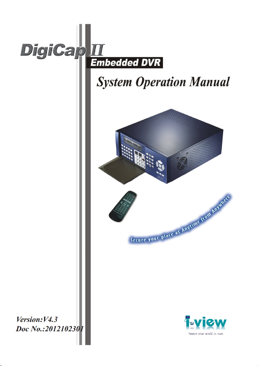
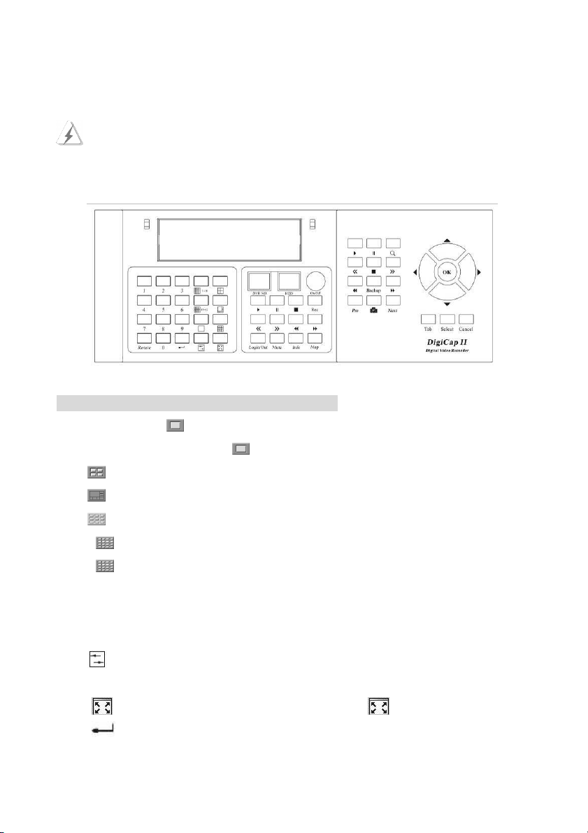
1-2-1. Front Panel of DVR System
The buttons of the front panel provides user to operate the DVR basic functions (e.g.
channel switching functions, display modes functions and playback functions … etc.),
however, user will need a mouse to connect with the DVR for more detail system setting.
Left Section of the DVR Front Panel (Fig 1-3-1.1)
Press “Number (0-9)+ “ to view just one camera’s image on the monitor or TV. For
example: When you select “ 1+6 + “, then you will watch the channel 16 on monitor or TV.
Press key to divide the window into 4 split screens.
Press key to divide the window into 8 split screens.
Press key to divide the window into 9 split screens.
Press “ 1-16 ” key to divide the window into 16 split screens. (Camera 1 - 16)
Press “ 17-32 ” key to divide the window into 16 split screens. (Camera 17 - 32) (For
Digi-3200Pro only)
Press “ Rotate “ key to rotate cameras views on screen automatically. Press “ 0 “ + “ Rotate
“ the rotation will be stopped. The detail settings please refer to Chapter 6-3.
Press key to toggle between non real-time viewing (Recording mode) and real-time viewing
(Live view mode) of video displays. The
detail settings please refer to Chapter 6-3.
Press key will hide the tool bar of main screen until key is pressed again.
Press key that function same as enter or OK.
9
Page 10
Middle Section of the DVR Front Panel (Fig 1-3-1.1 & Fig 1-3-1.2)
DVR NO.: Display for the ID address of DVR. The detail setting please refers to
Chapter 5-3.
HDD: Indicate the status of HDD.
Press “On/Off “ key to Turn on / off DVR.
Press “ Rec “ key to start recording the video. Press “ 0 “ + “ Rec “ the stop recording.
The detail settings please refer to Chapter 6-3.
Press “Map” to show the information and map of DVR. Press “ 0 “ + “ Map “ to
close the Map screen. The detail settings please refer to Chapter 7
Press “Login/Out” to login/logout of DigiCap II DVR. Press “ Cancel “ to close the
function.
Press “Mute” to stop the sound alarm when camera is triggered.
Press ► key to play back all videos.
Press key once to pause all videos.
Press ■ key to stop playback all videos.
Press << key to jump to previous frame of all videos.
Press >> key to jump to next frame of all videos.
Press ◄◄ key to decreases the playback frame rate of all videos.
Press ►► key to increases the playback frame rate of all videos.
Press “ Info “ to list the information of all video clips, and you can quickly search and
assign a video clip to playback. Press “ 0 “ + “ Info “ to close this function.
Fig 1-2-1.1 Fig 1-2-1.2
10
Page 11
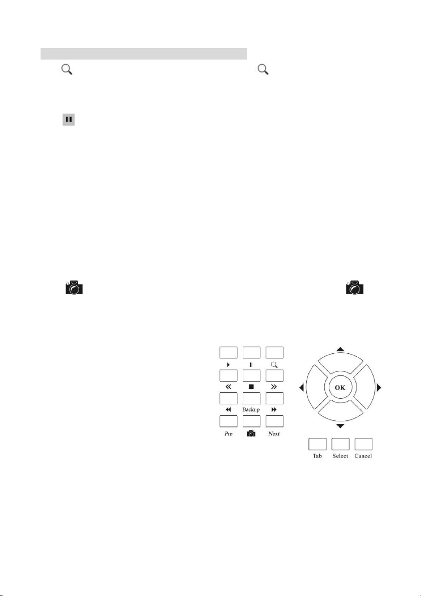
Right Section of the DVR Front Panel (Fig 1-3-1.3)
Press key to search for videos in database. Press “ 0 “ + “ “ to close the playback
function.
Press ► key to play back the video files which you select.
Press key once to pause the video file which you select.
Press ■ key to stop playback the video file which you select.
Press << key to jump to previous frame of the video file, which you select.
Press >> key to jump to next frame of videos file which you select.
Press ◄◄ key to decreases the playback frame rate of video file, which you select.
Press ►► key to increases the playback frame rate of video file, which you select.
Press “ Pre ” key to jumps to the previous video, which you select.
Press “ Next ” key to jumps to the next video, which you select.
Press “ Back up “ key will copy current video clip to a specific location for archiving. Press “ 0
“ + “Back up “ to close the backup video file function.
Press “ “ key to capture the video screen as a BMP or JPEG format. Press “ 0 “ + “ “ to
close the backup picture file function.
Press ▲(Up ), ►(Right), ▼(Down) and ◄(Left) key to select the item.
Press ” OK “ key to enter the selection item.
Press ” Tab“ key to change the section.
Press ” Select “ key to enter the selection item.
Press ” Cancel “ key to quick the selection item.
Fig 1-2-1.3
11
Page 12
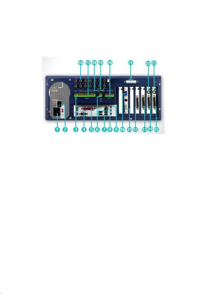
1-2-2. Back Panel of DVR System
According to the different model of the DigiCap DVR, their back panel configuration
may be different, please read carefully the introduction below.
Digi-9600XP /Digi-9600XP-A Back Panel description:
1. Power plug: Plug power cable.
2. Power switch: Turn on/off power supply.
3. RS-485 Port: The communication port to control the Speed Dome and P/T/Z
camera.
4. Series port: Connect to RS-232 device such as Modem..
5. Printer port: Connect to the printer.
6. Panic button port: Connect to push button for emergency call. (Dry contact
input only).
7. USB port: Connect to USB device, such as USB external storage device.
8. LAN port: For TCP/IP connection.
9. Audio plug: Including Microphone in / Speaker out /Line in.
10. VGA port: The first Monitor VGA port.
11. DVI port: The second monitor connection port.
12. Video input: The 16 (17-32) video input.
13. Audio input: 17-32 audio input. (For Digi-9600XP-A only).
12
Page 13
14. Video loop output: The optional 16 (1-16) cameras video loop output.
15. Video loop output: The optional 16 (17-32) cameras video loop output.
16. Video input: The 16 (1-16) video input.
17. Sensor input: 16 sensors input. (For Dry contact input only).
18. Main Monitor 0 output: Display 1-16 spilt video on TV.
19. Main Monitor 1 output: Display 17-32 spilt video on TV.
20.. Relay output: 3 relay output.
21. Audio input: 1-16 audio input. (For Digi-9600XP-A only).
22. Spot Monitor 0 output: The optional 16 (1-16) cameras spot monitor 0 output.
23. Spot Monitor 1 output: The optional 16 (17-32) cameras spot monitor 0 output.
The video looping video cannot be used when add the Spot monitor video out.
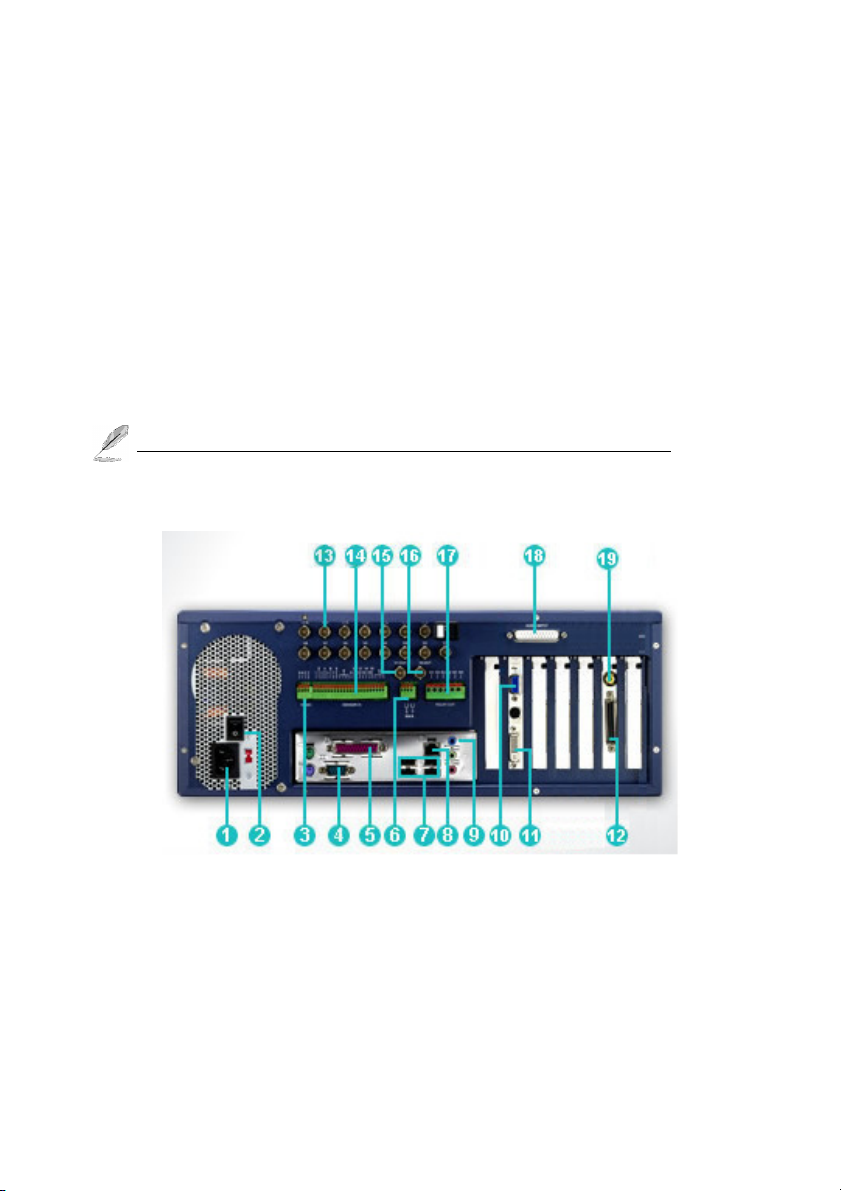
Digi-4800XP /Digi-4800XP-A Back Panel description:
1. Power plug: Plug power cable.
2. Power switch: Turn on/off power supply.
3. RS-485 Port: The communication port to control the Speed Dome and P/T/Z camera.
4. Series port: Connect to RS-232 device such as Modem.
5. Printer port: Connect to the printer.
6. Panic button port: Connect to push button for emergency call. (Dry contact input only)
13
Page 14
7. USB port: Connect to USB device, such as USB external storage device.
8. LAN port: For TCP/IP connection.
9. Audio plug: Including Microphone in / Speaker out /Line in..
10. VGA port: The first Monitor VGA port.
11. DVI port: The second monitor connection port.
12. Video loop output: The optional 16 (1-16) cameras video loop output.
13. Video input: The 16 (1-16) video input.
14. Sensor input: 16 sensors input. (For Dry contact input only).
15. Main Monitor 0 output: Display 1-16 spilt video on TV.
16. Revise:
17.. Relay output: 3 relay output.
18. Audio input: 1-16 audio input. (For Digi-4800XP-A only)
19. Spot Monitor 0 output: The optional 16 (1-16) cameras spot monitor 0 output.
The video looping video cannot be used when add the Spot monitor video out.
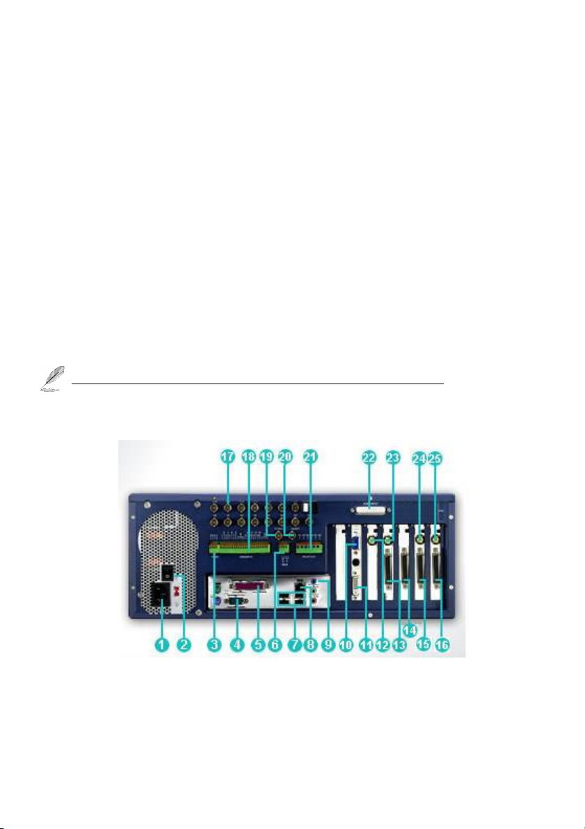
Digi-3296Pro/3296Pro-A Back Panel Description:
1. Power plug: Plug power cable.
2. Power switch: Turn on/off power supply.
3. RS-485 Port: The communication port to control the Speed Dome and P/T/Z camera.
14
Page 15

4. Series port: Connect to RS-232 device such as Modem.
5. Printer port: Connect to the printer.
6. Panic button port: Connect to push button for emergency call. (Dry contact input only)
7. USB port: Connect to USB device, such as USB external storage device.
8. LAN port: For TCP/IP connection.
9. Audio plug: Including Microphone in / Speaker out /Line in..
10. VGA port: The first Monitor VGA port.
11. DVI port: The second monitor connection port.
12. Single video output: The1-16 single video output.
13. Video input: The 16 (17-32) video input.
14. Audio input: 17-32 audio input. (For Digi-3296Pro-Aonly)
15. Video loop output: The optional 16 (1-16) cameras video loop output.
16. Video loop output: The optional 16 (17-32) cameras video loop output.
17. Video input: The 16 (1-16) video input.
18. Sensor input: 16 sensors input. (For Dry contact input only).
19. Main Monitor 0 output: Display 1-16 spilt video on TV.
20. Main Monitor 1 output: Display 17-32 spilt video on TV.
21.. Relay output: 3 relay output.
22. Audio input: 1-16 audio input. (For Digi-3296Pro-Aonly)
23. Video out: Display 17-32 single video on TV.
24. Spot Monitor 0 output: The optional 16 (1-16) cameras spot monitor 0 output.
25. Spot Monitor 1 output: The optional 16 (17-32) cameras spot monitor 0 output..
The video looping video cannot be used when add the Spot monitor video out.
15
Page 16

Digi-3248Pro/3248Pro-A Back Panel Description:
1. Power plug: Plug power cable.
2. Power switch: Turn on/off power supply.
3. RS-485 Port: The communication port to control the Speed Dome and P/T/Z camera.
4. Series port: Connect to RS-232 device such as Modem.
5. Printer port: Connect to the printer.
6. Panic button port: Connect to push button for emergency call. (Dry contact input only)
7. USB port: Connect to USB device, such as USB external storage device.
8. LAN port: For TCP/IP connection.
9. Audio plug: Including Microphone in / Speaker out /Line in..
10. VGA port: The first Monitor VGA port.
11. DVI port: The second monitor connection port.
12. Single video output: The1-16 single video output.
13. Video input: The 16 (17-32) video input.
14. Video loop output: The optional 16 (1-16) cameras video loop output.
15. Video loop output: The optional 16 (17-32) cameras video loop output.
16. Video input: The 16 (1-16) video input.
17. Sensor input: 16 sensors input. (For Dry contact input only).
18. Main Monitor 0 output: Display 1-16 spilt video on TV.
16
Page 17

19. Main Monitor 1 output: Display 17-32 spilt video on TV.
20.. Relay output: 3 relay output.
21. Audio input: 1-16 audio input. (For Digi-3248Pro-Aonly)
22. Video out: Display 17-32 single video on TV.
23. Spot Monitor 0 output: The optional 16 (1-16) cameras spot monitor 0 output.
24. Spot Monitor 1 output: The optional 16 (17-32) cameras spot monitor 0 output.
The video looping video cannot be used when add the Spot monitor video out.
Digi-1648 Pro Back Panel Description:
1. Power plug: Plug power cable.
2. Power switch: Turn on/off power supply.
3. RS-485 Port: The communication port to control the Speed Dome and P/T/Z camera.
4. Printer port: Connect to the printer.
5. Series port: Connect to RS-232 device such as Modem.
6. Panic button port: Connect to push button for emergency call. (Dry contact input )
7. USB port: Connect to USB device, such as USB external storage device.
8. LAN port: For TCP/IP connection.
9. Audio plug: Including Mic in / Speaker out /Line in.
10. VGA port: The first Monitor VGA port.
11. DVI port: The second monitor connection port.
17
Page 18

12. Video loop output: The optional 16 (1-16) cameras video loop
13. Video in: 1-16 cameras video input.
14. Sensor input: 16 sensors input. (For Dry contact input only)
15. Main Spot Monitor 0 output: Display 1-16 split video on TV.
16. Video out: Display 1-16 single video output.
17. Relay output: 3 relay output.
18. Audio input: 1-16 audio input. (For Digi-1648 Pro-A only)
19. Spot Monitor 0 output: The optional 16 (1-16) Spot Monitor 0 output. (Option)
The video looping video cannot be used when add the Spot monitor video out.
18
Page 19

1-2-3. DVR Remote Controller Functions
48 keys Remote controller
The buttons functions of the remote controller are for user to operate the DVR basic
functions (e.g. channel switching functions, display modes functions and playback
functions … etc.), however, user will need a mouse to connect with the DVR for detail
system setting.
Playback single video file
If you want to playback the single video clip, press “ S Play “ key and then select the function key
of playback.
Playback multi videos file
If you want to playback the single video clip, press “ M Play “ key and then select the function key
of playback. (Default is M Play mode) The he functions in Remote controller behave similarly of
chapter 5-2 Middle Near Panel.
Display single video out on TV
If you want to control the Single video out on TV, press “Number key+ S Play “ displays the single
video on TV. For example: When you select “ 1+6 + S Play “, then you will watch the channel
16 on monitor or TV. Press “0 + S Play “ to rotate all camera on TV.
Display split-screen video out on TV
Press the “ Number key + function key “or “ , , , 1-16 or 17-32 ” key
directly to show single or split-screen video on TV
.
19
Page 20

27 keys Remote controller (Optional)
This remote controller special design for the spot monitor application. On your remote controller,
there should be buttons labeled with function button and numbers representing the main
monitor/spot Monitor and camera numbers. Points the remote controller at the sensor/receiver,
press the number of the camera you wish you to on the TV and it would appear.
Number key: For the video channels selections. Simply press the number key from the
“Display” section to display the selected video channel on the connected monitor.
Return (Single video out): To return back to the channels scrolling display mode while in the
signal video display mode.
F1: Press F1 button to assign the video out of Main Monitor 0 to show on the TV.
F2: The Press F2 button to assign the Single TV out (1-16) of DVR to show on the TV.
F3: Press F3 button to assign the video out of Main Monitor 1 to show on the TV.
F4: Press F4 button to assign the Single TV out (17-32) of DVR to show on the TV.
Split Section: Push the splitter key on “ Split ” section, and then you will watch the splitter
video on TV. (Click the ● icon to change 6, 10, 13 split screen sequence).
Return: After you use Display function, then you will return to all channels scroll.
Enter: Press the Enter button to display OSD Menu on the TV.
1
.
When you press the Enter, then F1 button that the control will become to “ 2 MUX + Single
TV Out “Mode. You can control the Single TV and split video output separately, the “ Main
monitor 0 & Spot Monitor 0 “ and “ Main monitor 1 & Spot Monitor 1 “ will synchronize the
video display. The control button as below:
Press F1 button to control the main monitor 0 and spot Monitor 0 display.
Press F2 button to control the Single TV Out (1-16).
20
Page 21

Press F3 button to control the main monitor 1 and spot Monitor 1 display.
Press F4 button to control the Single TV Out (17-32)
2. When you press the Enter, then F2 button that the control will become to “ 4 MUX “ mode.
You can control Main monitor 0, Main monitor 1, Spot Monitor 0 and Spot Monitor 1
separately. The control button as below:
Press F1 button to control the main monitor 0 display.
Press F2 button to control the spot monitor 0 display.
Press F3 button to control the main monitor 1 display.
Press F4 button to control the spot monitor 1 display.
For example:
1. If you want to view the camera 22 of single TV out on TV; click “ Enter “ button, then
Press “ F4 “ button and then entry “ 6 “ number key, you will watch the camera 22 single
video on TV.
2. If you want to view the 4 split video (Camera 1-4) of Spot Monitor 1 on TV; click
“ Enter “ button, then Press “ F1 “ button and then entry “ 4 split way“ button, you will
watch the camera 4 split video on TV.
Sensor cable
To install the sensor, simply plug the end of the sensor device (“1” connector) into the Sensor
connector of inside of DVR. There is a phone jack on each board of DVR, this port for the
sensor input. All the signal of sensor link together, so plug a sensor that can control all main
monitor and spot monitor display at a time if all TVs at a same place.
1. Please shut down the power of DVR when you plug in the sensor cable into the board,
otherwise it will cause the sensor damage.
2. Make sure that the sensor itself is not covered and is facing the place from where you
will be using the remote controller.
3. Do not use 27 Keys remote controller on the DVR site, because the DVR
will be reset when press “ F4 “ button of 27 Keys remote controller.
4. Make sure that the sensor itself plug into the phone jack completely.
21
Page 22

5. The system allows to extent sensor cable for control the TV out from far away site via
Switch
↓ ↑ ↓ ↑ ↓ ↑ ↓ ↑ ↓ ↑ ↓ ↑ ↓ ↑ ↓
↓ ↓ ↑ ↑ ↓ ↓ ↑ ↑ ↓ ↓ ↑ ↑ ↓ ↓ ↑
↓ ↓ ↓ ↓ ↑ ↑ ↑ ↑ ↓ ↓ ↓ ↓ ↑ ↑ ↑
↓ ↓ ↓ ↓ ↓ ↓ ↓ ↓ ↑ ↑ ↑ ↑ ↑ ↑ ↑
Remote Controller. Please follow the process as below to achieve this function:
a. Please use the shading cable such as 28#2C+S type.
b. The sensor cable includes 3-wire cable: Red (DC 5V), Shading cable (Ground),
White (Signal).
c. Using Standard Cat. 6 STP cable can extension sensor signal and power up to 300
meters, this test result just for reference only and you still need to do the
environment testing for the application.
Control multi DVRs via single Remote controller
Sometime there are several DVR in one place. Please follow the below steps to control
multi DVR via single Remote controller:
1. There is a Dip switch on the inside of front panel for the setting ID address of DVR,
the setting description as below:
↑
: Disable ↓: Enable, S5-S8: No function
S1-S4: For ID address setting; the table of ID address as below
0 1 2 3 4 5 6 7 8 9 10 11 12 13 14 15
ID
S1
S2
S3
S4
2. It will show the ID address on the LED of front panel after your setting Dipswitch.
3. Press “ ID “ key and then select the “Number “ of DVR, which you want to control. The
↑
↑
↑
↑
The default ID address is “ 0 ”. It does not need to change the setting when use a DVR
only. Control the DVR via Remote controller directly.
The keypad of front panel will be no function when the LED is flashing.
22
Page 23

number LED of front panel will be flashed. You can start to use the Remote controller when the
LED is flashing.
4. Press “ Return “ key to
stop the function of Remote controller.
23
Page 24

Chapter 2. Hardware Installation
After user finish the CPU, RAM and HDD installation, please remember to go to the system Control
Panel to configure the DVR system for installed hardware devices operating properly. For detail about
the setup DVR system configuration in control panel, please refer to chapter 3-1 DVR systems
Control Panel Configuration.
2-1. Before You Proceed
Take note of the following precaution before you install the components (CPU, HDD and RAM).
1. Unplug the power cord from the wall socket before touching any component.
2. Use a grounded wrist strap or touch a safety grounded object or to metal object, such as
the power supply case. Before handing components to avoid damaging them due to
static electricity.
3. Hold components by the edges to avoid touching the ICs on them.
4. Whenever you uninstall any components, place it on a grounded antistatic pad or in the
bag that came with the component..
5. Before you install or remove any component, ensure that the power supply is switched off
or the power cord is detached from the power supply. Failure to do so may cause severe
damage to DVR, peripherals, and/or components.
24
Page 25

2-2. Hardware Requirement
CPU & RAM request, please refer to the table 2-2.1.
7200RMP hard drive speed or better recommended.
Recommend to use the 32M Bytes or better buffer.
Please use 7200 RMP HDD when you user 32 channels or Digi4800/9600 XP DVR.
Speakers are required for sound alarm/effects.
Microphone with 2Vp-p output required for audio recording.
Table 2-2.1.
Item
Model
Digi-4800 XP
CPU RAM Recording rate
400/480 fps Full
Q8200 or better
2 GB
D1
Digi-9600 XP
Q8200 or better
2 GB
800/960 fps Full
D1
400/480 fps CIF
Digi-1648 Pro
E2200 or better 2 GB
Digi-3248 Pro
Duo E5300 or
2 GB
better
400/480 fps CIF
400/480 fps CIF
Digi-3296 Pro
Q8200 or better 2 GB
25
Page 26

2-3. Central Process Unit (CPU) Installation
2-3-1. CPU Installations: Power Management Setup
The DVR’s board comes with a surface mount Socket 775 (LGA775) design for Intel Pentium 4
Processor in the 755-land package.
Fig.2-3-1.3
Fig.2-3-1.1
Fig.2-3-1.4
Fig.2-3-1.2
Fig.2-3-1.5
Fig. 2-3-1.6
Follow the steps below for CPU installation
1.) Locate the CPU socket on the platform. (Fig. 2-3.1).
2.) Press the load lever with your thumb (A) and remove it to the left (B) until it is released from the
retention tab. (Fig. 2-3.2)
3.) Lift the load lever in the direction of arrow to a 135-degree angle. (Fig. 2-3.3).
4.) Lift the load plate with your thumb and forefinger to a 100-degree angle (A), and then push the
PnP cap from the load plate window to remove (B). (Fig. 2-3.4).
5.) Position the CPU over the socket, making sure that the gold triangle is on the bottom-left corner
of the socket. The socket alignment key should fit into the CPU notch. (Fig. 2-3.5).
26
Page 27

6.) Close the load plate (A), then push the load lever (B) until it snaps into the retention tab. (Fig.
on the top of the installed CPU, making sure that the four fasteners match
2-3.6) The CPU fits in only correct orientation.
1. Unplug the power cord from the wall socket before touching any component.
2. DO NOT force the CPU into the socket to prevent bending the connectors on the
socket and damage the CPU!
Fig. 2-3.7
Fig. 2-3.8
2-3-2. The heat sink and fan installation
1.) Place the heat sink
the hole of platform.
2.) Push down two fasteners at a time in a diagonal sequence to secure the heat sink and fan
assembly in place.
27
Page 28

2-4. Memory Module Installation
The Platform comes with Double Data Rate II (DDR II ) socket. These sockets support up to 4 GB
system memory.
For optimum capability, it is recommended that you obtain memory modules from the same
vendor.
The following figure shows the location of DDR II sockets and steps to install a RAM.
1. Unlock a socket by pressing the retaining clips outward.
2. Align a DIMM on the socket such that the notch on the DIMM matches the break on the socket.
3. Firmly insert the DIMM into socket until the retaining clips snap back in place and the DIMM is
properly seated.
Make sure to unplug the power supply before adding or moving DIMMs or other system
components. Failure to do so may cause severe damage to both the platform and the
components.
28
Page 29

2-5. HDD Installation
The Platform of Digi-1648Pro/3248Pro/3296Pro comes with 1 IDE sockets (1st and 2nd IDE) and 7
(5+2; 2 HDDs for backup) pcs x SATA II sockets. The DigiCap II series DVR support up to 6 pcs x
SATA II HDD.
The default setting of the manufacture for the 1st IDE socket is used of the DVD+-RW and
flash memory.
Please follow the steps below to install the Series ATA/SATA II Hard disk.
Step 1. Remove the case cover of the DigiCap II Series DVR.
Step 2. Use the SATA/SATA II cable(s) to connect with the hard drive(s) (SATA II HDD) and
the motherboard connectors(s) (SATA cable for the SATA II slot) as showing in Fig.
2-6.1.
Fig. 2-6.1 SATA socket
If user tries to install the SATA/SATA II hard drive(s) for DigiCap II image storage, please
use SATA cable(s) to connect with the SATA/SATA II/III hard drive(s) and the
motherboard SATA slots for optimum data transmission performance.
Step 3. Connect the inner power cables with each hard drives as showing in Fig.2-6.2.
29
Page 30

Step 4. Mount the connected hard drives into the DigiCap II inner chassis 1 and chassis 2 as
showing in Fig 2-6.3 (Allows to install 6 HDD up to 18TB by optional extra RAID
interface).
Step 5. Screw backs the DigiCap II case cover to complete the HDDs installation.
Fig. 2-6.2
Fig 2-6.3 Chassis 1 and 2 for hard drive(s) installation
30
Page 31

2-6. PTZ Camera Installation
Speed dome camera Installation
P/T Motor Installation
:
:
The last NC-180AZ PTZ Receiver must be terminated.
31
Page 32

Speed dome controlling port description:
Pin assignment:
RS-485 & Relay out
R1: Relay #1 out R2: Relay #2 out R3: Relay #3 out
Y: Transmitter (TX +) Z: Transmitter (TX-) A: Receiver (RX+) B: Receiver (RX-)
Relays output: Connect one voltage line and ground of Controller (Such as light) to
the desired “Relay output” number of Control Board.
RS-485: Connect to NC-180AZ PTZ Receiver or Speed dome camera.
Dip switch of Control Board:
The dip switch for the bound rate setting, please refer to the table as below:
Baud rate
Pin
Pin 1 & Pin 2 Short Open Short Open
Pin 3 & Pin 4 Short Short Open Open
1200 2400 4800 9600
Digital input Module:
G1 – G3: Common 1: Sensor #1 in 2: Sensor #2 in 3: Sensor #3 in
4: Sensor #4 in 5: Sensor #5 in 6: Sensor #6in 7: Sensor #7 in
8: Sensor #8 in 9: Sensor #9 in 10: Sensor #10 in 11: Sensor #11 in
12: Sensor #12 in 13: Sensor #13 in 14: Sensor #14 in 15:Sensor #15 in
16: Sensor #16 in
Sensors in: Each sensor-in port can receive trigger signals from other device to
trigger video recording, alarm and notify function. Please use the dry contact for
the sensor in; otherwise it will cause the damage of sensor input.
32
Page 33

1. The “Sensor In” port for Dry contact input only, otherwise it will cause the device
damage.
2. The “Relay Out” port for NO (Normal Open) type device only.
3. The current must be less than 10A, when controlling electric device to relay output.
33
Page 34

Chapter 3. DVR Operating System
DVR System Main Screen
Take note of the following precaution before you start to configure the DVR system.
1. The DigiCap II provides Bar-bond system for the distributor, therefore it dose NOT include the
HDD and License of Embedded XP. So you must install the HDD first by yourself. Especially
you MUST buy the license of Embedded XP from Microsoft, otherwise using the O.S. will
be ILLEGALITY.
2. You MUST obey the rules of Microsoft to process the license of Embedded. XP.
3. To avoid the virus problem, please remove the LAN cable and reboot DVR system when you
start to setup the DVR system configuration.
34
Page 35

3-1. DVR System Control Panel Configuration
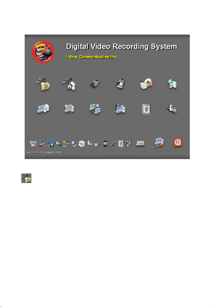
Once user has finished the CPU, RAM and HDD installation, please click the Control
Panel icon ( ) from the right side bottom corner of the DVR system main screen to
configure the DVR system.
DVR System Main Screen
DVR System Control Panel
Control Panel Icon ( ), Please click
to enter the “Control Panel”
35
Page 36

Control Panel Function Description:
File Explore – To select the folder or file.
Device Manager – To check the device driver.
Ajust Date/Time– To adjust the system time clock.
Setup Network Connections– To setup the system network configuration.
Display Properties– To setup the system VGA display.
Disk Management– To format hard disk when you install a new hard device.
Setup Shared Folders– To setup the proper sharing folders for TCP/IP user.
DOS Mode – To enable DOS mode.
Internet Browser – To enable Internet Browser.
Adjust Volume Control –To adjust the system sound volume.
Save System Setting– Press to make system configuration change effectively.
Setup Raid Parameter– Press to create or maintain Raid HDD system.
36
Page 37

Auto Dialup- ezDialup– Allow you to auto dial up the 3G modem to connect the Internet
when turn on the Witness Pro program.
Auto to Dialup 3G
Entry the password and user
name for auto login
Entry the phone
Auto enable program when
turn on the DVR.
Enable Modem
Save the setting parameters
Hang up the modem
Set Up Password– Allows you to setup a password to secure the system parameters of the
Connect to the Internet
DVR.
Keyboard– Click this icon to display a mini keyboard on the screen for words input.
Return– To return to the DVR system main screen.
Fig. 3-1.1 Set Up
37
Set up password to access the
control panel.
Set up password for shutdown
the DVR system.
Page 38

3-1-1. Adjust Date / Time.
Please click icon from Control Panel to set DVR system “Date & Time”, “Time Zone” and
“Internet Time”
.
Fig. 3-1-1.1 Adjust
3-1-2. Setup Network Connections
To have DVR remote monitoring and controlling capabilities, user needs to connect DVR with
Internet, and set up Network Connections configuration. Please follow the steps below to set up
Network configuration.
1. Click icon on the control panel to enter Network Connection configuration display.
Fig. 3-1-2.1 Local Area
Connection
2. Click mouse right button on the “Local Area Connection” icon and select “Properties “item to
38
Page 39

enter the “Local Area Connection Properties” display.
3. Double click the “Internet Protocol (TCP/IP) “item to enter the “Internet Protocol (TCP/IP)
Properties”. Fill out the IP information in each section and press “OK” button twice to
complete.
Fig. 3-1-2.2 Internet Protocol (TCP/IP)
For detail about your network IP address setup, please contact your network supervisor or
Local ISP provider for more information.
39
Page 40

3-1-3. Display Properties
Fig. 3
-1-
3.1System Display
To set up the DVR VGA card display property, simply click the icon on the control panel to
enter the “Display properties” interface and press the “Settings” tap on the top for “Screen resolution”
and “Color Quality” setting.
As Fig. 3-1-3.2 and Fig.3-1-3.3 showing, user can select dual monitor display while connect two
monitors with DigiCap II DVR.
Fig. 3-1-3.2 System Display Properties Fig. 3-1-3.3 Duel monitor display selection
While DigiCap II DVR connects two monitors, the default setting of the display properties is that the
first screen is the primary display and the second screen is the extension display as showing in
Fig.3-1-3.2. To set up the second monitor to be the primary display, simply select the number 2 icon
and check the “Extend my Windows desktop onto this monitor” as showing in Fig.3-1-3.3.
40
Page 41
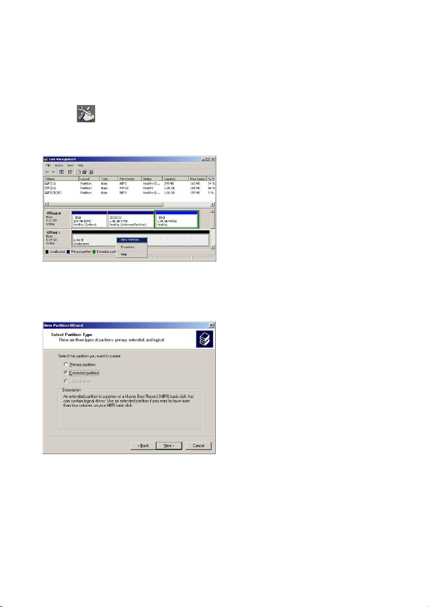
3-1-4. Disk Management
This chapter walks you through the hard drive formatting in DVR system when you install a brand
new hard disk. Please follow the steps below to format the hard disks.
1. Click icon to display the “Disk Management” interface.
2. Click the mouse right button on the new installing HDD, and select “New partition “item.
Fig. 3-1-4.1 Select “New Partition”
3. Press “Next” to start the format process.
4. Select “Extended partition “item and click “Next” button to continue.
Fig. 3-1-4.2 Select “Extended Partition”
5. Click “Next” to specify partition size.
6. Click “Finish “icon to complete the new partition wizard.
7. Click mouse right button on the new HDD again, and select “New Logical Drive”.
41
Page 42
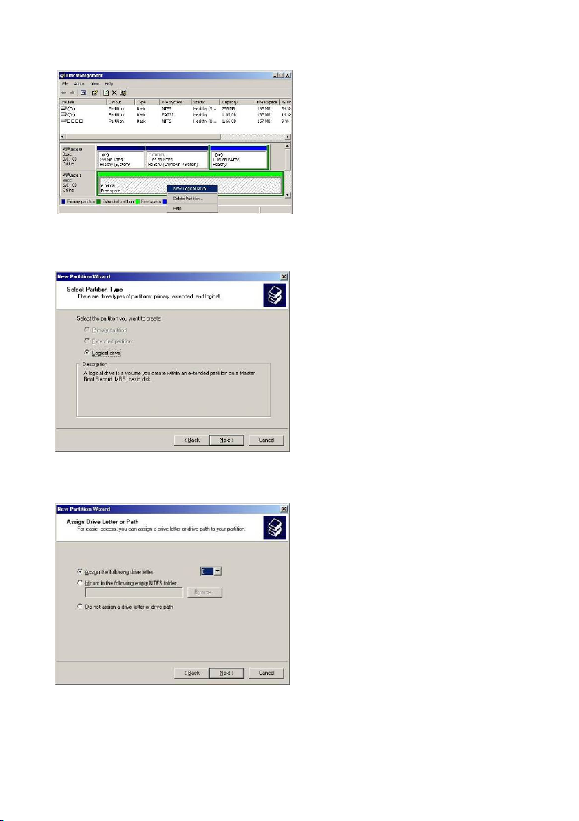
Fig. 3-1-4.3 Select “New Logical Drive”
8. Click “Next” to continue.
9. Select “Logical drive “partition type, and clicks “Next” to continue.
Fig. 3-1-4.4 Select “Logical drive”
10. Select “Assign the following drive letter “item, and click “Next” to continue.
Fig. 3-1-4.5 Select “Assign the following
drive letter”.
42
Page 43

11. Select “Format this partition with the following settings “item, and click “Next” to
continue.
Fig. 3-1-4.6 Select “Format this partition with the following
12. Click “Finish” to complete hard disk partition and format process.
13. Repeat Step 1-12 to format another Hard disk.
3-1-5. Setup Share Folders
This chapter will show you how to share the system folder (e.g. ClipPro folder) and to-be-view
video files for remote network users. Please follow up the steps below to setup system-sharing
folders.
1. Click icon from the system control panel screen to display “Shared Folders” interface.
2. Select “Shares “folder, and click the “Action” button form the top, then select the “ New “ and
“ File Share “ item to continue.
Fig. 3-1-5.1 ActionNewFile
43
Share
Page 44

3. While the system displays a “Create A Shared Folder Wizard”, please click “Next” button to
continue.
Fig. 3-1-5.2 Create a Shared Folder
4.
Please click the “Browse” button to select a folder which user wants to share, and fill in the
“Share name” section, then press “Next” button and follow the instruction to complete the
shared folder sharing.
Fig. 3-1-5.3 Browse a share folder
1. You MUST share the Disk (Not folder) for remote client when you using the
ezLANPlayback program to playback the Video playback via LAN.
2. You MUST share the Folder for backup the video clips to Remote HDD via LAN when using
the ezBackup program.
3. There is a user account for remote access (Backup and playback video clips via LAN). You
need to Login for remote access. The User name is “guest” and password is “Guest”.
44
Page 45

3-1-7. Adjust Volume Control
Please click the icon on the system control panel screen to adjust the system volume.
3-1-7. Saving System Information
To make the change effectively after modifying each DVR system configurations, user need to press
Fig. 3-1-6.1 Adjust Volume Control
the “Save System Setting” ( ) icon to complete the changes.
45
Page 46

3-2. DVR Main Program
3-2-1. System Configuration Diagram
46
Page 47
3-3. Program Overview
3-3-1. The main function description:
47
Page 48

 Loading...