

Page 1
Rev. 3-2-2012
CZ-537-IP IR Night V ision
Network PTZ
Cameras
Page 2

Contents
1 Instruction ..................................................................................................... 1
1.1 Safety Instructi ons ............................................................................ 1
1.2 Warnings ........................................................................................... 1
2 Feature .......................................................................................................... 2
2.1 Product Fe a t ur e s ............................................................................... 2
2.2 Specifications ................................................................................... 3
3 Installation Instruction .................................................................................. 4
4 Software Installation Instructions ................................................................. 6
4.1 Client User Instruction...................................................................... 6
4.2 Main Interface .................................................................................. 6
4.3 Toolbar .............................................................................................. 9
4.3.1 Image Quality ......................................................................11
4.3.2 OSD .................................................................................... 12
4.3.3 Shelte r ................................................................................ 12
4.3.4 Motion Detec tion ................................................................ 12
4.4 Setting............................................................................................. 13
4.4.1 Client Setup ........................................................................ 13
4.4.2 Video Switch Setting .......................................................... 13
4.4.3 Local User Management..................................................... 13
4.4.4 Automatic-Record .............................................................. 13
4.4.5 Playback ............................................................................. 14
4.4.6 Language Version ............................................................... 14
4.4.7 Full Scr e e n ......................................................................... 14
4.5 Device property .............................................................................. 14
4.5.1 Addr ess/Po rt ....................................................................... 15
4.5.2 DDNS ................................................................................. 15
4.5.3 PPPoE ................................................................................. 15
4.5.4 Multicast ............................................................................. 16
Page 3

4.5.5 E-Mail ................................................................................ 16
4.5.6 Date/Time ........................................................................... 16
4.5.7 Alarm In ............................................................................. 16
4.5.8 Alarm Out........................................................................... 17
4.5.9 PTZ..................................................................................... 17
4.5.10 Video Channel .................................................................. 17
4.5.11 Audio Channel .................................................................. 17
4.5.12 User Management............................................................. 17
4.5.13 Update .............................................................................. 18
4.6 LAN and WAN configuration ......................................................... 18
4.7 Application for DDNS .................................................................... 19
4.8 Router configuration ....................................................................... 19
4.9 IE mode .......................................................................................... 19
5 How to Use OSD Menu .............................................................................. 20
5.1 Basic operation of Main menu ........................................................ 20
5.2 Main Menu ..................................................................................... 21
5.2.1 Sy s tem Informa ti on ............................................................ 22
5.2.2 Addr ess Setting ................................................................... 22
5.2.3 Motion ................................................................................ 23
5.2.4 Patte r ns ............................................................................... 24
5.2.5 Camera Setup ..................................................................... 25
5.2.6 Cruise Setting ..................................................................... 35
5.2.7 IR Setti ng ........................................................................... 35
5.2.8 Display Setup ..................................................................... 36
5.2.9 Restore Factory Default ...................................................... 36
5.2.10 Rebo ot S ystem.................................................................. 36
6 T r oub l e Shooting ........................................................................................ 37
7 Fast Control Chart ...................................................................................... 38
Appendix I DIP Switch Setup ........................................................................ 39
Page 4

1
1 Instruction
These series of products can be widely used in intelligent building, bank
security, urban roads, airport terminals and bus stations, and also are able to
satisfy various demands from any sq uare and activities o ccas ion.
1.1 Safety Instructions
Make sure to read the use’s manual before using the product.
Always confirm to national and local safety codes during installation.
Only qualified and experienced person can carry on this installation and
maintenance.
Use reliable tools, otherwise may lead to dangerous incidents.
Make sure that the environmental conditions meet the installation
requirements for this product.
Please check the space and toughness of the site before installing. It
should be able to bear 4 times the weight of the dome and its
accessories.
Please keep all th e original dome p ackage material s for futu re repackin g
and transporting.
1.2 W arnin gs
Do not install this speed dome in hazardous places where combustible or
explosive material s ar e s tored or used.
Do not place the machine on shaking desk.
Make sure no uncertain object or fluid substances get inside the unit.
Do not turn power on before finishing installation.
Do not disassembl e any part of the items.
Use soft towel to clean the down cover when necessary, do not use
caustic detergent.
To protect CCD, avoid facing the camera directly to the strong light.
To prevent damage, do not drop the unit or subject to strong shock or
Page 5

2
vibration.
2 Feature
2.1 Product Featur es
* OSD menu;
* 254 presets;
* Auto flip;
* Proportional zoom;
* Day & night function;
* RS485 communication;
* Protocol and baud rate auto detected;
* Soft address enables to set up the address and number of the camera;
* Multiple scans: frame scan (speed adjustable); 4 patterns; 3 tours; 360°
random scan; 360° continuous scan; parking action; power up action; etc.
IP Function
* H.264 video compression format;
* Support CIF/D1 format;
* Support mobile, RS485, alarm, intercom and monitor interface;
* Support SMTP, could send the picture in the accident place when alarm;
* Built-in Web Server, support IE browser surveillance, configuration and
update;
* Motion detection, can trigger automatic recording, fixed time recording and
manual recording;
* OSD menu is provided to display the status of camera and to configure the
functions interactively.
* User accession permission should be setting.
Page 6

3
2.2 Specifications
Model IR IP Mini Variable Speed Dome Camera
Help Selection Ceiling
Power Supply DC12V/2A 50Hz/60Hz
Power ≤15W
Pan Speed 0.5°~50°/ sec
Tilt Speed 0.5°~30°/ sec
Pan Ran ge 360°continuous
Tilt Range 0°~90° auto flip
Preset 254
Pan Scan
frame scan; 360° random scan; 360°
continuous scan;
Pattern 4
Cruise 3
OSD Menu Chinese/English
IR Illumination ON/OFF (option)
IR Distance ≥20m
Baud Rate 2400bps,4800bps,9600bps auto adaptive
Video Compression Format H.264
Video Format CIF/D1
T r a nsmission Protocol
TCP, UDP, IP, HTTP, FTP, SMTP, DHCP,
DNS
Access Mode IE, Mobile, Client
Protocol PELCO-D, PELCO-P
Communication RS485
Address 255
Work Temperature -10°C~40°C
Page 7
4
Camera Module
Support 10X Samsung, Sony camera
module,
compatible 38*38 CCD with
fixed focus lens.
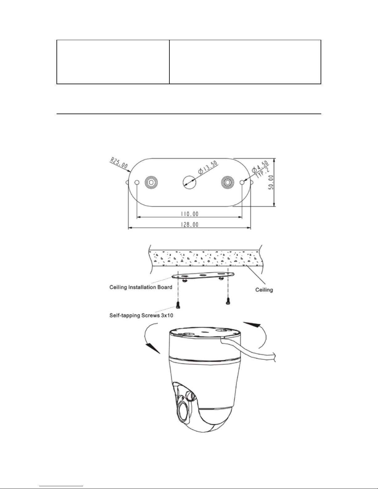
3 Installation Instruction
3.1 Installation
A. Fixed the ceiling installation board with supplied screws. The board
dimension as shows:
B. Install th e dome camera as shows:
Page 8
5
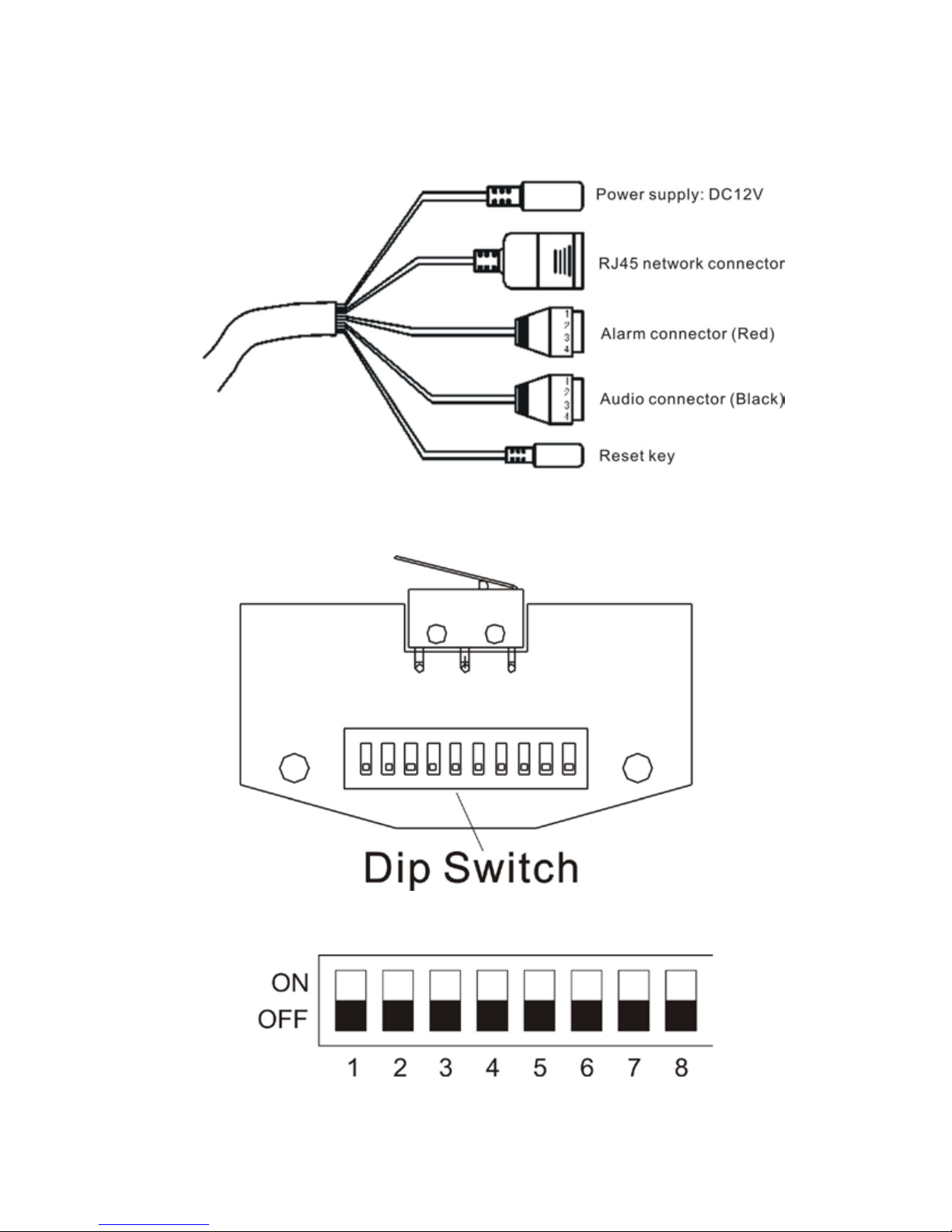
3.2 System Connection
3.3 Dip Switch Setup
Dip Switch as follows:
Notice: Dip Switch Address Setup see appendix I
Page 9

6
4 Software Installation Instructions
4.1 Client User Instruction
System requirement
Operating System: Windows 2000/XP/Vista
Processor: Intel Pentium III, 1G or Higher (Pentium IV, 2G or
Higher recommended)
RAM: 256 MB or more
Color Monitor: At least DirectX 8.1 or higher and 32M Display
storage
HD: More than 40G
Double-click the Program of Client Software Package to install the software:
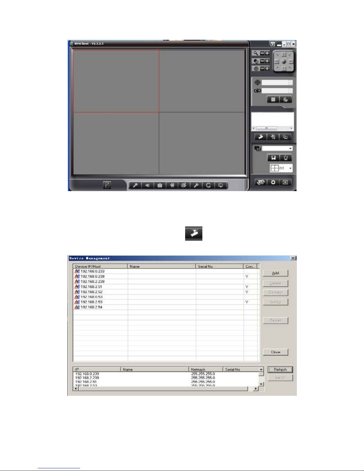
4.2 Main Interface
Double click
to run the program, and then enter the user
information, default is blank. Change the user information see
<Setup>→<Administration>.
Main Interface:
Page 10
7
First user should add the IP/ Host name in the client software to open the
surveillance picture. Steps are following:
1). Click th e right side <Devices>button
, will pop up:
Note: If t he devic e is not in t he same n etwor k segment, Client could aut o
search but cannot connected. Modify the IP device’s IP and gateway, or
Page 11
8
add one mo re IP in the same network segment.
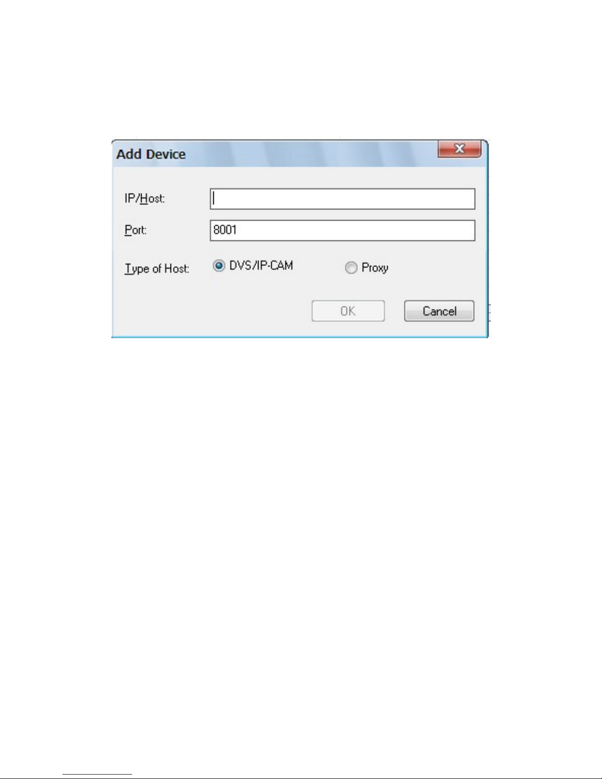
2). For the device cannot search with network, user could add IP/Host
manually. Click <Add>, the following will pop out:
Note: Access to the Video/transfer server program, the Host chooses
“Proxy”.
3). Input the IP/Host, for example, the IP/Host is testdvs3322.org, and port is
8001, the Host chooses DVS/IP CAM, click<OK>.
4). Double click the d evice list , and then pop out the connected window, input
the administrative and password, the default is “Admin”.
5). Click <Connect>, and then the main interface on the right will show the
device address, chooses channel 1, press left key and drag it to the left window.
The monitor picture show out.
Page 12

9
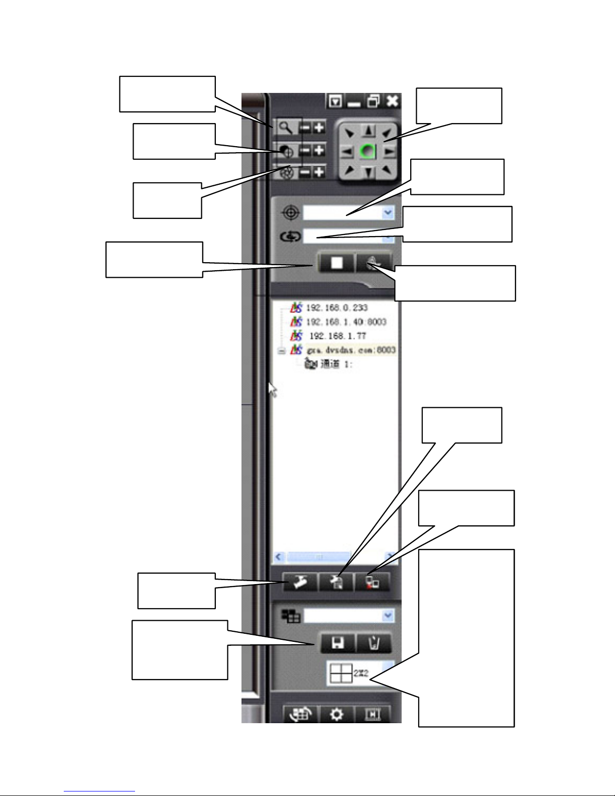
4.3 Toolbar
From Left to right: Information; Talkback; Sound; Snapshot; Record; Color;
Setup; Flip/Rotate; and Open.
Zoom
Focus
Iris
Preset Point
Cruise Tracks
Page 13
10
Navigation
Zoom In/Out
Focus+/-
Iris+/-
Preset Point
Edit Cruise-track
Stop Cruise
Devices
Property
Disconnect
Save/Delete
Scene
Cruise Tracks
Display
channels,
support
1/4/6/8/9/12/
16/20/25/30
window
display
Page 14
11
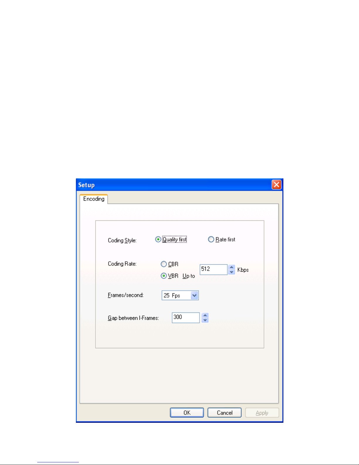
4.3.1 Image Quality
Image Quality could set Stream Style, Coding Style, Frame, Gaps between
I-Frames.
<Coding Style>: ① Quality first; ② Rate first
<Up limit>: When the cod ing stale is Rate first, the actual coding would
not exceed the value. The default value is 1024kps.
<Frame rate>: It means the frames per second in the video. The value
range from 1~25, the default value is 22 Fps.
<I Frame Interval>: I n the process of video tr ansmission, one I frame in
per 100 frames. The default value is 100.
Page 15
12
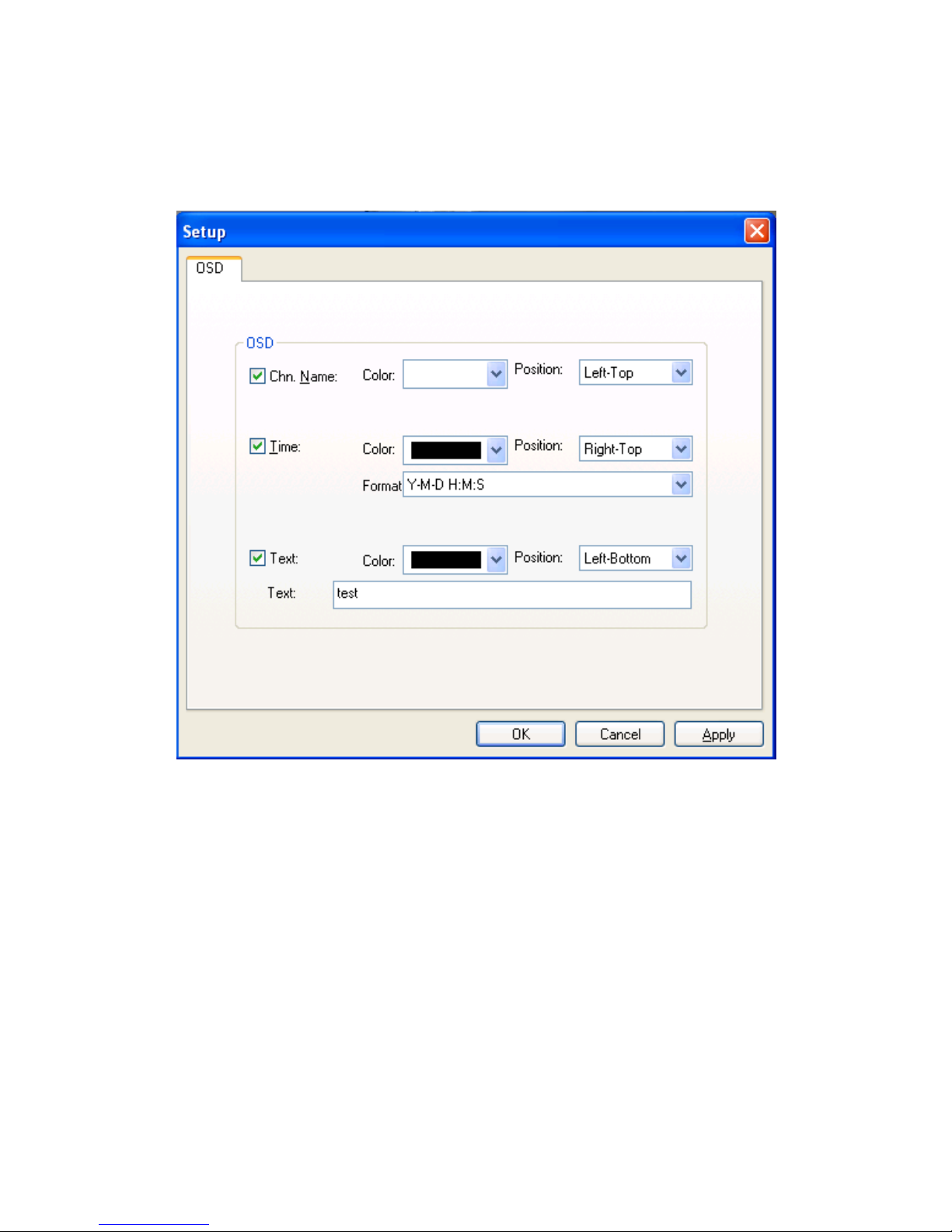
4.3.2 OSD
OSD Menu could set channel information, time, the color and the position of
text.
4.3.3 She lt e r
Shelter means cover one part of picture in the monitor screen. Hold <Ctrl> to
select shelter area, click <Clear> key to clear the shelt er.
4.3.4 Motio n De t e c t ion
<Motion detection setup>: Hold <Ctrl> to select the detection area, at
most 4 areas coul d be set.
<Sensitivity>: The value is larger the sensitivity is better.
<Valid period of time>: Setup motion detection of the alarm durable
time and the triggering alarm time.
<Alarm handling ways>: Sound, inform user and send Email.
Page 16

13
<Output to Channel>: You could choose the other channels except the
nominated channel to display the motion detection result.
4.4 Setting
4.4.1 Client Setup
Click
, save the video path, alarm trigger recording time, alarm
playback sound , and the scen e you exis t last ti me. It coul d be set several video
paths, the default is saving in the first path, when the first path is full, and it
will save in the next path.
4.4.2 Video Switch Setting
Video Switch setting could change the picture automatically on the same
screen to different devices or channel. Click <Pages>, turn up and down to
increase or decr ease the pages. Click<Stay> turn up and down to increase or
decrease the time for staying. Click the layout window to set the display mode,
press and hold the left mouse button to drag the right side of the channel to be
displayed, double-click the right side of the channel to r emove it.
4.4.3 Local User Management
User should use password when login, the initial password is
empty
. User can
increase the corresponding user name and password and operating authority.
If the screen in lock or full-screen mod e should use password when exit.
4.4.4 Automatic-Record
Automatic-Record Setting is automatically recording a piece of time for
equipment, video file path save in page setup
<Client Setup>
.Start
automatic-record, the cl ient kept the upper right co rner
will be flashing
green light.
Page 17

14
4.4.5 Playback
Click
pop out the window, you could find the video file from the
saved catalogue o r event. Double click the video file to play.
4.4.6 Lan guage Version
The software support Chinese and English, click pop
to switch.
4.4.7 Full Screen
Click
change to full screen mode, all actio n will be locked under
this mode, input administrator password when quit. Click the right button to
pop:
4.5 Device property
Click or choose IP address in device list, click <Property> by
right key to pop dialog, setup or adjust IP address、DDN、PPPoE、broadcast
configuration、user management、update online, etc .
Choose to pop alarm info
Page 18

15
4.5.1 Address/Port
Default IP address:192.168.0.233, subnet mask:255.255.255.0 ,
gateway:192.168.0.1, service port 8001. After change, system will register
you restart your device to valid the setup. Change service name not need
restart.
Notice 1: IP address will valid only after device restart.
Notice 2: When link 2 or more devices, need change related IP address
and phys ical address.
Notice 3: Outer net visit need mapping the service port, refer router
configuration p art. DNS server needs cha nge to current DNS IP address
also.
4.5.2 DDNS
DDNS mean dynamic DNS, for unfixed IP domain name mapping. Thi s clien t
software support peanut shell and 3322 DDNS Service. Just apply your
domain name in the proper network station (refer to Part 4.7) then click
<OK> in the pop dialog, the DDNS will valid.
<DDNS Service Provider>: Now support www.oray.net and
www.3322.org.
<User Name>: One account can apply different domain name, the
provider request not same.
<Password>: The password is that you apply the domain name setting.
<Dynamic Domain Name>: According to domain integrated address.
4.5.3 PPPoE
The client software allows PPPoE. Link the device to phone line through
modem, dial to internet. User can visit the monitor picture by internet from
long distance. Choose PPPoE in the dialog then input user name and password
then click <OK>.
Page 19

16
4.5.4 Multicast
Use set device as need ed to realize th e mul ticast function.
4.5.5 E-Mail
When choos e mail ser vice, t he d e vice will sen d even t rep o rt an d pictu re to the
appointed mailbox when alarm or Motion Detection triggered.
<SMTP Server>: Follow your mailbox hints for related setup.
<SMTP Port>: Default is 25.
<Sender’s Account>: Need according to the SMTP service if your
mailbox support.
<User Account>: When enter the user account, it could auto catch
account information that has been used.
<Password>: Account related password.
<Receiver’s Account>: Any mailbox which can receive mail.
Click<Send A Test Mail> after setup to confirm your action.
Notice: Fo r outlook or fox mail user, need set the s ender accou nt to valid
the funct ion.
4.5.6 Date/Time
Adjust device date, time. Click <Same with PC> to sync hronous with PC.
4.5.7 Alarm In
<Channel>: Allow setup name for choosing channel.
<Actions take to response to alarm>: Sound alarm, notice client and
send e-mail.
<Output to >: Setup output chann e l .
<PTZ linkage>: Ther e are 3 kinds of linkage: separate, preset and cruise.
Monitor channel must be appointed when choose preset or cruise mode.
<Valid period of ti me>: Setup alarm input time period . "+" mean valid
period, "-" mean except the period.
Page 20

17
4.5.8 Alarm Out
<Channel>: Allow setup name for choosing channel
<Valid period of time>: Setup alarm output time period. + mean valid
period, - mean except the period
4.5.9 PTZ
<Video Channel>: Choose video channel.
<Address>: Matching the PTZ address with protocol.
<Protocol>: Support Pelco-D & Pelco-P, default is Pelco-D.
<Step Length>: Range 1~64, default 32.High speed will make the
control hard; suggest under 32 for high speed dome.
<Comm Setting>: Set baud rate, data bit, stop bit, verify bit.
4.5.10 Video Channe l
<Channel>: Choose the channel.
<Name>: Setup the channel name.
<Resolution>: 4 kinds: QCIF / CIF / Half_D1 / D1.
<PAL/NTSC>: Choose PAL or NTSC.
4.5.11 Audio Channel
<Channel Number>: Choose the channe l No.
<Bits Width>: 8bits / 16bits / 32bits for optional.
< Sampling Rate >: The effect will better with frequen cy increase.
<Compression>: Choose different mode to compress audio steam (about
10 times).
Notice: Suggest keep the default setting in normal. Just click
open t a lkback and voice function.
4.5.12 User Management
User management is use to add, delete or modify user name and password,
and setup corresponding authority. User name can only be English character
Page 21

18
or number, Chinese is no supported, maximum length of user name or
password is 10 characters.
User is separated into four classes:
<Normal User>: Admit to brown monitor image, no authority to setup
device and manage user.
<Junior User>: Admit to con trol PTZ/Lens, no authority to setup device.
<Senior User>: Admit to setup device, no authority to manage user
<Administrator>: Authorized to setup device and manage user. The
default
Administrator id is admin, password is admin, the id is no allowed to delete.
4.5.13 Update
User can update device local by client or long distance through IE. Device
will auto restart after upgrade. User can check current version no. here.
<Current version >: Display current version, not allow edit.
<File to upload>: Click <Open>find the file then click<Upload>, the
following dialog will show the progress. The device will auto restart after
upgrade, not shut off during the process.
4.6 LAN and WAN configuration
(1) LAN automatically search
Run DVS Client, Click
, the video server in the local LAN will
appear in the d evice list. Onl y PC and video server in same network segmen t
can connect.
If there are no device in the device list, make sure the following question:
① I f D V S i s al ready pow ered?
② I f D V S and PC have b een no rm al connected? I f yes, the l i gh t wi l l be l ong
bright or fl a s hing .
③ If PC has firewall working? If yes, should do it again after closing the
Page 22

19
firewall.
(2) WAN manually search
If users want to login in another subnet, th e d evice can not automatically be
searched. The video device should be manually added as the following steps:
① Reg i ster D D N S serv i ces f ro m a D D N S service provider. After applications
a domain name will be assigned, and an account number and password will be
obtained.
② Click mouse ri ght key in device l i st up item, choose < Property> →< D D N S>
set your domain info.
③ W hen I n ternet I P i s changed . The d evi ce will automatically tell DDNS
server its new Internet IP.
④ Users only input domain in the network browser can run Client.
4.7 Application for DDNS
Normally users u se dynamic IP address in the intern et. User can use a static
hostname instead of a dynamic IP address to monitor Lan device image. In
this way, user should register a domain name and obtain a password. The
device supports www.3322.org and www.dyndns.org, users can login it and
register the domain, after doing it, set your domain info.
4.8 Router configuration
Routers must be set to enable a PC TCP connecting to the device. Routers use
port number to decide which device request is allowed, this function is port
transmitting or virtual services.
4.9 IE mode
When first visit device through IE, user n eed add http:// by manual to pop the
following dialog:
Page 23

20
Click【
】 download the client and
control , then install it. Then input user name and password
(default is admin) can get monitor page.
5 How to Use OSD Menu
5.1 Basic operation of Main menu
♦ Go Preset #95 enter into main menu.
♦ Using “Iris open” and “Iris close” to confirm or exit main menu.
♦ Using “UP/DOWN” keys or jo ystick to move cursor to sub-menu, press
“Iris open” to enter into menu.
♦ Using “UP/DOWN” keys or joystick to move cursor to the function and
press “Iris open” to choose the function.
♦ Using “UP/DOWN” keys or joystick to set up and press “Iris open” to
save.
Page 24

21
♦ Move the cursor to “BACK” and press “Iris open” to back to main
menu.
5.2 Main Menu
Call preset # 95 enter the main menu:
<SYSTEM INFORMATION>: Shows system information.
<ADDR SETTING>: Select and s etup Soft/Hard address.
<MOTION>: Setup for motion related settings.
<PATTERNS>: Setup for Patterns.
<CAMERA>: Configure Camera related functions and data.
<CRUISE SETTING>: Setup presets scan.
<IR SETTING>: Setting IR ON/OFF SENS.
<DISPLAY SETUP>: Enable / Disable of OSD display on main screen.
<RESTORE FACTORY DEFAULT>: Resto r e factory settings.
<REBOOT SYSTEM>: Reboot the system.
MAIN MENU
SYSTEM INFORMATION
ADDR SETTING
MOTION
PATTERNS
CAMERA
CRUISE SETTING
IR SETTING
DISPLAY SETUP
RESTORE FACTORY DEFAULT
REBOOT SYSTEM
EXIT
Page 25

22
5.2.1 System Information
<COM>: Shows current Baud rate.
<ADDRESS>: Shows current Camera ID for PTZ control, 0~255.
<SOFTWARE VERSION>: Shows current s oftware version of camera.
Notice: The sys tem information can not be changed.
5.2.2 Address Setting
<ADDR TYPE>: Choose the address type (Hard/Soft Add), when you
choose soft t ype, the user can setup the address by remote access.
<ADDR SOFT>: Setup soft address. The camera ID can be set from
0~255.
<ADDR HARD>: Setup hard address. It can be changed by DIP Switch.
Notice: Please reboot the dome camera after reset the camera ID.
ADDR SETTING
ADDR TYPE HARD
ADDR SOFT 1
ADDR HARD 1
BACK
EXIT
SYSTEM INFORMATION
COM 2400, N, 8, 1
ADDRESS 1
SOFTWARE VERSION V5.2
BACK
EXIT
Page 26

23
5.2.3 Motion
Frame Scan
<SET SCAN POSITION>: Set up scan range between two positions
(Left/Right extreme position).
<CLEAR FR AME SCAN>: Deletes frame scan.
5.2.3.1 Set Sc a n P os it ion
(1) Move the cursor to <SET SCAN POSITION> and enter below interface.
(2) Move the cursor to choose the extreme position of preset by using
“Left/Right” keys or joystick of your controller, then press “Iris Open” to
SET FRAME SCAN
LEFT LIMIT POSITION
IRIS OPEN TO CONTINUE
FRAME SCAN
SET SCAN POSITION
CLE AR FR AME SCAN
FRAME SCAN SPEED 16
BACK
EXIT
MOTION
FRAME SCAN
POWER UP NONE
PARK TIME 15S
PARK ACTION NONE
BACK
EXIT
Page 27

24
enter below interface:
5.2.3.2 Clear Frame Scan
Move the cursor to “Clear Frame Scan” to enter, then press “Iris Open” to
delete the extreme positions.
5.2.4 Patterns
<PATTERN NUMBER>: Set Pattern number (1~4).
<PROGRAM PATTERN>: Pattern scan program.
<CLEAR CURRENT PATTERN>: Deletes data in current pattern.
PATTERNS
PATTERN NUMBER 1
PROGRAM PAT TERN
CLEAR CURRENT PATTERN
CLEAR ALL P ATTERN
BACK
EXIT
SET FRAME SCAN
RIGHT LIMIT POSITION
IRIS OPEN TO CONTINUE
CLE AR FR AME SCAN
IRIS OPEN TO CONTINUE
Page 28

25
5.2.5 Camera Setup
We are using Samsung SDM-100P camera to explain below operation.
Notice: “Up/Down” keys for option, “Left/Right” keys for details, “Iris
Open” for sub-menu.
<CAMERA LABEL>: press “Iris Open” to enter sub-menu and edit
camera label.
Using cursor to s elect the letter, then press “Iris Open” key to save th e s etup.
CAMERA LABEL
ABCDEFGHIJKLMNO
PQRSTUVWXYZ a b c d
e f g h I j k l m no p q r s
t u v w x y z01234567
89 ( ) < > - / # *!? , .
Clean Position Exit
MAIN MENU
CAMERA LABEL OFF
WHITE BALANCE AUTO
BLC OFF
AUTO DETECTION OFF
FOCUS
EXPOSURE
ADDITIONAL MENU
BACK
EXIT
Page 29

26
<WHITE BALANCE>:
WB Mode: Auto Trace / Manual / Auto
(1) Auto Trace : Indoor/Outdoor, The camera can automatically adjust ambient
light from1800K~10500K(Indoor: 3000~10,500K; Outdoor: 1,800~10,500K),
to ensure the most nature image effect.
(2) Manual: C lo s e auto WB, adjust Red and Bl ue level manually.
Red adjust range: 0~100 Blue adjust range: 0~100
(3) Auto BW: This mode is the most accurate and reliable for most places.
<BACKLIGHT COMPENSATION>
Backlight: High/Middle/Lo w/Off
<MOTION DETECTION>
Match the Alarm sensor input to one of preset positions. If an external sensor
is activated, camera will move to corresponding preset position when this item
is predefined.
MANUAL WB
RED 30…|..……….
BLUE 41…..…|…….
EXIT
AUTO TRACE WB
AUTO TRACE WB MODE OUTDOOR
EXIT
Page 30

27
Alarm: On/Off Region:1~4 Region Mode: On / Off
<FOCUS>
♦ <MODE>: Auto, Manual, One-off Auto focus. Press “Iris Open” to enter
sub-menu
One-off auto focus: Once the image zoom changes, the camera will
automaticall y focus and fix the stat us till the image change agai n.
Notice: Do not use Auto Focus under the bel ow conditions.
The target is too dark (such as black clothes or curtains).
FOCUS
MODE AUTO
ZOOM TRACE MODE ON
ZOOM TRACE SPEED FAST
DIGITAL ZOOM ON
SHOW ZOOM OFF
INITIAL ZOOM POSITION OFF
LENS INITIALIZATION
EXIT
MOTION DETECTION
ALARM OFF
SELECT REGION 1
REGION MODE ON
TOP
20…|..……….
BOTTOM 25….…|…….
LEFT 20…|.……….
RIGHT
40….……|….
EXIT
Page 31

28
The target is very s mooth( like car surface)
The brightnes s contrast of the target is not very clear.
Too strong high light or back light.
Too high contrast.
Some shade in front of the target.
① Auto mode setup:
Using the direction keys to enlarge or downsize, press “Iris/Open” key to
back.
② One-off Auto focus and Manual fo cus Adjus tment:
♦ <ZOOM TRACE MODE>:
Manual Focus: Off. Auto and One-off Auto Focus: On / Off.
♦ <ZOOM TRACE SPEED>: Fast/Slow.
♦ <DIGITAL ZOOM>: On / Off, range: X2~X10.
♦ <SHOW ZOOM>: On / Off.
♦ <INITIAL ZOOM POSITION>: Using direction keys to move the
SETUP ZOOM
↑ ZOOM IN ↓ ZOOM OUT
BACK: PRESS “SET” KEY.
SETUP ZOOM
↑ ZOOM IN ↓
ZOOM OUT
←
NEAR → FAR
BACK: PRESS “SET” KEY.
DIGITAL ZOOM
DIGITAL ZOOM X2
EXIT
Page 32

29
cursor to “On”, then press “Iris Open” to set up.
Zoom Range: X1~X1 0
♦ <LENS INITIALIZATION>: press “Iris open/Set” key to initialize the
lens.
♦ <EXPOSURE>:
<BRIGHTNESS>: Brightness Range: 0~100.
<IRIS>: Auto/ Manual. Press “Iris Open” to enter into manual setup.
If the number of iris is set to higher, the image will be brighter.
<SHUTTER > :Shutter Mode: Flicker / Manual / Auto
The shutter speed of Anti-flash is 1/100 (NTSC), 1/120 (PAL)
Manual mode setting (PAL):2X、4X、6X、8X、10X、12X、14X、16X、
MANUAL IRIS
IRIS 100….………|
EXIT
EXPOSURE
BRIGHTNESS 25….…|…….
IRIS AUTO
SHUTTER ——
AGC OFF
SSNR OFF
SENS-UP OFF
EXIT
INITIAL ZOOM POSITION
INITIAL ZOOM POSITION X1
EXIT
Page 33

30
24X、32X、64X、128X、1/120000、1/60000、1/30000、1/10000、/1/7000、
1/5000、1/2500、1/1600、1/1000、1/700、1/500、1/250、1/100、1/50.
Notice: Auto shutter setting only for manual iris mode.
<AGC>: High / Middle / Off / Manual
Enhances image brightness automatically in case that luminance level of
image signal is too low.
Range: 5-41
<SSNR>: High / Middle / Lo w / Off
Enhances images by reducing noises when gain level of images too high.
<SENS-UP>: Auto / Off
Adjust CCD exposure time.
Auto mode setting:2X、4X、6X、8X、10X、12X、14X、16X、24X、32X、
64X、128X.
SENS-UP
SENS UP X4
EXIT
AGC
LEVEL 5
EXIT
MANUAL SHUTTER
SHUTTER 1/50
EXIT
Page 34

31
♦ <ADDITIONAL MENU>:
① USER PRESET SETUP: On / Off
<USER PRESET NUMBER>: 8 groups user preset number, 1~8.
<USER PRESET MODE>: use direction keys to “On” and press
“Iris/Open” t o setup.
USER PRESET MODE
FOCUS
EXPOSURE
OTHER
EXIT
USER PRESET
USER PRESET NUMBER NO 1
USER PRESET MODE OFF
SAV E
CLEAR
EXIT
PRESET NOT SETUP.
ADDITIONAL MENU
USER PRESET SETUP OFF
PRIVACY ZONE MASK OFF
DAY & NIGHT AUTO 1
SYNC. SYSTEM INTERNAL
IMAGE ADJUSTMENT
RE-BOOT
EXIT
Page 35

32
<Focus>: Using direction keys to “Fo cus” and press “Iris/Open ” key to
set up.
<OTHER>: refer to below details.
OTHER
CAMERA TYPE OFF
BW AUTO TRACE BW
BLC OFF
MOTION DETECTION OFF
PRIVACY MASK OFF
DAY & NIGHT OUTER
HORIZONTAL FLIP OFF
VERTICAL FLIP OFF
EXIT
FOCUS
MODE AUTO
ZOOM TRACE MODE ON
ZOOM TRACE SPEED FAST
DIGITAL ZOOM ON
SHOW ZOOM OFF
EXIT
Page 36

33
② PRIVACY MASK:
<GROUP SELECTION>: 1~ 8
<AREA SELECTION>: 1~ 4 zones / group
<ZONE MODE>: On / Off
<COLOR>: color, range of privacy zone is 0~100.
<TOP>: ordinate pos it ion on the top of zone.
<BOTTOM>: ordinate position on the bottom.
<LEFT>: horizontal abscissa position on the left side.
<RIGHT>: horizontal abscissa position on the left side.
③ DAY/NIGHT: Day and Night function. Auto 1/ Auto 2 / Outer/ Color/
B&W mode.
<B&W MODE>: suit for night work.
<COLOR MODE>: suit for daytime.
<AUTO MODE>: change day and night mode automatically according
to the environment illumination. Auto 1 is faster than Auto 2.
④ SYNCHRONOUS MODE: inter nal, unchangeab le.
PRIVACY MASK
GROUP SELECTION 1
AREA SELECTION 1
ZONE MODE OFF
COLOR 50…|..……….
TOP 50…|..……….
BOTTOM 104….…|…….
LEFT 50…|.……….
RIGHT 98……|……
EXIT
Page 37

34
⑤ IMAGE ADJUSTMENT:
<FREEZE>: Camera starts freezi ng the image of start point, as soon as
camera stops at p reset end point, camera starts display live images.
<HORIZONTAL FLIP>: image will flip 180°when you start up. Normal
when shutdown.
<VERTICAL FLIP>: image will flip 180°when you start up, and normal
when shutdown.
<SHARPNESS>: adjust the sharpness of the edges. Range: 0~31.
<HUE>: adjust the image hue, range: 0~100.
⑥ RE-BOOT: restart the camera.
⑦ EXIT: exit ca mer a menu.
SHARPNESS
SHARPNESS 8…|.……….
EXIT
IMAGE ADJUSTMENT
FREEZE OFF
HORIZONTAL FLIP OFF
VERTICAL FLIP OFF
SHARPNESS ON
HUE 50….…|…….
EXIT
Page 38

35
5.2.6 Cruise Setting
<Dwell Time (Secs)>: preset cruise dwell time, range:5~250 Sec.
<Preset 1~20>: default is ON, use direction key of CCTV Tester to
modify preset and confirm by press “Iris/Open” key.
5.2.7 IR Setting
<IR MODE>: IR light’s control mode, AUTO/ON/OFF could be chosen.
<IR ON SENS>: IR ON automatically when current IR light value
higher than setting IR light value. 81~254 could be optional.
<IR OFF SENS>: IR OFF automatically when current IR light value
IR SETTING
IR MODE AUTO
IR ON SENS 110
IR OFF SENS 90
BACK
EXIT
CURRENT LEVEL 23
CRUISE SETTING
PRESET11 ON
PRESET12 ON
PRESET13 ON
PRESET14 ON
PRESET15 ON
PRESET16 ON
PRESET17 ON
PRESET18 ON
PRESET19 ON
PRESET20 ON
BACK
CRUISE SETTING
DWELL TIME (SECS) 8
PRESET 1 ON
PRESET 2 ON
PRESET 3 ON
PRESET 4 ON
PRESET 5 ON
PRESET 6 ON
PRESET 7 ON
PRESET 8 ON
PRESET 9 ON
PRESET10 ON
Page 39

36
lower than setting IR value. 81~254 could be optional.
<CURRENT LEVEL>: the current IR light value.
Use direction key of CCTV Tester to modify preset and confirm by press
“Iris/Open” key.
5.2.8 Display Setup
< PRESET LABEL>: Show or hide presetting labels.
<P/T DEG>: Show or hide camera pan/tilt labels. The coordinates refer
to the monitor centre.
<BRIGHT DATA>: Show or hide IR light value.
Use direction key of CCTV Tester to modify preset and confirm by press
“Iris/Open” key.
5.2.9 Restore Factory Default
Move cursor to <RESTORE FACTORY DEFAULT> and press “Iris/Open”
to restore facto ry default.
5.2.10 Reboot System
Move cursor to <REBOOT SYSTEM> and press “Iris/Open” to reboot the
system. Easy to change the Soft/Hard address by remote and no need to power
off.
DISPLAY SETUP
PRESET LABEL ON
P/T DEG ON
BRIGHT DATA ON
BACK
EXIT
Page 40

37
6 Trouble Shooting
Troubles Reason Solution
No action
when power on
1. The power supply DC12V
is not
connected correctly.
2. The fuse is broken.
1. Correct the connection.
2. Check the power supply is
connected, or confirms if
the plug connects well.
3. Replace the fuse.
Self-testing
and image are
normal but the
dome is out of
control
1. The dome DIP switch setting is
incorrect.
2. RS485 cable is disconnected or
reversed.
3. Incorrect RS485 cable wiring.
1. Reset the DIP Switch
according to the DIP switch
chart.
2. Check 485 bus controls.
3. Check the wiring.
4. Check the control device.
Some function
is out of
control
1. RS485 communication signal is not
balance.
2. Control protocol is not compatible.
3.RS485 is disturbed
1.Connect 120Ω balance
resistance.
2. Reset protocol.
3.Eliminate the interference
sources
Unclear image
1. Focus is in manual state.
2. Extreme zoom magnification.
3. Dome cover is dirty.
1. Reset the focus mode to Auto.
2. Downsize zoom proportion
3. Clean the dome cover.
No night
vision
1. Camera is in Color state.
2. Backlight on the top or back of the
dome camera
1. Reset the day/night function
to Auto.
2.Remov
e the direct light
source.
Page 41

38
7 Fast Control Chart
Special Preset Function
CALL + #95 Access main menu
CALL + #82 Start frame scan function
CALL + #83 Clear all Presets
CALL + #84 Start pattern 1
CALL + #85 Start pattern 2
CALL + #86 Start pattern 3
CALL + #87 Start pattern 4
CALL + #88 Start preset #1~#10 cruise
CALL + #89 Start preset #11~#20 cruise
CALL + #99 Start preset #1~#20 cruise
Main Menu CALL #96+PRESET
Choose different camera module
and PAL/NTSC
CALL + #92 Start 360° random scan
CALL + #98 Start 360° Continuous scan
Page 42

39
Appendix I DIP Switch Setup
K1 DIP switch is an address switch, consist of 8 number, use 8421 binary
code, max 255 address. When the switch is in the “ON” position, the number
from 1~8 co rrespond ing to 1, 2, 4, 8, 16, 32, 64, 128. For example, if you set
1, 3, 5, 7 switch to the “ON” position, the corresponding address will be
1+4+16+64=85. please refer to below details.
DIP switch
Address
K1 ID Switch
(number 1- number 8)
DIP switch
Address
K1 ID Switch
(number 1- number 8)
1 2 3 4 5 6 7 8 1 2 3 4 5 6 7 8
1 1 0 0 0 0 0 0 0 2 0 1 0 0 0 0 0 0
3 1 1 0 0 0 0 0 0 4 0 0 1 0 0 0 0 0
5 1 0 1 0 0 0 0 0 6 0 1 1 0 0 0 0 0
7 1 1 1 0 0 0 0 0 8 0 0 0 1 0 0 0 0
9 1 0 0 1 0 0 0 0 10 0 1 0 1 0 0 0 0
11 1 1 0 1 0 0 0 0 12 0 0 1 1 0 0 0 0
13 1 0 1 1 0 0 0 0 14 0 1 1 1 0 0 0 0
15 1 1 1 1 0 0 0 0 16 0 0 0 0 1 0 0 0
17 1 0 0 0 1 0 0 0 18 0 1 0 0 1 0 0 0
19 1 1 0 0 1 0 0 0 20 0 0 1 0 1 0 0 0
21 1 0 1 0 1 0 0 0 22 0 1 1 0 1 0 0 0
23 1 1 1 0 1 0 0 0 24 0 0 0 1 1 0 0 0
25 1 0 0 1 1 0 0 0 26 0 1 0 1 1 0 0 0
27 1 1 0 1 1 0 0 0 28 0 0 1 1 1 0 0 0
29 1 0 1 1 1 0 0 0 30 0 1 1 1 1 0 0 0
31 1 1 1 1 1 0 0 0 32 0 0 0 0 0 1 0 0
33 1 0 0 0 0 1 0 0 34 0 1 0 0 0 1 0 0
35 1 1 0 0 0 1 0 0 36 0 0 1 0 0 1 0 0
Page 43

40
37 1 0 1 0 0 1 0 0 38 0 1 1 0 0 1 0 0
39 1 1 1 0 0 1 0 0 40 0 0 0 1 0 1 0 0
41 1 0 0 1 0 1 0 0 42 0 1 0 1 0 1 0 0
43 1 1 0 1 0 1 0 0 44 0 0 1 1 0 1 0 0
45 1 0 1 1 0 1 0 0 46 0 1 1 1 0 1 0 0
47 1 1 1 1 0 1 0 0 48 0 0 0 0 1 1 0 0
49 1 0 0 0 1 1 0 0 50 0 1 0 0 1 1 0 0
51 1 1 0 0 1 1 0 0 52 0 0 1 0 1 1 0 0
53 1 0 1 0 1 1 0 0 54 0 1 1 0 1 1 0 0
55 1 1 1 0 1 1 0 0 56 0 0 0 1 1 1 0 0
57 1 0 0 1 1 1 0 0 58 0 1 0 1 1 1 0 0
59 1 1 0 1 1 1 0 0 60 0 0 1 1 1 1 0 0
61 1 0 1 1 1 1 0 0 62 0 1 1 1 1 1 0 0
63 1 1 1 1 1 1 0 0 64 0 0 0 0 0 0 1 0
65 1 0 0 0 0 0 1 0 66 0 1 0 0 0 0 1 0
67 1 1 0 0 0 0 1 0 68 0 0 1 0 0 0 1 0
69 1 0 1 0 0 0 1 0 70 0 1 1 0 0 0 1 0
71 1 1 1 0 0 0 1 0 72 0 0 0 1 0 0 1 0
73 1 0 0 1 0 0 1 0 74 0 1 0 1 0 0 1 0
75 1 1 0 1 0 0 1 0 76 0 0 1 1 0 0 1 0
77 1 0 1 1 0 0 1 0 78 0 1 1 1 0 0 1 0
79 1 1 1 1 0 0 1 0 95 1 1 1 1 1 0 1 0
81 1 0 0 0 1 0 1 0 82 0 1 0 0 1 0 1 0
83 1 1 0 0 1 0 1 0 84 0 0 1 0 1 0 1 0
85 1 0 1 0 1 0 1 0 86 0 1 1 0 1 0 1 0
87 1 1 1 0 1 0 1 0 88 0 0 0 1 1 0 1 0
89 1 0 0 1 1 0 1 0 90 0 1 0 1 1 0 1 0
Page 44

41
91 0 0 1 1 1 0 1 0 92 0 0 1 1 1 0 1 0
93 1 0 1 1 1 0 1 0 94 0 1 1 1 1 0 1 0
95 1 1 1 1 1 0 1 0 96 0 0 0 0 0 1 1 0
97 1 0 0 0 0 1 1 0 98 0 1 0 0 0 1 1 0
99 1 1 0 0 0 1 1 0 100 0 0 1 0 0 1 1 0
101 1 0 1 0 0 1 1 0 102 0 1 1 0 0 1 1 0
103 1 1 1 0 0 1 1 0 104 0 0 0 1 0 1 1 0
105 1 0 0 1 0 1 1 0 106 0 1 0 1 0 1 1 0
107 1 1 0 1 0 1 1 0 108 0 0 1 1 0 1 1 0
109 1 0 1 1 0 1 1 0 110 0 1 1 1 0 1 1 0
111 1 1 1 1 0 1 1 0 112 0 0 0 0 1 1 1 0
113 1 0 0 0 1 1 1 0 114 0 1 0 0 1 1 1 0
115 1 1 0 0 1 1 1 0 116 0 0 1 0 1 1 1 0
117 1 0 1 0 1 1 1 0 118 0 1 1 0 1 1 1 0
119 1 1 1 0 1 1 1 0 120 0 0 0 1 1 1 1 0
121 1 0 0 1 1 1 1 0 122 0 1 0 1 1 1 1 0
123 1 1 0 1 1 1 1 0 124 0 0 1 1 1 1 1 0
125 1 0 1 1 1 1 1 0 126 0 1 1 1 1 1 1 0
127 1 1 1 1 1 1 1 0 128 0 0 0 0 0 0 0 1
129 1 0 0 0 0 0 0 1 130 0 1 0 0 0 0 0 1
131 1 1 0 0 0 0 0 1 132 0 0 1 0 0 0 0 1
133 1 0 1 0 0 0 0 1 134 0 1 1 0 0 0 0 1
135 1 1 1 0 0 0 0 1 136 0 0 0 1 0 0 0 1
137 1 0 0 1 0 0 0 1 138 0 1 0 1 0 0 0 1
139 1 1 0 1 0 0 0 1 140 0 0 1 1 0 0 0 1
141 1 0 1 1 0 0 0 1 142 0 1 1 1 0 0 0 1
143 1 1 1 1 0 0 0 1 144 0 0 0 0 1 0 0 1
Page 45

42
145 1 0 0 0 1 0 0 1 146 0 1 0 0 1 0 0 1
147 1 1 0 0 1 0 0 1 148 0 0 1 0 1 0 0 1
149 1 0 1 0 1 0 0 1 150 0 1 1 0 1 0 0 1
151 1 1 1 0 1 0 0 1 152 0 0 0 1 1 0 0 1
153 1 0 0 1 1 0 0 1 154 0 1 0 1 1 0 0 1
155 1 1 0 1 1 0 0 1 156 0 0 1 1 1 0 0 1
157 1 0 1 1 1 0 0 1 158 0 1 1 1 1 0 0 1
159 1 1 1 1 1 0 0 1 160 0 0 0 0 0 1 0 1
161 1 0 0 0 0 1 0 1 162 0 1 0 0 0 1 0 1
163 1 1 0 0 0 1 0 1 164 0 0 1 0 0 1 0 1
165 1 0 1 0 0 1 0 1 166 0 1 1 0 0 1 0 1
167 1 1 1 0 0 1 0 1 168 0 0 0 1 0 1 0 1
169 1 0 0 1 0 1 0 1 170 0 1 0 1 0 1 0 1
171 1 1 0 1 0 1 0 1 172 0 0 1 1 0 1 0 1
173 1 0 1 1 0 1 0 1 174 0 1 1 1 0 1 0 1
175 1 1 1 1 0 1 0 1 176 0 0 0 0 1 1 0 1
177 1 0 0 0 1 1 0 1 178 0 1 0 0 1 1 0 1
179 1 1 0 0 1 1 0 1 180 0 0 1 0 1 1 0 1
181 1 0 1 0 1 1 0 1 182 0 1 1 0 1 1 0 1
183 1 1 1 0 1 1 0 1 184 0 0 0 1 1 1 0 1
185 1 0 0 1 1 1 0 1 186 0 1 0 1 1 1 0 1
187 1 1 0 1 1 1 0 1 188 0 0 1 1 1 1 0 1
189 1 0 1 1 1 1 0 1 190 0 1 1 1 1 1 0 1
191 1 1 1 1 1 1 0 1 192 0 0 0 0 0 0 1 1
193 1 0 0 0 0 0 1 1 194 0 1 0 0 0 0 1 1
195 1 1 0 0 0 0 1 1 196 0 0 1 0 0 0 1 1
197 1 0 1 0 0 0 1 1 198 0 1 1 0 0 0 1 1
Page 46

43
199 1 1 1 0 0 0 1 1 200 0 0 0 1 0 0 1 1
201 1 0 0 1 0 0 1 1 202 0 1 0 1 0 0 1 1
203 1 1 0 1 0 0 1 1 204 0 0 1 1 0 0 1 1
205 1 0 1 1 0 0 1 1 206 0 1 1 1 0 0 1 1
207 1 1 1 1 0 0 1 1 208 0 0 0 0 1 0 1 1
209 1 0 0 0 1 0 1 1 210 0 1 0 0 1 0 1 1
211 1 1 0 0 1 0 1 1 212 0 0 1 0 1 0 1 1
213 1 0 1 0 1 0 1 1 214 0 1 1 0 1 0 1 1
215 1 1 1 0 1 0 1 1 216 0 0 0 1 1 0 1 1
217 1 0 0 1 1 0 1 1 218 0 1 0 1 1 0 1 1
219 1 1 0 1 1 0 1 1 220 0 0 1 1 1 0 1 1
221 1 0 1 1 1 0 1 1 222 0 1 1 1 1 0 1 1
223 1 1 1 1 1 0 1 1 224 0 0 0 0 0 1 1 1
225 1 0 0 0 0 1 1 1 226 0 1 0 0 0 1 1 1
227 1 1 0 0 0 1 1 1 228 0 0 1 0 0 1 1 1
229 1 0 1 0 0 1 1 1 230 0 1 1 0 0 1 1 1
231 1 1 1 0 0 1 1 1 232 0 0 0 1 0 1 1 1
233 1 0 0 1 0 1 1 1 234 0 1 0 1 0 1 1 1
235 1 1 0 1 0 1 1 1 236 0 0 1 1 0 1 1 1
237 1 0 1 1 0 1 1 1 238 0 1 1 1 0 1 1 1
239 1 1 1 1 0 1 1 1 240 0 0 0 0 1 1 1 1
241 1 0 0 0 1 1 1 1 242 0 1 0 0 1 1 1 1
243 1 1 0 0 1 1 1 1 244 0 0 1 0 1 1 1 1
245 1 0 1 0 1 1 1 1 246 1 0 1 0 1 1 1 1
247 1 1 1 0 1 1 1 1 248 0 0 0 1 1 1 1 1
249 1 0 0 1 1 1 1 1 250 0 1 0 1 1 1 1 1
251 1 1 0 1 1 1 1 1 252 0 0 1 1 1 1 1 1
Page 47

44
253 1 0 1 1 1 1 1 1 254 0 1 1 1 1 1 1 1
255 1 1 1 1 1 1 1 1
Notice: some protocols and address start from 0, if you can not control
the dome camera, try to do ±1 of address code.
Page 48

 Loading...