

Page 1
--- CTX
-
104PVAD
---
Power/Video/Audio/Data Transmission System Installation Guide
V1.3
Packing Checklist:
Carefully unpack and check the package box if the following items are included:
CRX-104PVAD Receiver x 1 pc.
CTX-104PVAD/AC or CTX-104PVAD/DC Transmitter x 1 pc.
Installation Manual x 1 pc.
Power core x 1 pc.
Product Features:
All in One: Transmit the Power/Video/Audio/Data (RS-485/RS-422) signals via a single coaxial cable.
High Power: Provide AC24V/2A (DC24V/2A optional) or DC12V/4A high current power.
Long Distance: Up to 600M (RG-6) /1000 M (RG-11) transmission distance via single coaxial cable.
Surge Protection: Built-in Power/Video/Data surge protector for best outdoor usage.
Interference: Superior interference immunity.
Indicator: LED indicator shows the status of Power, Video and Data transmission.
Rack Mount: Supports 1U 19"rack mount via RMP-319 rack mounting panel.
Secure: Secure the video/audio signals by RF Modulation transmission.
Safety: Safer power construction via AC80V.
Product Overview:
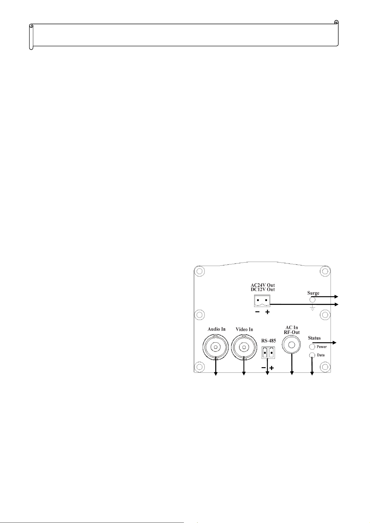
1.) Audio in (BNC connector): To connect audio
signal input.
2.) Video in (BNC connector): To connect video
signal input.
3.) Terminal blocks: To connect with PTZ camera;
the electrodes of the “+” & “-“ need to be matched
correctly with the electrodes of the PTZ camera
(e.g. + to (+) RS485/422 and - to (-) RS485/422).
4.) RF out/ AC in (F connector): Provide video/
audio /data signal output and AC power input.
5.) LED Data indicator: To indicate the status video and
RS-485/422. The status of LED is -- LED on: Normal, LED flash: Transmission error
6.) Surge protector: Connect to the earth-ground by shorter than 10 feet 16AWG or thicker cable.
1 2 3 4 5
6
7
8
7.) Power output: CTX-104VAD/AC provides AC 24V/2A (DC24V/2A Optional); CTX-104VAD/DC
provides DC12V/4A power output.
8.) LED Power indicator: To indicate the status power-on or power-off of CTX-104PVAD.
The status of LED is --- LED on: Normal, LED flash: Power not enough, LED Off: No power.
1
Page 2
3
4
5
6
7
--CRX-104PVAD--
1
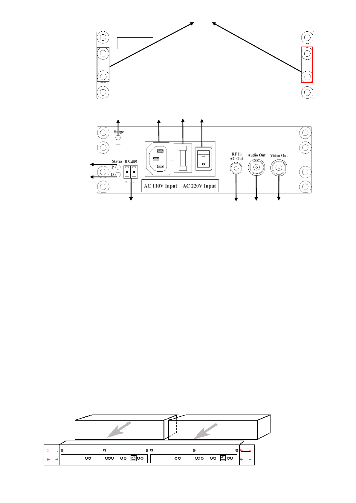
1.) Front panel screws: These screws are for fixing front panel and RPM-319 (19” rack mounting panel).
2.) LED Power indicator: To indicate the status power-on or power-off of CRX-104PVAD. The status of
3.) LED Data indicator: To indicate the status video and RS-485/422. The status of LED is --- LED on:
4.) Terminal blocks: To connect PTZ controller; the electrodes of the “+” and “-“ need to be matched
Back Panel
2
LED is --- LED on: Normal, LED flash: Power is not enough, LED Off: No power.
Normal, LED flash: Transmission error.
8 9 10 11
correctly with the electrodes of the PTZ controller (e.g. + to (+) RS485/422 and - to (-) RS485/422).
5.) RF in/ AC out (F connector): Provide video/audio/data signal input and AC80V power output.
6.) Audio out (BNC connector): To transmit output audio signal to DVR or Monitor.
7.) Video out (BNC connector): To transmit the output video signal to DVR or Monitor.
8.) Surge protector: Connect to the earth-ground by shorter than 10 feet 16AWG or thicker cable.
9.) Power plug: AC 100V-110V or AC 220V-240V power input.
10.) Fuse plug: To protect the device when power is short or overloading.
11.) Power switcher: To turn on /off power.
19” Rack Mount installation
Rack mounting (RMP-319, 19” rack mount panel) for three of CRX-104PVAD models
CRX-104PVAD
RMP-319
2
Page 3

Specification
10%
Item\Model CRX-104PVAD CTX-104PVAD/DC CTX-104PVAD/AC
Signal
Communication Type
Transmission Distance
Impedance
Video / Audio
RS-485
Input Power
Output Power
Surge Protection
Indicator
Environmental
Dimension (L x W x H)
Weight
Power/Video/Audio/Data
RF Modulation / RF Demodulation
Output Level: 110dBm; up to 1 Km (Using RG-11 coaxial cable)
F connector: 75 Ohm; BNC connector: 75 Ohm
Video: 1 Vp-p 75 Ohm; Audio: 3 Vp-p, 100K (Max.)
Simplex transmission; Baud rate: 2400-38400 bps
AC 110V / 220V ±
AC80V DC 12V/4A AC24V/2A or
DC Breakdown Voltage: 350V ± 15% (@ rising voltage 100V/s)
Impulse Breakdown Voltage: ≦ 700V (@ rising voltage 1KV/μs)
Insulation Resistance: ≧ 10000MΩ
Red: Power indicator Green: Video/Data indicator
Temperature: -10 ℃~60℃; Humidity: 0~95 % (Non-Condensing)
230 x 145 x 44 mm
2.6Kg 0.85 Kg
AC50V-80V AC50V-80V
DC24V/2A (Optional)
160 x100 x 65 mm
Transmission distance vs. Cable impedance & Cable attenuation
The formula below shows interactive factors between current and transmission distance. You are able to
calculate the power transmission distance when it is applied to the physical installation site.
I xΩΩΩΩx L < 40 (For AC power Speed Dome); i.e. The value of I xΩΩΩΩx L must be less than 40.
I xΩΩΩΩx L < 80 (For DC power Speed Dome); i.e. The value of I xΩΩΩΩx L must be less than 80.
I= Ampere (Speed dome requests current)
ΩΩΩΩ=Ohm per meter (Maximum DC loop resistance of coaxial cable )
L= Power transmission distance
The formula below shows video transmission distance. You are able to calculate the video transmission
distance when it is applied to the physical installation site.
A x L < 30; i.e. the value of A x L must be less than 30.
A = Attenuation per meter of coaxial cable @ 60M Hz frequency.
L= Video transmission distance
Product Application Diagram
3
Page 4

Installation Notes:
Please verify if joystick controller and PTZ camera (e.g. speed dome) if both of
ot
of the
RoSH
1. Please use point-to-point coaxial cable, RG-6 (5C) or RG-11 (7C) or better.
2. Please measure the wire resistance, use lower resistance coaxial cable to get better performance.
3. Please measure the wire attenuation, use lower attenuation coaxial cable to get better performance.
4. Make sure the power consumption / voltage of PTZ camera before installing the transmission system.
5. Please connect the shorter than 10 feet 16AWG or thicker cable between the CRX-104PVAD and
earth-ground; CTX-104PVAD and earth-ground for Surge protection.
6. Please turn off the power before you plug the coaxial cable on both CRX-104PVAD and
CTX-104PVAD Device.
7. To reduce a risk of fire or electrical shock, DO NOT exposes this product to rain area.
Troubleshooting:
Events Problem verification and solution
Can not power on
CRX-104PVAD power
indicator is light on, but
the CTX-104PVAD is not
power on
Faint or blurry picture
No video
1. Verify the power voltage if it matches for the CRX-104PVAD.
2. Verify the connected power source if it works fine and turn on.
1. Please verify if the using wire is RG-6 coaxial cable or better and if it is
connected to device correctly.
2. Please check end-to-end connectivity if the wire resistance is over device
specification.
1. Please verify if the coaxial cable wire is oxidized.
2. The power consumption of the camera is too high and over the system’
specification. Verify the power consumption of the camera from the vendor.
3. When the loading current is higher than expected, the power supply cannot
provide enough current for the system. Verify the power consumption of the
system including the camera and cable loss.
4. Poor connection at a punch-block.
1. Please check if all devices are powered on.
2. Please test periphery connected device (e.g. camera, monitor and wire)
separately to verify if it is working fine.
3. Please verify the port connector is correctly plugged in.
Joystick can not control
the PTZ cameras (e.g.
Speed dome camera)
1. Please verify if the data wire connecting properly.
2.
them can work fine.
3. When the wiring distance is longer than expected, the power supply cannot
provide enough voltage or current to the device. Measure the exact on-site
voltage of the PTZ camera with a voltage meter.
4. When the loading current is higher than expected, the power supply cann
provide enough current for the system. Verify the power consumption
system including all cameras and cable loss.
Customer Support:
Tel: 886-3-5103001 Email: support@i-view.com.tw
4
 Loading...