

Page 1
CP-4800DX XP DVR Board Hardware Manual (V1.0)
1
2
3
4
5
6
7
9
10
11
13
14
15
16
8
12
This section details the installation of CP-4800DX Pro DVR board and how to make the necessary connections.
You may install up to 2 cards into a PC to reach 32 Video and 32 Audio input. The primary one is referred as
CP-4800DX XP 0, the other one will be called CP-4800DX XP 1. Before you start, please make sure that your
PC is off, and the power cable is unplugged.
The DVR system is called CP-9600DX when combine the CP-4800DX XP 0 and XP 1 card onto a
PC together.
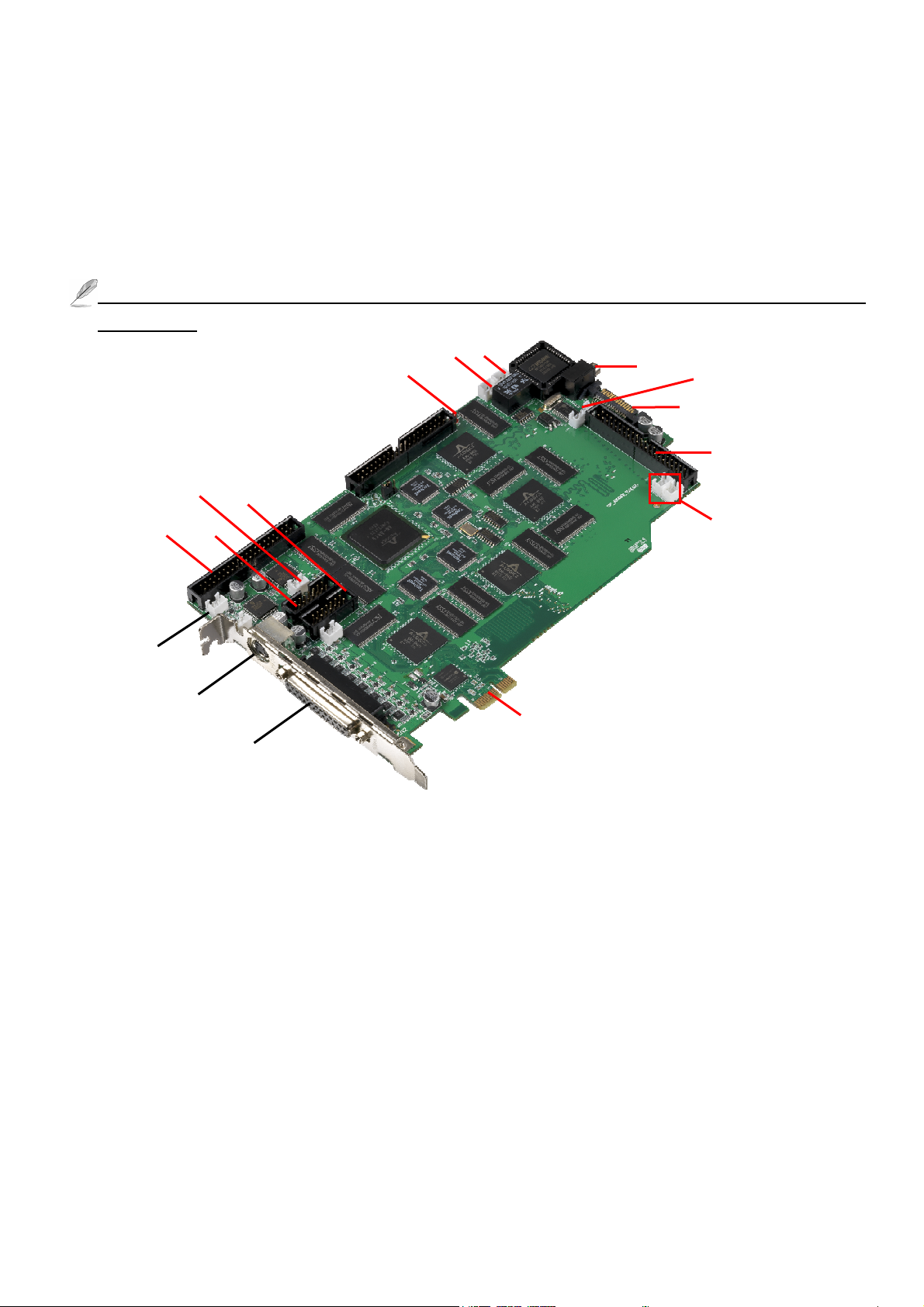
(Fig 1)
1
The description of CP-4800DX Pro (as Fig 1) pins and sockets:
1: Video input –DB25 pin to connect the D-Sub BNC cable for video input.
2: TV out – RCA connector provide split video output signal.
3&6: Transmit split video signal – Link the (3) socket of CP-4800DX XP 1 into the (6) socket of CP-4800DX
XP 0 DVR board to get 1-16 or 17-32 split video output via RCA Connector (2). (Optional)
4: Video looping- Connect to a video looping board for video loop-out.
5&7: Combine Spilt video signal – Link the (5) socket of CP-4800DX XP 0 into the (7) socket of CP-4800DX
XP 1 DVR board to get 32 split video output via RCA port. (Optional)
8: LED – The indicator of auto reboots function. (CP-4800DX XP 0 only)
9: RESET- System failure socket, connect to the “ Reset “ socket of PC Motherboard. (CP-4800DX XP 0)
10: EM_B – Panic button socket for emergency call. (CP-4800DX XP 0 only)
11: Sensor connector-Connect to the sensor cable of the remote controller. (CP-4800DX XP 0 only)
12: J_USB – Connect to USB cable to the USB port of PC Motherboard.
13: Power connector – Plug power in put from power supply of the PC to provide the power for the DVR card.
1
Page 2
14: Audio in - Connect to an audio board for 16 audio input. (Optional)
(Fig 2) (Fig 3) (Fig 5)
1
15: Sensor Signal– Connect the Card 0 and 1 via both ports to control split video out via a Remote Controller.
16: PCI Express Bus – Plug PCI Express slot of Motherboard.
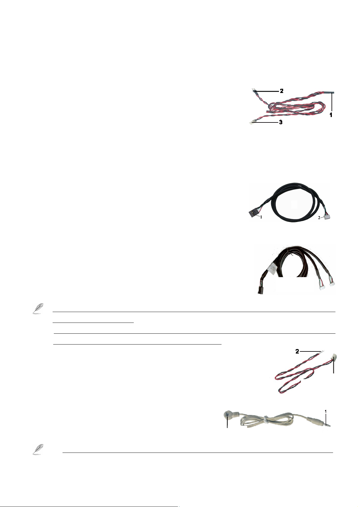
(A) System Failure Connections cable as shown in “Fig 2”:
The DVR system will reboot and restore to the original status
automatically when system crush occurs. Please follow the steps below to
connect these cables properly:
Connect the “3” connector of the “Fig 2” cable to the RST socket of DVR board.
Connect the “1” connector of the “Fig 2” cable to the Motherboard reset pin.
Connect the “2” connector of the “Fig 2” cable to the PC’s reset switch properly to complete.
(B) USB linking cable as shown in “Fig 3”:
Please follow the below steps to connect the USB cable to the CP-4800DX
Pro DVR Board and motherboard properly.
Plug the number “2 “connector of the “Fig 3” cable into the J_USB
socket (12) of each CP-4800DX Pro Board
Connect the number “1 “connector of the “Fig 3” cable to the USB
port of the motherboard.
The pins assignment of the “Fig 3” cable is:
Red: Vcc 5V White: Data- Green: Data+ Black: Ground
There is a two ports internal USB cables (refer to Fig 3.1) on the package
of CP-4800DX XP 1 DVR Board. You can use Fig 3.1 USB cable to
connect 2 pcs DVR board into internal USB port of PC when the PC
Motherboard does not have enough internal USB port.
1. The USB cable must be connected between DVR board and Motherboard; otherwise you cannot run the
Witness Pro program properly.
2. You can request the external USB cable from your supply to connect the USB port of PC when the
Motherboard does not have enough internal USB port. (Option)
(C) Panic Button as shown in “Fig 4”:
Connect the number “1” connector to the 11 (EM_B) of the CP-4800DX XP 0
DVR Board.
And then connect the number “2” connector to the panic button for
emergency call.
(D) Sensor cable as shown in “Fig 5”
(Fig 3-1)
Fig 4
To install the sensor, simply plug the end of the sensor device
(“1” connector of the “Fig 5 ”) into the Sensor connector of
Sensor
CP-4800DX XP 0 DVR Board.
1. Please shut down the power of PC when you plug in the sensor cable into the DVR board, otherwise
2
Page 3

2
it will cause the sensor damage.
(Fig 8) 1 2
(Fig 7)
(Fig 9)
2. Make sure that the sensor itself is not covered and is facing the place from where you will be using the
remote controller.
3. Make sure that the sensor itself plug into the phone jack completely.
4. The system allows to extent sensor cable (Fig 5) for control the TV out from far away site via Remote
Controller. Please follow the process as below to achieve this function:
a. Please use the shading cable such as 28#2C+S type.
b. The sensor cable includes 3-wire cable: Red (DC 5V), Shading cable (Ground), White (Signal).
c. If the extension sensor cable too far away DVR and needs extra DC5 V power for the sensor,
(E) Power Cable (Fig 6)
Plugged “ 1 “ port to the power supply of PC, the other “2” or “3 “ ends should be
connected to CP-4800DX.
1. Must provide the power for the CP-4800DX Pro, otherwise cannot work
properly.
2. Do not share power for the other devices for each power line when connected CP-4800DX.
(F) Linking cable (Fig 7) CP-4800DX XP 1 only
The Linking cable on the package CP-4800DX XP 1 to connect the port between the (3) port of CP-4800DX
XP 0 and (6) port of CP-4800DX XP 1.
(G) Audio Board (Optional) as shown in “Fig 8 ”
Connector the “1 “of the Fig 8 with a DB-25 pins audio connector
3
1
(Fig 6)
(as shown in Fig 10) for the audio inputs.
Plug the “2” of the Fig 8 into the “14” Audio-in socket of the DVR card.
(H) Audio Cable (Option) as shown in “Fig 9”.
Connect the DB-25 Pin connector to the Audio Board (As Fig 9).
Connect the 16 BNC audio connectors for the audio inputs.
The mark “A” on the BNC connector’s means “ Audio input”.
The mark “A1” on the BNC video connector means “Audio 1”,
“A2” means “Audio 2” etc.
(I) Video Looping Board and cable (Optional) as shown in “Fig 10 ”
Using flat cable to connect the video looping board and CP-4800DX DVR card.
Plug DP-25 pin BNC cable to Video looping board
Connector the “1 “of the Fig 10 with a DB-25 pins audio connector
The BNC connector will provide 16 video output signal.
The mark “V” on the BNC connector’s means is the mark “V1” on
DB-25 Pin
BNC Audio
Connectors
Fig 10
the BNC video connector means “Video1”, “V2” means “Video 2”…
3
Page 4

1. Completing Setup
Complete setup by following three steps:
1. Run Witness XP program, login, and press the System configuration button. In the system
configuration window, enable both “Watch dog timer” and “Auto-run”.
2. Disable the Windows login password; let your PC proceeds directly into Windows, otherwise the system can
not work properly when Power Failure or System Failure reboot, because of the halt by the login Windows.
3. After everything is connected and the prior two steps are completed, turn on your PC, run Witness Pro and
make sure that CP-4800DX XP 0’s LED display the following behavior: Light is on for 20 seconds, then off
for 20 seconds, then on for 20 seconds, etc to confirm that the system is working properly.
2. Using the Remote controller
On your remote controller, there should be buttons labeled with numbers representing camera numbers. Points
the remote controller at the sensor/receiver, press the number of the camera you wish you to on the TV and it
would appear.
Number key: For the video channels selections.
Simply press the number key from the “Display”
section to display the selected video channel on the
connected monitor.
F1: Click this key to select the 1-16 split video out of CP-4800DX XP 0 Card (Main Monitor 0).
F3: Click this key to select the 17-32 split video out of CP-4800DX XP 1 Card (Main Monitor 1).
F2: Click this key to select the 1-16 split video out of Spot Monitor 0 (Option)
F4: Click this key to select the 17-32 split video out of Spot Monitor 1 (Option).
Split Section: Push the splitter key on “ Split ” section, and then you will watch the splitter video on TV.
(Click the ● icon to change 6, 8, 10, 13 split screen sequence)
Return: After you use Display function, then you will return to all channels scroll. You need to push F1, F2,
F3 or F4 and then “ Return “ key to go back the TV display when you click the “ Return “ Key.
For example:
1. If you want to view the video of camera 22 on TV; click “ F3 “ key and then entry “ 6 “ number key, you
will watch the camera 22 single video on TV.
2. If you want to view the 4 split video (Camera 17-20) on TV; click “ F3 “ key and then entry “
you will watch the 4 split video (Camera 17-20) on TV.
The “ 1-16 “ number key of Display section, “ 1 “ number represent camera 1 and 17, “2” represent camera 2 and
“key, then
18.
4
 Loading...