

Page 1
4
ATX-100V/ARX-100V/ARX-400V Installation Guide
Product Overview:
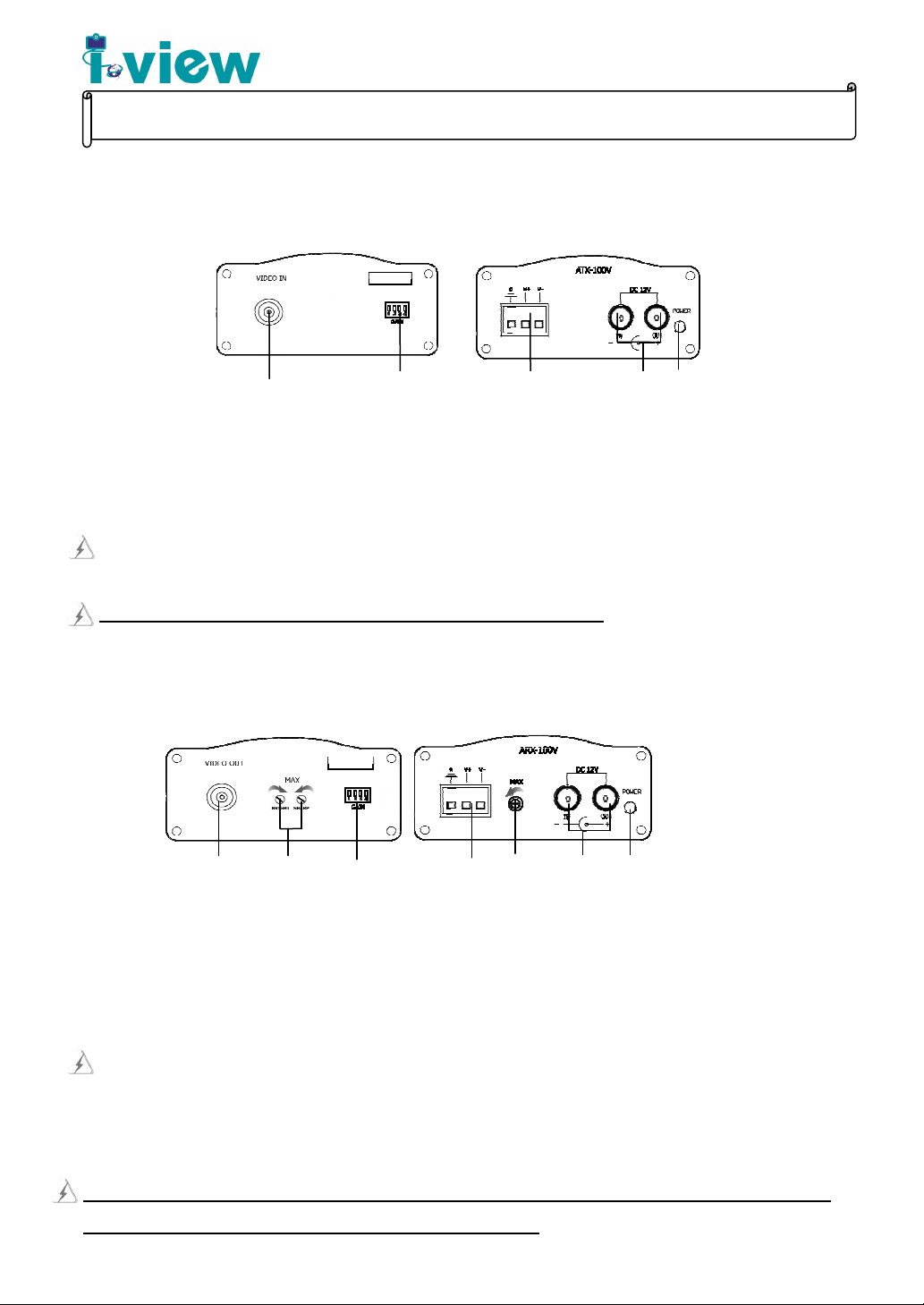
ATX-100V Function Description:
1.) BNC ports: To connect with camera device for input video signal.
2.) Gain dip switch: According to the cable category and distance, user may need to adjust this switch to get optimum video picture.
3.) Terminal blocks: The terminal blocks V+ (& V-) ports of ATX-100V need to connect and match with remote V+ (& V-) of
ARX-400V / ARX-100V by UTP wire of category 2 to 5 or better.
As for “S “ surge suppression port connects to earth-ground by shorter than 10 feet 16AWG or thicker cable.
4.) Power jack: Input and output DC12V power supply for itself and another device (e.g. camera).
Total current cannot over power consumption of ATX-100V and connecting device.
1 2 3
Rear Panel Front Panel
5
V1.7
5.) Power indicator: To indicate ATX-100V’s power status.
ARX-100V Function Description:
1.) BNC ports: To connect with BNC connector of monitor or DVR.
2.) Bright/Sharp adjusters: To adjust video’s quality with a monitor for remote camera’s video signal.
3.) Gain dip switch: According to the cable category and distance, user may need to adjust this switch to get optimum video picture.
4.) Terminal blocks: The terminal blocks V+ (& V-) ports of ARX-100V need to connect and match with remote V+ (& V-) of
ATX-100V or V- (& V+) of PTT-130V (S) / PTT-120V by UTP wire of category 2 to 5 or better.
As for “S “ surge suppression port connects to earth-ground by shorter than 10 feet 16AWG or thicker cable.
5.) Impedance adjuster: To increase and restore original video signal.
6.) Power jack: Input and output DC12V power supply for itself and another device (e.g. camera).
7.) Power Indicator: The Green LED for indicates ARX-100V’s power status.
Front
1 2
3 4
Rear
5
6 7
The terminal blocks or RJ-45 V+ (V-) of ARX-100V & ARX-400V (at DVR site) need to connect and match with V- (V+) of
PTT-120V / PTT-100VP / PTT-130V(S) connecting devices (at camera site).
Page 2
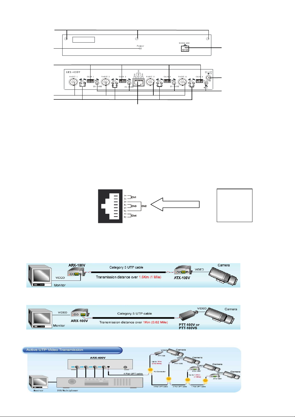
ARX-400V Function Description:
1.) Surge ground: As for “S “ surge suppression port connects to earth-ground by shorter than 10 feet 16AWG or thicker cable.
2.) Front panel screws: The screws for fixing front panel and RMP-219 (19” rack mount panel)
3.) Power indicator: To indicate the status power-on or power-off of ARX-400V.
4.) Gain dip switches: According to the cable category and distance, user may need to adjust this switch to get optimum video picture.
5.) BNC ports: To connect with BNC connector of monitor or DVR.
6.) Bright/Sharp adjusters: To adjust video’s quality with a monitor for remote camera’s video signal.
7.) 8 pin RJ-45 connector: To connect to ATX-100V or PTT-100V(S) /130V(S) /120V by UTP wire of category 2 to 5 or better. Refer
2
3
4
5
6
to the pin assignment as below:
ARX-400V/100V RJ45
Front Panel
Rear Panel
7
UTP cable
1
9
8
Remote Terminal
ATX-100V
8.) Impedance adjuster: To increase and restore original video signal.
9.) Power jack: Plug DC12V power supply.
Video
or PTT-120V
or PTT-130V
Product Application Diagram and Installations
Using the ARX-100V to connect with ATX-100V at both Monitor and camera ends.
Using the ARX-100V to connect with PTT-100V(S) /130V(S)/120V at both Monitor and camera ends.
Using the ARX-400V to connect with PTT-100V/130V(S)/120V and ATX-100V devices at both DVR control and cameras ends
Page 3

RMP-219
Rack Mounting (RMP-219, 19” rack mount panel) for two of ARX-400V model.
Pin assignment of ARX-400V/100V RJ45 connector: Please use UTP wire of category 2, 3, 4, 5 or better to connect with the
terminal blocks of remote PTT-100V(S)/PTT-130V(S)/PTT-120V or ATX-100V.
Video signal adjusters: Gain Value dip switch ( ), Impedance adjuster ( ) and Bright/Sharp adjuster ( )
User may need to use the video signal adjusters to make clear picture on monitor. To restore original clear picture for long distance
wiring connection, please follow the steps below:
Step1: If use ATX-100V to connect with ARX-100V/ARX-400V, please adjust the ATX-100V’s “Gain Value dip switch” first
according to the distance of connecting UTP wire. The table below shows the relationship of transmission distance and dipswitch.
ARX-400V/100V RJ45
Device1 Device2
UTP cable
Video
Remote Terminal
ATX-100V or PTT-100V
PTT-120V or PTT-130V
Wire distance
Dip switch
Step2: Adjust the Gain Value dipswitch of ARX-100V/ARX-400V: Please switch each level (from level 1 to 7) from the table below
until an optimum video quality shows on monitor. (Level 1 = Lowest gain; Level 7 = Highest gain)
Levels
Dipswitch
Step3: Please use mini screwdriver to adjust the Bright from ( ) to make picture bright enough then adjust the Sharp to
make picture more clear. Repeat Step 2 and 3 to get the optimum video quality.
Step4: If the picture still bur or unclear to see, please use mini screwdriver to adjust the Impedance adjuster ( ).
1. For over 1Km end-to-end transmission distance, the camera site uses the ATX-100V for long distance video signal
transmission.
2. Please note the level of dip switch will be subjected to change by different types of UTP cable
300M ~ 600M 600M ~ 1000M 1000M ~ 1600M
1 2 3 4 5 6 7
Installation Notes:
1. Please use point-to-point Unshielded Twisted Pair wire, 24-16 AWG, Category 2 or better.
2. Please ensure the connected power source is connected to earth ground during normal use.
3. To reduce a risk of fire or electrical shock, DO NOT expose this product to rain or moisture area.
4. Please DO NOT USE SHIELD TWISTED PAIR WIRE.
5. Please do not have “bridge-taps” or loading coils in installation, and NOT put the device in high-voltage wiring.
Page 4

Troubleshooting:
Events Problem verification and solution
Can not power on
Ghosts, faint shadows
Faint or blurry
picture
No video
1. Please test with other device to verify that the AC outlet or power source (e.g. UPS) is supplying power
and the voltage is between AC100V to AC240V (50Hz / 60Hz)
2. Please verify that the power adapter is connected properly and with a good solid grounding.
3. Please verify the connected power source is working fine and power on.
1. Please verify that the using wire is “Un-shield Twister Pair” wire, and is connected properly.
2. Please check if there is a “bridge tape” in the installation and remove it.
3. Please verify that if the ground wire is connected properly.
4. Please check if there is a crosstalk in the installation.
1. Please verify that the using wire is “Un-shield Twister Pair”, and is connected properly.
2. Please verify if the Un-shield Twister Pair is oxidized. If so, please replace a new one.
3. Please verify end-to-end connectivity with an ohmmeter to check if the wire distance is over expected
(1.6Km for ARX-100V/ARX-400V connecting to ATX100V, 1Km for ARX-100V/ARX-400V
connecting to PTT-100V/130V (S)/120V. The testing result base on the Category 5 UTP cable and color
camera.)
4. Please follow the “Video signal adjusters” to adjust the “Gain value dip switch”, “Impedance adjuster”
and “Bright/Sharp adjuster.
1. Please check if all devices are power on.
2. Please test periphery connected device (e.g. camera, monitor and wire) separately to verify if it is
working fine.
Specification:
Model/ Item ARX-400V ARX-100V ATX-100V
Communication Type
Port Number
Transmission Signal
Connector
Impedance
Wire Cable
Surge Suppression/ RF Noise Immunity /
Cross Talk Immunity/ Distance Equalization
Power request
Environmental
Dimension (W x H x L ) / Weight
Customer Support:
Receiver Transmitter
4 1
Video
BNC, & RJ 45 BNC & Screw Terminal
BNC: 75Ω; Terminal Block: 100 Ω
Category 2 or better; Unshielded Twisted Pair 24-16 AWG (0.5-1.31mm)
Yes
DC12V/300mA DC12V/100mA
Temperature: 0-50℃ Humidity: 0 to 95% (non-condensing)
215 x 55x 35 mm / 0.5Kg
97 x 60 x 35 mm / 0.2Kg
Tel: 886-3-5103001 Fax: 886-3-5103002
Email: support@i-view.com.tw
 Loading...