

Page 1
1
Page 2

Table of Contents
About This Guide ------------------------------------------------------------------------------------------------- 4
FCC Compliance Statement ------------------------------------------------------------------------------------ 4
FCC Warning ------------------------------------------------------------------------------------------------------ 4
License Agreement ------------------------------------------------------------------------------------------------ 5
Trademark ---------------------------------------------------------------------------------------------------------- 7
Customer Support ------------------------------------------------------------------------------------------------ 7
Chapter 1 Product Introduction ------------------------------------------------------------------------------- 8
1-1. Model Description ------------------------------------------------------------------------------- 8
1-2. Product Package Content ----------------------------------------------------------------------- 8
1-3. Recommend HDD List ------------------------------------------------------------------------- 9
1-4. Product Overview ----------------------------------------------------------------------------- 10
Chapter 2. Hardware Installation ---------------------------------------------------------------------------- 12
2-1. How to Build up the Raid HDD ------------------------------------------------------------- 13
Chapter 3. NVR Operating System -------------------------------------------------------------------------- 16
3-1. NVR System Control Panel Configuration ------------------------------------------------ 17
3-2. NVR Main Program -------------------------------------------------------------------------- 20
3-3. Program Overview ---------------------------------------------------------------------------- 21
Chapter 4. NVR Software Operation ------------------------------------------------------------------------ 29
4-1. Surveillance Server (Witness Pro) ---------------------------------------------------------- 29
4-2. Logging in the Surveillance Server --------------------------------------------------------- 36
4-3. Camera configuration ------------------------------------------------------------------------- 37
4-4. Video playback / Synchronized playback / Text insert playback / ezBack ----------- 55
4-5. Remote Access setup -------------------------------------------------------------------------- 71
4-6. System Configuration /Video display configuration/Connection ezDispatch Server setup/
Save/Load configuration / 2-Way audio setup / Remote Control setup --------------------- 77
4-7. User access setup ------------------------------------------------------------------------------ 85
4-8. Application logs ------------------------------------------------------------------------------- 89
4-9. Peripherals setup ------------------------------------------------------------------------------- 91
4-10.
Stop alarm siren ------------------------------------------------------------------------ 95
2
Page 3

4-11.
4-12.
4-13.
Chapter 5. Accessory Programs ------------------------------------------------------------------------------ 111
5-1. ezRServer - Remote Control Server ------------------------------------------------------- 115
5-2. ezSTalk - Two-way voice Communication --------------------------------------------- 118
5-3. ezReboot - Auto-restart the NVR machine ----------------------------------------------- 120
5-4. ezClock - Auto-synchronized time --------------------------------------------------------- 121
5-5. ezHDDSmart - HDD Health Checkup ---------------------------------------------------- 122
5-6. ezUPSCheck ---------------------------------------------------------------------------------- 125
5-7. ezMobileServer – MobileView Server ---------------------------------------------------- 126
5-8. Other Applications --------------------------------------------------------------------------- 127
Chapter 6. Remote Client PC Software ------------------------------------------------------------------- 132
6-1. Start Using FreeView Pro (Remote Client Program) ----------------------------------- 132
6-2. Remote Client Program Operation--------------------------------------------------------- 133
Chapter 7. Mobile device remote viewing Software ---------------------------------------------------- 165
7-1. PDAView & MobileView program installation ------------------------------------------ 165
7-2. PDAView & MobileView Application ---------------------------------------------------- 166
7-3. ezMobileServer Application ---------------------------------------------------------------- 167
Storage configuration ------------------------------------------------------------------ 95
Public address configuration -------------------------------------------------------- 100
Control Panel -------------------------------------------------------------------------- 106
3
Page 4

About This Guide
Conventions used in this guide to make sure that you perform certain tasks properly, take note of the following
symbols to use throughout this manual.
WARNING: Information to prevent injury to yourself when trying to complete a task.
CAUTION: Information to prevent damage to the components when trying to complete a task.
IMPORTANT: Information that you must follow to complete a task.
NOTE: Tips and additional information to aid in completing a task.
FCC Compliance Statement
This device complies with part 15 of the FCC Rules. Operation is subject to the following two conditions:
This device may not cause harmful interference, and this device must accept any interference received,
including interference that may cause undesired operation.
FCC Warning
This equipment has been tested and found to comply with the limits for a Class B digital device, pursuant to
Part 15 of the FCC Rules. These limits are designed to provide reasonable protection against harmful
interference in a residential installation. This equipment generates uses and can radiate radio frequency
energy and, if not installed and used in accordance with the instructions, may cause harmful interference to
radio communications. However, there is no guarantee that interference will not occur in a particular
installation. If this equipment does cause harmful interference to radio or television reception, which can be
determined by turning the equipment off and on, the user is encouraged to try to correct the interference by
one or more of the following measures:
Reorient or relocate the receiving antenna.
Increase the separation between the equipment and receiver.
Connect the equipment into an outlet on a circuit different from that to which the receiver is connected.
Consult the dealer or an experienced radio/TV technician for help.
Shielded cables and I/O cords must be used for this equipment to comply with relevant FCC regulations.
4
Page 5

License Agreement
Notice to end-user: please read the following legal agreement carefully. Use of the Witness or any of the
software provided with this agreement constitutes your acceptance of these terms. If you do not agree with
the terms of this agreement, PROMPTLY RETURN the Witness system, Witness, AnyView Pro and
FreeView Pro , any related software and the included items (including the Witness video system, written
materials and containers) to the location where you purchased them for a full refund.
1-1. License Grant. I-View grants to you (either as an individual or an entity) a personal, nonexclusive,
nontransferable license to use one copy of the executable code of the I-View's Witness, FreeView Pro
and AnyView Pro on a single CPU residing on your premises. The term of this Agreement will be for the
duration of I-View’s copyright in the Witness, FreeView Pro and AnyView Pro. You may assign your
rights under this Agreement to a third party who agrees in writing to be bound by this Agreement prior to
the assignment, and provided that you transfer all copies of the Witness, FreeView Pro and AnyView Pro
and related documentation to the third party or destroy any copies not transferred. Except as set forth
above, you may not assign your rights under this Agreement, nor shall you rent, lease, sell, sublicense or
otherwise transfer the Witness, FreeView Pro and AnyView Pro.
1-2. Reverse Engineering. You may not reverse engineer, decompile or otherwise disassemble the Witness,
FreeView Pro and AnyView Pro except to the extent that applicable law expressly prohibits this
restriction.
1-3. Copyright. Title and full ownership rights to the I-View's Witness, FreeView Pro and AnyView Pro will
remain the exclusive property of I-View or its suppliers, and you will not acquire any rights to the
I-View's Witness, FreeView Pro and AnyView Pro except as expressly set forth above.
1-4. Maintenance. I-View is not obligated to provide maintenance or updates to you for the Witness
system and transport to Witness, FreeView Pro and AnyView Pro. However, any maintenance or updates
by I-View shall be covered by the Agreement.
1-5. Disclaimer of Warranty. I-View warrants that the Witness system, the witness FreeView Pro and
AnyView Pro and related software will perform substantially in accordance with the accompanying
documentation and those CD-ROM diskettes are free from any defects for a period of 90 days from the
date of purchase (limited warranty). Except for the foregoing limited warranty, I-View expressly
disclaims any and all other warranties, whether express or implied, including without limitation, the
implied warranties of merchantability, fitness for a particular purpose, and non-infringement of third
5
Page 6

party rights. If law does not permit such disclaimer of any implied warranty, the duration of any such
implied warranties is limited to 90 days from the date of purchase. Some countries do not allow the
disclaimer of implied warranties, limitations on how long an implied warranty lasts, or the exclusion or
limitation of incidental or consequential damages, so such limitation as or exclusions may not apply to
you. This warranty gives you specific legal rights and you may also have other rights, which vary, from
state to state.
1-6. Customer Remedies. In the event the Witness system or related software does not meet or conform to
the Limited Warranty, I-View’s entire liability and your sole and exclusive remedy shall be, at I-View's
option, either to (a) correct the error, (b) help you work around or avoid the error or (c) authorize a refund
so long as the Witness system documentation and CD-ROM diskettes are returned to I-View with a copy
of your receipt. This Limited Warranty is void if failure of the Witness system has resulted from accident,
abuse, or application. Any replacement Witness system will be warranted for the remainder of the
original warranty period.
1-7. No Liability for Consequential Damages. In no event shall its suppliers be liable to you for any
incidental, indirect, special or consequential damages of any kind rising out of or related to this
agreement or use or inability to use the related software, even if I-View has been advised of the
possibility of such damages.
1-8. Please acknowledge that the laws and regulations of the Taiwan R. O. C. restrict the export and
re-export of commodities and technical data of Taiwan R. O. C. origin. You may not download or
otherwise export or re-export the Witness system or related software or any underlying information or
technology except in full compliance with all United States and other applicable laws and regulations.
You agree to indemnify and hold I-View harmless from and against any and all liability arising from or
relating to your breach of this Manual.
1-9. Governing Law; attorneys' fees. The laws of the Taiwan R. O. C will govern this agreement. Without
regard to conflict of law principles. The R. O. C. Convention on Contracts for the International Sale of
Goods is specifically disclaimed. The prevailing party shall be entitled to recover its reasonable attorneys'
fees in the event of a dispute arising out of or relating to this Agreement.
1-10. Entire Agreement. This is the entire agreement between you and I-View with respect to the use of the
Witness, FreeView Pro and AnyView Pro, which supersedes any prior agreement, whether written, or
oral, and all other communications between the parties relating to the subject matter of this Agreement.
6
Page 7

Should you have any questions concerning this Agreement, please contact I-View directly at one of the
numbers or addresses listed at the beginning of this manual.
Trademark
DigiCap II, DSecu, AnyNet, e-Witness, AnyNetPro, u-Witness XP, x-Witness, FreeView Pro, AnyView Pro,
PDAView and MobileView are registered trademarks of I-View Communication Inc.
Microsoft, Windows 95, 98, ME, Windows2000, XP, Vista and 7 are registered trademarks of Microsoft
Corporation. All other trademarks are the property of their respective holders.
Customer Support
If technical problems arise with the use of our products in which you and your vendor cannot resolve, please
try the following: If you have an Internet connection, visit the I-View website http://www.i-view.com.tw
(Taiwan) for any software or product updates, or email to support@i-view.com.tw (Taiwan) or Tel:
886-3-510-3001 Fax: 886-3-510-3002 (Taiwan). We are dedicated to providing the highest quality support.
E-mailing our tech support will give you the chance to document each of the above items in a very clear and
concise manner and will give our support team a chance to document any problems and respond with
thoroughly researched answers.
7
Page 8

Chapter 1 Product Introduction
1-1. Model Description
Model Description
AnyNet-3208
AnyNet-6416
AnyNet-6424
32 channels I-View’s IP devices and/or 32 channels third-party IP devices digital
video recorder provide 8 hot-swap SATA drive bays up to 32 TB HDD capability
(4TB *8) with Raid 0, 1, 5, 10 functions.
Has option of redundancy Power supply and 4/6/8 monitors display.
64 channels I-View’s IP devices and/or 32 channels third-party IP devices digital
video recorder provide 8 hot-swap SATA drive bays up to 64 TB HDD capability
(4TB *8) with Raid 0, 1, 5, 6,10 functions.
Has option of redundancy Power supply and 4/6/8 monitors display.
64 channels I-View’s IP devices and/or 64 channels third-party IP devices digital
video recorder provide 8 hot-swap SATA drive bays up to 96 TB HDD capability
(4TB *8) with Raid 0, 1, 5, 6, 10 functions.
Has option of redundancy Power supply and 4/6/8 monitors display.
1-2. Product Package Content
Thank you for choosing the I-View Embedded NVR system. Before you start installing the
hardware devices with the NVR, please check the items of the product package with the list
below,
Recover DVD
User manual & Power cable
Screws for HDD installation
Mouse
If any of the above items is damaged or missing, contact your retailer.
8
Page 9

1-3. Recommend HDD List
Seagate
Model
ST3000VX000 3TB SATA 6 Gb/Sec.
ST2000VX000 2TB SATA 6 Gb/Sec.
ST1000VX000 1TB SATA 6 Gb/Sec.
Western Digital
Model
WD1001FALS 1TB SATA 3 Gb/Sec.
WD1002FBYS 1TB SATA 3 Gb/Sec.
WD2002FYPS 2TB SATA 3 Gb/Sec.
WD2003FYYS 2TB SATA 3 Gb/Sec.
WD30EZRS 3TB SATA 3 Gb/Sec.
1. The most 7200RMB SATAII/III HDD can capability with NVR. You can all your local dealer
before buy the HDD.
2. We recommend using the same model HDD on a system when you use the Raid 5 or 6.
3. You must use the same HDD size on a system when you use Raid 5 or 6.
9
Page 10
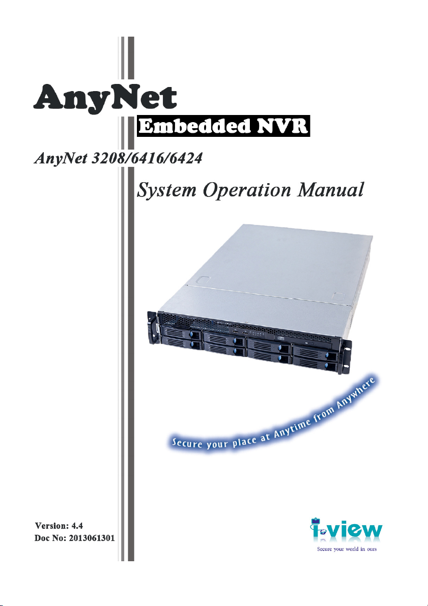
1-4. Product Overview
Front Panel of AnyNet Embedded NVR System
Anynet-3208/6416/6424 Rear Panel
AnyNet-3208
1 2 3 3 4 5 6 7 8 8 9 10
1. DVD drive
2. Remove Hot swap HDD
3. USB 3.0 ports
4. Power Switch
5. System reset button
6. Alarm Mute button (Revised);
7. System HDD Activity indicator LED
8. Power indicator LED
9. Failed indicator LED (Revised)
10. LAN1 & LAN 2 indicator LED (Revised)
AnyNet-3208
AnyNet-6424
10
Page 11
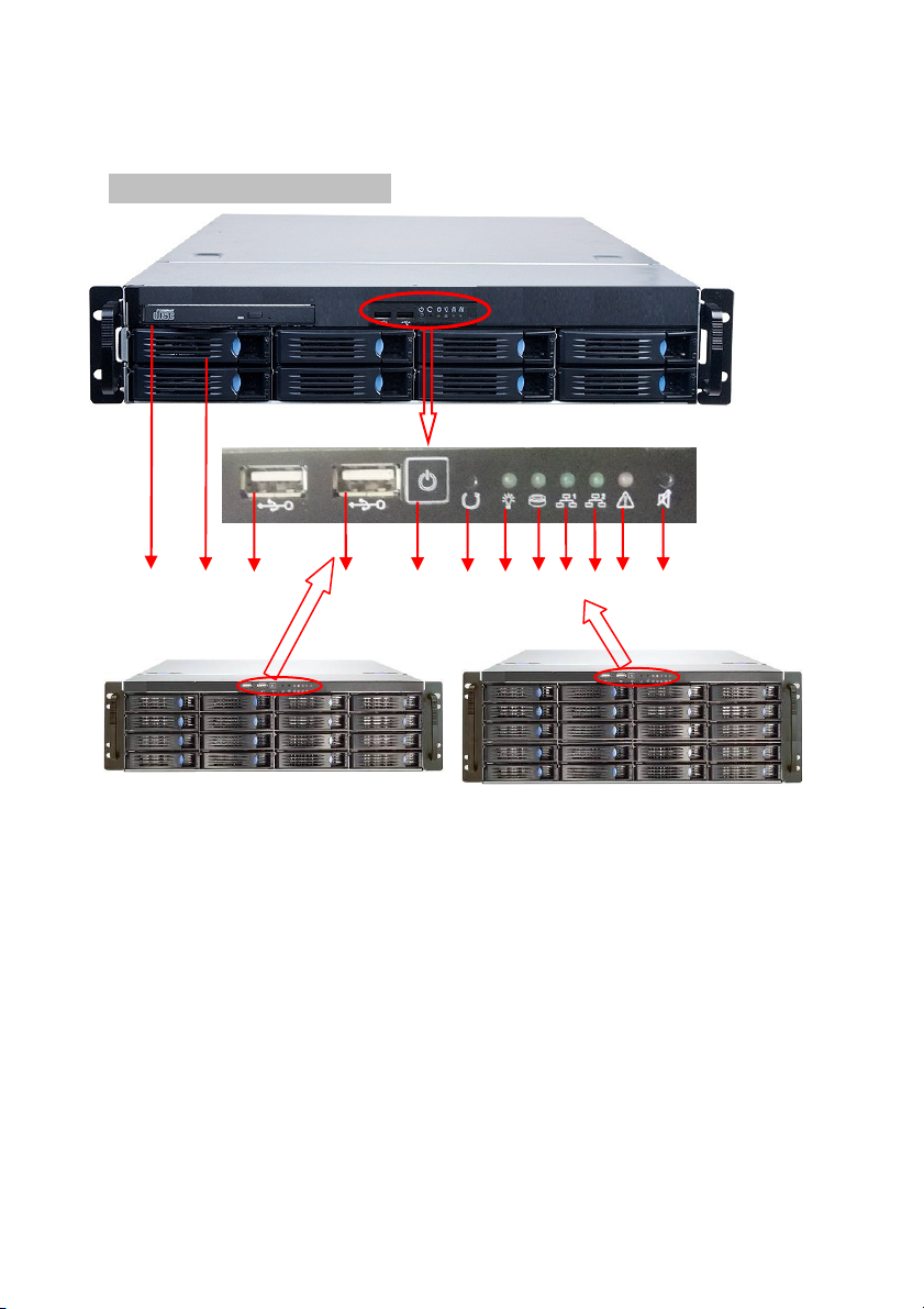
Anynet-3208/6416/6424 Back Panel
1. Power supply: The power supply can be selected optional redundancy power supply.
2. Supplied power cord: Connect one end to the AC input.
3. Power switch: Turn on/off power supply.
4. PS2 keyboard/ mouse combo port: This port is for a PS2 keyboard/mouse.
5. USB port: For USB device plug in.
6. HDMI port: This port for HDMI monitor.
7. S/PDIF port: Audio output port..
8. VGA port: 15-pins ports for VGA monitor or device.
9. DVI-DL port: Support DVI-D Signal output only.
10. e-SATA port: Plug e-SATA devices.
11. RJ-45 LAN port#1: Connect to Switching HUB. The default IP address is 192.168.1.1
12. USB port: For USB device plug in.
13. Line in (Blue): This port connects to CD, DVD audio source. Speaker out (Lime): This port
connects to speaker. Microphone in (Pink): This port connects to microphone,
14. RJ-45 LAN port#2: Connect to Switching HUB. The default IP address is 192.168.0.1
1 2 3 4 5 6 7 8 9 10 12 13 14
AnyNet-6416
11
AnyNet-3208
AnyNet-6424
11
Page 12
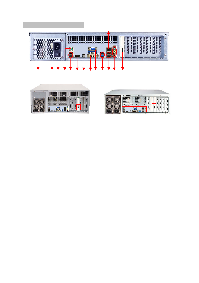
Chapter 2. Hardware Installation
Please use the HDD which supports 7200 RMP or above and the same model when you use
the Raid 5 or 6 mode.
Install Hard Disk Drive
①
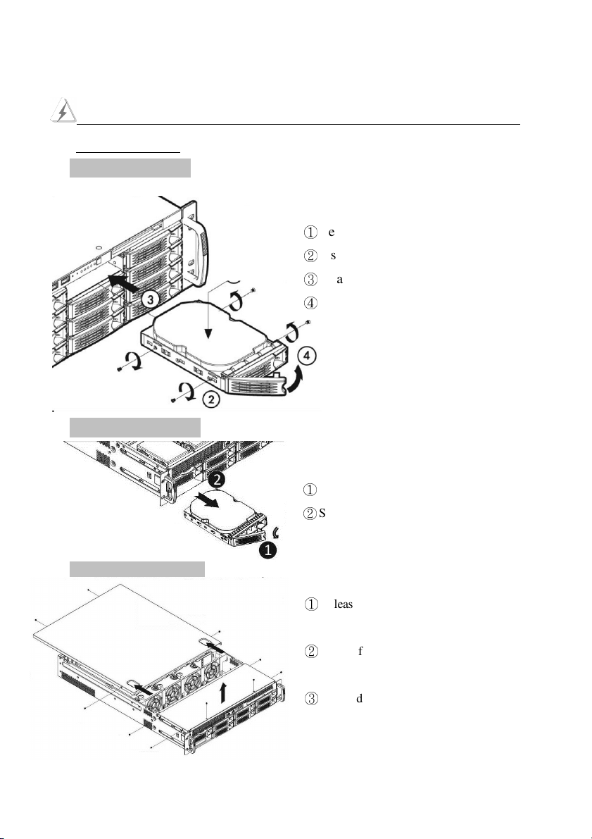
Remove Hard Disk Drive
Remove top cover of NVR
Remove protect tray from the tray.
②
Insert the HDD on the tray.
③
Attach with 4 screws to fix HDD.
④
Push the lever to latch HDD tray.
①
Pull the lever to latch HDD tray.
②
Slide tray from HDD tray.
①
Release two screws on the back side and twp
screws on both left and right side.
②
Thumb finger touch downward, and then push
back the rear back cover.
③
Put hand on the front top cover pull it out.
12
Page 13
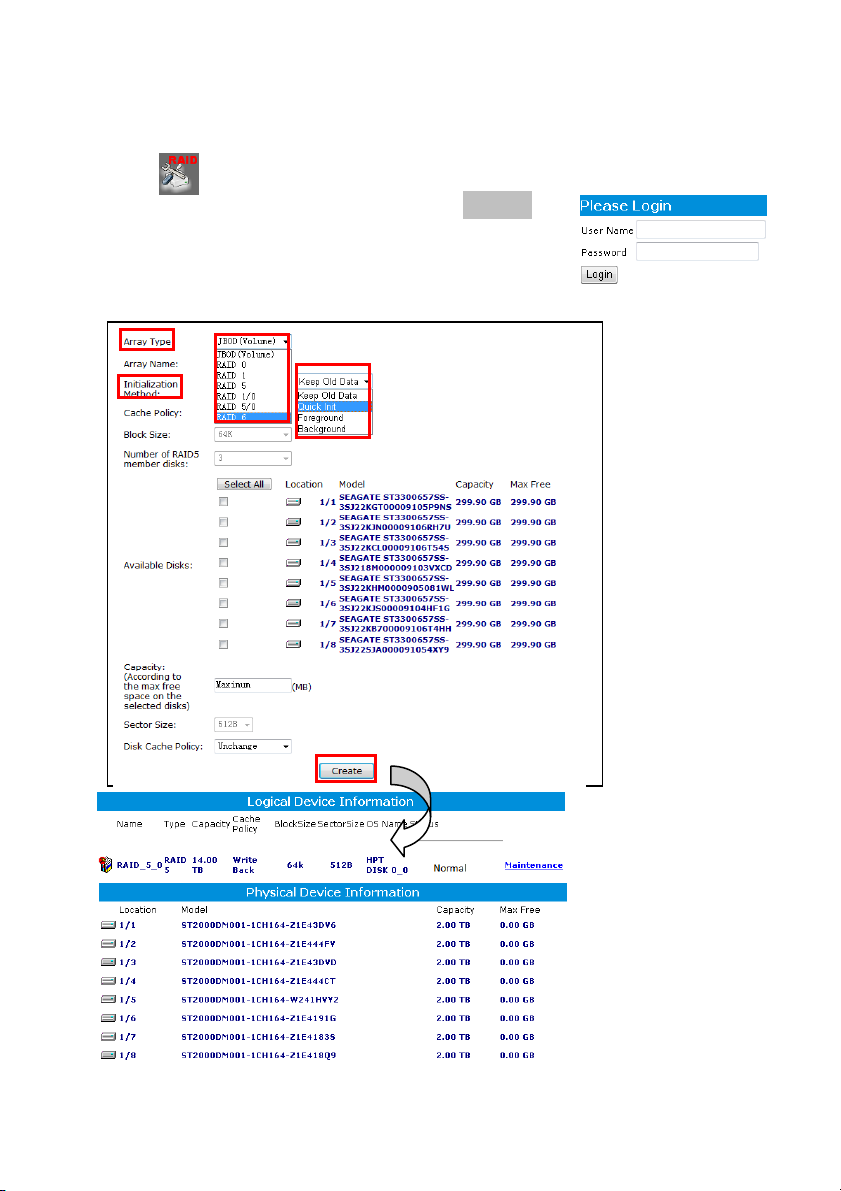
2-1. How to Build up the Raid HDD
To build up the new Raid HDD on the AnyNet NVR follow the steps shown as below:
Step 1. Click button from Control panel to enable the Raid setting diagram.
Step 2. Entry the User name and Password. The default is RAID/hpt.
Step 3. Click “ Array type” icon to select the mode and Click
“Quick Init” icon from Initialization Method section.
Step 4. Check HDDs which you want to create the Raid function, then click “ Create “ icon to start.
13
Page 14
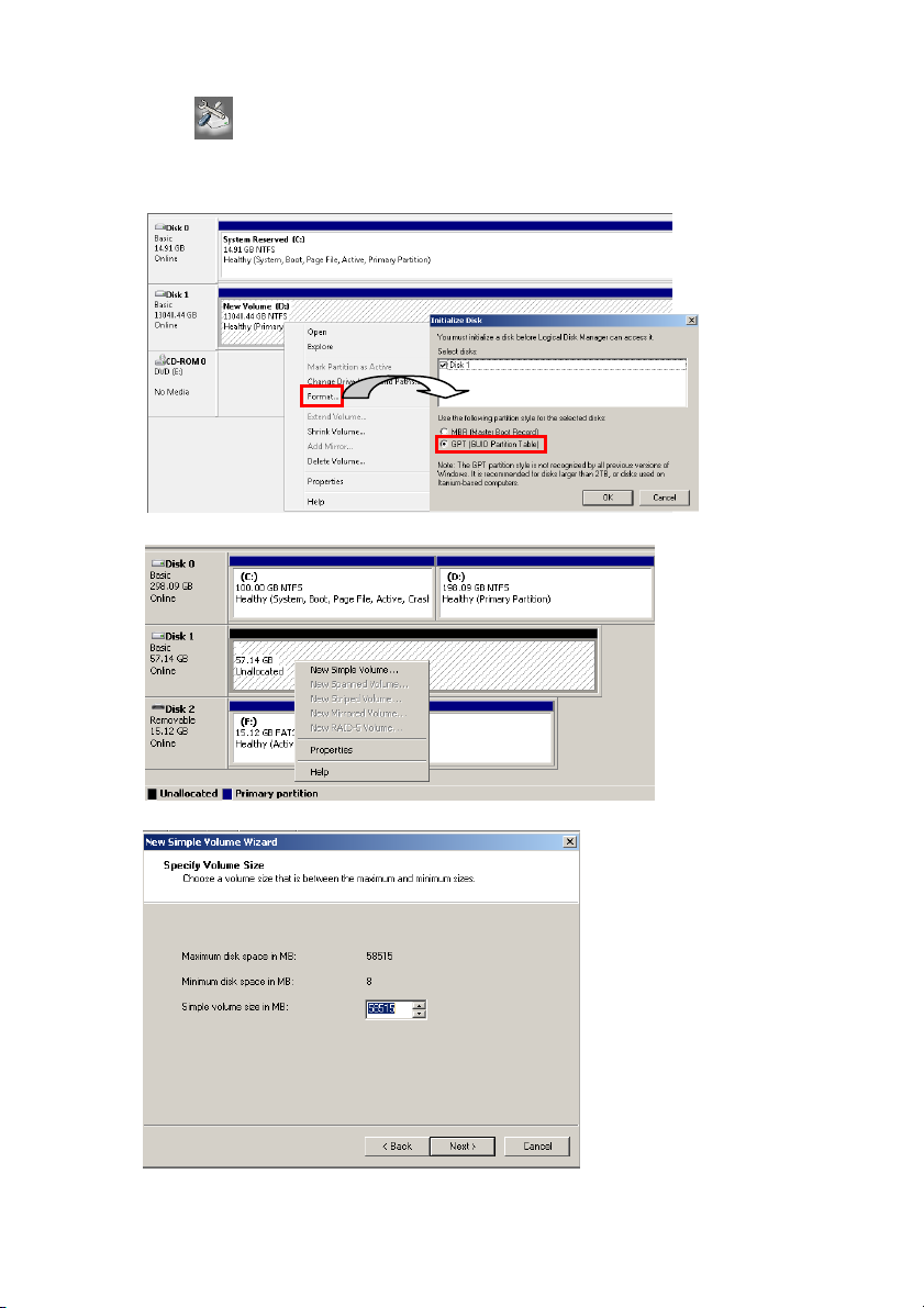
Step 5. Click “ “ button from Control panel the diagram of HDD setting will pop up as
below. Move the Mouse to “Format“ icon and then right click of Mouse, then check “GPT”
section and click “OK” start to format the HDD.
Step 6. Click “ New Simple Volume “ icon, then click “ Next “ icon.
Step 7. Specify volume size which you want to the format for the HDD.
14
Page 15
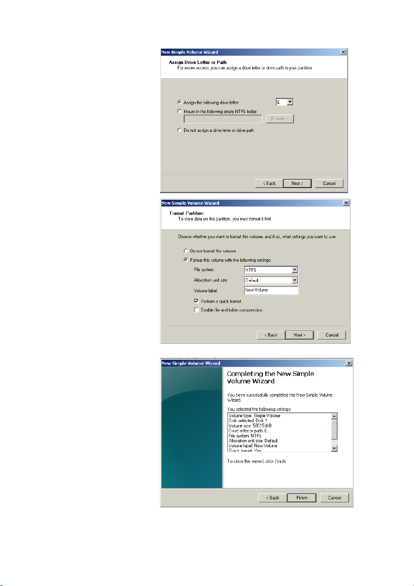
Step 8. Assign drive letter or path.
Step 9. Format HDD partition;
you can refer the setting
as diagram setting as
right side.
Step 10. Click “Finish” button to
finish HDD format.
15
Page 16
Chapter 3. NVR Operating System
After user finish the CPU, RAM and HDD installation, please remember to go to the system Control
Panel to configure the NVR system for installed hardware devices operating properly. For detail about
the setup NVR system configuration in control panel, please refer to chapter 3-1 NVR systems
Control Panel Configuration.
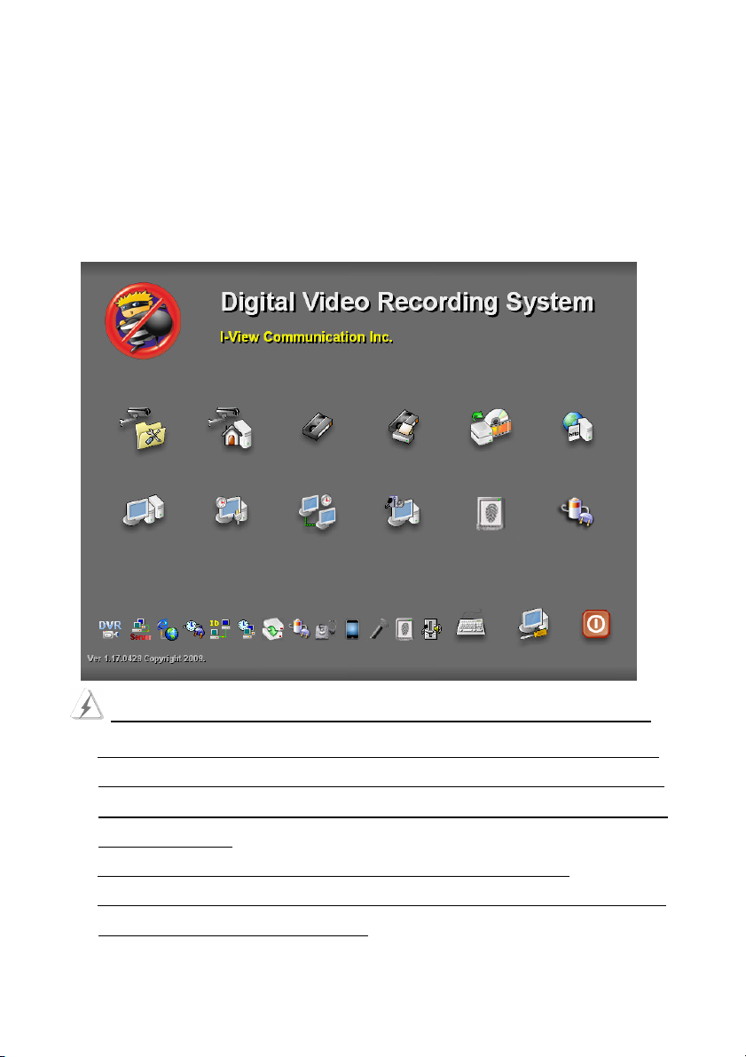
NVR System Main Screen
Take note of the following precaution before you start to configure the NVR system.
1. The AnyNet provides Bar-bond system for the distributor; therefore it does NOT include the
HDD and License of Embedded 7. So you must install the HDD first by yourself. Especially
you MUST buy the license of Embedded 7 from Microsoft, otherwise using the O.S. will
be ILLEGALITY.
2. You MUST obey the rules of Microsoft to process the license of Embedded 7.
3. To avoid the virus problem, please remove the LAN cable and reboot NVR system when you
start to setup the NVR system configuration.
16
Page 17
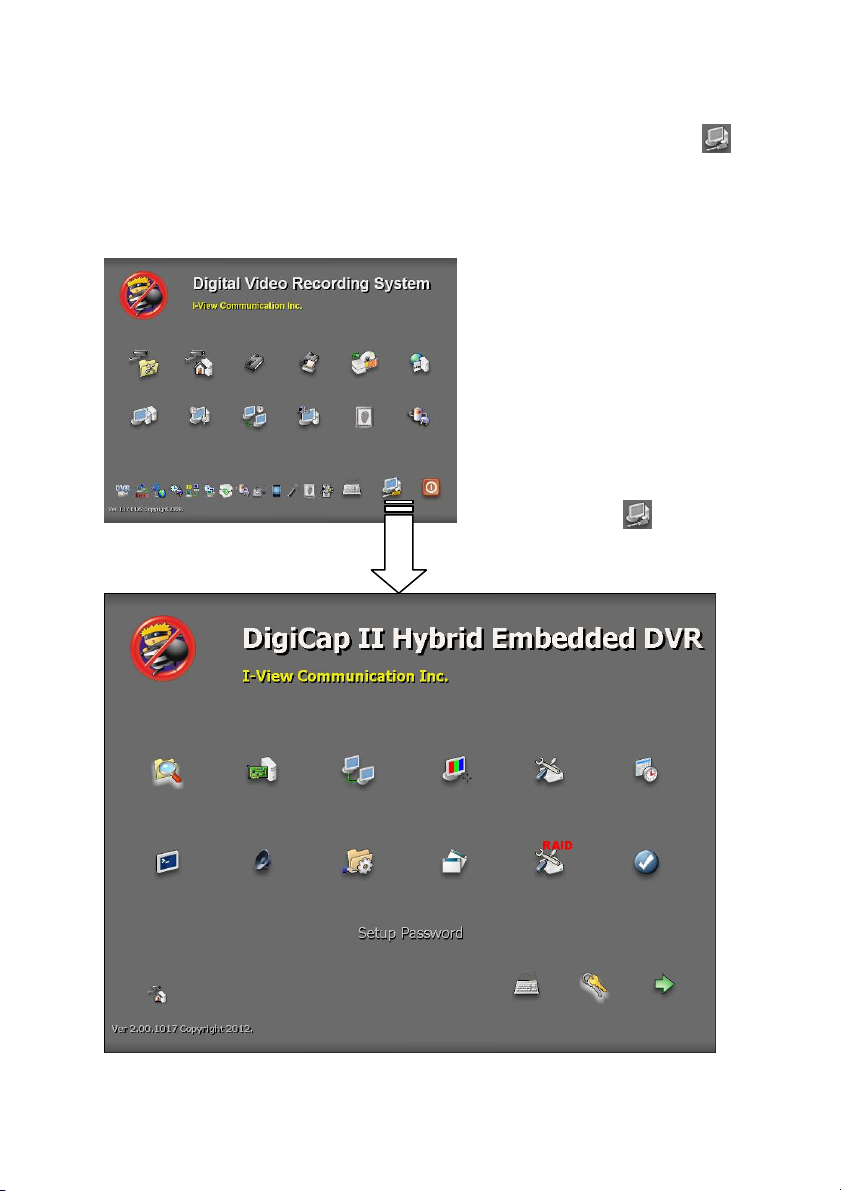
3-1. NVR System Control Panel Configuration
Once user has finished the HDD installation, please click the Control Panel icon ( )
from the right side bottom corner of the NVR system main screen to configure the NVR
system.
NVR System Main Screen
NVR System Control Panel
Control Panel Icon ( ), Please click
to enter the “Control Panel”
17
Page 18
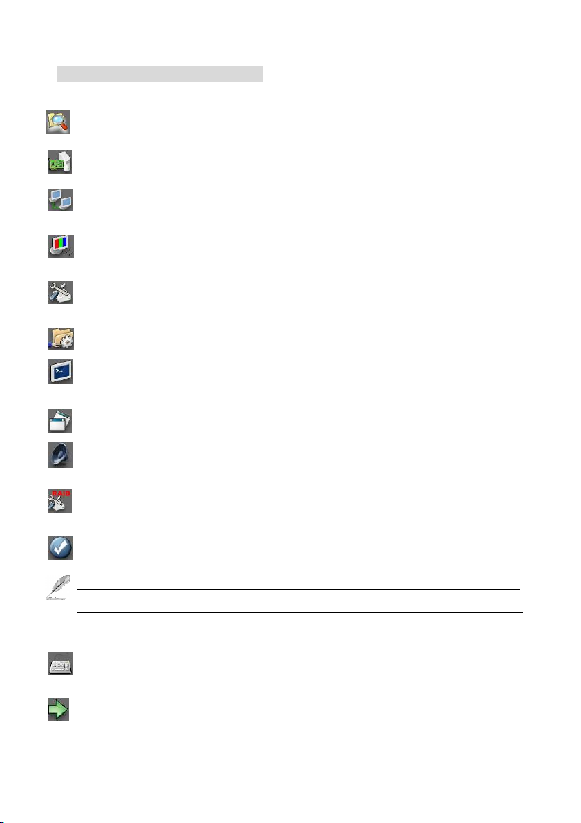
Control Panel Function Description:
File Explore – To select the folder or file.
Device Manager – To check the device driver.
Setup Network Connections– To setup the system network configuration.
Display Properties– To setup the system monitor display.
Disk Management– To format hard disk when you install a new hard device.
Setup Network Firewall– To setup the firewall to protect your NVR.
Command Line – To enable DOS mode to run the command line process.
Application tools – To enable application tools from this icon.
Adjust Volume Control –To adjust the system sound volume.
Setup Raid Parameter– Press to create or maintain Raid HDD system.
Save System Setting– Press to make system configuration change effectively.
The above icons operation process same as Windows 7 except the Setup Raid Parameter, you
can refer to the on-line help document if you have problem. The reset operation process will
show on this manual file.
Keyboard– Click this icon to display a mini keyboard on the screen for words input.
Return– To return to the NVR system main screen.
18
Page 19
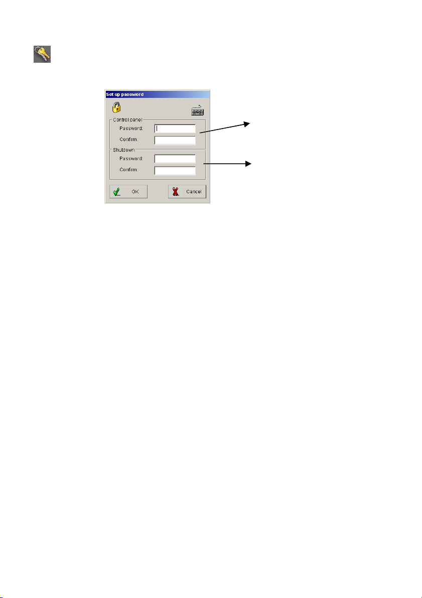
Set up password– Allows you to setup a password to secure the system parameters of the
NVR.
Set up password to access the
control panel.
Set up password for shutdown
the NVR system.
Fig. 3-1.1 Set Up Password
19
Page 20
3-2. NVR Main Program
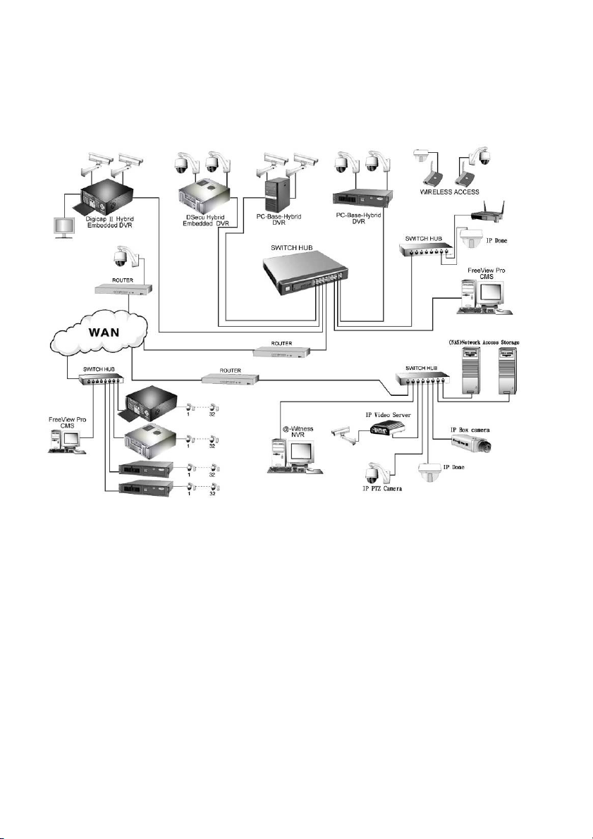
3-2-1. System Configuration Diagram
20
Page 21
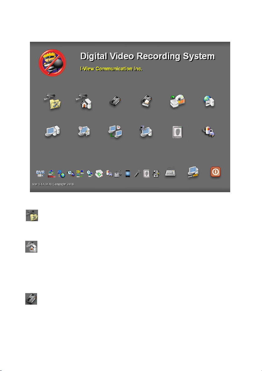
3-3. Program Overview
3-3-1. The main function description:
Video parameters setup - ezSetup: Enable/disable individual audio/video channels and
configure the audio source and video resolution settings.
NVR Surveillance Server – AnyNet: It is the main NVR application software program that
provides on-site live video viewing, scheduled or motion triggered video recording, and much
more. It can also be utilized as a central video server to transmit video streams to a remote PC
via PSTN, ISDN, LAN or Internet (TCP/IP).
Single-file video playback - ezPlayback: An easier-to-use program allows you to playback
your video backups off-site, such as at the police station, but only one file at a time. You can
automatically include this program onto your backup media, see ezBackup for more details..
21
Page 22
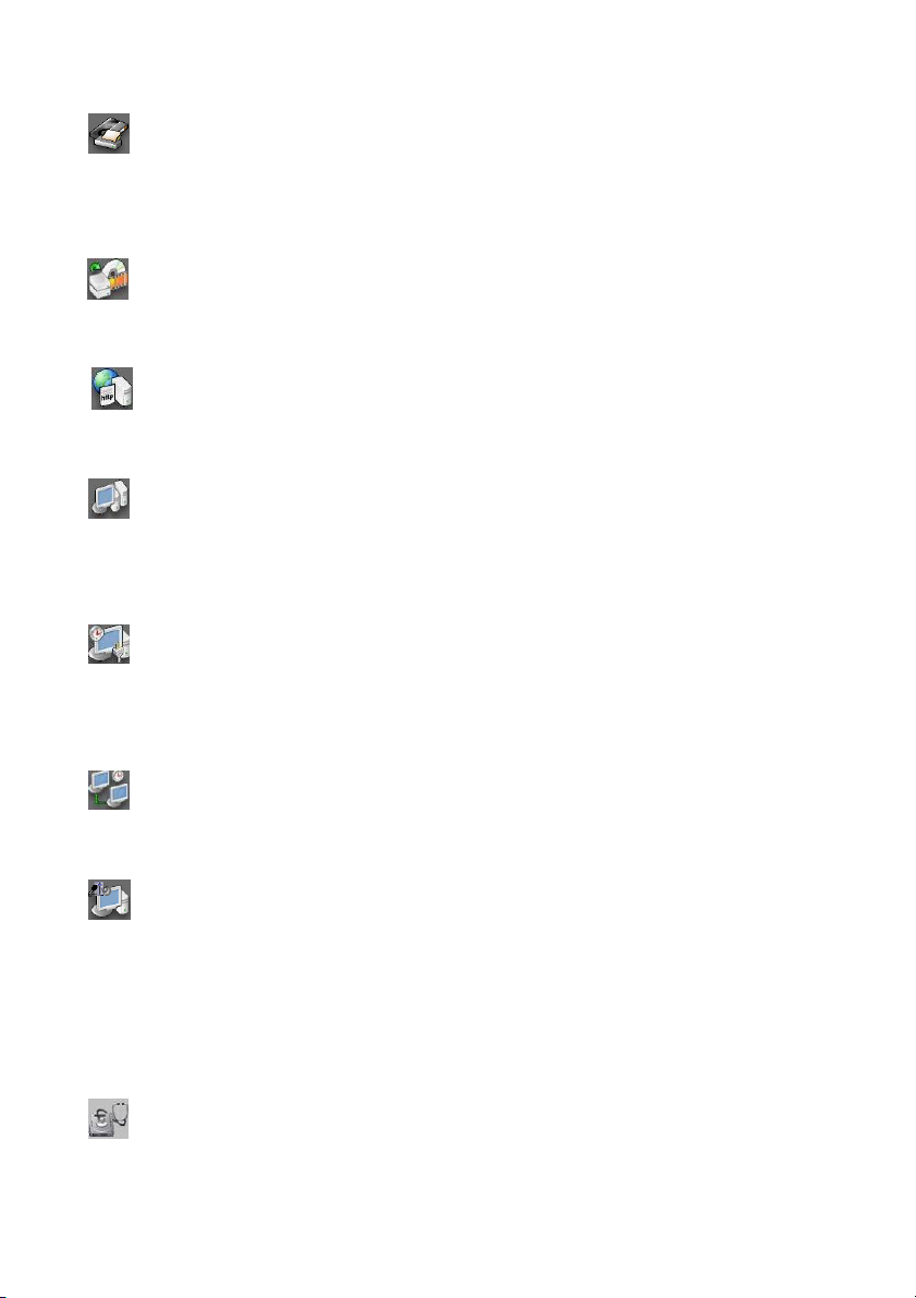
Text insert playback - ezTextPlayback: Playback the recorded video clips with text
transactions. You can search the video by text record or keywords, such as date/time, register,
goods or amount. Please refer to PTI-100 or FAC-500 Operation Manual .
Video files archiving - ezBackup: Share or back up your recorded video clips into other
storage devices, such as a HDD, CD/DVD drive, USB Flash drive, Zip drive, etc..
IE browser server - ezWebServer: View NVR security camera video images via the popular
Internet Explorer browser.
Remote control server - ezRServer: Allow full access to your NVR machine for remotely
technical assitance, or for remotely changing your NVR’s configuration. You must use
ezRClient in FreeView Pro to make the connection between the remote PC and the NVR.
Auto-restart the NVR machine - ezReboot: We recommend to schedule the restart for NVR
machine at least once a week, especially prior to important events, in case you may have exited
the application temporarily and forgot to relaunch it.
Auto-synchronized time - ezClock: Synchronize NVR’s clock with an Internet Time Server.
Please referee to chapter 5-4 for detail setup and operation introduction.
2-way voice communication - ezTalk: Real-time voice communication between the NVR
machine operator and a remote PC technician. Both machines must be equipped with a
microphone and a pair of speakers. The interaction is similar to talk over with a pair of
walkie-talkies. This is especially useful when expensive telephone long distance charges apply
between the two locations.
HDD Health Checkup - ezHDDSmart: S.M.A.R.T. (Self Monitoring Analysis & Reporting
22
Page 23
Technology) along with the HDD’s own inner sensors can detect physical weaknesses of the
hard disk drive. Our ezHDDSmart software program will report the HDD’s current health
status, disk reliability, failure prediction and related statistical information. Please refer to
chapter 5-6 for in-depth details.
Fingerprint Access Controller – ezFingerKey: Manage the system configuration and the
function usage for fingerprint access controller. Please refer to the fingerprint access controller
user manual for detail instruction.
Mobile phone browser server -ezMobileServer: View the camera video in local NVR via the
mobile phone which supports the GPRS, Wifi or 3G function. Such as iPhone, Gphone, Synbia
Phone, BlackBerry, Windows Phone..
Keyboard: Press to display a mini-keyboard for words input.
Control Panel Button: Press to enter control panel interface for system configuration.
Restart/Power Off Button: Press to select restart or power off the AnyNet system.
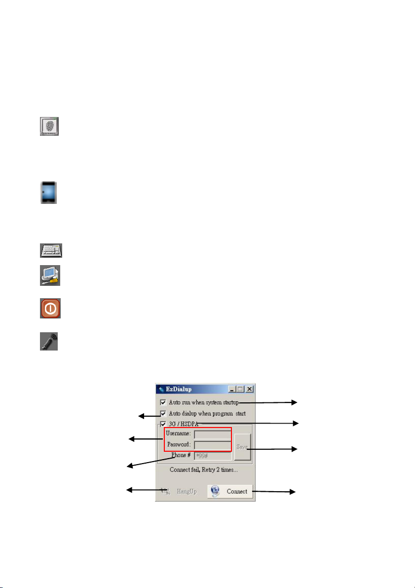
Auto Dialup- ezDialup– Allow you to auto dial up the 3G modem to connect the Internet
when turn on the Witness Pro NVR program.
Auto to Dialup 3G
Entry the password and user
name for auto login
Entry the phone
Hang up the modem
23
Auto enable program when
turn on the DVR.
Enable Modem
Save the setting parameters
Connect to the Internet
Page 24
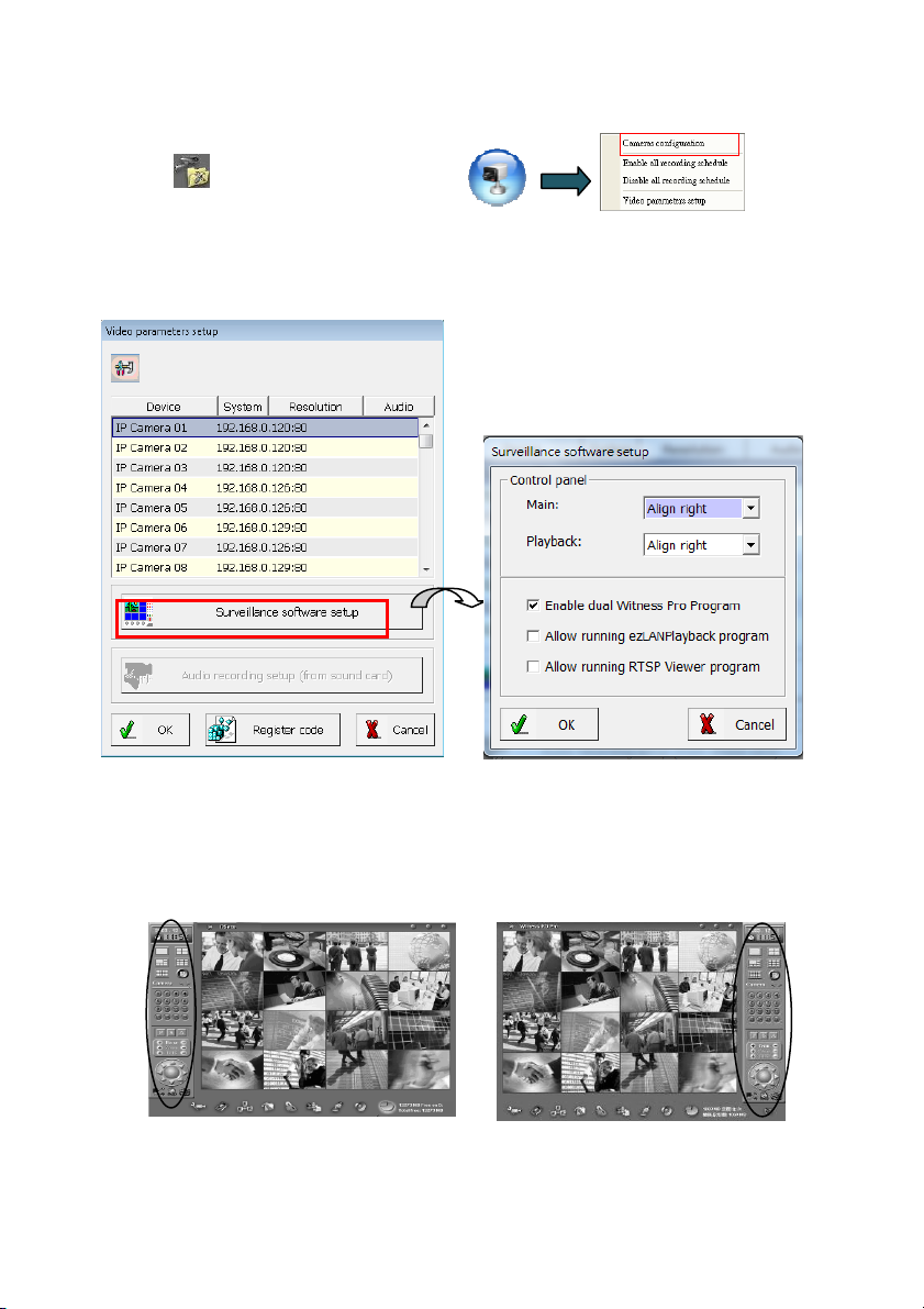
3-3-2. Video parameters setup
Please click icon on the main screen or click
to display the Video Parameters Setup window.
This setup window may differ greatly depending on your NVR model. See the instructions below to
modify the default settings.
1. Surveillance software control panel setup:
The user can change the positions (either left or right of the screen) of the control panels in the
Witness Pro Application. You can individually change the control panel for the live cameras
screen and/or the main playback screen.
Left side video control panel Right side video control panel
24
Page 25
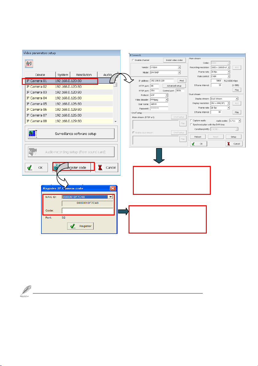
2. Register Code: You can connect to IP camera by Mac ID registration. This is an optional function.
Please contact your vendor for the license code shown as below.
a. Click “Register code” and inform the “MAC ID” for your vendor to get the code.
b. Fill the code and click “Register’. After registering, the number of supported IP cameras will
be shown on “Port” area.
c. Double click the IP camera from “Device list” for setup.
There is no need to have the “Register code” when you use I-View’ s IP Camera.
These settings must match
with the setup of IP camera.
Inform the MAC ID and get
the code from your vendor
25
Page 26
3. Setup the parameters of IP camera
Disable channel: This will disable the selected channel when enable this function.
Install video codec: Install the video codec of this IP camera when you connect IP camera at first
Vendor & Model: Select the correct brand and model for the connected IP camera. You also can
Fig A Fig B
time.
select “Onvif” if your IP camera support Onvif compliant and not on the list. You can check the
26
Page 27

used camera support Onvif compliant from: http://www.onvif.org. Click “ Onvif setup “ icon to
setup the parameters or entry RTSP command code directly which you want to run on the Hybrid
NVR or NVR.
Compress: Select the suitable codec for video recording and transmission.
Recording resolution: Select the resolution for video recording and display.
Frame rate: Select the frame rate for video recording and display.
Rate Control: You can choice video quality or bit rate from this tab. Good video quality or large
bit rate request bigger storage capability.
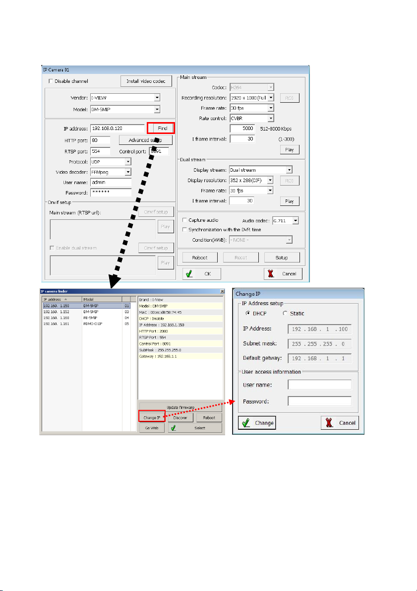
IP address: Entry the correct IP address for the connected IP camera. If you do not know the IP
camera’s IP address, you can click “Find” icon to find out the currently connected IP cameras
User name & Password: The user name and password must be matched the setting of IP camera
which you want to connect.
Find: Click this icon to find out all the currently connected IP cameras on the list. You will find
out the network information of each IP camera. Please refer the diagram shown as above Fig A.
Click the IP address and “Select” icon, the network information of this IP camera will be added for
this channel.
System Firmware update: Click “System Firmware update icon” icon to update the newest IP
camera firmware; you can check and download the newest firmware version from our website:
www.i-view.com.tw .
Change IP: Click “Change IP” icon to setup the DHCP or Static IP address and also modify the
username /Password. Please refer to Fig B diagram. After modification, click “Change” icon
to confirm the setting.
Discover: Click “Discover” icon to research the IP address of system.
Reboot: Click “Reboot” icon to restart this IP camera.
Go Web: Click “Go Web” icon to enable the I.E. Browser to check/setup the detail parameters.
Select: Choice the IP camera which you find out from the system and then click “Select” icon to
assign this IP camera into the camera channel of Witness NVR.
Advance setup: Click this icon will enable the detail parameters setting of IP camera. You need to
load the Active X if this NVR is activated this process at first time.
27
Page 28
The difference IP camera brand has its own “Find” and “Advance setup” setup diagram and
setting process. For the detail information, please refer to the IP camera operation menu.
HTTP port & RTSP port: The both port number must be matched the setting of IP camera which
you want to connect.
Display streaming: You can select the “Dual streaming” or “None” mode; If you select the
“Dual streaming” mode, the live display video will show lower resolution
(320*240/640*480/720*480) for split video and higher resolution (same as recording resolution;
such as 1920*1080) for pop-up to single video on the screen. This Dual streaming mode for live
display can save a huge CPU loading when decoding the video streaming.
Capture audio: You can record sound by microphone from audio input port of IP camera.
Synchronization with the NVR time: Check to synchronize the time of IP camera with NVR.
Condition (AWB): Choice the parameters to suit for the camera install location.
Reboot: Click this icon will reboot the IP camera. .
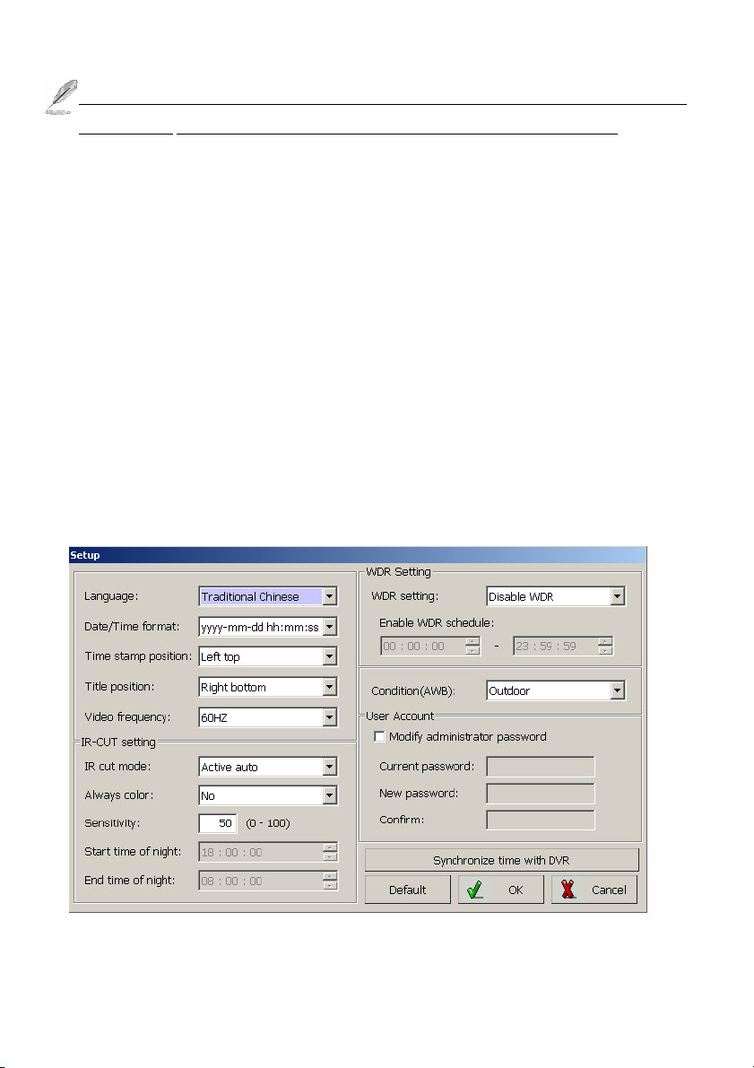
Setup: Click this icon for detail setting of IP camera (refer to I-View’s IP camera); you may not
need to I.E. Browser for the detail IP camera setting. Please refer the diagram as below:
28
Page 29
Chapter 4. NVR Software Operation
16
1
2 5 3
6
4
7 10 8 9 11 12 13 14 15
This chapter describes the functional aspect of the Witness Pro software application.
4-1. Surveillance Server (Witness Pro)
The surveillance server is the primary application program of the I-View NVR systems. It provides
comprehensive CCTV security solutions, including live monitoring, video recording, motion
detection, alarm notifications, E-map for easy site management, events logs, schedule recording,
remote surveillance connection via WAN/LAN/Internet/Intranet, etc. Please see the instructions
below for more in-depth details:
Start the Surveillance Server program:
17
18
29
Page 30
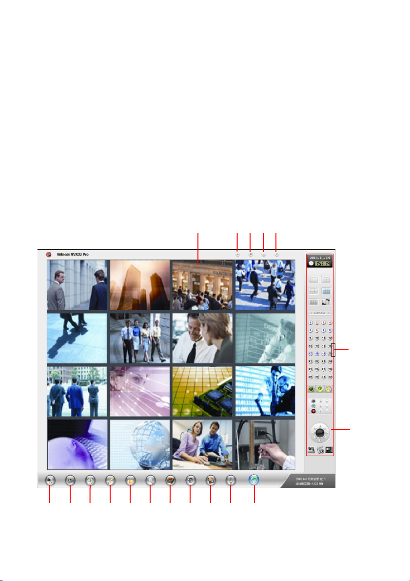
Surveillance Server Functions Descriptions:
1. Login/Logout Button : You can log out as one user and log in as another with different
privileges. The default username is “root” and the default password is “123”. This default user
has full privileges.
2. Exit Button : Exit Witness Pro program. If a crossed-hand icon appears instead, you must
first log out and next log in as a user with exit privilege.
3. Minimize Button : Minimize this program into the taskbar. If a crossed-hand icon appears
instead, you must first log out and log in again as a user with exit privilege.
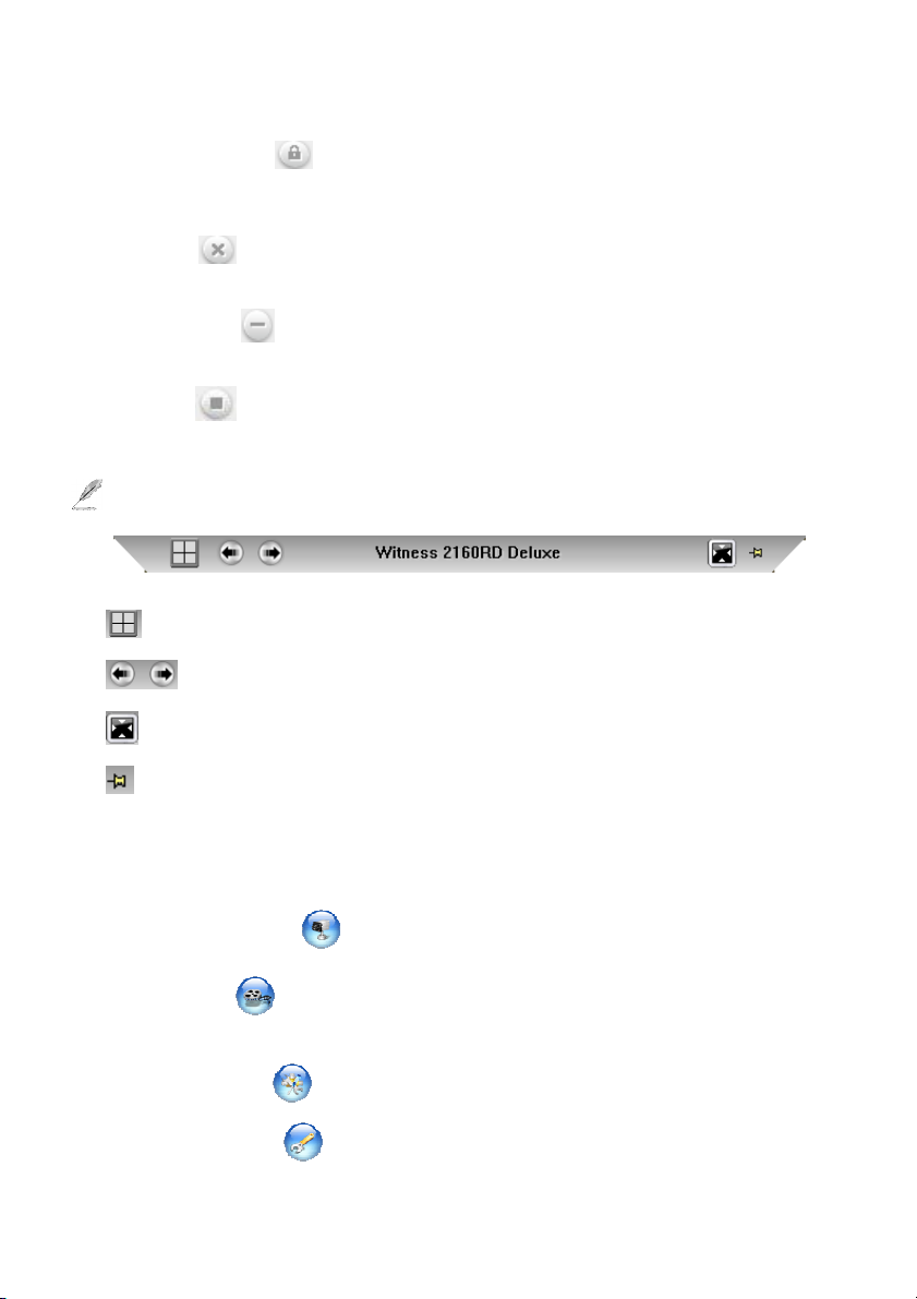
4. Full Screen : Enlarge to a full spilt screen, hide the tool bars and control panel. Or you can
choice the current software screen (Such as eMap, Playback, Split cameras) to show on which
monitor if there are more than 2 monitors connected this NVR.
Please make sure the resolution of both monitor setting is the same.
5.
: Click to select full screen or other multi-spilt screens.
: Click to switch the previous spilt screen or next spilt screen.
: Click to leave full screen and bring back the tool bars and control panel.
: Click to fix this control bar on the screen.
6. Video Display Screen: Display your enabled video channels. Double click on any video channel
to enlarge its video images, and double click again to come back to the initial display mode.
Right-click on any video channel to fine-tune the video parameters, take a snapshot or hide the
current channel’s video images.
7. Cameras configuration : Set up various abilities (e.g. recording methods, alarm Notify,
motion detection, failure notifications, etc.) for each individual audio/video channel.
8. Video playback : Run any of the following playback programs: “Video playback”,
“Synchronized playback”, “Text insert playback”, and “ezBackup”. Please refer to Chapter
3-4 for detail information and setup.
9. Remote access setup : Set up your NVR system network parameters and remote access
capabilities.
10. System configuration : Configure the surveillance server’s main general settings. There
30
Page 31

are three categories including “System configuration”, “Video display configuration”,
“Connection ezDispatch Server setup”, “Save / Load configuration”, and “ezTools”.
11. User access setup : Manage a list of users with different access privileges.
12. Application logs : Review the user logins/logouts, motion detection records, video loss
occurrences, remote user accesses, hard disk failure events, etc.
13. Peripherals setup : Set up new NVR peripheral devices for advanced system integration.
14. Stop Alarm Siren : Click to stop a sounding alarm.
15. Storage Configuration : Define the NVR video storage devices, fine-tune the compression
ratio and configure several video saving parameters.
16. Public Address Configuration : This icon will be enabled when the PAC-800 Public
address server is connected to NVR. Setup the P.A. parameters and announce areas.
17. Real-Time Display Switch : If your NVR model supported real-time display, you can
toggle the real-time display switch “on” and “off” at any time. Switch to the real-time display
mode when you are primarily viewing live video feeds. Turn it to “recording mode” to show
spilt videos on different monitors or "Text on video" when you integrate with POS & Access
Control System. (For CP-2160RD, CP-3160RD, CP-2320RD, and CP-3320RD only).
18. Video display switcher : Click this tool bar to shown the Channel 33 - 64 videos
(analog /IP cameras) or all IP cameras when you using the 64 channels NVR or Hybrid NVR.
(Hybrid NVR) will show on the second monitor.
19. Video Control Panel: On the right-hand side you have many display/recording control buttons,
several PTZ camera control buttons, a TV channel selection list and a visual e-Map utility tool.
Please refer to Chapter 4-13 for detail instruction.
20. Hide The Toolbars: Press the “ESC” key of your keyboard to hide the toolbars and control panel.
Later, you will have to press on the “ESC” key to bring back the toolbars and control panel. If
you have previously set “auto log in” within the system configuration, you may have to press on
the “Alt-F4” or “Alt +I” key combination on your keyboard to bring up the login screen. This
will allow you to first log in as a user with administrative privileges, so as to be able to bring back
the toolbars and control panel.
Individual video channel attributes and functions:
To access the available video tools, right click one of
the video channels currently displayed to bring up a
small window shown as the picture.
Hide video: Blank out the currently selected
video channel from the main screen while any
31
Page 32

recording sessions would not be affected.
Announce: Allow announcing to
this camera directly when the
user need to announce
information for cover area of this
camera. This function just effects
when the NVR connects the
Public address server or this
camera is IP camera type.
Audio input from: Choice the audio input from the Sound card if installed more than one.
Speak voice format: Select speak out voice format.
Transform voice format: Choice different compression format for the audio converter.
Adjust volume: Adjust the audio volume for the announcement.
Start / Stop: Enable and disable the announce function. .
We are strongly recommend to install dual sound cards on the NVR system for the announce
purpose. One sound card for alarm purpose on the NVR site, another sound card for
announces or 2-Way audio function between the NVR and camera.
ePTZ: Press this icon allows to enable digital Pan / Tile / Zoom function and control via ePTZ:
Press this icon allows to enable digital Pan / Tile / Zoom function and control via mouse.
The process is described as below:
Click the right button of Mouse and press the “ ePTZ” icon to enable Digital PTZ (Pan /
Tile / Zoom) function and click again to disable.
Move the Mouse to the video which you want to control this camera with Digital PTZ.
Click the roller of Mouse and the click any point of image, the image will move to central
area and zoom in (The IP camera will pop up video at a time, but analog camera will not).
Click the roller again will go back original video position.
Keep on pressing the left button of Mouse and moving the Mouse to left /right/ up/down
position, the image of video will follow up the moving direction. Scroll up the roller of
Mouse to zoom in video and scroll down the roller to zoom out video.
32
Page 33

PTZ: Press this icon allows using the Mouse to control PTZ cameras for the Pan / Tile / Zoom
function from image directly. The process is described as below:
Click the right button of Mouse and press the “PTZ” icon to control PTZ (Pan / Tile /
Zoom) function from image directly and click the icon again to disable.
Move the Mouse to the video of PTZ camera which you want to control. Keep on
pressing the left button of Mouse and moving the Mouse to left /right/ up/down position,
the PTZ camera will follow up the moving direction. Scroll up the roller of Mouse to
zoom in video and scroll down the roller to zoom out video.
Instant Playback: Playback instantly the
latest recorded video.
Play: Play video.
Stop: Stop playing video.
Snapshot: Capture the video screen
and save as a BMP or JPEG file.
Resize: Resize the video chip.
Navigation Bar:
Display the current position of the video clip and allow users to move the video clip in
different points. Left moves backward, right moves forward.
Duplicate to: Duplicate this selected channel to show the video on the second monitor, if the
NVR support dual monitors. This function just can be enabling when the NVR/NVR
connected 2 monitors.
Clear border: Remove the surrounding red border around the currently selected video
channel. Please note that this red border only shows up upon motion-triggered recording.
Zoom in: Magnify the live images of selected video channel. Once you have zoomed in the
video display, you can navigate throughout the enlarged viewing area by simply dragging the
video images to any direction you wish, while holding your mouse left button.
Zoom out: Zoom out the live images if needed after zoom in.
Clear zoom: Return back to the original view display.
Adjust Image Colors: Adjust the brightness, contrast, saturation, and hue levels for the
33
Page 34

selected video channel’s live images.
Default: Bring back to the original settings.
Swap with: Swap the on-screen positions of two different video channels. For example, if you
wanted channel #1 to appear at
position #15 and vice versa.
Exit: Click this button to exit the
video tools window.
Snapshot: Take a single picture of
the selected channel’s live image and
save the snapshot picture in the disk.
Adjust image colors: Adjust
the image contrast level and edit the
picture within the snapshot picture.
Normal: Return to the original color format of the snapshot picture.
Save a file: Save the current snapshot picture in the disk (diskette, hard disk, USB flash
drive, etc) in either BMP or JPG file format.
Print: Print out the current snapshot picture if the printer is available.
34
Page 35

Use Fisheye IP camera for 360°/180° Panorama viewing:
The Witness Pro software
provides the 360°/180° Panorama
viewing function for our fisheye IP
camera (FE-5MIP-F01). To access
the Panorama video tools, move and
right click the Mouse on the
currently displayed video channel of
Fisheye IP camera to bring up a
small window shown as the right
picture. Click “Panorama video
setup “ icon you will find out the
setting parameters. There are multi
modes video displays for difference
application. The fisheye IP camera
will show the original video on the
screen when show split video on the
screen; double click the fisheye
camera video will pop up the selected video mode on the screen.
The system provides the manual and auto ePTZ function, the process description as below:
via ePTZ: Press this icon allows to enable digital Pan / Tile / Zoom function and control via
mouse. The process is described as below:
Select the display mode which you want to show on the screen, then move the Mouse to
Source image and keep on pressing the left button of Mouse and moving the Mouse to left
/right/ up/down position, the image of video will follow up the moving direction. Scroll
up the roller of Mouse to zoom in video and scroll down the roller to zoom out video.
35
Page 36

4-2. Logging in the Surveillance Server
To log in as a user, click the button from the top-right corner of the Witness Pro surveillance
program. You can also change the username and password when you login. To log out, simply click
the same button. The default login username and password are “root” (lowercase) and “123”
respectively. That default login profile may be interchanged with your own (recommended).
Login
Logout
36
Page 37

4-3. Camera configuration
Advance
Camera selection
camera.
display
text.
microphone.
display selection.
4-3-1. Camera configuration:
General: This menu tab is primarily used to set up the OSD options (which text overlay to show in the videos)
and name the locations of the installed cameras. To access this setup section, simply click the “General” tab
at the top from the “Cameras configuration” window.
Select if display
camera information in
playback clips or live
vido & playback clips.
Camera information
display selection.
Camera date format
This number must
be matched the
connected PTZ ID.
PTZ camera control
protocol selection.
Duplicate another
camera’s settings to
the current camera.
Click “
camera return to a default preset position after
system reboot or inactivity for a certain period.
Default operation: Select “Auto scan”,
“Preset scan”, or “Go to preset”
Preset assignment: Select camera for “Go to
preset”
” button to enable your PTZ
Type camera
location and select
the type and view
direction of the
Set up color, font,
and display text
position for the
Enable watermark
function and can
select another image
for watermark.
Listen to live
audio via a 2Vp-p
Confirm and exit.
37
Page 38

Recording:
current camera.
Camera selection
This menu tab is primarily used to set up the video & audio recording functions. To access this setup
section, simply click “Recording” tab at the top of the “Cameras configuration” window.
Activate the
recording schedule.
Activate audio recording.
This function is only
available with audio
capable NVR models.
Due to predictable
system failure, the
recording frame rate
may drop substantially.
When “Check frame
rate” is lower than
setup, NVR will pop
out the notification
message automatically.
Duplicate another
camera setting to the
Confirm and exit.
Set up video recording
schedule.
Set up as a maximum
video streaming file size
determined by minutes
or hour.
Select frame rate for
instant recording.
(Same as preview =
The recording speed
will be based on the
NVR model’s
maximum recording
rate)
Creating a recording schedule:
The main purpose of a recording schedule is to determine if the NVR should record as “continuous
recording” or “motion triggered recording”. Click from “Recording” tab to bring up
the “schedule setup” window. Please note if the user check “Enable recording schedule” only without
setting the schedule, the NVR will record the videos for 24 hours.
Section 1:
Camera: Choice the camera which you want to setup the recording schedule and mode.
Continuous recording: Non-stop record videos.
Motion triggered recording: Record only upon motion detection. You can also select “No
38
Page 39

motion recording” as well to record continuously no matter the motion is triggered or not.
Hybrid recording: Record high frame rate only upon motion detection and non-stop recording
with slow frame rate without any triggered. You can select the frame rate from “No motion
recording” tab as well to record continuously no matter the motion is triggered or not. Using
this recording mode can save the HDD capability without losing any video clips.
7
8
1
2
3
4
39
5
6
Page 40

Section 2:
Type: The user can set up recording schedule for “Daily”, “Weekly” or “Special duration”.
Start time & End time: Set up time frame for recording schedule. Here’s a classic sample
recording schedule: “motion triggered recording” from 00:00 to 07:59; “continuous recording”
from 08:00 to 16:59; “motion triggered recording” from 17:00 to 23:59.
You should always set your complete schedule start at 00:00 and end at 23:59. Never overlap
the time entries, such as from 00:00 to 12:00 and from 12:00 to 23:59. It should start from
00:00 to 11:59 and 12:00 to 23:59.
Start date & End date: Select dates for recording in “Special duration”.
Section 3:
Frame Rate: You can set up the recording frame rate for each individual schedule entry.
If you set the recording frame rate higher than what your NVR can physically record, the
recording frame rate will be the maximum your NVR can record.
No Motion Recording: This option is only available under the “motion triggered recording”
mode. When it checked, you can record the videos even if no motion is triggered in case any
incidents. It is advised to set a much lower recording frame rate here to save disk space.
Save pending live videos when motion is triggered: When motion is triggered, the pending
video stream will automatically be saved as a file and subsequently the motion triggered video
stream will be saved into a separate file. This segregation makes your motion triggered playback
videos easier, but you may somewhat inadvertently truncate the beginning of the motion
triggered videos, mostly when you do not enable the pre-recording function or when you set the
motion sensing sensitivity too low. The pre-recording function and motion sensing settings will
be discussed later on in this chapter.
Section 4:
Schedule entries list: This is a list of the set recording schedule entries. To edit one of the listed
entries, simply double click the entries appearing in the list. Once the editing is done, you may
click “Save” button to save your changes or the “Exit” button to discard your changes. To delete
entries, simply highlight the scheduled entry and click “Delete” button.
40
Page 41

Section 5:
The Witness Pro NVR system provides intelligent video detection functions and the description
as below:
Motion setup:
The user will be fine-tuning
how the NVR starts
recording if people or
objects are moving in the
angle of view. To access this
section, simply click
“Motion setup” from
“Select detection” drop bar.
There are “Software
detection” and optional
“Hardware detection”. For hardware motion detection, the user will need to purchase a PCI
I/O board or use the I/O ports f IP camera to connect its existing burglar alarm motion detectors.
The motion setup can only take effect if the user selected “motion triggered recording” from
the recording schedules. (See “Schedule Setup” from “Recording”). The user can verify if you
have properly activated the recording schedule for certain cameras from its number button on the
“Video control panel”. The camera number shall appear as light blue (scheduled to record) or
red (currently recording).
Software Detection – You can select and frame multiple areas in the view of the camera for
software detection. This function will help you save disk space, but it will also produce multiple
false alarms. Consider hardware detection for better performance.
Sensitivity Level –You can adjust the sensitivity of the software motion detection. Simply move
the slider bar to right side for increasing sensitivity level or to the left side for decreasing it.
When you choose a level of motion sensitivity, you shall take into consideration unavoidable
movements. For example, if you have a blowing fan nearby, it may produce some sort of
motions in the video. Adjusting the sensitivity properly will filter out this issue.
41
Page 42

Areas Setup – Select or frame the specific areas from the view of the camera for motion
detection.
To add a new area of detection, please follow the steps shown as below:
Step 11. Flame and drag on the video image to select the desired detection area by your mouse.
Step 12. Click button to add the new selection.
Step 13. To set up others detection areas, repeat step 1 and 2.
Step 14. Choice the sensitivity level for the detection.
To delete a pre-set detection area, follow the steps shown as below:
Step 15. Select a detection area by right clicking on it. This area will become blue.
Step 16. Click “Delete area” button. This area will be disappeared from view.
Step 17. To delete other detection areas, repeat step 1 and 2.
If you don’t define specific detection areas, the entire view of the video will be the detection area.
Hardware detection (Optional) – You can use hardware detection for more accurate motion
sensing. For example, light changes do not trigger false alarms, but it does with software detection.
You can select a motion-sensing device from “Triggered by” drop-down menu. Once you connect
the sense devices at the “Sensor in” ports of the optional “inputs board” (NVR add-on) or IP
camera, a motion sensor will be triggered due to detected movement in its track and the assigned
camera will automatically create an alarm and start to record.
Illegal parking setup: (Optional)
42
Page 43

The system allows detecting the illegal parking, please following the steps shown as below to
process of detection illegal parking.
Step 1. Choice “Illegal parking” item from “ Select detection” drop box.
Step 2. Setup the parameters for illegal parking detection.
• Choice the sensitivity level for the detection from 1 to 5 (1: Lowest; 5: Highest).
• Select the speed of buildup background.
• Choice “Scene change level” to suit for application area.
• Delay time: The trigger must be continued and longer than setting period, then the event is
valid.
• Stop recording: The video will keep on recording the period of setting after the trigger is
stopped. The setting number is zero, the video recording never stop when triggered.
• Highlight alert box: Check this function the detection frame will be flashed when
triggered.
Step 3. Click “Detection area“ section, then flame and drag on the video image to select the
desired detection area by your mouse.
Step 4. Click button to add the new selection.
Step 5. To set up others detection areas, repeat step 3 and 4.
Step 6. Entry the number of “ Width” and “ Height “ to select the desired detection object size.
Object detection setup: (Optional)
The system allows detecting the illegal parking, please following the steps shown as below to
process of detection illegal parking.
Step 1. Choice “Object detection” item from “ Select detection” drop box.
Step 2. Setup the parameters for illegal parking detection. The parameters function detection,
please refer to the illegal parking detection section.
Step 3. Click “Detection area“ section, then flame and drag on the video image to select the
desired detection area by your mouse.
Step 4. Click button to add the new selection.
Step 5. To set up others detection areas, repeat step 3 and 4.
Step 6. Entry the number of “ Width” and “ Height “ to select the desired detection object size.
43
Page 44

Section 6:
Alarm Tolerance – You can define the acceptable movements to prevent false alarms movements.
For example, if the tolerance is set to 2, the movements in the video must be occurred at least three
consecutive times to trigger alarm and start to record this video channel.
Post recording – You can set the duration to continue recording after motion is no longer detected.
If the duration is between one motion detection occurrence and a subsequent motion detection
occurrence, the two instances will be combined into one alarm/recording session.
Pre-alarm - The camera will start a new motion triggered recording session at least 1~99 seconds in
advance when the event occurs. The pre-alarm recording video will save into the HDD with about 2
FPS recording rate speed.
Section 7:
Actions to take upon motion detection: This section will allow you to set up what the NVR
software should act when the motion detection is triggered. Please refer to the introduction below
for setup details:
Save your audio
selection and exit the
setting
Play a siren or your
voice message.
Exit without saving
your audio selection.
44
Select an audio file
for alarm siren.
Halt the current
playing session.
Record your voice
message via your
PC’s microphone.
Page 45

Enable Pop up video: (For Hybrid DVR only)
Enable alarm siren: The NVR can sound an alarm upon motion detection. Make sure your
NVR is equipped with a pair of PC speakers. Click button for setup.
Enable notification: Notification by phone
call, SMS message, email notifies, upload to
FTP server and live videos transferred to a
remote site PC when motion detection is
triggered.
Notify by Video transfer: Upon motion
detection, the NVR system will automatically
send and record the selected live videos to a
remote PC (with FreeView Pro standby).
Please follow the steps below for set up.
Click “Video transfer” tab.
Step 1. Check if the user would like to send
the live video to “ezDispatch Server” and
distribute the live video to the available CMS platform. This function for a large system and
the control center has more than CMS platform.
Step 2. Check if the user would like to send the live video to “ezDispatch Server” and
distribute the live video to the available CMS platform. This function for a large system and
the control center has more than CMS platform.
Please make sure the ezDispatch had been enable or not when you want to use this
function.
Step 3. If the user would like to send the live video directly to remote PC, type the remote PC’s
IP address or DNS address.
Step 4. Enter TCP/IP port number (default port “1501”) for the transfer connection.
Step 5. Determine the Transfer duration in minutes.
Step 6. Select the desired video channels to transfer the live videos to remote site PC.
Step 7. Click “Save” button to save your pending entry, which will be listed at the bottom of
this window.
Step 8. Repeat steps 2 through 6 to add another “Remote” transfer live video notification entry.
The TCP/IP port number you choose must match the one setup in FreeView Pro program
45
Page 46

at the remote PC; otherwise the connections will be failed. Please note you also need to
open from your router configuration for remote PC. Check your router manual for more
info about “port forwarding” or “virtual server”.
Notify by Email: Upon motion detection, the NVR system will automatically send e-mail
messages to the registered email recipients. Please follow the steps below to set up e-mail
notification entries.
Step 1. Click “E-mail message” tab.
Step 2. Enter the SMTP server address
provided by your ISP.
Step 3. Type the default port “25” for
connections.
Step 4. Enter the email account and
password for sending the
notification emails.
Step 5. Type the email address for sending
the notification emails in “From
mail” field.
Step 6. Type the email address for receiving the notification emails in “Mail to” field.
Step 7. Fill “Subject” and “Message” fields to identify the email messages.
Step 8. Check if the user would like to receive the attached snapshot picture.
Step 9. Click “Save” button to save your pending entry. That entry will be listed at the
bottom of this window.
Step 10. Click “Test mail” to check if the setting is correct or not.
Step 11. Repeat step 2 through 6 to add other E-mail message notification entries.
Notify by FTP server: Upon motion detection, the NVR system can send the trigger
message to FTP server and save the trigger information as a text file. You will get the
trigger information from the file such as DVR/NVR Name, Camera number, Event and Time
46
Page 47

stamp. Please follow the steps below to set up FTP server notification entries.
Step 1. Click “FTP notify” tab.
Step 2. Enter the DNS name and port
number (default is port 21) which
the user wishes to send the
triggered information to this FTP
server.
Step 3. Entry the “User name” and
“Password” of FTP server for
login.
Step 4. Enable “ Passive mode” for some
special FTP server. Ask your
MIS staff for the detail setting.
Step 5. Entry the saving path and check “Attached image file” icon, if you needed.
Step 6. Click “Save” button to save your pending entry. This entry will be listed at the
bottom section of this window.
Step 7. Repeat step 2 through 4 to add other phone call notification entries.
Notify by Phone Call: Upon motion
detection, the NVR system can dial the listed
phone number(s) and play a recorded
message or siren. Please follow the steps
below to set up phone call notification entries.
Before setting up for phone call notification,
please refer to “System configuration” for
dial-up voice modem setup first.
Step 8. Click “Phone call” tab.
Step 9. Enter the phone number the user
wish to call.
47
Page 48

Step 10. Click “Sound File setup” button to choose an alarm siren or to record your own
voice message.
Step 11. Click “Save” button to save your pending entry. This entry will be listed at the
bottom section of this window.
Step 12. Repeat step 2 through 4 to add other phone call notification entries.
1. If the user would like to record his own voice message, the “.WAV” file format must
be 8000Hz, 16-bit and Mono for phone call notify.
2. If the user would like to setup the phone notification wave file from the system file, the
warn.wav file should support 8000Hz, 16-bit and Mono format.
3. Each phone call notification entry can have its own unique audio stream, and each
phone call automatically disconnects after one-minute duration even if your voice
message is longer than one minute.
4. You must use an approved Voice Capable Dial-Up Modem.
5. If the user’s telephone system requires an extension number to be inputted, please use
one or several commas (,) to separate the phone number and the extension number.
The number of commas requirement depends on the system, so test it beforehand.
Notify by SMS message. Upon motion
detection, the NVR system will
automatically send the SMS message to
the registered mobile phone. Please
follow the steps below to set up SMS
message notification entries. Before
setting up for SMS message notification,
please refer to “System configuration”
for 3G modem setup first.
Step 1. Click “SMS message” tab.
Step 2. Enter the mobile phone number.
48
Page 49

Step 3. Type the SMS message.
Step 4. Click “Save” button to save your pending entry. That entry will be listed at the
bottom section of this window.
Step 5. Repeat steps 2 through 5 to add another SMS message notification entry.
You must use an approved 3G Modem for sending SMS message to mobile phone.
Shift PTZ position: Upon motion detection, the
PTZ camera can automatically move to the
aiming position(s) of one or more or whatever
the preset position(s) the user has defined. Please
define the preset position from “Video Control
Panel” before setup. For more information about
PTZ installation, please refer to the RS-485
control card (e.g. NC-3213USB) user manual.
Step 1. Select a PTZ camera from “Camera”
drop-down menu in the “Move to preset
position(s) when triggered” section at
the top.
Step 2. Select a preset position from “Aim to” drop-down menu in the “Move to preset
position when triggered” section at the top.
Step 3. Click “Save” button on the right to add your new entry to the list.
Step 4. Repeat step 1 through 3 to add other PTZ cameras to move upon motion detection.
For “Return to preset position(s) when stop trigger” setup, please follow the same procedures
with the “Move to preset position(s) when triggered” section.
Alarm zones setup: This function can be enabled when the public address server connected to
the NVR. The public address server will announce to the camera site via group(s) or zone(s)
automatically when the NVR is triggered. Follow up the steps shown as below to setup
announcement area:
49
Page 50

Select announcement
Plays chime sound
before alarm voice
Adjust alarm voice
volume
area by zone and
group
Step 1. Choice “Zone” and “Group” where will announce when NVR is triggered. The detail
setting process of “Zone” and “Group”, please refer to “Public address configuration”
chapter.
Step 2. Record or choice the existed alarm sound files and setup the interval period between files
and press “Add” icon to save the file. Click the selected files and click “Delete” to
remove the selected alarm sound file.
Step 3. Enable chime sound if you want to play chime sound before alarm sound.
Step 4. Adjust the audio volume for play alarm sound.
Step 5. Click “Save” or “Cancel” icon to finish and exit the setting process.
Trigger output relays: The user can select the output relays from Relay 01 to 13 in
“Controller board” or select the output relays from each IP camera or NC-180AZ PTZ
receiver module.
Record/Play alarm
sound file
Browse /Select the
existed sound file
List selected alarm
sound files
List selected zones
and groups
50
Page 51

Video Loss
The NVR can send an alarm or other kinds of
notifications if there is any video signal loss from the
camera; either due to the problem of power supply or
bad video coaxial connections. To activate this
function, click “Video Loss” tab and follow the
instructions below:
Enable alarm siren: Set up an audio warning
siren sound (or recorded voice) when video loss
51
Page 52

occurred on this camera.
Enable notification: Each camera can have its own unique setup for notifications when video
loss occurred.
Shift PTZ position: Set one or more of your connected PTZ cameras to move for one or more
preset positions when video loss occurs on this particular camera.
Trigger output relays: Select the output relays from Relay 01 to 13 in “Controller board”
(NC-3213USB) or select the output relays from each NC-180AZ PTZ receiver module when
video loss occurred. The NVR can automatically turn ON external devices (such as siren horns,
strobe lights, ceiling room lights, etc.) when video loss occurred on this camera.
POS & Access Controller (Optional)
If the NVR is integrated with POS system and Access Controller, the text of POS and Access
Controller can be displayed on the screen and recorded with the video for specific video clip playback
search easily. After installing the hardware of POS text inserter system and Access Controller, please
click “POS & Access Controller” tab from “Camera configuration” and follow the instructions
below for setup.
52
Page 53

Font: Click icon to specify the font size of text on the video clips.
Clear: Click icon to erase the POS text shown on the current monitor.
Text data show on “Monitor + Video clips”: Enable to display the text from POS or Access
Controller on the connected monitor, video clips and remote PC. Please go to “General” tab and
select “Monitor+clips” from “Shown on” to enable this function. After selecting
“Monitor+clips”, all this function will be automatically selected.
POS / Access Controller setup:
1.) Printer model: Select printer model that is used for your POS system.
2.) Search keywords setup: Setup Keywords for searching text video clips.
3.) Printer commands setup: The NVR is
able to process certain functions after
receiving the printer command code,
such as “Record events when cash
drawer opens”.
4.) Access Controller: Select a connected
fingerprint access controller to capture
the access record text for the video clips.
5.) Save insert text: The user can select
Please type specific keywords from 1 to 10
columns for searching text on videos, and
press “OK” button to save the setting.
53
Page 54

“Always” or “Never” to determine if the status of inserted text.\
6.) Keep text records: Setup the retained period for text. This text record will be shown on the
“Text insert Playback” and used for searching text on videos.
7.) Enable video recording when transaction starts: The NVR will start to record when the
transaction starts and specify the recording duration when the transaction stops.
8.) Clear text over screen when transaction ends: The NVR can clear/clean up the text over
the screen after the specified duration when the transaction stops.
9.) Text position: Select the display position of text on the video.
10.) Text color: Select the display color from each line of the text.
4-3-2. Enable / Disable all recording schedule
After setup for camera recording schedule, you can enable or disable the recording from here.
Enable all recording schedule: Click to enable all recording schedule (Continuous recording or
Motion triggered recording) for each camera. If there is no preset schedule, the NVR will enable
instant recording for each camera in 24 hours.
Disable all recording schedule: Click to disable all recording schedule.
4-3-3. Video Parameters setup
Click this tab will enable the “ ezSetup “ program and then you can change the video parameters, after
finish the parameters setting that the Witness Pro program will reboot automatically to become
effective the parameters setting.
54
Page 55

4-4. Video playback / Synchronized playback / Text insert playback /
5 6 7
ezBack
4-4-1. Synchronized playback
10
9
8
1
2
3
4
Function descriptions of Synchronized playback:
1. Split screen display modes section: Select the split screen display mode
2. Camera selection of the video clips: Select the playback cameras from the selected video
clips folder.
3. The video clips deletion: Delete the video clips from the hard drive.
4. Video streams searching calendar: Search the video clips by date. The red color button of the
date indicates recorded video data.
5. Cameras switch: Click “Up” and “Down” buttons to display the video stream of the cameras.
6. Playback toolbar: Provide powerful functions for user to view and search the playback video
55
Page 56

clips.
7. Video stream searching bar:
0~23 (Hours) selections: Search the video stream data by hours.
White/Gray color video stream blocks: White color block indicates empty data, and
gray color block indicates video data.
0~60 (Min) dragging bar: Search the video steam data by minutes.
8. Playback speed selection: Provide user to select the playback speeds for easily searching.
9. Video stream information: Display the selected video steam information.
10. Display screen: Display the video.
Toolbar descriptions of Synchronized playback:
Play – Play videos.
Pause – Pause videos.
Play backward – Play video stream backward.
Previous frame – Jump to previous frame.
Next frame – Jump to next frame.
First frame – Jump to the first frame of video clip.
Last frame – Jump to the last frame of video clip.
Zoom in – Click this icon to zoom in.
Zoom out – Click this icon to zoom out.
Original – Go back to original video size.
Video copy – Copy current video clip to a specified location for archiving or distribution.
This function is subjected to predefined individual user privilege, which can be enabled or
disabled by the administrator from “User access setup”.
Delete video – Erase video play back file.
Snapshot – Capture the video screen and save as a BMP or JPEG file.
56
Page 57

Resize – Resize the video clip.
Decrease frame rate – Decrease the frame rate.
Normal frame rate – Adjust frame rate back to normal.
Increase frame rate – Increase the frame rate.
Screen size can be adjusted by selecting different multiple displays. Click to view full screen;
click to view videos in 352 x 288; click to view videos in 176 x 144; click to
view videos in 160 x 120.
Smart search video: Mark the objects in a selected region for searching in a recorded video
clips. The events will be listed in the right side window. Please follow the introduction below to
perform this function.
Function description of the Smart Search:
Sensitivity: Adjust the sensitivity function based on the
selected region size. If it is set as high sensitivity with the
large selected search area, the system may display very tiny
changes on the list, oppositely, if it is set as low sensitivity
with the small search region, nothing might be found as the
result.
Speed: Set the searching speed for the smart search
function, higher degree represents faster speed; oppositely,
lower degree represents slower speed.
Range: Select “One clip”, “All videos”, or “Range” for smart search function. If you select
“Range”, you can set up the video clips range for searching.
Stop to search when object is detected: The system will stop the search process when the
marked object is detected.
Playback video clips via “Smart search” function:
Step 1. Press
Step 2. Press and hold the mouse left button to mark a specific search area.
icon on the playback toolbar to display the “Smart search” interface.
57
Page 58

Step 3. Click “Add area” button to save a highlighted region. The user can use the same way
to add more areas.
Step 4. Adjust “Sensitivity”, “Speed”, and “Range” function, and click “Search” button to
start the smart search function.
Step 5. The system will display all detected object change events on the right list window, and
the user can select an event to playback.
Basic operation of synchronized playback
1.) Select the playback cameras: Click the camera selection button ( ) to display the
“Select camera(s)” dialog, select the desired cameras for playback, and click “OK” button to
complete.
2.) Select the split screen display mode: Select a split screen to show all cameras on the screen.
3.) Select a date from the calendar to search the video stream: Select the video stream from
the calendar by the order of year, month and date.
4.) Select display camera: Click “Up” and “Down” button to display the desired cameras’
video stream.
5.) Click a desired gray color video stream block to play: Click a desired gray color video
stream block and click “play” icon to view.
58
Page 59

4-4-2. Video playback
At the playback screen, you can play back videos. Double click on any video screen to enlarge a
single video. Move the mouse to any video screen to show video tool bar and information of single
video. Double click again to restore the previous viewing screen.
Previous video clip – Jump to the previous video clips.
Next video clip – Jump to the next video clips.
Navigation bar – Display the current position of the video clip and allow
users to move to different points within the clip. Left moves backward, right moves forward.
Mark – Mark a start frame and an end frame of
individual video clip.
The user can click “Save” while the playback
video is located at the desire point of Start frame
and click “Goto” to go back the desire point of Start frame. The user can follow the same
59
Page 60

procedure for setting the desire point of end frame. After saving the desire point for “Start
frame” and “End frame”, the set up record will automatically send to “Merge file(s)” setup
field. The user can set up “Start frame” and “End frame” for each video clip.
Decrease speed – Decrease the speed of playback.
Normal speed – Adjust the playback speed to normal.
Increase speed – Increase the speed of playback.
Play – Play video.
Pause – Pause video.
Stop – Stop video.
First frame – Jump to the first frame of the selected range of video clips.
Last frame – Jump to the last frame of the selected range of video clips.
Previous frame – Jump to previous frame.
Next frame – Jump to next frame.
Zoom in – Click this icon to zoom in.
Zoom out – Click this icon to zoom out.
Clear zoom – Go back to original video size.
Resize – Resize the video clip.
Snapshot – Capture the video screen and save as a BMP or JPEG file.
Copy video clip – Copy current video clip to a specified location for archiving or distribution.
Delete video clip – Delete the selected video clip.
Synchronize – Synchronize the other playback video channels with the selected video
channel.
Repeat – Click to playback video clips in repeat, click once more to cancel repeat.
60
Page 61

Audio Volume – Adjust the audio volume of the playback video clips.
6
1
3
5
2
4
7
8
9
Smart search video – Search the playback video clips by marking a specified areas or regions.
Please refer to the 4-4-1 Synchronized playback for the detail description of “Smart search
video”.
Merge file(s) – Merge the different files from the different video clips and export as one
“.AVI” file. Please follow the introduction below to perform this function.
Function descriptions:
1. Click & to switch video clips from the selected time range.
2. Show the detail date and time frame for the selected video clip.
3. Show the start frame of picture from the selected video clip.
4. Show the end frame of picture from the selected video clip.
5. Drag the navigation bar to select the certain portion of one video clip or click
the start & end frame to select the desire portion of video clip.
61
to type
Page 62

6. Show the time frame and frame number for the selected start frame.
7. Show the time frame and frame number for the selected end frame.
8. Show the list of selected video clips which would like to be merged as one “.AVI” file.
9. Select the location where the user would like to save the file and click “Merge file” to save
the file.
Follow the steps below to merge the files:
Step 1. Select the desire video clip.
Step 2. Move the navigation bar, click to type the start & end frame, or simple click
(mark) from the video playback window for selecting the desire portion as the merge file.
Step 3. Click “Add clip” to add the selected video clip into the merge list. To delete the list, simply
click one of the lists and click “Delete clip”.
Step 4. Repeat Step 1 to 3 to add more portions of desire video clips from different video clips.
Step 5. Choose the location where the user would like to save the merge file from “Export file
(.avi)” field.
Step 6. Click “Merge file” to merge the video clips and save as one “.AVI” file.
Video clips information – List the information of all video clips
for search and playback.
Play – Play all selected playback video channels.
Pause – Pause all selected playback video channels.
Stop – Stop all selected playback video channels.
62
Page 63

Repeat – Repeat all selected playback video channels.
Search video clips – Playback the videos via a single or multi channels.
Follow the steps below to play back videos:
Step 1. Click to search for video chips in the database.
Step 2. Select the camera from the drop-down menu. To play multiple videos, select “All
cameras”. If selected all cameras, there will be a “Select cameras” pop-up window for
camera selection after clicking “Search”.
Step 3. Select “All clips”, “scheduling”, or “motion detection” from “search by” drop-down
menu.
Step 4. Select the search method from “Options” field.
Step 5. If you select “All video clips”, click “search” to select cameras.
Step 6. If you select “Time Range”, determine the time frame, and click “search” to find the clips
among the selected time.
63
Page 64

Delete video clips – Playback the videos from a single or multi channels.
Follow the steps below to remove a video clip from your archive:
Step 1. Click on right screen for deleting video chips.
Step 2. Select a single camera or all cameras to delete video chips.
Step 3. Select “All clips”, “scheduling”, or “motion detection” from “search by” drop-down
menu.
Step 4. Select the search method from “Options” field.
Step 5. If you select “All video clips”, click “Delete” to delete the video clips.
Step 6. If you select “Time Range”, determine the time frame, and click “Delete” to delete the
clips among the selected time.
Step 7. Click “OK” to confirm and delete the selected video clips.
64
Page 65

4-4-3. Text insert playback
The user can playback the videos with text when the NVR integrated with POS system or fingerprint
access controllers. Please refer to the PTI-100 user manual of POS system and FAC-500 user manual
of fingerprint access controller for hardware installation, system configuration and functions usage.
Please refer to the chapter 4-4-1
for detail of toolbar functions
The text data will be shown here. You
can click any text data to display the
video in the left side.
2
1
5
3
4
Basic operation of Text insert playback:
Step 1. Select camera which has text over videos from the drop-down menu.
Step 2. Select date from calendar to show all videos in the list.
65
Page 66

Step 3. Click any video clip to display and playback in the left side. Please note some video
clips might not contain any text data if there is no text transaction in this specified
time.
Step 4. All the transaction text will be shown on “Text record” tab. You can simply click any
text data to display the video from “Text record” tab, search the video clip from
“keyword” tab, or type any words from “Search” tab to search the video clips.
Step 5. You can also un-check “Use default” and click to search video clips from local
folders.
66
Page 67

4-4-4. ezBackup
This chapter will show how to back up video clips to another storage device.
Function description of ezBackup:
Search – Search video files.
Select – Select/Deselect all video clips for back up video clips.
Create backup shortcut – Create shortcut of selected backup videos for the other storage
devices; such as CD-RW/DVD+-RW.
Back up video clips – Back up video clips to Hard Disk.
Setup auto backup schedule – Backup video clips to Hard Disk by schedule
automatically.
CD/DVD Burning – Back up video clips to Hard Disk to CD-RW or DVD+-RW.
About - Press to see the program version.
Exit –Exit the video backup setting window.
Follow the steps below to back up videos
Step 1. Click in the top to search for videos in database.
Step 2. Select the camera from the drop-down menu. To play multiple videos, select “All cameras”
Step 3. Select the search method from “Options” field.
Step 4. If you select “All video clips”, click “search” to select cameras.
Step 5. If you select “Time Range”, determine the time frame, and click “search” to find the clips
among the selected time.
67
Page 68

Step 6. Select video files which you would like to backup by manual. Or you also can click
to “Select all/Deselect all” video files.
Step 7. The ezBackup program provides three methods to backup the video clips and the detail
process are shown as below:
Backup to another HDD by manual:
a. Click to show “Back up video
clips” window.
b. Check “copy playback program” if
you would like to playback with
Witness playback program. It will back
68
Page 69

up “ezPlayback” and “Synchronized playback” program at the same time
c. Select the HDD from “Storage drive“.
d. Click “Start” icon to start backup.
Setup auto backup Schedule:
a. Click to show “Setup auto backup schedule” window.
b. Select “Enable Auto-backup schedule” function.
c. Select the date to backup video clips from “Backup date from” field.
d. Select “Recycle” or “Stop backup” when backup HDD is full.
e. Select the backup schedule from “Daily“, “Weekly”, “Per hour(s) “, or “Only Previous day”.
f. Select the backup camera (s) and source disk.
g. Select “Target disk” for backup the video clips.
If the “Target disk” is NAS or another PC, please
click “ ” icon to display “Map
Network Drive” and follow the dialog instruction
to type the specific path of the network HDD for
backup. To add more Network’s HDD path, please
repeat this step again.
h. Check “First notify to CMS when backup HDD less than” and type for HDD space for
69
Page 70

warning level and setup the notification method from “Advance”. Please refer to Chapter
3-3-1 (Camera configuration Recording Schedule setup) for detail setup instructions.
i. Set up for “Second notify to CMS when backup HDD less than” if needed.
Backup video clips from DVD+-RW (CD-RW):
a. Click to show “CD/NVR Burning” window.
b. Insert the backup media such as CD or DVD disk.
c. Select the correct “Device” and “Media type”.
d. Click “Burn now “icon to start backup.
If you enable “Copy playback program “icon, it will
back up “ezPlayback” and “ezSyncplayback”
program at the same time in the CD. You can use the
playback programs to playback the video clips from
CD.
Step 8. Click to complete backup setup.
70
Page 71

4-5. Remote Access setup
This section will introduce the Remote access setup detail setup process as for the Web browser
remote viewing setup, Mobile Phone remote viewing setup, 2-way audio setup and Remote
control setup function accessory programs, please refer to the Chapter 5.
Remote Access setup
The main function of “ID code” is to solve the
possible problem with dynamic IP addresses
connection. AnyNet series NVR contains a
built-in IP address register function. If you
enable “Auto connect to dynamic IP server”
and type the ID code into the system, its built-in
IP Identify capability will allow the remote
users to connect directly to the user’s NVR
from their FreeView Pro software or IE
browser via the Internet when the user run the
Witness Pro. In cases the user does not have a
static IP address assigned to the NVR, the ID
Code may redirect browsers to the NVR by
announcing its current IP address to the IP
Dynamic Server.
What is the dynamic IP Server?
When the “Auto connect to dynamic IP Server” option is enabled, the NVR will send a message to
the central IP Identify Server per hour. This server will notify and update the user’s current NVR’s IP
address. When the remote users try to access the NVR, they are routed through the dynamic IP Server
to the NVR.
Do I need to use the dynamic IP Service?
Ask your ISP provider about setting a static IP address for your local account. Once you have a static
IP address, disable the “Auto connect to IP identify server” option. If you do not have a static IP
71
Page 72

address, you can contact your vendor for optional “dynamic IP service”.
ID code setup:
1.) Click “ID code setup” from network configuration.
2.) Enter an “ID code” and click “OK” to register your ID code to an IP dynamic server.
3.) Enable “Auto connect to dynamic server”.
Video server port: Set up the port number for video streaming remote connections via CMS
(FreeView Pro ). The default port is “1001”.
Event notification port: Set up the port number for pop-up notification to CMS (FreeView Pro
program), the events include Detected motion, Video loss, Sensor triggered, Emergency call, Relay
triggered, Access controller triggered, Storage device fail. Please refer to the NVR setup of FreeView
Pro for event selections. The default port is “5877”.
Event notification password: Set up the password number for pop-up notification to CMS
(FreeView Pro program), the default password is none.
Select default LAN card: The user can un-check “Select default LAN card” if there is another LAN
card for selection.
Maximum TCP/IP users: Set up the maximum users for connecting NVR via IE browser or CMS
(FreeView Pro)
Connection time limit: Set up the duration time for remote connections to NVR.
(For users that are protected by a Firewall); If you are encountering either the error message
“Cannot locate IP address” or “Cannot identify server”, please contact the manufacturer of your
Firewall and ask them how to create a PORT MAPPING. This will create a port in your firewall.
This Port Mapping will enable the remote user to access the Witness ASE/HS/RD series Pro from
the remote site.
72
Page 73

e-Map setup: The user can create an e-Map for the location of NVR, cameras, and other devices and
set up the contact information for notification. When the cameras or other devices on the map are
triggered, the triggered devices will show flash on the map at the same time.
You must entry the NVR no for the CMS auto upload or download the eMap information.
Follow the instructions below for eMap setup:
1.) Click “Information” tab.
2.) Type the information in “Contact person”, “Phone number” “NVR location” and “Note” column.
This information will be shown on the notification to the remote client PC (CMS)when connecting.
3.) Click “e-Map edit” tab.
Device types
4.) Click
the Map file. (The map file can be a BMP or JPG file.)
and browse the map file from NVR folder and click “Update” icon after the user selects
73
Page 74

5.) Select the available devices to locate on the eMap from the device tool bar.
6.) Click and drag the device to the suitable location with the left mouse key. Repeat this process for other
devices setup.
7.) Click “ ” to “Save & Exit” or “Exit” without saving the settings.
If the user would like to enable notification via flashed icon on the e-Map when motion or alarm is
triggered, you will need to enable “Pop up event notification” as well from “System
Configuration” in Chapter 4-6-1.
If the system supports dual monitor, the eMap will automatically pop up to secondary monitor
(Monitor 02) when Witness Pro launched. The user can also click “ ” from screen of eMap to
assign eMap to “Monitor 01” or “Monitor 02”.
Function descriptions of eMap:
Please click “ ” from video control panel to bring out eMap screen.
1.) eMap: Click “eMap” tab to
show the floor plan of eMap,
detail information of NVR, and
status of view logs and current
remote users. Click “ ” from
cameras to view the pop-up live
video or send the live video to
TV-out monitor.
74
Page 75

2.) NVR status: Click “NVR
status” tab to show the real time
status of cameras, relays, sensors,
and access controllers.
3.) NVR health: Click “NVR health” tab to check the CPU usage, Network traffic, and HDD
information.
Remote user currently connected The table list the currently remote login user’s information and
discount the currently connected users if you need.
Authorized IP setup The NVR can set up the remote connection for the authorized IP Address only. If
the connection IP Address did not be listed on this window, it will show a pop-up error message “Limit
error” when connection.
75
Page 76

Please note that if this function did not be enabled, all the users from any IP address will be able to
remotely connect to the NVR.
76
Page 77

4-6. System Configuration /Video display configuration/Connection
ezDispatch Server setup/ Save/Load configuration / 2-Way audio
setup / Remote Control setup
4-6-1. System configuration
Function descriptions of system configuration:
Enable watchdog reboot triggering If the system shutdown caused by hardware or software
problem, it will reboot NVR and go back to original setting.
Auto-start this NVR application The Witness Pro will auto start when the system starts up.
Logout when minimizing application The Witness Pro will logout when software is minimized.
77
Page 78

Pop-up event notification The event notification will pop up on monitor when the selected events
happened. The events include “Detected motion”, Triggered sensor”, “Video loss”, “Unstable video
signal”, and “Triggered access controller”.
a. Display only the first pop up message Pop up only the first notify message on the screen, if
the triggered events are the same and more than one time.
b. Hide the pop up message after Clear the pop up notify message from the screen after the
setup period.
Stop sound alarm when triggered stop The sound alarm will automatically stop when the trigger
stopped.
Minimize application upon start-up Minimize the window of Witness Pro after it starts up.
Lock Windows hot key Prohibit the users to use Windows hot key.
Save pending live videos before playback The recording video will be saved as a new file when
you click “Playback” icon. You can playback the instant video file without waiting.
Please note it will make your video files with different length from the set video interval.
Enable on-screen Keyboard Display the On-Screen Keyboard when the user setup the Witness
Pro program.
Enable Live/Capture display toggle icon The toggle switch icon will be shown on the main
Witness screen. The user can switch “Live display mode” or “Capture mode” by toggle icon.
Execute the video display mode upon Witness Pro launch The user can select the video display
screen “Keep on last display setting”, “Live display mode”, or “Capture display mode” when
Witness Pro is launched.
Asynchronized Main monitor display rotation with Capture display The user can enable this
function to set up different rotation schedule or split video for main monitor (live video display) and
Capture display. This function uses for the application which wants to show difference video
78
Page 79

display on two places.
Allow all Windows User Accounts to use this application All users with different Windows
accounts can be allowed to run Witness Pro program.
Upon system failure Select PC’s reaction “Restart program” and “Reboot system” from the
drop-down menu when NVR system is abnormal. For example: Select “Restart program”, the
system will automatically restart Witness Pro program when NVR system is abnormal.
Log out when no user interaction is involved for Logout the Witness Pro program when the user
is inactive NVR over the setting duration.
Exit option Select PC status “Exit program”, “Turn off”, “Log off” or “Restart” from the
drop-down menu after exiting Witness Pro program. For example: Select “Turn off”, the system
will automatically shut down after exiting Witness Pro program.
Auto login The NVR will automatically login by saved username and password in Witness Pro
after reboot.
NetCom Module:
Model: Select the type of control board for the PTZ camera, D/I and D/O devices based on the
installed models.
Checksum: It depends on the type of Speed dome camera. Please refer to the manual of Speed
dome camera.
Com Port: You must select “Auto” from the draw menu of “Com Port “icon when you want
to enable the function of Netcom module.
Baud rate: Select a correct Baud rate to control the Speed dome camera or P/T/Z camera from
Witness NVR board (Default setting is 9600 bps).
You must select “9600” baud rate, enable Checksum icon, and select “Pelco P” or “FastCam
V2” or “SDCI-220” when you install I-View’s FastCam III Speed dome camera series.
PAC-080M Amplifier: You need to connect the PAC-080M public address sever with the
NVR/NVR before enable this function. Select the “Auto” from the drop-down menu of “ Com
port”. If the setup is correct that the P.A. configuration tab will be enable.
79
Page 80

3G Modem Select the “Auto” from the drop-down menu of “Com port” to enable 3G modem for
1
2
3
4
5
SMS notification.
Enable system periodic auto restart Auto restart or turn off the system at the specific time every
day. Use this function to stabilize the program after a long period of usage.
Enable modem dial-in Enable this function to share one telephone line for both modem and fax.
Otherwise the modem will occupy the phone line always. Select dial up modem model for phone
call notification.
Select language You can select difference language from this section and the software will reboot
after you change the language.
4-6-2. Video display configuration
80
Page 81

Section Descriptions:
Section 1:
Output:
1. Main Monitor 0 & 1 videos are also called “Live display mode” when the videos are shown on
2. VGA Monitor 1: Show 1-32 Ch Capture display or 1-16 Ch & 17-32 Ch Live display (Main
3. VGA monitor 2: Show 17-32 Ch Live display video, IP Camera video, Playback, or eMap
Capture Display: Show 1-32 Ch digital split video on the VGA monitor for recording.
Single TV out: Show 1-32 Ch single video on the TV monitor (Composite video in).
Main Monitor 0: Show 1-16 Ch split-video on the TV monitor (Composite video in).
Spot Monitor 0: Show 1-16 Ch split-video on the TV monitor (Composite video in)
Main Monitor 1: Show 17-32Ch split-video on the TV monitor (Composite video in).
Spot Monitor 1: Show 17-32 Ch split-video on the TV monitor (Composite video in).
the VGA monitor. Please click “ ” (toggle switch icon) to select “Live display mode” and
“Capture display mode” (each channel will show the time stamp on the video).
Monitor 0 & Main Monitor 1).The user can click“ ” icon to select the display mode.
The spilt TV monitor (composite) can show individual display and rotation when
“Asynchronized Main Monitor display rotation with Capture display” is enabled from
“System configuration” tab.
Position display
Section 2:
Swap video: The cameras can be switched to
different positions for the spilt screen.
Hide video: The cameras can be hided and
show the blue screen for the “Live Display
Mode” and show the thief logo for “Capture
Display Mode”.
Default: Switch the cameras’ positions back to
the factory’s setting
Position display tab: 1-16, 17-32, or 1-32
Camera number
81
Page 82

divisions depend on the different output sources.
Camera number: Represent the number of the camera.
How to swap the cameras for spilt display:
Step 1. Select the output display from “Output” drop-down menu.
Step 2. Click the camera from Position display tab.
Step 3. Move the mouse and click the camera number which would like to swap.
Step 4. Repeat Step 2 & 3 to swap other cameras’ positions.
Step 5. Click the camera position and check “Hide video” if needed. Please note if this function is enable,
the background of the grid will become purple.
Step 6. Click “default” to switch back to factory’s setting if needed.
Step 7. Click “Save” to finish the setting.
Section 3:
Action to take upon motion detection: The user can enable the pop up video to the output display when
motion is detected. For the setup, please refer to “Schedule setup” from Chapter 4-3-1
Pop up:
Full-page video: Pop up the full screen video when motion is triggered. If there are multi motion
detections at the same time, the latest motion detected video will be shown on the screen.
Split video: Pop up the split screen video when there are multi motion detections at the same time.
Restore video display when trigger stop: Enable to go back the original setting of video display.
Clear border when trigger stop: Remove the surrounding red border around the video channel after
trigger stops.
Section 4:
Video display rotation setup:
Split way: Select full screen or split screen (4/6/8/9/10/13/16 spilt way).
Start from: Select which camera or position to start the rotation.
Duration: Set up the rotation time for the display screen.
82
Page 83

How to setup the rotation for the output display:
Step 1. Select the output display from “Output” drop-down menu.
Step 2. Select the way of display for rotation from “Split way” drop-down menu.
Step 3. Select the start camera or position from “Start from” drop-down menu.
Step 4. Set up the duration for rotation time.
Step 5. Click “Add” to finish the setting.
Step 6. Repeat Step 2 to Step 5 to add multi rotation.
Section 5:
Rotation entries list: This is a list of the rotation entries. To edit one of the listed entries, simply double
click the entries appeared in the list. Once the editing is done, you may click “Save” button to save your
changes or “Cancel” button to discard your changes. To delete entries, simply highlight the entry and click
“Delete” button.
After setup the rotation for output display, the user can enable the rotation schedule by clicking
icon from “Video Control Panel”
4-6-3. Connection ezDispatch Server setup
The ezDispatch can allocate all the notifications from the following events automatically to the standby
CMS (FreeView Pro ) to dispatch the CMS loading when there are more than 2 CMS server on the
control center. The ezDispatch program will arrange live video to CMS server to balance the loading of
CMS. Such as there are 5 pcs CMS servers for remote monitoring 1000 NVRs, there 13 NVRs send the
Live video to the CSM servers when triggered. The ezDispatch preprogram will average the triggered
videos to 5 pcs CMS servers to get the balance loading for each CMS server. The ezDispatch can be
installed on one of CMS or any kinds of PC stations. Please refer to for ezDispatch setup.
83
Page 84

Follow the steps below to connect ezDispatch Server setup:
Step 1. Check “Connect to ezDispatch server”.
Step 2. Type IP address of ezDispatch server #1
where it has been installed and enabled.
Step 3. Type the port number for connecting
ezDispatch server #1. The default port
number is “5866”.
Step 4. Repeat 2~3 to setup for ezDispatch server
#2, if there is a backup ezDispatch server
installed and enable.
Step 5. Set up the reconnect time to reconnect the
server if the network is disconnected.
Step 6. Select the event types for sending
notification to CMS (FreeView Pro ) via
ezDispatch server.
Step 7. Click “OK” to save the setting.
Save / Load Configuration
It might be annoyed to repeat all steps for the system configuration if the user has to install several NVRs
at one time. Therefore, the user can click “Save” to backup the configuration setting as “.set” file in local
disk and click “Load” to restore the backup configuration setting from local disk or other NVR.
84
Page 85

4-7. User access setup
Click icon to create usernames, passwords, and the user’s privilege to login Witness Pro in different
access levels from “User access setup”.
Supervisor username and password
The default supervisor name and password are listed as below:
Username: root Password: 123
Enable NVR access: Allow the user to access Witness Pro program.
Enable Remote access: Allow the user to remotely connect NVR via CMS (FreeView Pro ) or IE
browser
Enable validate duration: Set up the usage duration for the user.
85
Page 86

Function descriptions of User access setup:
1.) Privileges: Select privileges for users to access, control, or setup for NVR.
2.) Authorized cameras: Select cameras for the users to setup and control in Witness and remote live
view via CMS (FreeView Pro ) or IE browser or mobile phone. Click “ ” to select all cameras
and click “ ” to remove all cameras.
86
Page 87

3.) Remote access schedule: Enable and setup the remote access schedules for the users to limit the
remote access period if needed. Select “Daily”, “Weekly”, and “Special Duration” for the access
schedule.
4.) Remote control: Set up the maximum bandwidth and connection time to allocate and control the
bandwidth of network where the NVR located and select the authorized cameras for remote listen if
needed
87
Page 88

Please follow the steps below to modify the supervisor’s name and password:
Step 1. Type new supervisor name and password.
Step 2. Press “Select all” (only for supervisor) for the privileges.
Step 3. Click “Save” to add the user in the list.
Please remember removing the default supervisor “root”, otherwise there will be two supervisors.
Set privilege for additional users
Step 1. Type username and password.
Step 2. Select privileges.
Step 3. Click “Authorized cameras” tab to select the cameras for remote live view. The user can
click “ ” to select all cameras and click “ ” to remove all cameras.
Step 4. Click “Remote access schedule” tab to set up the connection schedule if required.
Step 5. Click “Remote control” to set up maximum bandwidth and connection time limit, and select
cameras for remote listen if required.
Step 6. To create other users, please repeat step 1 to 5.
Step 7. Click “ ” to search the username which has
been created. Type the username from “Search for”
field and check “Go Top” if the user would like to
search the list from the beginning of the username
list.
1. If the supervisor’s password or username is lost, Witness ASE/HS/RD series must be reinstalled.
All previous settings will be lost. However, saved videos will not be erased.
2. Password must consist of 0-9 and a-z or A-Z.
3. The password is case sensitive. (PaSsWoRd is not the same as password)
4. Please remember to click “ ” after set up from each tab.
Remove/modify user privileges: Select the user in the username list. Click “Delete” to remove
user or double-click on the username to modify user privileges.
88
Page 89

4-8. Application logs
Click “ ” icon to check the system logs by the date and different events types.
Event types
Log list
Function Description:
Save log button: Save the log list as a file.
Clear log button: Clear current log list.
Exit button: Exit this interface.
Event types: User can simply click each type tabs to find a specific event’s log list easily.
1.) Logging in/out: Show the status of user’s login and log out.
2.) Detected motion: Show the status detected motion if the user enabled “Motion triggered
recording” (Camera configuration Recording Schedule setup). The user can double click
the event to view the video when motion is triggered.
3.) Video loss: Show the status of the video signals.
4.) Remote access: Show the status of remote connection.
5.) Hard disk fail: Show the status of the health condition of HDD.
6.) Trigger output relays: Show the status of relays if any event is triggered. If the user set up the
recording schedule when relays are triggered, the user can double click the event to view the
89
Page 90

video.
7.) Access controller: Show the access status and information.
8.) Operation: Show the record of operation modification.
9.) System: Show the status of Witness Pro program.
Search logs: Search the logs via time, date, log type, or simply type the keywords of events and
devices for search.
1.) Click “ ” for to search the logs.
2.) Select the duration time for searching logs.
3.) Select “Log type” from the drop-down menu.
4.) Type any keywords in “event” and “device” field for quick search.
5.) Click “Save” if you would like to save the searched logs as a file.
6.) Click “Exit” to leave the search logs window.
90
Page 91

4-9. Peripherals setup
Click “ ” icon to set up I/O configuration and parameters from “Peripherals setup”.
F
a
b
c
d
e
f
If the NC-3213USB NetCom module has been installed, all functions icons can be enabled.
Otherwise only “Emergency notification setup” and “Finger-key access control setup”
can be enabled. The user can check if the NC-3213USB NetCom module installed properly
by this function.
a.) NetCom output relays setup (Optional)
While NC-3213USB is installed in the NVR system,
you can click “NetCom output relays setup”
Function Description:
Device: Select the device for setup.
No/Name: Type “Controller name”
corresponding to the desired relay number.
Transient time: Type the controller’s working
period when relay is triggered.
Control: Control the Relay output.
91
Page 92

OK: Click “OK” to accept setting.
Copy: Copy the parameter setting to other relays.
Cancel: Click “Cancel” to discard changes in parameter.
b.) NetCom output replays on/off & d.) NetCom TTL module control (Optional)
You can manual setup the Relay or TTL (for NC-016DO) output control board.
c.) NetCom sensor inputs setup (Optional)
Step 1. Select sensor from
the drop-down menu and type
location for the ensor from
“Location” field.
Step 2. Select sensor type
(NC or NO) from “Type”
drop-down menu.
Step 3. Check “Enable sensor” and click “ ” to set up schedule. Please note if
you did not set up schedule, the sensor will be enabled in 24 hours.
Step 4. Select the following actions to take when sensor is triggered.
Display full-page video: Select the camera to display as full page video when sensor is
triggered.
92
Page 93

Enable recording: Select the camera you want to record when sensor is triggered.
Enable Snapshot: Select camera for snapshot when sensor is triggered.
Enable sound alarm: Set up sound alarm when sensor is triggered.
Enable notification: Select the types of notification when sensor is triggered.
Shift PTZ position: Set up the PTZ camera shift position when sensor is triggered.
Enable TV out: Set up the camera for TV out when sensor is triggered.
Step 5. Select the output relays from Relay 01 to 06 in “Controller board” (NC-3213USB) or
select the output relays from each NC-180AZ PTZ receiver module.
Step 6. Type the recording duration after sensor is triggered from “Post recording” field.
Step 7. Click “OK” to complete the setting.
e.) Emergency notification setup
The user can set up emergency notification when the panic button is pushed. Please follow the
same procedure with “NetCom sensor inputs setup” to configure the emergency call features for
actions to take when triggered.
f.) Access controller setup (Optional)
Step 1. Select a Fingerprint device
from the drop-down menu and type
location in “Location” field.
Step 2. Check “Enable Sensor” and
click “ ” to set up
schedule. Please note if you did not set
up schedule, the access controller will
be enabled in 24 hours.
Step 3. Select trigger type “Trigger”, “Verify fail”, “Verify OK”, “Disconnect” or “Door open”
from the drop-down menu.
Step 4. Select the following actions to take when sensor is triggered.
Enable recording: Select camera you want to record when action is taken.
93
Page 94

Enable Snapshot: Select camera to snapshot when action is taken.
Enable sound alarm: Select camera for snapshot when action is taken.
Enable notification: Select the types of notification when action is taken.
Shift PTZ position: Set up the PTZ camera shift position when action is taken.
Enable TV out: Set up the camera for TV out when action is taken.
Step 5. Select the output relays from Relay 01 to 06 in “Controller board” (NC-3213USB) or
select the output relays from each NC-180AZ PTZ receiver module.
Step 6. Type the recording duration after sensor is triggered from “Post recording” field.
Step 7. Click “OK” to complete the setting.
The user can go to the path “Windows Start Programs Witness XXXX Pro” and
simply click “Access control –ezFingerkey” for detail management and setup. Please refer
to the fingerprint access controller user‘s manual.
94
Page 95

4-10. Stop alarm siren
Click “ ” icon to stop alarm and adjust the audio volume or check “Mute”.
4-11. Storage configuration
Click “ ” icon to set up storage and Compression from “Storage configuration setup”. As for
the “ HDD S.M.R.A.T. setup “ function, please refer to Chapter 5.
Function description of Storage configuration:
Storage devices setup: This configuration will allow users to setup particular camera video clips, in
to assign hard drive. To enable this feature, select specified camera (checked), and check which hard
drive wish to store the data, then select “Save” to save the setting. Settings 2 will be display the
95
Page 96

entire setting user created.
If there is confliction between saved cameras, the system will automatically overwrite pervious
settings.
Renew database: Click “Renew database” to detect new storage device and rebuild the database in
the system. This button must be clicked after a HDD drive is removed or added to your system.
Otherwise, the program may not find playback video files. After clicking “OK”, the system will
restart the application.
Please perform this function if you find playback function work abnormal. Running this function
will rebuilt the Database of video clips.
Video compression image quality: The system provides two compression methods – MPEG 4 and
H.264. The detail description as below: (For Hybrid DVR only)
a.) MS-MPEG4 V1/V2/V3 & MPEG 4 configuration: There are 4 MPEG4 codec on the Withess
Pro software and user can adjust the codec and video compression quality by “Keyframe”,
“Compression control”, and “Data rate”. The higher the keyframe rate, compression control,
and Data rate, the better video quality, but the larger video file size. In the same way, the lower
image quality, the more storage space for longer time recording. Simply use the selection bar to
adjust “Compression control” or “Data rate” section and click “OK” button to complete.
b.) H.264 configuration: You can select two modes Single Pass “Quantizer” and “Bitrate”.
(Option)
96
Page 97

Quantizer: It’s suitable for the lower exchange rate of video. The file size is smaller, but the CPU
loading will be higher.
Bitrate: It’s suitable for the higher exchange rate of video. The file size is bigger, but the CPU
loading will be lower.
We strongly recommend using Intel iCore 7 or better CPU when you use the H.264 compressor
for continue recording. The H.264 compressor requests more powerful CPU. Therefore, we also
suggest the user to reduce the recording rate when using the H.264 compressor.
Recording setup: When the user enables “Record live video feeds to hard disk”, the video clips
will be saved to hard disk at the set duration time automatically. For example, if you set “5
minutes” for “Frequency of auto-save every” field, the video clips will be saved every 5 minutes.
It’s better to type the duration time between 5 and 30 minutes. This function can minimize video clip
loss under abnormal conditions, such as a power outage. It is recommended to add a fan for the
additional heat in the hard disk. If you disable this function, the video clips will be saved in memory
temporarily and saved to disk based on your settings in “Camera configuration Recording
Recording file size”. However, if the system shuts down abnormally, all video clips will be lost.
Low disk space: It will start to free space on the hard disk when only a certain amount of space is left
on your hard disk. Older files are erased first.
a.) Space to erase at once: This specifies the amount of disk space to erase when the above limit is
reached. Older files are erased first. For example, if you type 1200 MB, the system will erase
1200MB when the limit is reached.
Please setup 9999 MB Space to erase at once when you use the CP-4800DX NVR Card, it can
reduce the HDDs deleted files always.
97
Page 98

b.) Limited recording day(s): The system will start to delete the oldest video clips when the
recorded videos are over the set period.
Raid HDDs status:
This tab will show on the screen when the NVR had been installed the Raid card. Click the “Raid
HDDs status “ tab will show the diagram widows as below for checking the Raid HDD status and
setting Raid card parameters.
Setup the RAID parameters:
1. Please click icon on the screen of System control panel or “Advance “ tab (You will see
the diagram as below) to setup the parameters when install new hard disks, replace fail HDD or
adjust the RAID parameters. Please follow up the process as below, and then entry the User
name /Password: RAID/hpt (default) to login for the RAID parameters setting.
98
Page 99

2. If you want to change the password, please click “ Setting “ tab; then entry the new password
and confirm again. You can change the RAID card setting password only, the User name will
be “ RAID “ always.
3. The system will pop up the error message when the HDD defect and the Event log table will
show the defect HDD number. You can change a new HDD and the system will auto rebuilt
this new HDD automatically.
4. For more detail information, you can click the “ On-line help “ icon.
The HDD size should be same as the existed HDD; otherwise it may cause the error.
99
Page 100

4-12. Public address configuration
This function combines CCTV and public address functions together. It is equipped with functions of
schedule/ Individual / Group broadcast and playback background music, which can integrate with fire
alarm system. It also can visual broadcasting and monitoring the video through Internet from anywhere
at any time. The ability of remote visual broadcasting makes a wide variety application for different
environment.
Public address configuration: (Optional)
Click “ ” icon to set up the detail configuration from “Public address configuration”.
Zone: Click “Zone” tab to show the diagram as below; follow up the process to setup the
announcement zones.
Step 1. Click “Detect” icon to check the entire public address servers connected to the NVR.
100
 Loading...