

Page 1
iVIEW
iVIEW----100
iVIEWiVIEW
Handheld
Handheld Controller
HandheldHandheld
100 Series
100 100
iVIEW-100/iVIEW-100-40
Controller
Controller Controller
Series
SeriesSeries
User’s Manual
Ver 2.0 / 2006/03
iVIEW-100 Series user’s Manual, 2006, v2.0 ----- 1
Page 2

iVIEW
iVIEW----100 Series
iVIEWiVIEW
iVIEW-100/iVIEW-100-40
Handheld
Handheld Controller
HandheldHandheld
100 Series
100 Series100 Series
Controller
Controller Controller
User’s Manual
Warranty
All products manufactured by ICP DAS are warranted against
defective materials for a period of one year from the date of delivery to
the original purchaser.
Warning
ICP DAS assumes no liability for damages consequent to the use of
this product. ICP DAS reserves the right to change this manual at any
time without notice. The information furnished by ICP DAS is believed
to be accurate and reliable. However, no responsibility is assumed by
ICP DAS for its use, nor for any infringements of patents or other rights
of third parties resulting from its use.
Copyright
Copyright© 2002~2006 by ICP DAS. All rights are reserved.
Trademark
The names used for identification only maybe registered trademarks of
their respective companies.
iVIEW-100 Series user’s Manual, 2006, v2.0 ----- 2
Page 3

Reference Guide 6
Table of Contents
CHAPTER 1. INTRODUCTION...................................................................7
1.1
P
1.2
1.3
1.4
1.5
ACKAGE LIST
I
VIEW-100 S
F
EATURES
S
PECIFICATIONS
C
ONTENTS OF
.......................................................................................................................................................... 7
ERIES
.................................................................................................................................................. 8
................................................................................................................................................................. 9
..................................................................................................................................................... 11
CD................................................................................................................................................... 12
CHAPTER 2. HARDWARE INFORMATION..........................................13
2.1
VIEW OF I
2.1.1 Front view......................................................................................................................................................... 13
2.1.2 Bottom view....................................................................................................................................................... 13
2.2
E
XPANDED PICTURE OF I
2.3
B
LOCK DIAGRAM OF I
2.4
P
IN ASSIGNMENT OF I
2.4.1 Pin assignment of Mini-DIN Connector ........................................................................................................... 16
2.4.2 Pin assignment of DB-15 Female Connector.................................................................................................... 17
2.5
P
IN ASSIGNMENT OF CABLES
VIEW-100 ............................................................................................................................................ 13
VIEW-100....................................................................................................................... 14
VIEW-100........................................................................................................................... 15
VIEW-100............................................................................................................................ 16
.................................................................................................................................. 18
2.5.1 Pin assignment of CA-M910 cable.................................................................................................................... 18
2.5.2 Pin assignment of CA-1509 cable..................................................................................................................... 19
2.6
W
IRING DIAGRAMS FOR APPLICATION
2.6.1 Connecting the COM1 (DB-9 Female connector of CA-1509) of iVIEW-100 to PC........................................ 21
2.6.2 Connecting COM2 (DB-9 Male connector of CA-1509) to PC ........................................................................ 22
2.6.3 Connect COM2 (DB-9 Male connector of CA-1509) to the COM1 Port of I-8000 series................................ 23
2.6.4 Connecting COM1 (DB-9 Female connector of CA-1509) to RS-232 Device.................................................. 24
2.6.5 Connect COM2 (DB-9 Male of CA-1509) to RS-232 Device............................................................................ 25
2.6.6 Connect COM2:RS-485 (DB-9 Male of CA-1509) to I-7000 & I-87K Remote I/O ......................................... 26
2.7
DI/DO
OPERATING PRINCIPLE
2.7.1 Digital inputs byte definition & wiring............................................................................................................. 28
2.7.2 Digital output definition & wiring: 2 Relay Outputs (default).......................................................................... 29
2.7.3 Digital output definition & wiring: 4 digital outputs........................................................................................ 30
2.7.4 DI/DO operating method .................................................................................................................................. 32
2.8
I/O
EXPANSION BUS &
2.9
C
OMPARISON TABLE
.............................................................................................................................................. 35
................................................................................................................................ 27
ODM
PROJECT
.................................................................................................................... 21
.................................................................................................................... 34
CHAPTER 3. GETTING START................................................................36
3.1
C
ONNECT TO POWER SUPPLY & HOST
iVIEW-100 Series user’s Manual, 2006, v2.0 ----- 3
-PC .............................................................................................................. 36
Page 4

3.2
3.3
3.4
3.5
I
NSERT CD & INSTALL THE SOFTWARE
D
OWNLOAD PROGRAM TO I
E
XECUTE PROGRAM FROM
E
XECUTE PROGRAM IN I
...................................................................................................................38
VIEW-100 ...................................................................................................................40
PC................................................................................................................................. 43
VIEW-100 ........................................................................................................................ 46
3.5.1 Keypad usage .................................................................................................................................................... 46
3.5.2 Download program and execute in iVIEW-100 ................................................................................................51
3.6
A
UTO-EXECUTE PROGRAM IN I
VIEW-100..............................................................................................................53
CHAPTER 4. OPERATING SYSTEM - MINIOS7..................................54
4.1
D
EMO PROGRAMS OF MINI
4.2
M
INI
OS7 U
TILITY
...................................................................................................................................................55
4.2.1 Make MiniOS7 command .................................................................................................................................. 56
4.2.2 Toolbar and hot keys......................................................................................................................................... 57
4.3
T
YPICAL COMMANDS OF MINI
4.4
U
PGRADE MINI
4.5
7188XW.
4.5.1 7188xw.exe commands & hot key...................................................................................................................... 61
OS7................................................................................................................................................ 59
EXE UTILITY
OS7...............................................................................................................................54
OS7 ......................................................................................................................... 58
.............................................................................................................................................60
CHAPTER 5. LIBRARIES & COMPILER...............................................63
5.1
L
IBRARIES
5.1.1 iVIEWL.lib......................................................................................................................................................... 64
...............................................................................................................................................................63
5.1.2 LCD library: mmi100.lib...................................................................................................................................65
5.2
C
OMPILER & LINKER
5.2.1 Special settings and libraries information......................................................................................................... 66
5.2.2 Using Turbo C...................................................................................................................................................67
5.2.3 Using Turbo C++ .............................................................................................................................................70
...............................................................................................................................................66
CHAPTER 6. DEMO PROGRAMS............................................................77
6.1
D
EMO PROGRAMS LIST
6.2
D
ETAIL EXPLANATION FOR SOME DEMO PROGRAMS
6.2.1 Demo Keypad & LCD: Keypres.c ..................................................................................................................... 80
6.2.2 Demo all LCD functions: tsmi.c ........................................................................................................................82
6.2.3 Demo how to connect to I-7000 module: ts7065d3.c ........................................................................................ 86
6.3
L
OCAL LANGUAGE BITMAP SOLUTION
............................................................................................................................................77
...............................................................................................80
....................................................................................................................91
CHAPTER 7. OPERATION PRINCIPLES...............................................94
7.1
S
7.2
D
YSTEM MAPPING
OWNLOAD/DEBUG PROGRAM WITH
...................................................................................................................................................94
COM1...........................................................................................................96
7.3
7.4
U
SING
COM1
AS A
COM P
U
SING
COM2
FOR
RS-232 A
ORT
.............................................................................................................................. 97
PPLICATION
iVIEW-100 Series user’s Manual, 2006, v2.0 ----- 4
...............................................................................................................98
Page 5

7.5
7.6
7.7
U
SING
COM2
FOR
RS-485 A
COM
PORT COMPARISON: I
H
OW TO USE
COM1/2......................................................................................................................................... 101
PPLICATION
VIEW-100 & PC....................................................................................................... 100
............................................................................................................... 99
7.7.1 How to use COM............................................................................................................................................. 101
7.7.2 How to print COM .......................................................................................................................................... 103
7.7.3 How to send command to I-7000 .................................................................................................................... 104
7.8
H
7.9
RTC & NVSRAM................................................................................................................................................ 106
7.10 U
7.11 W
OW TO USE FLASH MEMORY
SE
EEPROM...................................................................................................................................................... 107
ATCHDOG TIMER
............................................................................................................................................... 108
............................................................................................................................... 105
APPENDIX A. USER FUNCTION............................................................110
A.1. P
A.2.
AGE INDEX FOR USER FUNCTION
I
VIEWL.
A.2.1 Type 1: Standard IO........................................................................................................................................ 113
A.2.2 Type 2: COM port........................................................................................................................................... 117
A.2.3 Type 3: EEPROM ........................................................................................................................................... 121
A.2.4 Type 4: NVRAM & RTC.................................................................................................................................. 124
A.2.5 Type 5: Flash Memory.................................................................................................................................... 127
A.2.6 Type 6: Timer & Watchdog Timer .................................................................................................................. 129
LIB
......................................................................................................................................................... 112
........................................................................................................................ 110
A.2.7 Type 7: file ...................................................................................................................................................... 138
A.2.8 Type 8: Connect to I-7000/I-87K series.......................................................................................................... 141
A.3.
MMI
100.
LIB
.......................................................................................................................................................... 144
A.3.1 Type 1: Initial & close LCD............................................................................................................................ 145
A.3.2 Type 2: Draw & BMP picture (pixel) ............................................................................................................. 147
A.3.3 Type 3: Text & icon (character) ..................................................................................................................... 149
A.3.4 Type 4: Cursor................................................................................................................................................ 152
A.3.5 Type 5: Page & bright .................................................................................................................................... 154
APPENDIX B. IVIEW.H & MMI100.H....................................................156
B.1.
I
VIEW.H.............................................................................................................................................................. 156
B.2.
MMI
100.H............................................................................................................................................................. 181
APPENDIX C. DIMENSIONS ...................................................................184
C.1. D
C.2. D
C.3. D
IMENSIONS OF I
IMENSIONS OF
IMENSIONS OF DAUGHTER BOARD
VIEW-100................................................................................................................................. 184
LCD ........................................................................................................................................... 185
...................................................................................................................... 186
C.4. D
IMENSIONS OF
CPU
BOARD
................................................................................................................................ 187
iVIEW-100 Series user’s Manual, 2006, v2.0 ----- 5
Page 6

Reference Guide
MiniOS7 Operating Description
CD-ROM: \Napdos\MiniOS7\MiniOS7_2.0\”minios7.txt”
I-7000 Series IO Module Selection Guide
http://www.icpdas.com/products/Remote_IO/i-7000/i-7000_list.htm
7000 Series User’s manual
http://www.icpdas.com/download/7000/manual.htm
7188XA/B/C & 7521/2/3 Series User’s Manual
CD-ROM: \nopdos\7188XABC\7188XA/B/C\document\usermanual
8000 Series User’s manual
CD-ROM: \nopdos\8000\”8000manual.pdf”
8K & 87K Series IO Module Selection Guide
http://www.icpdas.com/products/PAC/i-8000/8000_IO_modules.htm
All the reference information is given in our website listed below:
http://www.icpdas.com/
http://www.icpdas.com/download/download-list.htm
iVIEW-100 Series user’s Manual, 2006, v2.0 ----- 6
Page 7
Chapter 1. Introduction
1.1 Package List
Package List
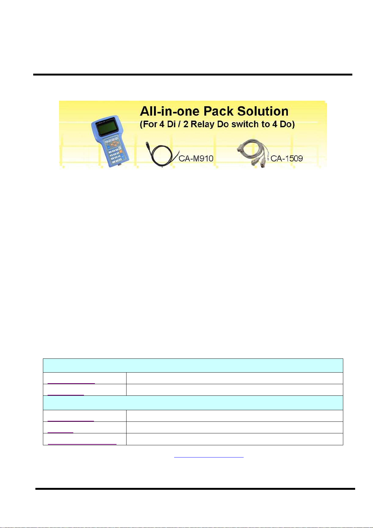
The all-in-one pack of iVIEW-100 series includes the following items:
One iVIEW-100 series handheld controller
One CA-M910 cable with 4 Di / 2 relay Do
One CA-1509 cable with one RS-232 port, one RS-232/485 port, and
one power connect line
One user’s manual (this manual)
One utility CD with Software drivers, demo programs & User’s Manual
Note
If any of these items are missing or damaged, contact the local distributors for more
information. Save the shipping materials and cartons in case you want to ship in the
future.
It is recommended to read README.TXT first. The README.TXT is given in the
CD\README.TXT. Some important information are provided in CD\README.TXT.
Ordering Information
iVIEW-100 Series Handheld Controller
iVIEW-100-40 CPU: 40MHz, Flash: 512k, SRAM: 512k
iVIEW-100 CPU: 20MHz, Flash: 512k, SRAM: 512k
Optional Accessories for iVIEW-100
S-512 / S-256 512/256K battery backup SRAM Module
DP-640 24V / 1.7 A DIN-Rail mounting power supply
CA-1509 / CA-M910 cables for iVIEW-100 series
Call distributor or check web site: www.icpdas.com for more information.
iVIEW-100 Series user’s Manual, 2006, v2.0 ----- 7
Page 8

1.2 iVIEW-100 Series
The iVIEW-100 is a compact handheld controller with low cost / high performance
text/graphic LCD display, specially designed for industrial environment that requires
high reliability and PC-compatibility.
The iVIEW-100, an all-in-one pack controller, can work independently with its own CPU,
I/O Board, full keys Keypad, Text/Graphic LCD, inside buzzer and in-packed connecting
cables to monitor and control the Data Inputs and Outputs.
The iVIEW-100-40, the representation of iVIEW-100 series, is powered by an 80188-40
CPU with 512K bytes of SRAM and 512K bytes of flash memory, and built in MiniOS7,
RTC, NVSRAM and EEPROM. It supports optional battery backup memory for
retaining more data. There are 4 DI, 4 DO (or 2 relay), 2 COM for RS232 / RS485
communication.
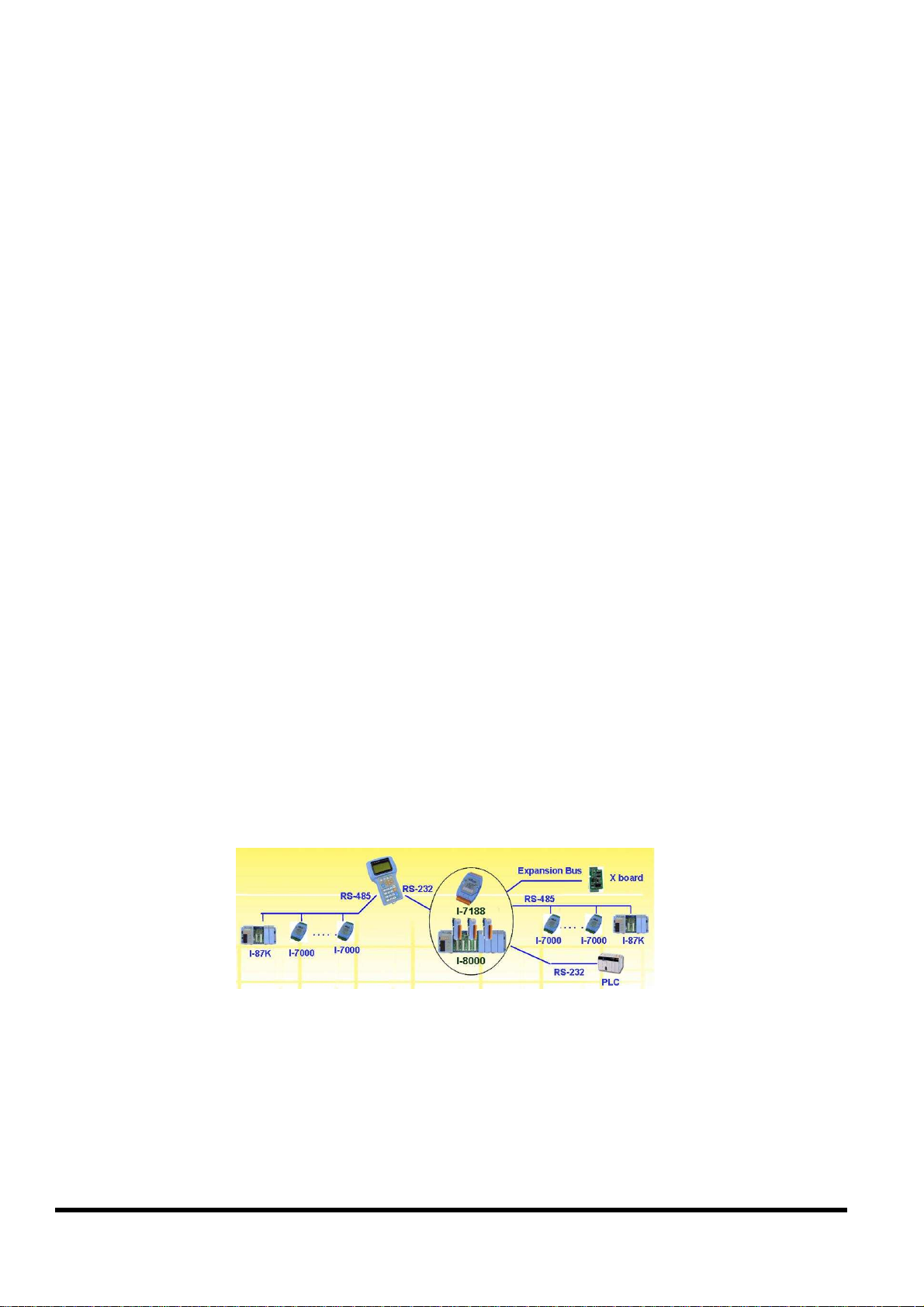
The iVIEW-100 can be also used as a HMI device for our I-7188 and I-8000 series
embedded controller. Since the basic hardware design of iVIEW-100 series is similar to
that of I-7188 series, all our available software can be used in iVIEW-100 series. User
can design iVIEW-100 application with C Language. We are porting ISaGRAF software
PLC to iVIEW-100-ISaGRAF for more programming options and providing iVIEW100E with a 10/100 mega Ethernet port for internet.
iVIEW-100 Series
iVIEW-100 Handheld Controller, CPU:20MHz, Flash:512k, SRAM:512k
iVIEW-100-40 Handheld Controller, CPU:40MHz, Flash:512k, SRAM:512k
iVIEW-100-ISaGRAF
iVIEW-100E
iVIEW-100E-ISaGRAF
Handheld Controller, CPU:40MHz, Flash:512k, SRAM:512k
with ISaGRAF software (available soon)
Handheld Controller, CPU:40MHz, Flash:512k, SRAM:512k
Ethernet port:10/100m (available soon)
Handheld Controller, CPU:40MHz, Flash:512k, SRAM:512k
Ethernet port:10/100m, with ISaGRAF software (available soon)
iVIEW-100 Series user’s Manual, 2006, v2.0 ----- 8
Page 9

1.3 Features
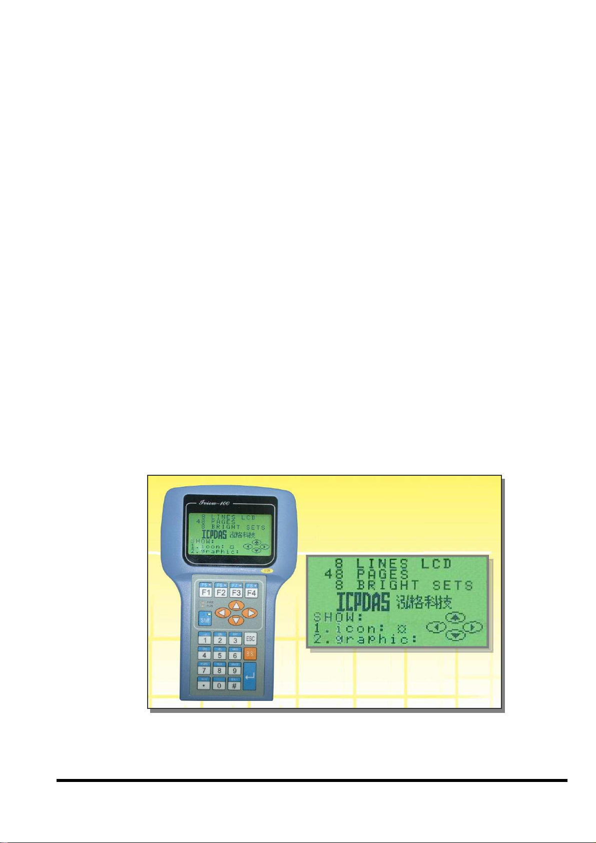
LCD display
Provides 128x64 dots, 16x8 characters, 72x40 mm view area, STN, Yellow-
Green Backlight LCD
Shows text, number, real, Boolean icon, BMP graphic in the same page
Draws pixel, line, box, Lamp icon
Max to 48 pages.
Membrane keypad
Full numeric membrane keypad with number, character, direction, shift, enter,
BS, ESC, function keys
Handheld controller
Embedded CPU, 80188, 40MHz(for iVIEW-100-40) or 20MHz(for iVIEW-100)
512K SRAM & 512K Flash ROM
MiniOS7 inside, support RTC time & date
Built-in RTC, NVSRAM & EEPROM
One buzzer inside
C programmable
64-bit hardware unique serial number
Equipped with a 64-bit unique hardware serial number, each serial number is
distinct and individual. The application program can check this number for
illegal copies. It is a low cost protection mechanism.
DI/O
Default has 4 digital inputs and 2 relay outputs connected with a Mini-DIN
connector (CA-M910).
Jumper selected to switch the output from 2 relay to 4 open collector output
channels via the internal jumper.
COM: RS232 & RS485
Built-in COM1:RS232, COM2:RS232/RS485 port, Max Speed up to 115200,
COM driver support interrupt & 1K QUEUE input buffer
iVIEW-100 Series user’s Manual, 2006, v2.0 ----- 9
Page 10
Allows C programming which can be downloaded from PC through COM1 via
its in packed cable (CA-1509).
Connects up to 64 numbers of remote I/O modules, and combines host PC, and
power supply via its CA-1509 cable with one 5-wire RS-232 port, one RS232/485 port, and one power connect line.
Real Time Clock
Supports Real time clock with time & date. RTC leap year compensation from
1980 to 2079.
Watchdog
Built-in watchdog timer for harsh environment. When iVIEW-100 is power-up,
the watchdog is enabled. It can reset the controller in 0.8 seconds.
Protection
Built-in power and RS-485 network protection circuit.
A wide temperature endurance ranged from -30℃ up to +85℃ for the storage
temperature, and from -25℃ up to +75℃ for operating temperature.
Application
Provides particular C programming Libraries so that user can easily call the
functions to design their applications, such as using LCD, keypad, R/W COM
port, EEPROM, RTC, I/O, FLASH memory, timer, watchdog, getting file
system & connecting to I-7000…
Provides several solutions combined with our I-7188 and I-8000 controller to
control more DI/O even with different protocol.
ODM project
Supports user adding battery backup memory (S-256/ S-512) to retain more data.
Customized I/O Expansion Boards can be ordered through ODM project for
user’s special need.
iVIEW-100 Series user’s Manual, 2006, v2.0 ----- 10
Page 11

1.4 Specifications
ic membrane keypad with number, character, direction, shift, enter, BS, ESC,
upports compilers TC 1.0~3.0/TC++ 1.0~3.0/BC 2.0/BC++ 3.1~5.02/MSC 8.00c/MSVC++
Power supply
Power requirements 10 to 30 VDC power, Consumption: 3.0 W
Protection Built-in power protection and RS-485 network protection circuit
General environment
Operating temperature -25°C to +75°C
Storage temperature -35°C to +85°C
Humidity 5 to 90 %
System
CPU 80188, iVIEW-100-40: 40M Hz, iVIEW-100: 20M Hz
SRAM 512K bytes
Flash Memory 512K bytes, Erase unit is 64K bytes, 100,000 erase/write cycles
OS MiniOS7 of ICP DAS (64K bytes)
NVSRAM 31 bytes, battery backup, data valid up to 10 years
EEPROM 2048 bytes, data retention > 100 years. 1,000,000 erase/write cycles
Real time clock Gives time(sec, min, hour) & date, leap year compensation from 1980 to 2079
Watchdog timer Yes,
Serial ports
COM1
COM2
Ethernet 10M/100M bps, provides in iVIEW-100E & iVIEW-100E-ISaGRAF only
DIO channel
Input 4 digital input channels for 3.5V~30V
Output
HMI interface
LCD display
Keypad
buzzer One internal buzzer
Development tool
C programming
Protocols
Remote I/O
User defined protocol User can write his own protocol applied at COM1, COM2
Battery backup SRAM
S-256 / S-512
Case
Dimensions 181mm X 116mm X 42mm
Weight 550g (375g when cables not included)
RS232 (5 pins): TXD,RXD,RTS,CTS,GND, Program download port.
Speed: 115200 bps max. Double buffer
RS232 (5 pins) / RS485 self-tuner, Speed: 115200 bps max.
RS232: TXD,RXD,RTS,CTS,GND, RS485: Data+, Data-
2 relay outputs (default) for contact rating: 30 VDC/ 1A to 125 VDC/ 0.5A or
4 open collector outputs (jumper selected) for 30V / 100mA maxi load / per channel
128x64dots, 16x8 character, text / BMP graphic, STN, yellow-green back light LCD, View
area: 72 X 40mm
Full numer
function keys
S
1.52. Provides C Lib functions for LCD, keypad, COM port, EEPROM, FLASH Memory,
timer, watchdog, I/O, NVRAM, RTC, getting file system, connecting to I-7000…
Program downloaded from PC via COM1
Supports I-7000 I/O modules & (I-87K base + I-87K serial I/O boards) as remote I/O.
Max. 64 remote I/O module for one controller
Supports S-256:256K bytes and S-512:512K bytes optional battery backup SRAM for
retaining data
iVIEW-100 Series user’s Manual, 2006, v2.0 ----- 11
Page 12

1.5 Contents of CD
You can find all the iVIEW-100 series driver, manual & data files in the folder of
CD\
Napdos\iVIEW100, or you can reach to our FTP web site to find newly released
information.
Web site: http://www.icpdas.com/download/iVIEW-100_series.htm.
CD :
MiniOS7: driver, demo programs, utility software
iVIEW-100 library files
Source code of demo programs
iVIEW-100 User’s Manual
References are given in ReadMe.txt in the CD
iVIEW-100 Series user’s Manual, 2006, v2.0 ----- 12
Page 13
Chapter 2. Hardware Information
2.1 View of iVIEW-100
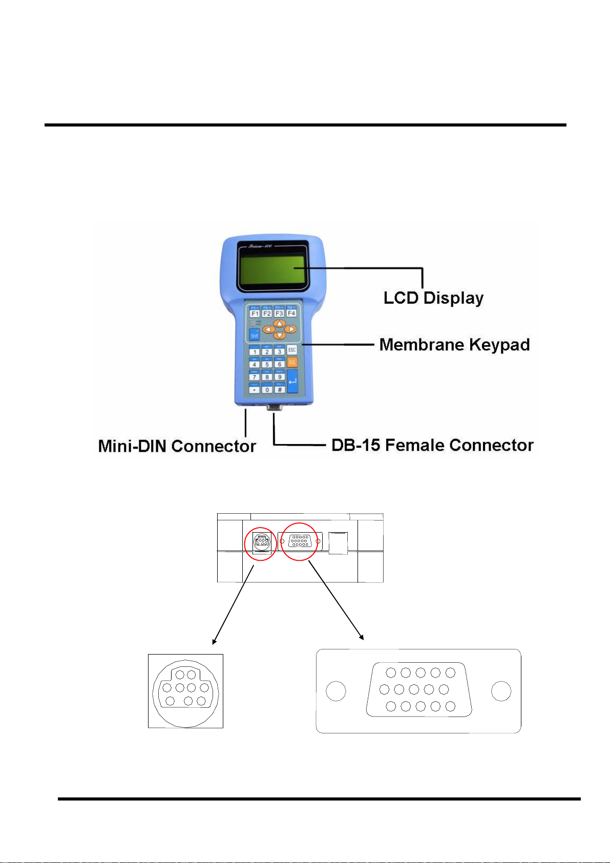
2.1.1 Front view
2.1.2 Bottom view
6
6
6
11
11
11
15
15
15
10
10
10
1
1
1
5
5
5
Mini-DIN Connector
iVIEW-100 Series user’s Manual, 2006, v2.0 ----- 13
DB-15 Female ConnectorMini-DIN Connector
DB-15 Female Connector
Page 14
(1)
(2)
(3)
(4)
(5)
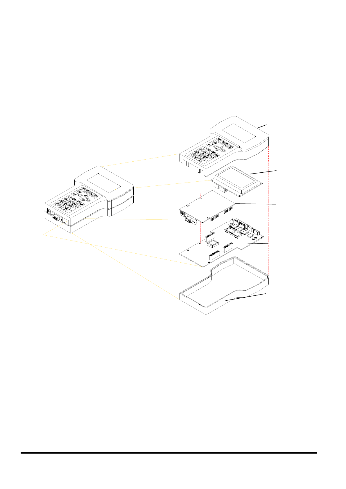
2.2 Expanded picture of iVIEW-100
iVIEW-
100
iViEW-100=
Upper CASE(1)+LCD(2)+I/O Board(3) + CPU Board(4) + Lower CASE(5)
iVIEW-100 Series user’s Manual, 2006, v2.0 ----- 14
Page 15
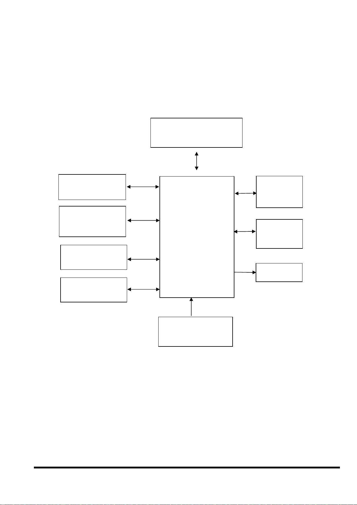
2.3 Block Diagram of iVIEW-100
COM1
RS-232
COM2
RS-232/RS-485
D/I,D/O
Circuitry
Membrane
Keypad
512K SRAM
512K Flash-ROM
80188-40
Watchdog timer
16 bits timer
RTC &
NVSRAM
EEPROM
(2K)
LCD
+10V to +30V
Power converter
iVIEW-100 Series user’s Manual, 2006, v2.0 ----- 15
Page 16
2.4 Pin assignment of iVIEW-100
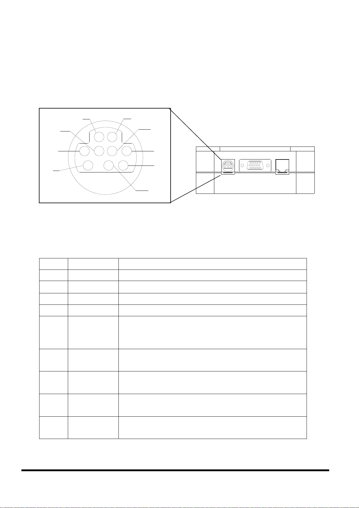
2.4.1 Pin assignment of Mini-DIN Connector
1
5
3
7
4
8
6
9
2
Mini-DIN Connector
Pin assignment of Mini-DIN connector:
Pin Name Description
1 DI1
2 DI2
Digital Input,3.5V~30V,channel1
Digital Input,3.5V~30V,channel2
3 DI3
4 DI4
5 DO PWR
Digital Input,3.5V~30V,channel3
Digital Input,3.5V~30V,channel4
Input Pin of external power supply for open
collector output
Note: no need for relay output
6 Relay1+
DO1
7 Relay1-
DO2
8 Relay2+
DO3
9 Relay2-
DO4
Relay 1 Output (default setting) N.O.
Digital Output 1 (jumper setting)
Relay 1 Output (default setting) N.O.
Digital Output 2 (jumper setting)
Relay 2 Output (default setting) N.O.
Digital Output 3 (jumper setting)
Relay 2 Output (default setting) N.O.
Digital Output 4 (jumper setting)
iVIEW-100 Series user’s Manual, 2006, v2.0 ----- 16
Page 17
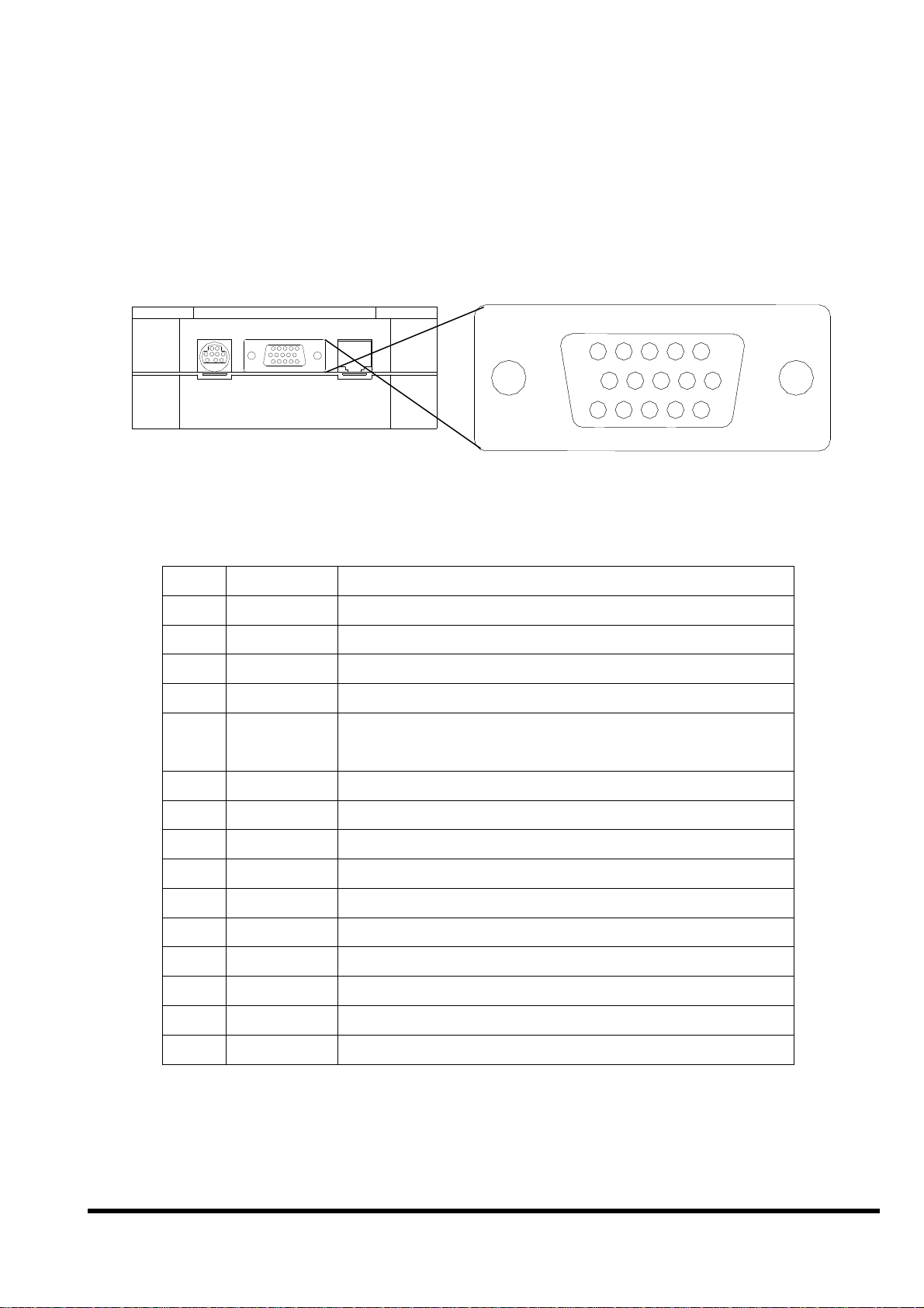
2.4.2 Pin assignment of DB-15 Female Connector
5
5
15
15
10
10
1
1
11
11
6
6
DB-15 Female Connector
Pin assignment of DB-15 Female Connector:
Pin Name Description
1 N/C
2 TXD1 TXD pin of COM1 (RS-232)
3 DATA+ DATA+ pin of COM2 (RS-485)
4 TXD2 TXD pin of COM2 (RS-232)
5 +VS V+ of power supply (+10 to +30VDC
unregulated)
6 INIT* Initial pin for ROM-DISK download
7 CTS1 CTS of COM1 (RS-232)
8 RTS1 RTS of COM1 (RS-232)
9 CTS2 CTS of COM2 (RS-232)
10 RTS2 RTS of COM2 (RS-232)
11 GND GND of power supply and COM1
12 RXD1 RXD pin of COM1 (RS-232)
13 DATA- DATA- pin of COM2 (RS-485)
14 RXD2 RXD pin of COM2 (RS-232)
15 GND GND of COM2
Note 1: COM1 ( DB-9 Female connector of CA-1518A)
Note 2: COM2 ( DB-9 Male connector of CA-1518A)
iVIEW-100 Series user’s Manual, 2006, v2.0 ----- 17
Page 18
2.5 Pin assignment of cables
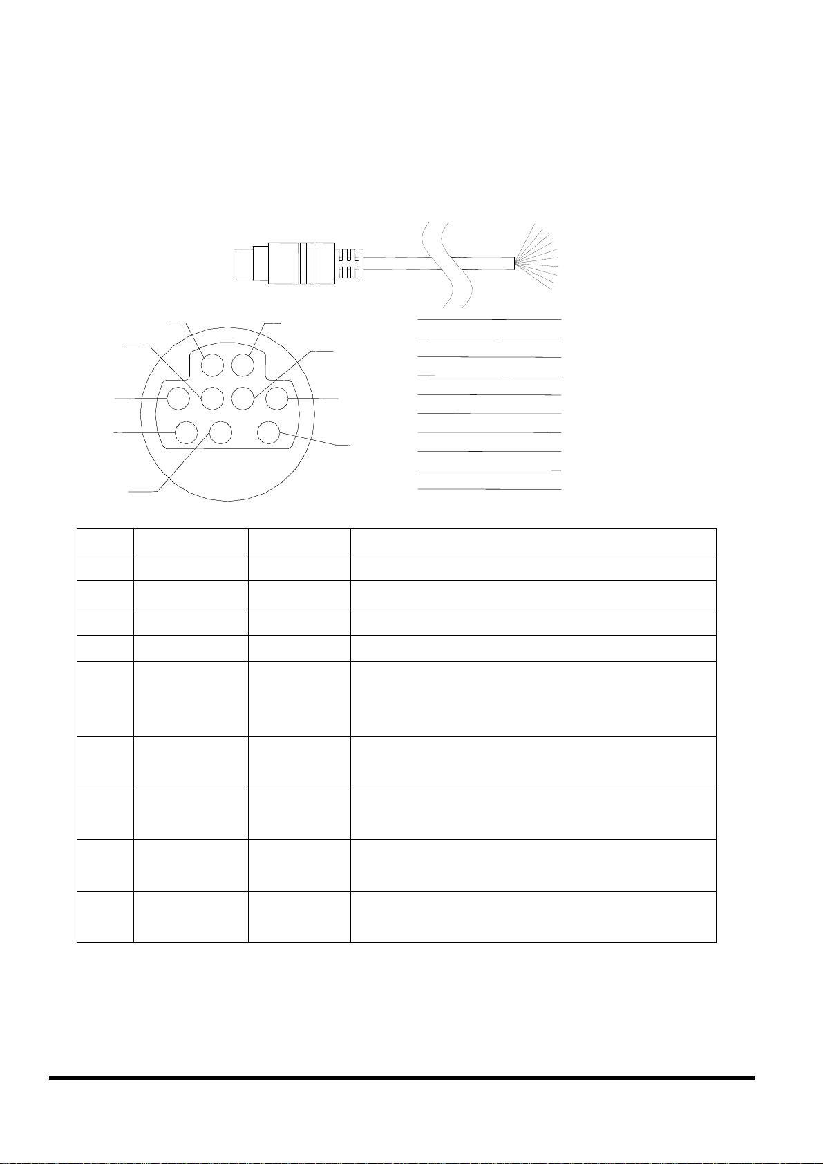
2.5.1 Pin assignment of CA-M910 cable
1
1
2
2
3
3
4
4
5
5
6
6
7
7
8
8
9
9
10
10
1
1
5
5
3
3
7
7
4
4
2
2
8
8
6
6
9
9
White
White
Gray
Gray
Yellow
Yellow
Brown
Brown
Green
Green
Black
Black
Light Blue
Light Blue
Red
Red
Blue
Blue
Cable Shelding
Cable Shelding
Shielding
Pin Name Color Description
1
2 DI2 Gray
3 DI3 Yellow
4 DI4 Brown
5 DO PWR Green
6 Relay1+
7 Relay18 Relay2+
9 Relay2-
DI1 White
Black
DO1
Light
DO2
Blue
Red
DO3
Blue
DO4
Digital Input,3.5V~30V,channel1
Digital Input,3.5V~30V,channel2
Digital Input,3.5V~30V,channel3
Digital Input,3.5V~30V,channel4
Input Pin of external power supply for
open collector output
Note: no need for relay output
Relay 1 Output (default setting) N.O.
Digital Output 1 (jumper setting)
Relay 1 Output (default setting) N.O.
Digital Output 2 (jumper setting)
Relay 2 Output (default setting) N.O.
Digital Output 3 (jumper setting)
Relay 2 Output (default setting) N.O.
Digital Output 4 (jumper setting)
Wiring:
Signal Ground: All digital inputs and outputs (except relay
outputs) signal grounds are the same as the grounds of power
used by the module.
iVIEW-100 Series user’s Manual, 2006, v2.0 ----- 18
Page 19
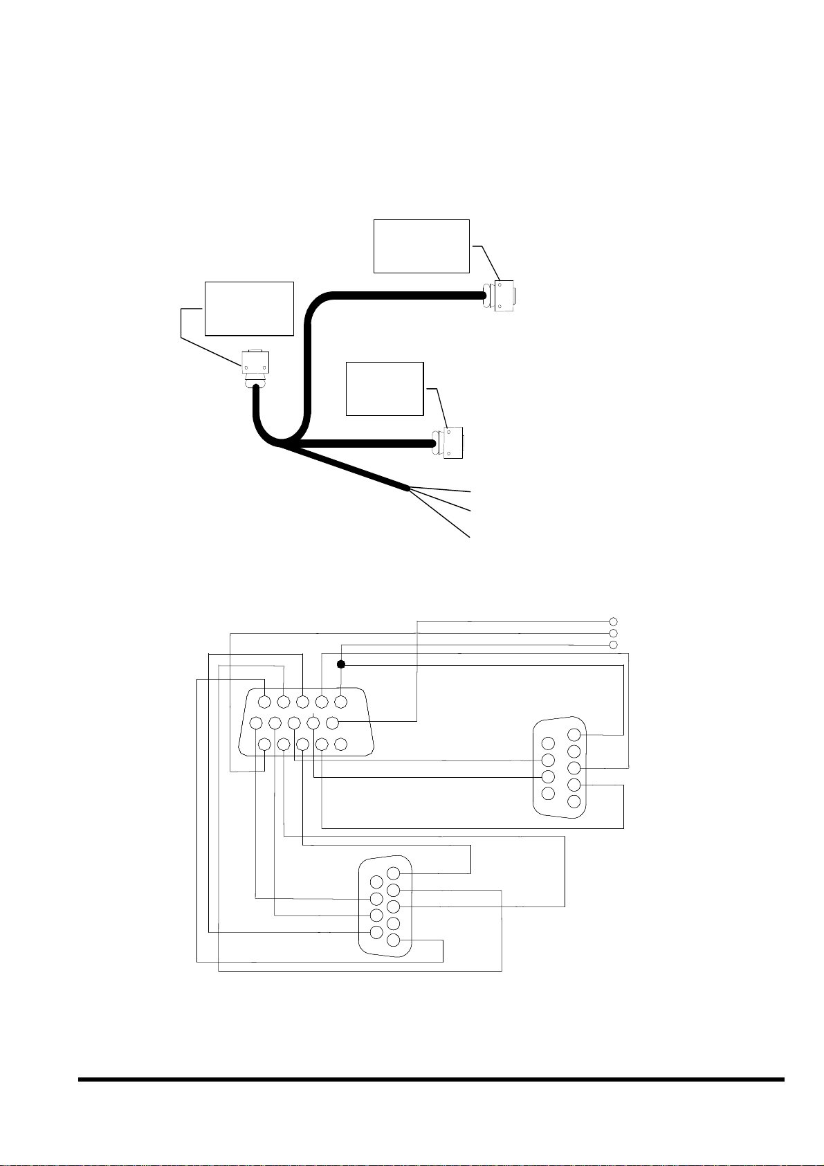
2.5.2 Pin assignment of CA-1509 cable
CA-1509 cable
Connect to
iVIEW-100
DB-9 Female
Connector
DB-15 Male
Connector
DB15-Male
DB15-Male
DB-9 Male
Connector
Com1:RS232
Connect to host-PC
Com2:RS232/RS485
Red (24V+)
Black (24V-)
White (*Init)
INIT *
INIT *
24V+
24V+
24C-
24C-
1314
1314
1314
1314
1112
1112
1112
15
15
15
15
89
89
89
89
10
10
10
10
5
5
5
5
RTS2
RTS2
CTS2
CTS2
DATA-
DATA-
1112
67
67
67
67
12
12
12
12
34
34
34
34
DATA+
DATA+
1
1
1
6
6
6
2
2
2
7
7
7
3
3
3
8
8
8
4
4
4
GND
GND
9
9
9
5
5
5
DB9-Male
DB9-Male
(COM2)
(COM2)
RTS1
RTS1
CTS1
CTS1
RXD2
RXD2
TXD1
TXD1
GND
GND
5
5
5
9
9
9
4
4
4
RXD1
RXD1
8
8
8
3
3
3
7
7
7
TXD1
TXD1
2
2
2
6
6
6
1
1
1
DB9-Female
DB9-Female
(COM1)
(COM1)
iVIEW-100 Series user’s Manual, 2006, v2.0 ----- 19
Page 20
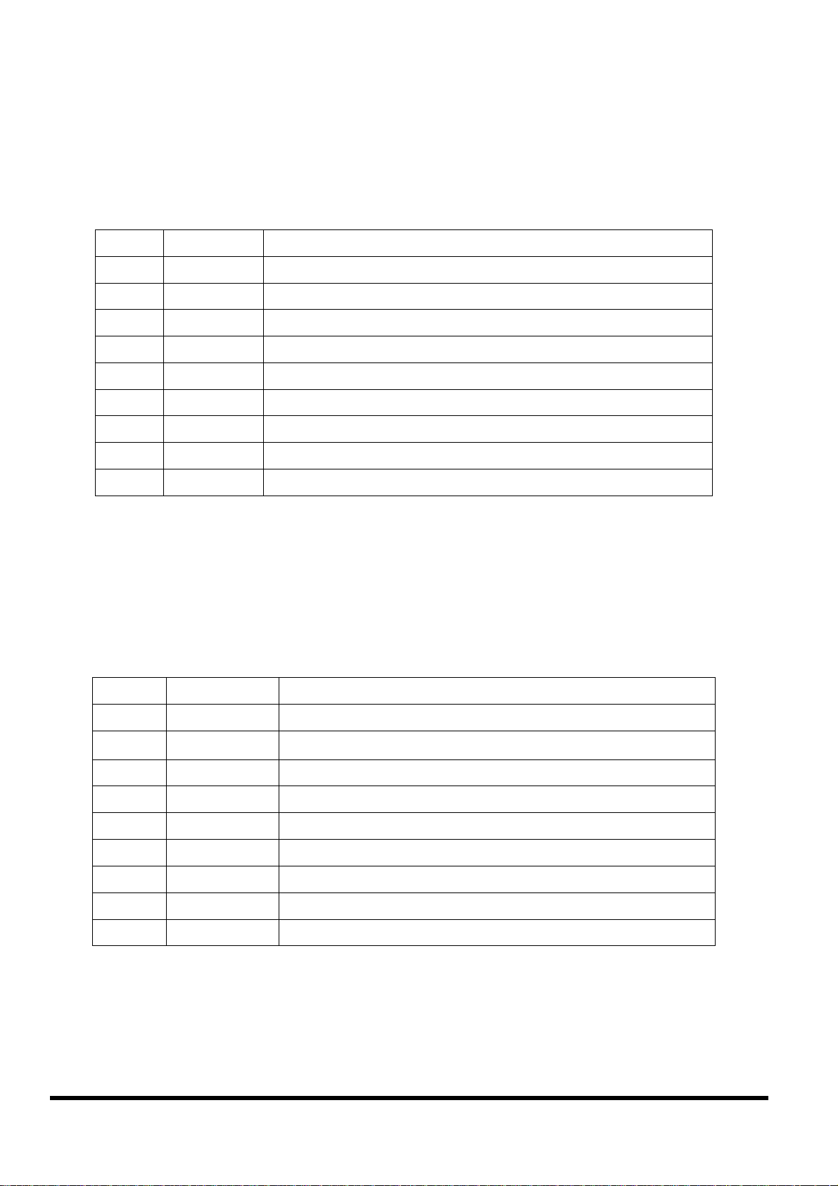
Pin assignment of COM1 connector (DB-9 Female connector of
CA-1509):
Pin Name Description
1 N/C
2 TXD Transmit Data
3 RXD Receive Data
4 N/C
5 GND Signal ground
6 N/C
7 CTS Clear To Send
8 RTS Request To Send
9 N/C
Pin assignment of COM2 connector (DB-9 Male connector of CA-
1509):
Pin Name Description
1 DATA+ DATA+ pin
2 RXD Receive Data
3 TXD Transmit Data
4 N/C
5 GND Signal ground
6 N/C
7 RTS Request To Send
8 CTS Clear To Send
9 DATA+ DATA- pin
iVIEW-100 Series user’s Manual, 2006, v2.0 ----- 20
Page 21
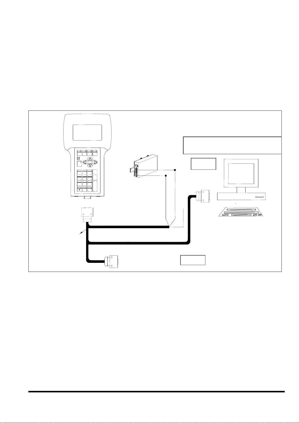
2.6 Wiring diagrams for application
2.6.1 Connecting the COM1 (DB-9 Female connector of
CA-1509) of iVIEW-100 to PC
Download Application Program
Download Application Program
from PC to iVIEW-100
F1
F1
F1
F1
PWR
PWR
PWR
PWR
RUN
RUN
RUN
RUN
Shift
Shift
Shift
Shift
1
1
1
1
GHI2JKL
GHI2JKL
GHI2JKL
GHI2JKL
4
4
4
4
PQRS
PQRS
PQRS
PQRS
7
7
7
7
+ - * /
+ - * /
+ - * /
+ - * /
F2
ABC
ABC
ABC
ABC
TUV9WXYZ
TUV9WXYZ
TUV9WXYZ
TUV9WXYZ
8
8
8
8
0 #
0 #
0 #
0 #
F8F5
F7F6
F8F5
F7F6
F8F5
F7F6
F8F5
F7F6
F4
F3F2
F4
F3F2
F4
F3
F4
F3F2
DEF
DEF
DEF
DEF
ESC
ESC
ESC
ESC
3
3
3
3
MNO
MNO
MNO
MNO
B.S.
B.S.
B.S.
B.S.
65
65
65
65
POWER SUPPLY
POWER SUPPLY
POWER SUPPLY
$ % ~
$ % ~
$ % ~
$ % ~
8
8
8
8
POWER SUPPLY
+10V~+30VDC
+10V~+30VDC
+10V~+30VDC
+10V~+30VDC
DB-9 Female
DB-9 Female
DB-9 Female
DB-9 Female
from PC to iVIEW-100
COM1
Connctor
Connctor
Connctor
Connctor
DB-15 Male Connector
DB-15 Male Connector
DB-15 Male Connector
DB-15 Male Connector
COM1/2 of
COM1/2 of
COM1/2 of
COM1/2 of
HOST COMPUTER
HOST COMPUTER
CA-1509
CA-1509
CA-1509
CA-1509
DB-9 Male Connector
DB-9 Male Connector
DB-9 Male Connector
DB-9 Male Connector
COM2
HOST COMPUTERHOST COMPUTER
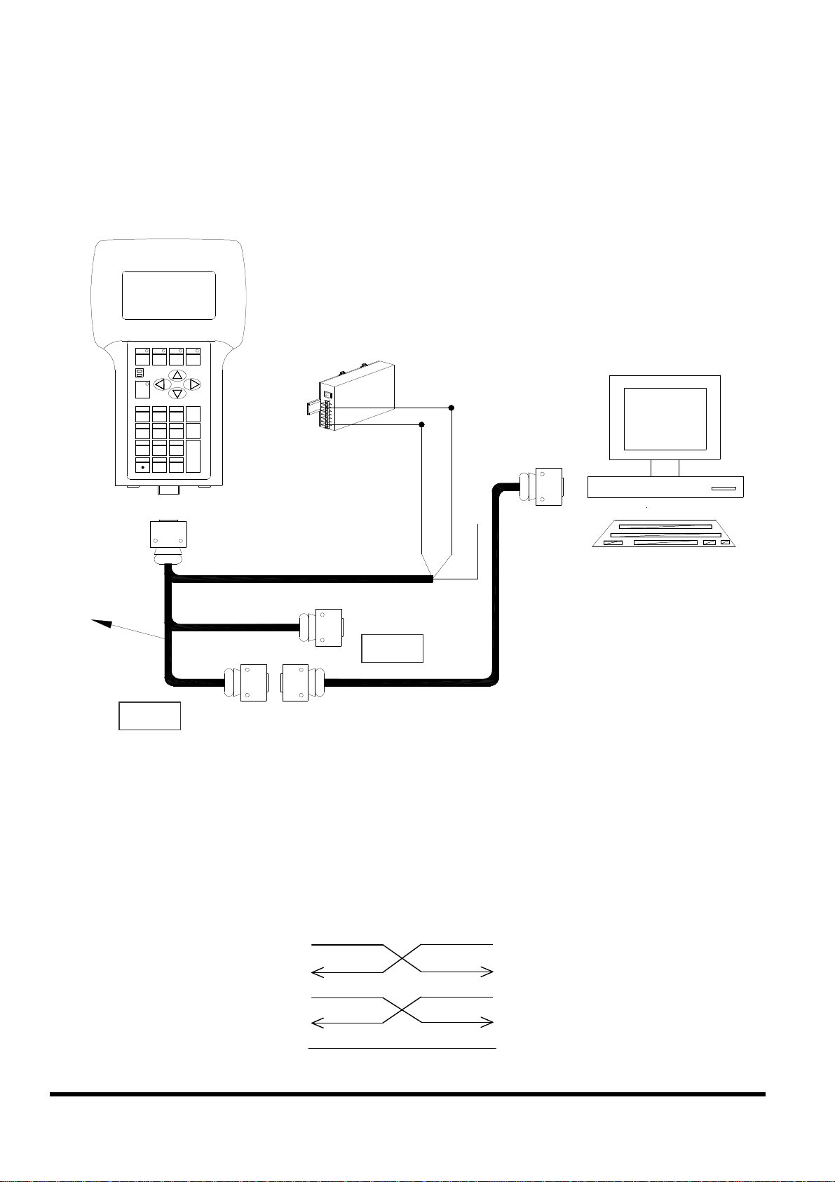
Note:
The CA-1509 cable has a female DB-9 connector, a male DB-9 connector,
and a power cable.
The iVIEW-100 needs external power via power cable.
Refer to Sec.2.5 for more information about the pin assignment of cable.
Connect the female DB-9 connector to COM1/2 port of PC for downloading
an application program from PC.
iVIEW-100 Series user’s Manual, 2006, v2.0 ----- 21
Page 22
2.6.2 Connecting COM2 (DB-9 Male connector of CA-1509)
CA-1509
to PC
F8F5
F7F6
F1
Shift
1
GHI2JKL
4
PQRS
7
+ - * /
PWR
RUN
F4
F3F2
ABC
DEF
ESC
3
MNO
B.S.
65
TUV9WXYZ
8
$ % ~
0 #
DB-15 Male
Connector
POWER SUPPLY
+10V~+30VDC
DB-9 Female
Connector
COM1/2 of
CA-1518A
DB-15 Female
DB-9
HOST COMPUTER
Connector
COM1
COM2
DB-9 Male
Connector
DB-9 Female
DB-9DB-9
Connector
Note:
The CA-1509 cable has a female connector, a male DB-9 connector, and a
power cable.
The iVIEW-100 needs external power via power cable.
Refer to Sec.2.5 for more information about the pin-assignment of cable
Using a female-to-female cable as a bridge between PC and COM2 of CA-
1509, the lines of communication are as follows:
TxD(3)
RxD(2)
DTR(4)
TxD(3)
RxD(2)
DTR(4)
DSR(6)
GND(5)
iVIEW-100 Series user’s Manual, 2006, v2.0 ----- 22
DSR(6)
GND(5)
Page 23
2.6.3 Connect COM2 (DB-9 Male connector of CA-1509)
CA-1509
to the COM1 Port of I-8000 series
F8F5
F7F6
PWR
RUN
ABC
TUV9WXYZ
8
0 #
F4
F3F2
DEF
ESC
3
MNO
B.S.
65
$ % ~
DB15 Male
Connector
POWER SUPPLY
+10V~+30VDC
841X/881X
DB9 Female
Connector
COM1(RS-232)
of 8000 series
F1
Shift
1
GHI2JKL
4
PQRS
7
+ - * /
CA-1518A
DB15 Female
DB-9
Connector
COM1
COM2
DB-9
Connector
DB9 Female
DB-9
Connector
DB9 Male
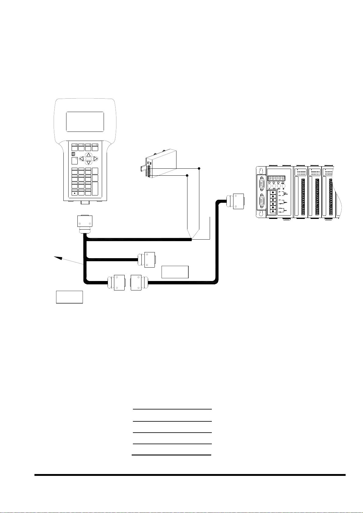
Note:
The CA-1509 cable has a female DB-9 connector, a male DB-9 connector,
and a power cable.
The iVIEW-100 needs external power via power cable.
Refer to Sec.2.5 for more information about the pin-assignment of cable.
Using a female-to-female cable as a bridge between 8000 series’
COM1 port and COM2 of CA1509, the lines of communication are
as follows:
TxD(3)
RxD(2)
TxD(3)
RxD(2)
DTR(4)
DSR(6)
GND(5)
iVIEW-100 Series user’s Manual, 2006, v2.0 ----- 23
DTR(4)
DSR(6)
GND(5)
Page 24
2.6.4 Connecting COM1 (DB-9 Female connector of CA-
CA-1509
1509) to RS-232 Device
F8F5
F7F6
F1
PWR
RUN
Shift
1
GHI2JKL
4
PQRS
7
+ - * /
F4
F3F2
ABC
DEF
ESC
3
MNO
B.S.
65
TUV9WXYZ
8
$ % ~
0 #
DB-15 Male
Connector
POWER SUPPLY
+10V~+30VDC
DB-9 Female
Connector
COM1
RS-232
DEVICE
CA-1518A
DB-9 Male
Connector
COM2
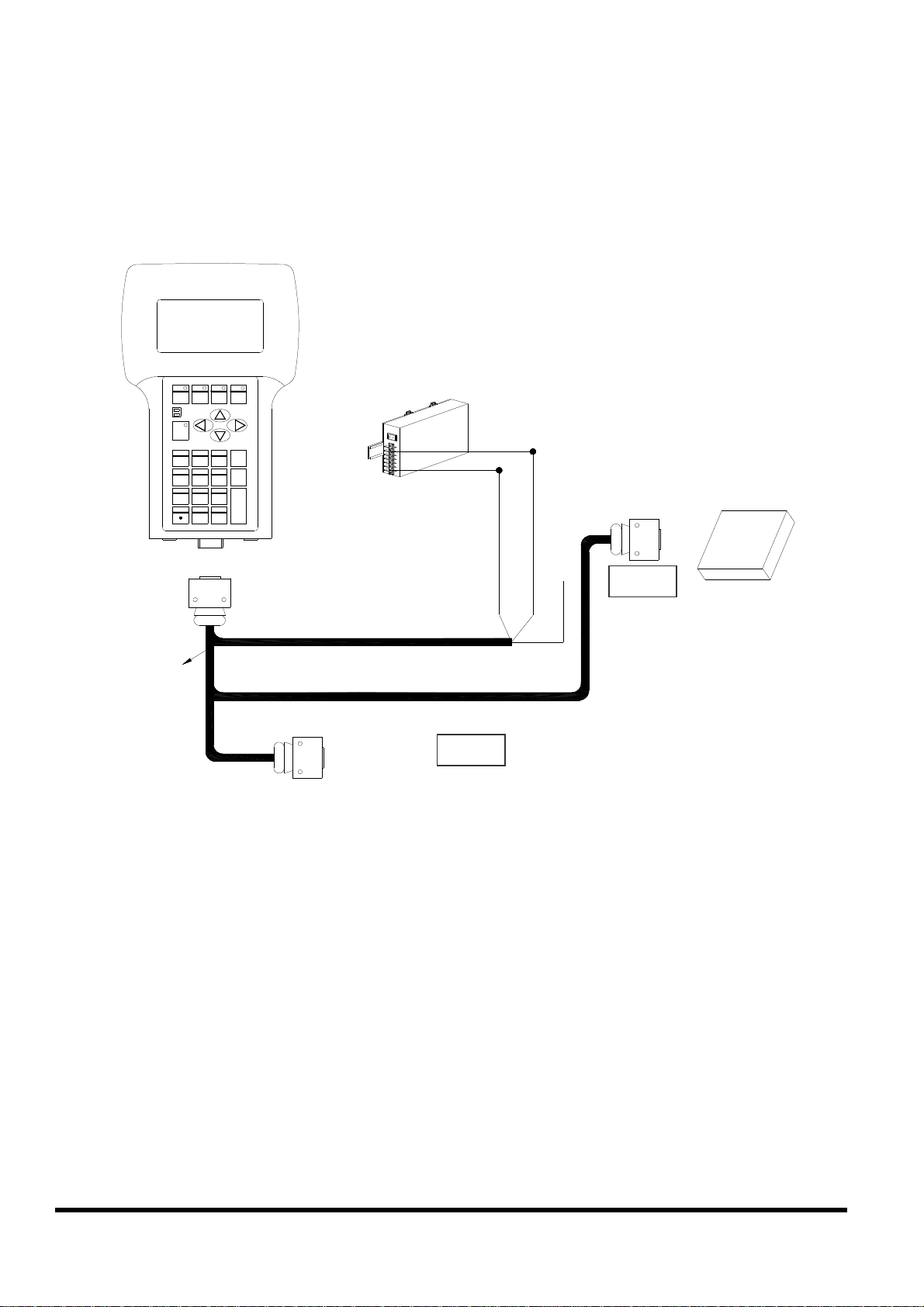
Note:
The CA-1509 cable has a female DB-9 connector, a male DB-9 connector,
and a power cable.
The iVIEW-100 needs external power via power cable.
Refer to Sec.2.5 for more information about the pin assignment of cable.
Connect the DB-9 Female to COM port of RS-232 devices
iVIEW-100 Series user’s Manual, 2006, v2.0 ----- 24
Page 25
2.6.5
CA-1509
Device
Connect COM2 (DB-9 Male of CA-1509) to RS-232
F8F 5
F7F6
F1
PWR
RUN
Shift
1
GHI2JKL
4
PQRS
7
+ - * /
F4
F3F2
ABC
DEF
ESC
3
MNO
B.S.
65
TUV9WXYZ
8
$ % ~
0 #
DB-15 Male
Connector
POWER SUPPLY
+10V~+30VDC
DB-9 Female
Connector
RS-232
DEVICE
CA-1518A
COM1
DB-15 Female
DB-9
Connector
COM2
DB-9 Male
Connector
DB-9 Female
Connector
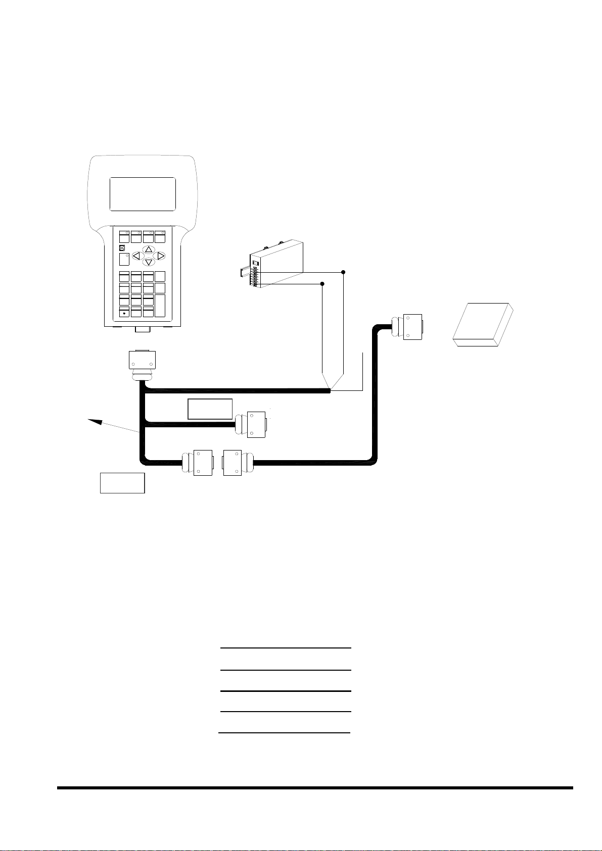
Note:
The CA-1509 cable has a female DB-9 connector, a male DB-9 connector,
and a power cable.
The iVIEW-100 needs external power via power cable.
Refer to Sec.2.5 for more information about the pin assignment of cable.
Using a female-to-female cable as a bridge between RS-232 device’s COM
port and COM2 of CA-1509, the lines of communications are as follows:
TxD(3)
TxD(3)
RxD(2)
DTR(4)
DSR(6)
GND(5)
RxD(2)
DTR(4)
DSR(6)
GND(5)
iVIEW-100 Series user’s Manual, 2006, v2.0 ----- 25
Page 26
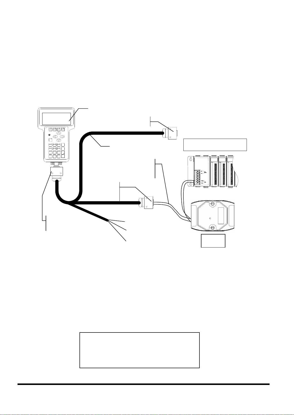
2.6.6
iVIEW
-
100
& 9
Connect COM2:RS-485 (DB-9 Male of CA-1509) to
I-7000 & I-87K Remote I/O
DB-15 Male
DB-9 Female, COM1
CA-1509
iVIEW-100 Pin 1
to Data+ & Data-
DB-9 Male
COM2
Red(24V+)
I-87K Remote I/O
I-87K4
Black(24V-)
White(*Init)
I-7000
Note:
The CA-1509 cable has a female DB-9 connector, a male DB-9 connector,
and a power cable.
The iVIEW-100 needs external power via power cable.
Refer to Sec.2.5 for more information about the pin assignment of cable.
Connect iVIEW-100 Pin 1 & 9 to the Data+ & Data- of I-7000 or I-87K remote
I/O. The communication of lines is as follow:
iVIEW-100 I-7000 I-87K IO
Pin1 Data+ Data+
Pin9 Data- Data-
iVIEW-100 Series user’s Manual, 2006, v2.0 ----- 26
Page 27
2.7 DI/DO operating principle
The iVIEW-100 has 4 digital inputs and 4 digital outputs.
The 4 digital outputs can be configured as 2 relay outputs by pin
assignment. The default setting is relay type.
Here is the pin configuration:
8:9:Relay 2 output
1
2
6 8 5 3
9
4
7
6:7:Relay 1 output
5:VCC
4:DI4
3:DI3
2:DI2
1:DI1
If it is configured as a 4 digital outputs, pin configuration will be:
9:DO4
8:DO3
2
1
7:DO2
6:DO1
6 8 5 3
5:VCC
4: DI 4
9
4
7
3: DI 3
2: DI 2
1: DI 1
Wiring:
Signal Ground: All digital inputs and outputs (except relay outputs)
signal grounds are the same as the grounds of power used by the
module.
iVIEW-100 Series user’s Manual, 2006, v2.0 ----- 27
Page 28
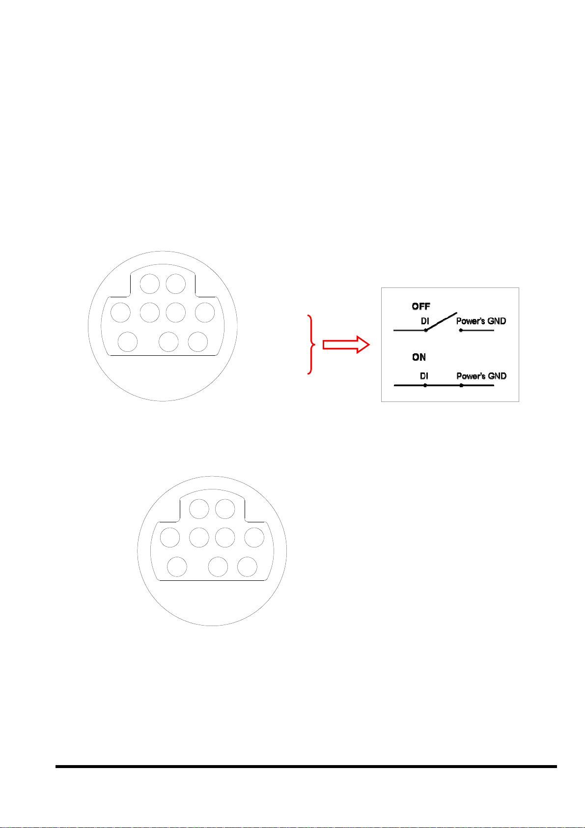
2.7.1 Digital inputs byte definition & wiring
DI byte definition is as follows:
Bit 8 Bit 7 Bit 6 Bit 5 Bit 4 Bit 3 Bit 2 Bit 1
DI2
DI3
DI4
Relay 1 output state
Relay 2 output state
Test7: signal from outport bit 7
Test8: signal from outport bit 8
Wiring:
DI1
Signal Ground: All digital inputs and outputs (except relay outputs)
signal grounds are the same as the grounds of power used by the
module.
iVIEW-100
+5V
DI
block diagram
If Pin 1,2,3, or 4 is float ( without connect any line), then input value is
“1”. If pin is connected to ground, the input value is “0”.
iVIEW-100 Series user’s Manual, 2006, v2.0 ----- 28
Page 29
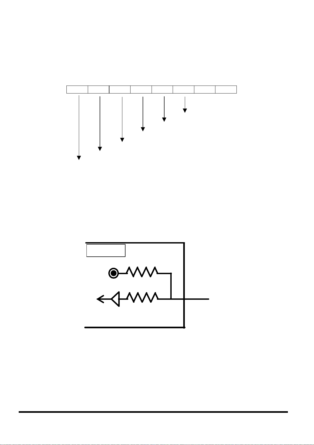
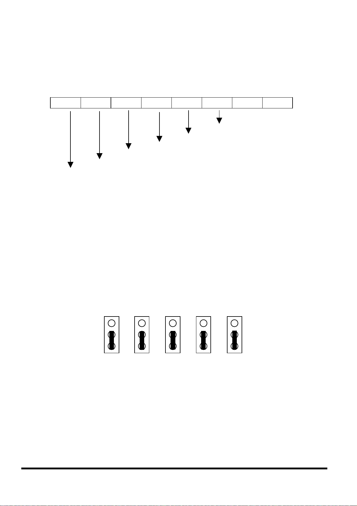
2.7.2 Digital output definition & wiring: 2 Relay Outputs
(default)
DO byte definition:
Bit 8 Bit 7 Bit 6 Bit 5 Bit 4 Bit 3 Bit 2 Bit 1
X
X
X
X
Relay 1
Relay 2
Test 7
Test 8
Wiring
N.O
iVIEW-100
relay 1
relay 2
block diagram
.
6
7
8
9
iVIEW-100 Series user’s Manual, 2006, v2.0 ----- 29
Page 30
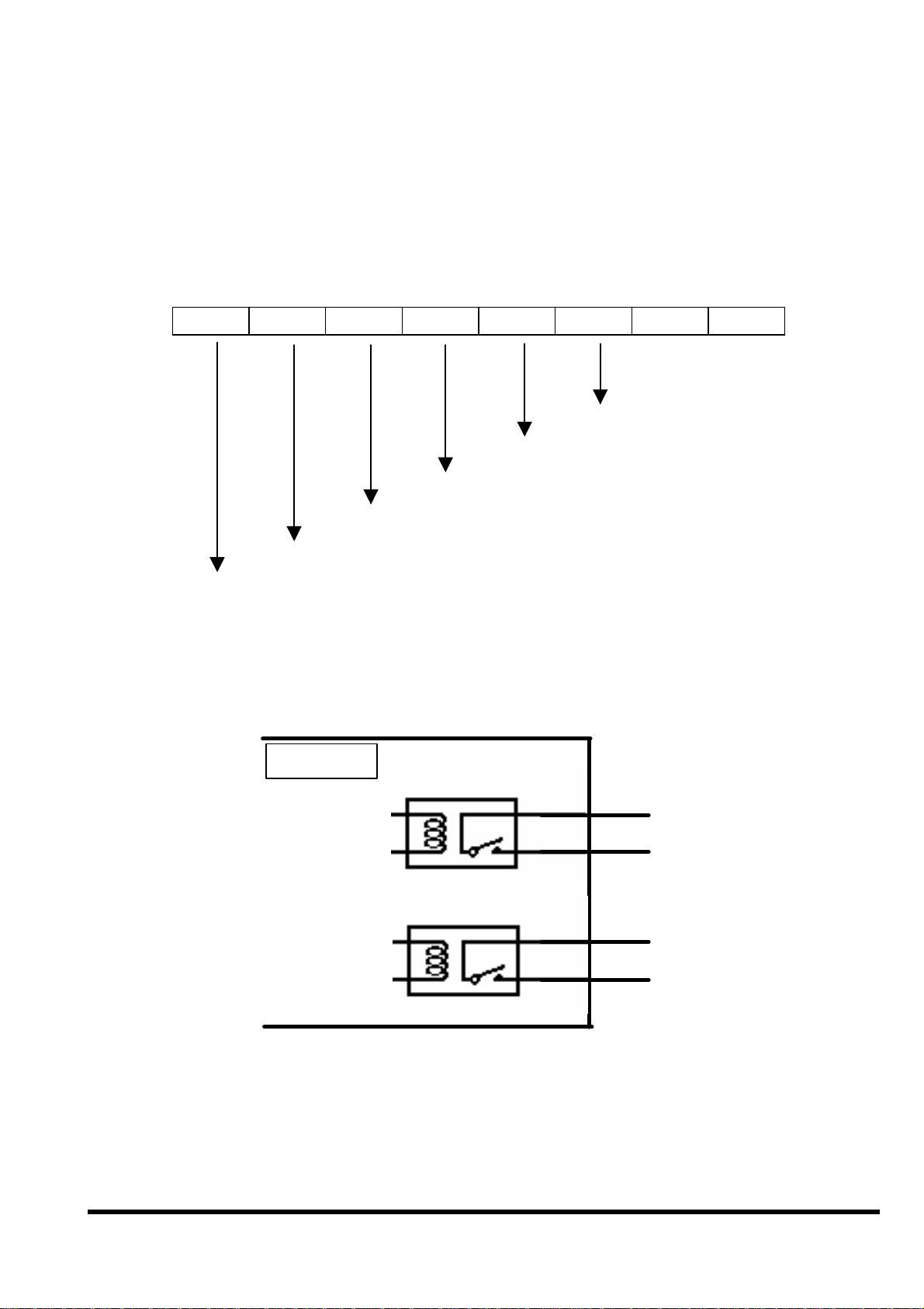
2.7.3 Digital output definition & wiring: 4 digital outputs
1
DO byte definition:
Bit 8 Bit 7 Bit 6 Bit 5 Bit 4 Bit 3 Bit 2 Bit 1
DO1
DO2
DO3
DO4
X
X
Test 7
Test 8
Wiring:
Signal Ground: All digital inputs and outputs (except relay output)
signal grounds are the same as the Power ground.
Jumper setting: This kind of DO needs to re-config jumper setting.
Please change jumper settings to the following (default setting is 1-2
short for relay output):
J12 J11 J10 J9 J8
iVIEW-100 Series user’s Manual, 2006, v2.0 ----- 30
Page 31

iVIEW-100
VCC
DO1
DO2
DO3
DO4
External power
suply
5
6
7
8
9
iVIEW-100 Series user’s Manual, 2006, v2.0 ----- 31
Page 32

2.7.4 DI/DO operating method
You can make commands in MiniOS7 Utility to test DI and DO. Please refer to
Chapter 3 & 4 (especially section 3.4 & 4.3) to see how to use MiniOS7 Utility.
The commands for testing DI & DO are listed below:
Type Command Description
DI i port Read data from the address of hardware port ( 0x104 )
DO o port value Output data value to the address of hardware port (0x105)
Ex1: Make command
Ex2: Make command
i 0x104
to get DI value as below.
Get value:
3F => 00111111 (DI4 => DI1 : 1111)
When DI changed, get value again:
76 => 01110110 (DI4 => DI1 : 0110)
If pin is float (without connect to any line), input value is “1”.
If pin is connected to ground, the input value is “0”.
o 0x105 DOvalue
Set value:
1F => 00011111 (Bit 8 => Bit 5 : 0001) (Relay 1 active)
Set value again, the DO will change:
2F => 00101111 (Bit 8 => Bit 5 : 0010) (Relay 2 active)
to set DO value as below.
The value will show the DI/DO byte value, please see the bits definition from
section 2.7.1 to 2.7.3.
iVIEW-100 Series user’s Manual, 2006, v2.0 ----- 32
Page 33

When user writes program for DI/DO, please use the following statements to get
or set DI/DO value.
For MSVC compiler:
int DI=_inp(0x104);
int DI=_inp(0x104) &0x0f; //to get Bit 1 to Bit 4 only
_outp(0x105, DOvalue); //DOvalue:0x1f, 0x2f, 0x3f… for 2 relay output
//DOvalue:0x01, 0x02, 0x04, 0x08… for 4 DO
For Turbo C or Turbo C++ compilers:
int DI=inportb(0x104);
int DI=inportb(0x104) &0x0f; /*to get Bit 1 to Bit 4 only*/
outportb(0x105, DOvalue);
/*DOvalue:0x1f, 0x2f, 0x3f… for 2 relay output*/
/*DOvalue:0x01, 0x02, 0x04, 0x08… for 4 DO*/
For more demo programs, please refer to demo files in the “COM” folder of CD :
dim.c, dom.c, do4o.c, dido.c …….
iVIEW-100 Series user’s Manual, 2006, v2.0 ----- 33
Page 34

2.8 I/O expansion bus & ODM project
The iVIEW-100 supports an I/O expansion bus. The I/O expansion bus
can be used to implement various I/O functions such as D/I, D/O, A/D,
D/A, Timer/Counter, UART, flash memory, battery backup SRAM,
AsicKey & other I/O functions. Nearly all kinds of I/O functions can be
implemented with this bus.
Users can design their own I/O expansion board for their expansion
bus. Each I/O expansion bus supports one expansion board only.
For convenience, if user has I/O expansion board requirement, please
contact us for ODM service. The I/O Expansion Boards can be ordered
through customized ODM project.
iVIEW-100 Series user’s Manual, 2006, v2.0 ----- 34
Page 35

2.9 Comparison Table
iVIEW-100-40 7188EX(D)
Module name
CPU
RAM
Flash ROM
Watch Dog CKT
RTC
EEPROM
Hardware Serial
number
I/O expansion
bus
COM1
COM2
Embedded Controller Internet Communication
Controller
80188, 40M 80188, 40M
512K 512K
512K 512K
Yes Yes
Yes Yes
2K bytes 2K bytes
Yes Yes
Yes Yes
RS-232 5-wire RS-232, 3-wire
RS-232 or
RS-485(non-isolated),
self-tuner ASIC inside
RS-485, non-isolated, self-
tuner ASIC inside
Ethernet 10M
OS
Program
No Yes
MiniOS7 MiniOS7
Yes Yes
Download
Display
7-Seg LED
LCD 7-Seg LED
No 5-digit for 7188EXD
iViEW-100: Embedded Controller
7188(D): Embedded Controller
7188XA/XB/XC (D): Expandable Controller
7521/22/23/25/27(D): Addressable Communication Controller
7188E1/2/3/4/5/8(D): Internet Communication Controller
7188E2X/EX/EA (D): Embedded Internet/Ethernet Controller
8000 Series: Compact Distributed Embedded Controller
7000 Series: Network Data Acquisition & Control Modules
iVIEW-100 Series user’s Manual, 2006, v2.0 ----- 35
Page 36

Chapter 3. Getting Start
Step 1: Connect to power supply & Host-PC.
Step 2: Insert companion CD & install the software.
Step 3: Download program to iVIEW-100.
Step 4: Execute program from PC.
Step 5: Execute program in iVIEW-100.
Step 6: Auto-execute program in iVIEW-100.
3.1 Connect to power supply & Host-PC
Step 1: Connect to power supply.
User can connect to his own power supply or optional order from both
our website and local agent. The DP-640 is a good choice for iVIEW-
100. You can also looking for the detail information to choose the
suitable power supply from our website:
http://www.icpdas.com/products/Accessories/power_supply/power_list.htm
DP-640
Step 2: Power off the iVIEW-100 from power supply.
Step 3: Connect INIT* to GND.
Step 4: Power on iVIEW-100 from power supply.
iVIEW-100 Series user’s Manual, 2006, v2.0 ----- 36
Page 37

F5
F2
F6
F3
F7
F4
F8
2
ESC
3
6
4
.
0 #
9
RUN
OM1 or
Step 5: Connect COM of PC to iVIEW-100.
iVIEW -100
PWR
F1
ABC
1
JKL
GHI
5
PQRS
TUV
7
8
+ - * /
DB-15 Male
Connector
DB-9 Female
PC
Connector
DEF
MNO
B.S.
WXYZ
$ % ~
CA-1509
Connector
Connect to C
COM2 of host-PC
DB-9 Male
Connector
Red(24V+)
Black(24V-)
White(*Init)
iVIEW-100 Series user’s Manual, 2006, v2.0 ----- 37
Page 38

3.2 Insert CD & install the software
Step: 1. Insert the companion CD. It will execute automatically.
Step: 2. Click Toolkits (Softwares) / Manuals
Step 3: Click iVIEW-100 Software & Libraries
iVIEW-100 Series user’s Manual, 2006, v2.0 ----- 38
Page 39

Step 4: Copy all directories and files to the working directory of your
disk driver. Or copy whole iVIEW100 directory to your disk.
Step 5: Install MiniOS7 Utility. Double click the install file in the folder of
minios7, follow the steps to install MiniOS7 Utility.
Note: The download utility, MiniOS7 Utility, is used as a bridge between iVIEW100 & Host-PC. It can be used in the Microsoft Windows environment for the
essential configuration and the programs download. The utility is similar to the
7188xw.exe(Windows console for Win32). Users can optional install the MiniOS7
utility or 7188xw.exe or both. Our manual will show the instruction and direction
via MiniOS7 Utility.
iVIEW-100 Series user’s Manual, 2006, v2.0 ----- 39
Page 40

3.3 Download program to iVIEW-100
Step 1: Execute MiniOS7 Utility. If you have not done the steps of 3.1,
follow the MiniOS7 Utility’s steps to connect iVIEW-100 to power
supply and Host-PC.
Step 2: Select the COM port that connected with Host-PC and the
Baud rate.
The iVIEW-100 use COM1 to download program from PC. The default
Baud rate of iVIEW-100 is 115200.
iVIEW-100 Series user’s Manual, 2006, v2.0 ----- 40
Page 41

Step 3: The left ListView show the files in the Host-PC. The right
ListView show the files in the iVIEW-100. Select disk name from the
Disk-Directory ComboBox. Select the folder and file from the left ListView below
the Disk-Directory ComboBox.
Example: C:\iview100\iviewapp\hello\
iVIEW-100 Series user’s Manual, 2006, v2.0 ----- 41
Page 42

Step 4: After choose a file from PC, click to download the file to iVIEW-100.
When finish the access, the file will be shown in the right ListView.
Example: C:\iview100\iviewapp\hello\hello.exe
iVIEW-100 Series user’s Manual, 2006, v2.0 ----- 42
Page 43

3.4 Execute program from PC.
Step 1: Double click the file name in the right ListView or select the file and then
click the icon to run the program.
hello
User can also type the command in the MiniOS7 command line to access the
program and see the result at the bottom of the window.
Example: type hello, then press the Enter key to access the program. In this
example, you can see the PC screen and the LCD of iVIEW-100 both show the
word “Hello”.
iVIEW-100 Series user’s Manual, 2006, v2.0 ----- 43
Page 44

iVIEW
-
100’s user functions.
I
nitial iVIEW libaries.
print
“
LCD wrong
”
on PC.
top spot.
Here is the content of Hello.c:
#include "iVIEW.H"
#include "mmi100.H"
int main()
{
InitLib();
Print("\n\rHello");
if(InitLCD()>0) Print("\n\rLCD wrong");
else
{
ClrScrn();
LcdPrintfAt(2,2,"Hello");
}
return 0;
}
Include these two headers to use
Print “Hello” on PC screen.
Initial iVIEW LCD, if fail,
Clear LCD screen first.
Print “Hello” on LCD (2,2).
iVIEW-100’s LCD is a 16
characters(X) wide, 8 lines(Y)
high screen. (1,1) is on the left
iVIEW-100 Series user’s Manual, 2006, v2.0 ----- 44
Page 45

If the program does not work or user wants to modify the program, after finish the
modification, downloads the file again. iVIEW-100 will keep all the files until user
deletes the files.
When user wants to delete the files in iVIEW-100, please clicks the icon
to delete all the files in iVIEW-100.
Note: MiniOS7 provide the function to
delete all
existing files only.
iVIEW-100 Series user’s Manual, 2006, v2.0 ----- 45
Page 46

3.5 Execute program in iVIEW-100
iVIEW-100 support user to run the program in the iVIEW-100 directly. iVIEW-100
has its own LCD display and full numeric membrane Keypad. After the program
downloaded from PC, iVIEW-100 can access the program independently. This
design makes the iVIEW-100 more suitable for harsh industrial environment.
Before we execute program in iVIEW-100, we will introduce the keypad usage of
iVIEW-100 to know how to use the keypad buttons to access the program.
3.5.1 Keypad usage
View of Keypad
iVIEW-100 Series user’s Manual, 2006, v2.0 ----- 46
Page 47

Usage of keypad for numbers and functions
Keys are designed to input various characters like a mobile phone.
Each key is divided into upper (blue) and lower (white) parts. The
number value is in white. The Alphabet is in blue. For example:
This key will be called Key “2” for convenience.
White part Blue part
F1 F5
F2 F6
F3 F7
F4 F8
1 ,.: (not print)
2 ABC
3 DEF
4 GHI
5 JKL
6 MNO
7 PQRS
8 TUV
9 WXYZ
. +-*/
0 [Space]
# $%~
Use “Shift” Key to shift between White part and Blue part.
iVIEW-100 Series user’s Manual, 2006, v2.0 ----- 47
Page 48

Here are some examples of number, Alphabet, or function key
inputs:
Example 1: Input “6”. This “character” is on the white part:
Step 1: Make sure that LED light on the ‘Shift’ key is off. If
on, press once to turn off.
Step 2: Press “6” key once, LCD will show “6”.
Example2: Input “S”. This letter is on the blue part of the “7” key of
your console.
Step 1: Press “Shift” key once to light-up the green LED on
the “Shift” button. If the LED is already on, there is no need
to press again.
iVIEW-100 Series user’s Manual, 2006, v2.0 ----- 48
Page 49

Step 2: Press “7” key. The red LED on the “F1” button lights.
Step 3: Press “7” key continously until the red LED of “F4”
lights. (Push 3 times more.)
Step 4: Press “F4” key or wait for 1 second to return “S” on
the LCD.
Step 5: Press “Shift” key. The green LED turns off. If you
want to input other characters from the blue block, don’t
press “Shift” key. Go to step 2.
iVIEW-100 Series user’s Manual, 2006, v2.0 ----- 49
Page 50

Example 3: Input “F1”. Press “F1” key directly to return it’s value(0x81).
Example 4: Input “F8”. This key is in the blue part of the “F4” key.
Step 1: Press “Shift” key to light-up the green LED of “Shift”
key.
Step 2: Press “F4” to return 0x88.
Step 3: Press “Shift” key to turns off the green LED.
Note: The LED on F1~F4 won’t light in this situation.
Example 5: input “space”(0x20). Press “Shift”. The green LED turns
on. Press “0” to return 0x20. Press “Shift”. The green LED
turn off.
iVIEW-100 Series user’s Manual, 2006, v2.0 ----- 50
Page 51

3.5.2 Download program and execute in iVIEW-100
Step: 1. Download the file \iview100\iviewapp\LCD\LCD.exe from PC
to iVIEW-100.
Step: 2. Use keypad key in “LCD” to run LCD program.
Press “Shift” key to light-up the green LED of “Shift” key.
Press 3 times of “5” key to return the letter “L” onto LCD.
Press 3 times of “2” key to return “C”, and 1 time of “3” key
to return “D”.
Press “Shift” key to turn off the green LED of “shift” key.
Then press “Enter” key.
The LCD display of iVIEW-100 will show the picture below, you can
press “1” or “2” to access this program.
CHOOSE:
1. LCD
2.
QUIT
iVIEW-100 Series user’s Manual, 2006, v2.0 ----- 51
Page 52

iVIEW
-
100’s user functions.
access this program.
Set LCD to page 2. From this line, the
LCD will store display to page 2.
C
lear LCD.
Call page 1 back as the main menu.
Here is the content of LCD.c:
#include <iVIEW.H>
#include <mmi100.H>
void main()
{
int quit=0;
char c;
InitLib();
InitLCD();
TextOutAt(5,3, "CHOOSE:");
TextOutAt(5,5, "1.LCD");
TextOutAt(5,6, "2.QUIT");
while(!quit)
{
c=Getch();
switch(c)
{
case '1':
Include these two headers to use
Initail libraries & iVIEW LCD.
Print “CHOOSE” on LCD (5,3),
“1.LCD” on (5,5), “2.QUIT” on (5,6)
from LCD left top. This menu display
is stored in page 1 by default.
Wait for key press to get char c. Both
iVIEW keypad and PC key board can
LCDSetToPage (2);
ClrScrn();
TextOutAt(3,4, "* welcome *");
TextOutAt(1,8, "any key to back");
Getch(); break;
case '2':
quit=1; break;
}
LCDSetToPage (1);
}
ClrScrn();
CloseLCD();
}
Print “welcome” message on LCD
(3,4) & (1,8). This is page 2.
iVIEW-100 Series user’s Manual, 2006, v2.0 ----- 52
Page 53

3.6 Auto-execute program in iVIEW-100
When developing software application, user can set the main program
to auto-execute when the iVIEW-100 is powered up. The method is the
same as in PC to set one autoexec.bat file.
Step 1: Set the autoexec.bat file.
Example: want to run LCD.exe menu when iVIEW-100 power
up.
The autoexec.bat file can just have one line include the file you
want to call or more commands or files to access. But this file
name has to be “autoexec.bat”.
The content of autoexec.bat: LCD.exe
Step 2: Download the autoexec.bat file to iVIEW-100.
Step 3: Power off iVIEW-100, then power on iVIEW-100 again. The
iVIEW-100 will execute autoexec.bat automatically and then
enter the main menu of LCD.exe.
CHOOSE:
3. LCD
4.
QUIT
iVIEW-100 Series user’s Manual, 2006, v2.0 ----- 53
Page 54

Chapter 4. Operating System - MiniOS7
The iVIEW-100 is a handheld controller with build-in MiniOS7 as its operating
system. The MiniOS7 is an embedded Operating System designed for the
iVIEW-100 series, I-7188/E/X series and I-8000 series. It is developed by ICP
DAS Co. Ltd.
Various companies have created several brands of DOS(Disk Operating System).
In all cases, DOS (whether PC-DOS, MS-DOS, or ROM-DOS) is a set of
commands or codes which tells the computer how to process information. DOS
runs programs, manages files, controls information processing, directs input and
output, and performs many other related functions. The MiniOS7 will provide
equivalent functions of ROM-DOS and provide some special functions.
4.1 Demo programs of MiniOS7
Program Description
Datetime
Reads the date and time of RTC per second and prints it on
monitor (user can set the date and time).Press ‘ q ’ to quit
program.
Demo6
Eeprom
Eeprom-r
Eeprom-w
Flash
Flash-r
Flash-w
Hello
Runprog
Scanf
Watchdog
More……
Writes, read and show the EEPROM data for checking.
Writes a value to EEPROM and show it on monitor.
Reads the data you wrote to EEPROM
Inputs a value to write to EEPROM block 1 peer address
(value will auto-plus 1).
Reads the value that is written to the flash memory.
Press ‘ q ’ to quit program.
Read, write and erases Flash memory.
Inputs a value written in flash memory (value will auto-plus 1.)
Press ‘ q ’ to quit program.
Prints “Hello” on both screen of PC and iVIEW-100
Uses Ungetch() to run another program.
Press ‘ q ’ to quit program.
Shows how to write a function for inputting data.
If system is reset by watchdog timer, then load this file and run it.
Refer to the Manual of MiniOS7 or our website…….
Refer to the
companion CD for the source code of demo programs.
iVIEW-100 Series user’s Manual, 2006, v2.0 ----- 54
Page 55

4.2 MiniOS7 Utility
The MiniOS7 utility is used for the essential configuration and program download
to the products embedded in the ICPDAS MiniOS7. The utility is similar to the
7188xw.exe (Windows console for Win32). However it can be used in the
Microsoft Windows environment, rather than a window console environment.
User can use MiniOS7 Utility to make command for MiniOS7. For larger screen
mode, click the icon for switching between the large and small screen modes
to see the result of the command.
iVIEW-100 Series user’s Manual, 2006, v2.0 ----- 55
Page 56

4.2.1 Make MiniOS7 command
To make MiniOS7 command, user just types command in the “MiniOS7
command Line” of MiniOS7 Utility.
Example 1: type “date” to show the current date of RTC. Type “date mm/dd/yyyy”
to set the date of RTC.
Example 2: type “baud 115200” to set the baud rate to 115200.
Example 3: type “dir” to show the information of all files downloaded in the Flash-
Memory.
Example 4: type “hello” to run hello.exe program or type “run” to run the last file.
iVIEW-100 Series user’s Manual, 2006, v2.0 ----- 56
Page 57

4.2.2 Toolbar and hot keys
Toolbar
There is one toolbar for MiniOS7 command line. It is at the left hand side of the
command line.
1. : ASCII/HEX mode switch icon.
2. : Normal mode and line key-in mode switch icon. In Line mode, all
3. : Run 7188xw.exe icon.
4. : Edit font icon. For changing the font, size and color of words in
characters-pressed will not send to COM until the ENTER is
pressed. It is designed for testing the 7000 series.
the screen.
5. : Edit color icon. For changing the color of screen.
Hot keys
You can click the right mouse on the screen to show the hot keys table.
iVIEW-100 Series user’s Manual, 2006, v2.0 ----- 57
Page 58

4.3 Typical commands of MiniOS7
Command Description
USE NVRAM
USE EEPROM
USE Flash
USE COM2 /option
DATE mm/dd/yyyy]
TIME [hh:mm:ss]
MCB
UPLOAD
BIOS1
LOAD
DIR [/crc]
RUN [fileno]
Name
DELETE (or DEL)
The service routine for read/write NVARM.
The service routine of read/write EEPROM.
The service routine of read/write Flash-ROM.
The service routine of send/receive to/from COM2 (RS-485).
Sets the date of RTC.
Sets the time of RTC.
Tests current memory block.
The first step to update the MiniOs7.
The last step to update the MiniOs7.
Downloads the user program into the Flash-Memory.
Shows the information of all files download in the FlashMemory.
Runs the file with file-number=fileno, no filenethe last file.
Runs the file with file-name=name.
Deletes all files stored in the Flash-Memory. It will delete all
files.
RESET
DIAG [option]
BAUD baudrate
TYPE filename [/b]
REP [/#] command
RESERVE [n]
LOADR
RUNR [param1
[param2...]]
I/INP/IW/INPW port
O/OUTP/OW/OUTP
W port value
… more …
Note: Refer to companion CD 8000CD\Napdos\7188e\MiniOS7\doc\index.html
for more information about MiniOS7. The MiniOS7 is also designed for 7188
/7188X/7188E/8000 family, so you will find some additional information unrelated
Resets the CPU.
Hardware Diagnostic.
Sets the new value of communication-baudrate to baudrate.
Lists content of the file.
Repeats executing the same command # times.
Reserves n Flash Memory sectors for USER's programs.
Downloads a file into SRAM.
Runs a program saved into SRAM (downloaded by command
LOADR).
Reads data from the hardware PORT.
Outputs to hardware PORT.
… more …
to iVIEW-100.
iVIEW-100 Series user’s Manual, 2006, v2.0 ----- 58
Page 59

4.4 Upgrade MiniOS7
We will add more & more features to upgrade the MiniOS7. Please refer to our
website to see if there any new version available.
The MiniOS7 Utility provides an easy way to upgrade MiniOS7.
Step 1: Please download the newest version of MiniOS7 file from
website if necessary. And then decompress to the image file.
The website is
Http://ftp.icpdas.com.tw/pub/cd/8000cd/napdos/minios7/.
The format of image file name is given as TTYYMMDD.img
TYPE of product
TT
“i4”=iVIEW-100-40, “i-“=iVIEW-100, “8k”=8000…
YY Year of this image released
MM Month of this image released
DD Day of this image released
Step 2: Execute the MiniOS7 Utility. Click the icon to update.
Step 4: After the update, it will auto reset. If not, please power off and
then power on
again. Use command “ver” to check on the new OS.
iVIEW-100 Series user’s Manual, 2006, v2.0 ----- 59
Page 60

4.5 7188xw.exe Utility
There is one more PC side utility program for MiniOS7--7188xw.exe. The
7188xw.exe is the Win32 Windows console programs for MiniOS7.
7188xw.exe supports RS-232 COM ports using USB and PCMCIA interfaces on
Win32 systems. It link to the modules via RS-232 port of PC to access MiniOS7.
7188xw.exe basically is a terminal program. It sends out the data that user key-in
to COM port, and show the data received from COM port on the screen of PC.
The main function for 7188xw.exe is to DOWNLOAD files to the MiniOS7 system.
In operating, Compare to MiniOS7 Utility, the 7188xw.exe has no any icon for
user to run functions. Users have to type MiniOS7 command by themselves to
access the MiniOS7.
For example, when download the program from PC to iVIEW-100, type “load”,
press “Enter”, after message, press “ALT_E”, and then type file full name, press
“Enter”. After those steps, the file will be downloaded from PC to iVIEW-100
memory. User can type the file name to run the file program.
iVIEW-100 Series user’s Manual, 2006, v2.0 ----- 60
Page 61

4.5.1 7188xw.exe commands & hot key
Command line options of 7188xw.exe for MiniOS7:
Option Description
/c# Uses PC's COM#
/b# Sets baud rate of PC’s COM port (default is 115200)
/s# Sets screen’s display-rows (default is 25, max. is 50)
Hot-key of 7188xw.exe:
Command Description
F1 Shows help messages of 7188xw.exe
Alt_F1 Shows the Chinese (Big5) help messages of 7188xw.exe
Ctrl_F1 Shows the Chinese (GB2312) help messages of
7188xw.exe
Alt_1 Uses PC's COM1
Alt_2 Uses PC's COM2
Alt_3 Uses PC's COM3
Alt_4 Uses PC's COM4
Alt_5 Uses PC's COM5
Alt_6 Uses PC's COM6
Alt_7 Uses PC's COM7
Alt_8 Uses PC's COM8
Alt_9 Uses PC's COM9
Alt_A Switches between normal mode and ANSI-Escape-code-
support mode
Alt_C Switches to command mode. Supports commands:
b#: Sets new baud rate of PC’s COM ports.
c#: Uses PC’s COM#.
n/e/o: sets parity to none/even/odd.
5/6/7/8: Sets data bits to 5/6/7/8.
p#: Sets PC’s working directory.
q: Quits command mode.
Alt_D Sets the date of RTC to the PC's date.
Alt_T Sets the time of RTC to the PC's time
iVIEW-100 Series user’s Manual, 2006, v2.0 ----- 61
Page 62

Alt_E For downloading files into memory. Only after the message
pressed will not send to COM until the ENTER is pressed. It
“Press ALT_E to download file!” is shown on screen, users
can press Alt_E.
Alt_H Toggles Hex/ASCII display mode.
Alt_L Toggles normal/line mode. In line-mode, all characters-
is designed for testing the 7000 series.
Alt_X Quits the 7188X.EXE.
F2 Sets the file name for download (without download
operation).
F5 Runs the program specified by F2 and arguments set by F6.
Alt_F5 Runs the program stored in SRAM.
F6 Sets the arguments of the execution file set by F2. (10
arguments maximum. If set to less than 10 arguments, add
‘*’ to end).
Ctrl_F6 Clears screen.
F8 F8=F9+F5.
F9 Downloads the file specified by F2 into FLASH memory.
Alt_F9 Downloads all files specified by ALT_F2 into FLASH
memory.
F10 Downloads the file specified by F2 into SRAM and execute
it.
Alt_F10 Downloads the file specified by F2 into SRAM memory.
Ctrl_B Sends a BREAK signal to the PC’s COM port that is used
by 7188xw.exe.
more … … more …
iVIEW-100 Series user’s Manual, 2006, v2.0 ----- 62
Page 63

Chapter 5. Libraries & compiler
User must use C language to develop the application program for
iVIEW-100-40 and iVIEW-100. We provide hundreds of functions in the
libraries for user to call for C programming.
When compile and link your programs, you can use
1.0~3.0, BC 2.0, BC++ 3.1~5.02, MSC 8.00c or MSVC++ 1.52.
TC 1.0~3.0, TC++
You can
download the freeware, TC 2.01 and the TC++ 1.01, from the website
of Borland company: http://community.borland.com/museum.
5.1 Libraries
There are two libraries for iVIEW-100-40 & iVIEW-100 programming:
(1) iVIEWL.lib
(2) mmi100.lib
: for normal functions program. (LARGE MODEL)
: specially for LCD display functions. (LARGE MODEL)
All the function declarations are described in iVIEW.h and mmi100.h. The
application program has to add “iVIEWL.lib” and “mmi100.lib” into the project to
implement the user functions, and include the following headers to the start of
the code.
#include "iVIEW.h"
#include "mmi100.h"
iVIEW-100 Series user’s Manual, 2006, v2.0 ----- 63
Page 64

5.1.1 iVIEWL.lib
ReadNVRAM, WriteNVRAM, GetTime, SetTime, GetDate,
There are hundreds of functions supported in iVIEWL.lib. You can see
all their declarations in iVIEW.h. Here will list the most frequently used
functions below.
No Type Function
1 Standard IO Kbhit, Getch, Ungetch, Putch, Puts, Scanf, Print,
ReadInitPin, LineInput….……... more ……………..
2 COM port InstallCom, InstallCom1, InstallCom2, InstallCom3……
RestallCom, RestallCom1, RestallCom2……
IsCom, IsCom1, IsCom2……, ReadCom, ReadCom1……
ClearCom, ClearCom1…, ToCom, ToCom1, ToCom2......
PrintCom, PrintCom1, PrintCom2…………more…………
3 EEPROM EnableEEP, WriteEEP, ProtectEEP, ReadEEP,
InitEEPROM...
4 NVRAM &
RTC
5 Flash Memory FlashReadId, FlashErase, FlashWrite, FlashRead………
6 Timer &
Watchdog
Timer
7 File GeFileNo, GetFileName, GetFilePositionByNo,
8 Connect to
7000
9 Others ……….………………..more …………………………..
SetDate, GetWeekDay……………
TimerOpen, TimerClose, TimerResetValue,
TimerReadValue
DelayMs, Delay, Dealy_1, Delay_2, StopWatchStart,
StopWatchReset, StopWatchStop, StopWatchPause,
StopWatchCountine, StopWatchReadValue,
CountDownTimerStart, CountDownTimerReadValue,
InstallUserTimer, InstallUserTimer1C
EnableWDT, DisableWDT, RefreshWDT…………
GetFileInfoByNo, GetFileInfoByName…………
SendCmdTo7000, ReceiveResponseFrom7000,
ascii_to_hex, hex_to_ascii……
Refer to CD\napdos\7188\minios7\manual\index.html for more detail description
and information.
For more detail description and demo programs information
please see the Appendix A: User function.
iVIEW-100 Series user’s Manual, 2006, v2.0 ----- 64
Page 65

5.1.2 LCD library: mmi100.lib
Please refer to mmi100.h to see the function declarations.
All the LCD demo programs are in the folder of LCD. For more detail
description and demo programs information please see the
Appendix A: User function.
Type
Function Description
initial & close
Draw & BMP
picture (pixel)
(X,Y) :
X=1~128
Y=1~64
Text & icon
(character)
(X,Y) :
X=1~16
Y=1~8
InitLCD Initial LCD in the beginning, return 0 for true
CloseLCD Close LCD when finish, return 0 for true
ClrScrn Clear all display in LCD
Pixel Give (X,Y) to draw a dot
VLine Give 1X, 2Y to draw a vertical line
HLine Give 2X, 1Y to draw a horizontal line
Line Give 2 points to draw a line
Box Give 2 points to draw a box
BmpShowAt Give a beginning point & a BMP filename to
show the BMP picture
UnderLine Give a begging point & length to print underline
TextOutAt Give (X,Y) to print char text
DrawText Give (X,Y) to print unsigned char text
LcdPrintfAt Give (X,Y) to print char text
IntOutAt Give (X,Y) & length to print integer number
RealOutAt Give (X,Y), length, decimal, float to print real
number
lamp
Give (X,Y) to print lamp icon, color: 1= , 0=
Cursor
(X,Y) :
X=1~16
Y=1~8
Page &
bright
SetCursorLine Set cursor’s thick from 0 to 8, 0=cursor off
SetCursorAt Set cursor to (X,Y)
GetCursorAt Get cursor position (X,Y)
LCDBright Set LCD bright from 0 to 7, 0=light off
LCDSetToPage Set LCD pages from 1 to 8, default=1
GetLCDPage Get LCD page set number
iVIEW-100 Series user’s Manual, 2006, v2.0 ----- 65
Page 66

5.2 Compiler & linker
When compile and link your programs, you can use
1.0~3.0, BC 2.0, BC++ 3.1~5.02, MSC 8.00c or MSVC++ 1.52.
TC 1.0~3.0, TC++
User can
download the freeware, TC 2.01 and the TC++ 1.01, from the website
of Borland company: http://community.borland.com/museum.
5.2.1 Special settings and libraries information
Please take care of the following items:
1. Generate a standard DOS executable program.
2. Select CPU=80188/80186
3. Select EMULATION if the floating-point computation is required. (Cannot
select 8087)
4. Remove DEBUG INFORMATION to reduce program size. (MiniOS7 does not
support it)
MiniOS7 provides some special libraries to replace standard I/Olibraries as following:
Standard I/O-library is replaced
MiniOS7 provided IO-library
by
getch Getch
kbhit Kbhit
putchar Putch
ungetch Ungetch
puts Puts
printf Print
scanf
Scanf
NOTE: We use '\n' in printf & puts for line changed displays. It
must be changed to '\n\r' or '\r\n' in the MiniOS7 environment.
iVIEW-100 Series user’s Manual, 2006, v2.0 ----- 66
Page 67

5.2.2 Using Turbo C
User can download Turbo C version 2.01 from the community website of Borland
company: http://community.borland.com/article/0,1410,20841,00.html
.
Here are the working steps to use TC 2.01.
Step 1: Copy the lib files, iviewL.lib & mmi100.lib, of iVIEW-100 to the
“lib” folder of TC.
Ex: Copy iviewL.lib & mmi100.lib to c:\tc\lib.
Step 2: Copy the .h files, iview.h & mmi100.h, of iVIEW-100 to the
“include” folder of TC.
Ex: Copy iview.h & mmi100.h to c:\tc\include.
Step 3: Set the file directory of TC to your working file directory.
Ex: File\Change dir\YOUR working directory.
Step 4: Edit the main program. Or you can copy the “HELLO1.C” file in
CD(…\iview100\iviewapp\TC\ ) to your working directory.
iVIEW-100 Series user’s Manual, 2006, v2.0 ----- 67
Page 68

Step 5: Edit a new file as its project file.
Ex: The “HELLO1.PRJ” for the program “HELLO1.C”.
The content of HELLO1.PRJ is as following:
Hello1.c
C:\tc\lib\iviewl.lib
C:\tc\lib\mmi100.lib
Step 6: Set the project name as following:
Step 7: The setting of compiler model and options are given as
following:
iVIEW-100 Series user’s Manual, 2006, v2.0 ----- 68
Page 69

Step 8: Disable source debugging in the DEBUG field.
Step 9: Compile and Make to generate “HELLO1.EXE”. Or you can
press F9 key to do the same job.
iVIEW-100 Series user’s Manual, 2006, v2.0 ----- 69
Page 70

5.2.3 Using Turbo C++
User can download Turbo C++ version 1.01 from the community website of
Borland company: http://community.borland.com/article/0,1410,21751,00.html
.
Here are the working steps to use TC++ 1.01.
Step 1: Copy the lib files, iviewL.lib & mmi100.lib, of iVIEW-100 to the
“lib” folder of TC++ (Ex:TCPP).
Ex: Copy iviewL.lib & mmi100.lib to c:\tcpp\lib.
Step 2: Copy the iview.h & mmi100.h files of iVIEW-100 from CD to the
“include” folder of TC++.
Ex: Copy iview.h & mmi100.h to c:\tcpp\include.
Step 3: Edit the main program. Or you can copy the “HELLO2.C” file
from CD to c:\TCPP. CD: \iview100\iviewapp\TCPP\hello2.c
iVIEW-100 Series user’s Manual, 2006, v2.0 ----- 70
Page 71

Step 4: Open a new project file.
Ex: A new “HELLO2.PRJ” for the program “HELLO2.C”.
Click the function menu of “Project\Open project…”, then type
the project name “HELLO2.PRJ” in the same directory of
“HELLO2.c”, then click “OK”.
iVIEW-100 Series user’s Manual, 2006, v2.0 ----- 71
Page 72

Step 5: Add library files into the project.
Click the project area, then select “Project\Add Item…”, click
“HELLO2.C” and then click “Add” to add “HELLO2.c” into the
project.
Use the same method to add “TCPP\LIB\iVIEWL.LIB” and
“TCPP\LIB\MMI100.LIB” into the “HELLO2.PRJ”.
iVIEW-100 Series user’s Manual, 2006, v2.0 ----- 72
Page 73

Step 6: Set the “Options\Compiler\Code generation…” as following:
Click “More” to set “Advanced Code Generation” as following:
iVIEW-100 Series user’s Manual, 2006, v2.0 ----- 73
Page 74

Step 7: Set the “Options\Debugger” as following:
Step 8: Select “Options\Save…” to save options.
iVIEW-100 Series user’s Manual, 2006, v2.0 ----- 74
Page 75

Step 9: Pressing “F9” will compile and link program to generate
“HELLO2.EXE”.
iVIEW-100 Series user’s Manual, 2006, v2.0 ----- 75
Page 76

Page 77

Chapter 6. Demo programs
6.1 Demo programs list
There are many demo programs given in iview100\iviewapp\*.* as
follows:
No Execution file Folder Function Short explanation
1 Hello.exe Hello For beginning Shows “hello” on PC & LCD screen
(MSC compiler)
2 Hello1.exe TC For beginning Shows “hello” on PC & LCD screen
(TC compiler)
3 Hello2.exe TCPP For beginning Shows “hello” on PC & LCD screen
(TC++ compiler)
4 Stdio.exe Stdio Standard IO Uses standard IO functions to show letter’s
ASCII code
5 Keypres.exe Keypad Keypad Inputs by keypad or PC keyboard, shows
ASCII code & LCD (X,Y) location
6 Cal.exe Keypad Keypad:
calculate
7 Stdio2.exe Pin PIN Reads initial PIN
8 Rtc Time Time Shows how to get time, set time.
9 Tmr.exe Timer Timer Shows how to set, read timer and delay.
10 Sdwh.exe Timer Timer Shows how to control stop watch timer and
11 Codn.exe Timer Timer Test countdown timer
12 Ustm.exe Timer Timer Shows how to use user defined timer, and
13 Wchdog.exe Wdt Watchdog
timer
14 Di.exe Io COM: DI Digital input
15 Dii.exe COM COM: DI DI signal test(use CA-M910 mini DIN cable)
16 Dido.exe COM COM: DIO DI/O signal test(use CA-M910 mini DIN cable
17 Dim.exe COM COM: DIO DI/O signal test for relay output(use CA-M910
To calculate(+,-,*,/) via keypad, press “Enter”
to get the answer, allow using backspace
delay
flashes lamp by timer on LCD.
Shows how to use watchdog timer functions.
for DI test)
mini DIN cable for DI test)
18 4dor.exe Io COM: DO Digital output
19 Rilay.exe Io COM: DO Relay output
20 Do4o.exe COM COM: DO 4 DO signal test
21 Dom.exe COM COM: DO 2 DO signal test (relay output)
iVIEW-100 Series user’s Manual, 2006, v2.0 ----- 77
Page 78

No Execution file Folder Function Short explanation
Shows text & BMP files (a.bmp, c.bmp,d.bmp)
22 Comt.exe COM COM Show how to use COM functions, ‘Q’ to quit.
23 Comt1.exe COM COM Shows how to use COM1 functions, ‘q’ to quit.
24 Icom2.exe COM COM Shows how to use COM fuctions
25 Comts.exe COM COM Shows iVIEW-100 how to communicate with
Windows Hyper Terminal of PC. Both can
type and receive message.
26 Lcdin.exe Lcd LCD: initial Shows how to initial and test LCD
27 Vlnts.exe Lcd LCD: draw Draws vertical line on LCD.
28 Hln.exe Lcd LCD: Draw Draws horizotal line on LCD
29 Lcddraw.exe Lcd LCD: draw Shows how to use LCD “draw” function(pixel,
line, V/H line, box, BMP)
30 Drawing.exe Drawing LCD: draw Draws lines and box on LCD.
31 Ln.exe Lcd LCD: draw Shows drawing line on LCD
32 Pixts.exe Lcd LCD: draw Shows how to draw by using pixel()
33 Bmpts Lcd LCD: (X,Y)
location
Shows BMP file(e.bmp) to test the (X,Y)
location on LCD
34 Showbmp.exe Showbmp LCD: bmp Shows black-and-white BMP picture on LCD
display.
35 Bmp.exe Lcd LCD: bmp
on LCD
36 Lcd.exe Lcd LCD: bright Shows LCD page & bright control
37 Bl.exe Bl LCD: bright Changes the LCD light bright intensity
38 Cursor.exe Lcd LCD: cursor Shows how to set & get cursor
39 Lcdxt.exe Lcd LCD: text, icon Shows how to use LCD “text & icon” function
(char, uchar text; integer, real number; lamp
icon)
40 Tsmi.exe Lcd LCD: mix Uses menu to show many LCD function (text,
draw, BMP picture, flash, page, bright...). for
running this program, user has to load bmp
files(c, d, ee, i, kb.bmp)
41 Shled.exe Led LED light Shows how to set Led light(1=>F1.F5,
2=>F2.F6, 3=>F3.F7, 4=>F4.F8, 9=>quit)
42 Showled.exe Showled LED light Shows how to manipulate LED on iVIEW
keypad.
43 File.exe File File Shows all files information (number, name,
address, date, time, size…) in the iVIEW-100
44 Ftopc.exe Send2pc File: sends file
contents to PC.
45 Eep.exe Eeprom EEPROM Shows how to use EEPROM function.
46 Flashm.exe Flash Flash Shows how to read/write data from/to Flash
47 Nvr.exe Nvram NVRAM Shows how to use NVRAM function.
iVIEW-100 Series user’s Manual, 2006, v2.0 ----- 78
Reads existing file contents in iVIEW-100, &
sends it to PC via 232 port.
Page 79

No Execution file Folder Function Short explanation
8053 Module, 16
for 8000 family,
loclang.exe & all BMP files in the same folder.
48 Sound1.exe Sound Sound Plays sound.
49 7000.exe 7000 Connect: 7000 Sends commands to I-7065D, controls the Do
lights.
50 Com2o.exe 7000 Connect: 7000 Sends cmd to I-7065D, and shows cmd on
PC & LCD (Use ToCom, ReadCom)
51 Ts7065.exe 7065 Connect: 7065 Uses iVIEW keypad & the menu on LCD to
control and moniter the 4DI, 5DO of I-7065D.
52 Ts7065d3.exe 7065 Connect: 7065 Uses iVIEW keypad & the menu on LCD to
control and moniter the 4DI, 5DO of I-7065D.
(use hex and ascii exchange functions)
53 Demo1.exe
(8000)
X8054.exe
(iVIEW)
54 Demo2.exe
(8000)
X87054s.exe
(iVIEW)
55 Demo3.exe
(8000)
X8057.exe
(iVIEW)
56 Savelog.exe Savelog Connect:
57 Demo6.exe
(8000)
X80537k.exe
(iview)
8054\8000
8054\iview
87054\800
0
87054\ivie
w
8057\8000
8057\iview
87053\800
0
87053\ivie
w
Connect: 8054 Demo1 program is written for I-8054 Module,
8 digital Output & 8 digital Input.
X8054 program is the input/output interface
for 8054.
Connect:
87054
Demo2 program for I-87054 Serial type
Module, 8 digital Output & 8 digital Input.
X87054s program is the input/output interface
for 87054s.
Connect: 8057 Demo3 program for I-8057, I-
digital Output & 16 digital Input.
X8057 program is the input/output interface
for 8057.
Save log.exe keeps and saves I/O log for
87017
module 87017
Connect:87053 Demo6.exe for I-87053 at I-87k Expansion
Unit.
X80537k.exe is the interface.
58 Keyin.exe Keyof8k Connect: 8024 8k main unit setup a 8024 module(DA
module). Keyin.exe sends strings to control
8024 module.
59 8k.exe Computex MMI solution
iVIEW
60 Loclang.exe loclang Show local
language by
BMP files
iVIEW-100 Series user’s Manual, 2006, v2.0 ----- 79
F1: Keyin D/A from iVIEW-100 & send to D/A
of 8410
F2: Reads D/A of 8410 & display in iVIEW-
100
F3: Keys-in D/O, sends to D/O of 87064
F4: Keys-in D/O, sends to D/O & D/I reads
back to 87054
Show how to display local language on LCD
(Chinese, Russian, Spanish….). Download
Refer to Chapter 6.3 for deatail message.
Page 80

6.2 Detail explanation for some demo
programs
6.2.1 Demo Keypad & LCD: Keypres.c
Purpose: This demo program shows how to control iVIEW-100 keypad &
LCD display, and show keypad’s ASCII code for future
programming control.
Lib included:
iVIEW.h & mmi100.h
Variables:
Name Type Default Description
quit int 0 When quit=1, quit this program.
chr int For the input key value(ASCII code)
x int 1 Trace the X character position of LCD. X must
y int 1 Trace the Y line position of LCD. Y must
j int 0 Counter for data[j] array. j must <10
data[10] char Array for storing input value.
Program :
#include <iVIEW.H>
#include <mmi100.H>
void main()
{
int quit=0;
int chr;
between 1 and 16.
between 1 and 8.
int x=1;
int y=1;
int j=0;
char data[10];
InitLib(); /* initial LIB */
iVIEW-100 Series user’s Manual, 2006, v2.0 ----- 80
Page 81

InitLCD(); /* initial LCD */
LcdSetCursorOn(); /* Display cursor */
while(!quit)
{
chr=Getch();
if(y==9) { /*LCD line(y)<=8*/
ClrScrn(); y=1;
}
if(chr=='q') quit=1; /*if input ‘q’, quit the program*/
else if(chr<0x80) Print("%c",chr); /*print input letter*/
Print("[%d]",chr); /*print ASCII code*/
if (j==10) j=0; /*count input to make sure 0<=j<10*/
data[j]=(char)chr;
Print(" %c @LCD(%d,%d) [%d]\r\n",data[j],x,y,j+1); //print (x,y) LCD location
j=j+1;
if (chr==8) { // backspace control
x=x-1;
TextOutAt(x, y, (char *)&chr); //print one space back on LCD
x=x-1;
}
else
TextOutAt(x, y, (char *)&chr); //print on LCD
x=x+1;
if(x==17) { //LCD wide(x)<=16
x=1; //print to first spot of next line
y=y+1;
}
} //end of while loop
CloseLCD();
}
iVIEW-100 Series user’s Manual, 2006, v2.0 ----- 81
Page 82

6.2.2 Demo all LCD functions: tsmi.c
Purpose: This demo program shows how to control iVIEW-100 LCD display.
It uses almost all the functions in mmi100.lib. You can learn how to
use the ‘page’ function to make different menu, how to show lamp
for light on & off, how to show BMP black/white picture on LCD…
Download files: For download files method, please refer to Chapter 3.3.
tsmi.exe
ee.bmp
i.bmp
kb.bmp
c.bmp
d.bmp
Lib included:
iVIEW.h & mmi100.h
Variables:
Name Type Default Description
quit int 0 When quit=1, quit this program.
x int Trace the X character position of LCD. X
y int Trace the Y line position of LCD. Y must
page int Store the page number when get the current
c char For storing the input key value
LampON[8] Static
Program :
uchar
must between 1 and 16.
between 1 and 8.
page number
Use array {0X00, 0X5A, 0X24, 0X42, 0X42,
0X24, 0X5A, 0X00} to figure out a lamp-on
icon
#include <iVIEW.H>
#include <mmi100.H>
void main()
iVIEW-100 Series user’s Manual, 2006, v2.0 ----- 82
Page 83

{
Make a menu for choice.
int quit=0;
int x, y, page;
char c;
static uchar LampON[8] ={0X00, 0X5A, 0X24, 0X42, 0X42, 0X24, 0X5A,
0X00};
InitLib(); /*initial Lib*/
InitLCD(); /*initial LCD*/
Box(10, 10, 118, 54, 1); /*draw a box on LCD*/
DrawText(13, 3, LampON); /*draw the icon ‘LampON’ on LCD*/
LCDBright (5); /*set LCD bright to ‘5’,bright=0~7*/
SetCursorLine(8); /*set cursor thick to ‘8’ line,line=0~8*/
SetCursorAt(13, 3); /*set cursor position to (13,3) */
GetCursorAt(&x, &y); /*get cursor position to (x,y) */
UnderLine(x,y, 1,1); /*draw an underline*/
TextOutAt(3,3, "CHOOSEone:");
TextOutAt(3,4, "a.TEXT b.BMP");
TextOutAt(3,5, "c.FLASH");
TextOutAt(3,6, "q.QUIT");
page=GetLCDPage(); /* get the current page number */
TextOutAt(1,8, "page=");
IntOutAt(6, 8, 1, page ); /* show page number on LCD */
while(!quit)
{
c=Getch(); /* get input key value to c*/
switch(c)
{
case 'a':
case 'A':
LCDSetToPage (2);
ClrScrn();
LCDBright (0);
TextOutAt(4,6, "LCD BR=1");
When input ‘a’ or ‘A’, set LCD
bright to ‘0’(dark). Show text,
number on LCD.
TextOutAt(4,3, "ICPDAS");
TextOutAt(4,4, "EVA");
RealOutAt(8,4, 4,2 ,(float)1.1 );
iVIEW-100 Series user’s Manual, 2006, v2.0 ----- 83
Page 84

TextOutAt(4,5,"TEST MMI");
how text, number, LampON icon
lamp (13,3,1);
TextOutAt(1,7, "any key to back");
page=GetLCDPage();
TextOutAt(1,8, "page=a=");
IntOutAt(8, 8, 1, page );
Getch();
break;
case 'b':
case 'B':
LCDSetToPage (3);
ClrScrn();
LCDBright (7);
page=GetLCDPage();
SetCursorLine(0);
TextOutAt(3,1, "8 LINES LCD");
TextOutAt(2,2, "48 PAGES");
TextOutAt(3,3, "8 BRIGHT SETS");
TextOutAt(1,6, "SHOW:");
TextOutAt(1,7, "1.icon: ");
DrawText( 9,7, LampON);
TextOutAt(1,8, "2.graphic:");
BmpShowAt(13, 26, "ee.bmp" ,1);
Show text & lamp icon on LCD.
Press any key to back to page 1.
When input ‘b’ or ‘B’, set LCD
bright number to ‘7’ (very bright).
S
& 3 BMP picture on LCD.
Press any key to back to page 1.
BmpShowAt(33, 28, "i.bmp" ,1);
BmpShowAt(45, 38, "kb.bmp" ,1);
Getch();
break;
case 'c':
case 'C':
LCDSetToPage (4);
ClrScrn();
LCDBright (7);
LcdPrintfAt(1,7, "any key to back");
page=GetLCDPage();
TextOutAt(1,8, "page=c=");
TextOutAt(4,6, "LCD BR=1~7");
IntOutAt(8, 8, 1, page );
iVIEW-100 Series user’s Manual, 2006, v2.0 ----- 84
When input ‘c’ or ‘C’, set page
number to ‘4’, and LCD bright
number to ‘7’ (very bright).
Page 85

while(!Kbhit())
{
LCDBright (1);
BmpShowAt(20, 10, "c.bmp" ,1);
LCDBright (7);
BmpShowAt(20, 10, "d.bmp" ,1);
}
Show 2 BMP picture
alternately on LCD. Using the
similar pictures & contrasted
bright seting to mke an
animation effect.
Press any key to back to page 1.
break;
case 'q': //press ‘q’ or ‘Q’ to quit this program
case 'Q':
quit=1; break;
}
LCDSetToPage (1); //back to LCD page 1
}
ClrScrn(); //Clear LCD screen
CloseLCD(); //close LCD
}
iVIEW-100 Series user’s Manual, 2006, v2.0 ----- 85
Page 86

6.2.3 Demo how to connect to I-7000 module: ts7065d3.c
Purpose: This demo program shows how to connect iVIEW-100 and I-7000
I/O module. Using iVIEW’s keypad moniter the Di & control the Do
of I-7065D(with 4 Di, 5 Do display light).
Lib included:
iVIEW.h & mmi100.h
Variables:
Name Type Default Description
port int 2 Set port 2 to connect to I-7000 module.
x int Trace the X position on LCD screen.
y int Trace the Y position on LCD screen.
i int Counter for For loop.
j int 0 Counter for Di read: DiR[6].
n int Temporary storage for ascii_to_hex()
c int To store the keypad input value
check int To check the Di value, ‘&’ with DiCT to
decide which Di lamp is ON or OFF.
color int 1 Di lamp color. If color=1, Di lamp ON.
If color=0, Di lamp OFF.
coloro int 0 Do lamp color. If coloro=1, Do lamp
ON.
If coloro=0, Do lamp OFF.
quit int 0 When key in ‘q’ or ‘Q’, quit=1, quit this
program.
Dotemp int Temporary storage for Do lights value.
For sum’s calculation.
DiCT[4] int DiCT[4]={1, 2, 4, 8}, for ‘&’ with Di Read
value to decide which Di light is ON or
OFF.
DoCT[5] int DoCT[5]={1,2,4,8,16}, for calculating
with doON value to decide which Do
light is ON or OFF.
doON[5] int {0,0,0,0,0} Store the Do lights current ON or OFF
situation. Default is all lights ON.
iVIEW-100 Series user’s Manual, 2006, v2.0 ----- 86
Page 87

diR[6] char To store the Di Read respond value.
For ‘&’ with DiCT value to decide which
Di light is ON or OFF.
doT[7] char To store the command send to control
the Do lights.
tt char A temporary storage for Di respond
value when use ReadCom command.
Program :
#include <iVIEW.H>
#include <mmi100.H>
void main()
{
int port=2;
int x, y,i,j=0,n,c,check,color=1,coloro=0;
int quit=0,Dotemp;
int DiCT[4] = {1, 2, 4, 8};
int DoCT[5]= {1,2,4,8,16},doON[5]={0,0,0,0,0}; /*initial the Do light all OFF*/
char diR[6], tt;
char doT[7]="@0100\r"; /*initial to sned the Do light all OFF command*/
InitLib(); /*initial Lib*/
InitLCD(); /*initial LCD*/
//draw manu
Line(12,28,118,28,1);
Box( 12,12,118,44,1);
SetCursorLine(2);
SetCursorAt(7, 5);
GetCursorAt(&x, &y);
TextOutAt(1,1, "i-7065D q:quit");
TextOutAt(3,3, "Di:");
TextOutAt(3,5, "Do:");
TextOutAt(1,7, " >:right ^:on");
TextOutAt(1,8, " <:left v:off");
for (i=0;i<4;i++)
Draw menu, set cursor, draw Di lamps
ON, and draw Do lamps OFF for the
initial LCD screen. Control method:
Enter q to quit.
> (right arrow key) to right.
< (left arrow key) to left.
^ (up arrow key) to set light ON
v (down arrow key) to set light OFF
lamp(7+i,3,color);
for(i=0;i<5;i++)
lamp(7+i,5,coloro);
iVIEW-100 Series user’s Manual, 2006, v2.0 ----- 87
Page 88

InstallCom(port,115200L,8,0,1); //install COM port 2, baud rate:115200
ClearCom(port); //clear Com before read or send to Com
SendCmdTo7000(port, "@0100",0); //send Do all off command
ClearCom(port);
SendCmdTo7000(port, "@01",0); //send Di read command
//show Di
while(!quit)
{
while (IsCom(port) ) //while COM has any data, begin to decode
{
tt=ReadCom(port);
if(tt == '>' || diR[0] =='>' ) //the first data of available respond is ‘>’
{
if(tt=='>') j=0;
diR[j]=tt;
If data is available respond, store them
to diR[j]
j++;
if (tt == 0x0D && j==6) //the last data of respond is 0x0D
{
n=ascii_to_hex(diR[4]);
The 4th data of respond is about light
for(i=0;i<4;i++)
ON/OFF, transfer it to hex. Please refer
{
to I-7000 DIO user’s manual for detail.
check=n & DiCT[i];
if (check==0) color=0;
else color=1;
Analyse Di respond, set the ON/OFF
situation to LCD screen.
lamp(7+i,3,color);
}//end Di lamp draw
ClearCom(port);
SendCmdTo7000(port, "@01",0); //send read Di command
}//end if 0xd
}//end if Di right
else
{
ClearCom(port);
Print("Di wrong rspns '%c' or too long(%d rspns)\r\n",tt,j);
Print("Do you want to quit");
Getch();
quit=1;
iVIEW-100 Series user’s Manual, 2006, v2.0 ----- 88
If Com port respond wrong data, print
wrong msg, and quit program.
Page 89

}
command, and
7065D Do
}//end (IsCom())
//control Do
if(Kbhit())
If there any keyboard input, begin the
Do control process.
{
c=Getch();
if(c=='Q'||c=='q') quit=1;
else
{
Print("c=%d \r\n",c);
if(c==137 && x<11) //right arrow key, cursor go right
{x++; SetCursorAt(x,y);}
if(c==138 && x>7) //left arrow key, cursor go left
{x--; SetCursorAt(x,y);}
if(c==140||c==139) //Up key or down key, Do ON/OFF
{
if(c==140) coloro=1; //Up key, LCD lamp ON
else coloro=0; //Down key, LCD lamp OFF
lamp(x,y,coloro);
doON[4-(x-7)]=coloro; //store Do light situation to doON
Dotemp=0;
for(i=0;i<5;i++)
Dotemp=DoCT[i]*doON[4-i]+Dotemp;
Print("Dotemp=%d \r\n",Dotemp);
if (Dotemp<16)
{
doT[3]='0';
doT[4]=hex_to_ascii[Dotemp];
Calculate the
Do light
situation,
transfer to
}
else
{
doT[3]='1';
doT[4]=hex_to_ascii[Dotemp-16];
}
send Do
command to
set Ilight ON or
OFF.
ClearCom(port);
for (i=0;i<6;i++) {
ToCom(port,doT[i]);
iVIEW-100 Series user’s Manual, 2006, v2.0 ----- 89
Page 90

Print("do= %c \r\n", doT[i]);
}
ClearCom(port);
SendCmdTo7000(port, "@01",0);
}//end if up & down Key
}// if quit!=1
}//end if Kbhit()
}//while loop
ClrScrn();
CloseLCD();
}
iVIEW-100 Series user’s Manual, 2006, v2.0 ----- 90
Page 91

6.3 Local language Bitmap solution
1
be ‘B
lack/White
’.
1
color BMP file
type.
3
4
The iVIEW-100 series can show any local language via the BMP graphic solution.
Any language, such as Japanese, French, Russian, Italian, Chinese, Indian…,
can be shown in bitmap graphic files, can be shown on iVIEW-100 series’ LCD.
How to show local language on the LCD of iVIEW-100? Please follow the steps:
Step 1: Prepare the local language text into bipmat graphic files.
The graphics must be black/white, bitmap format (BMP), and
larger than 128x64 pixel.
You can use the Windows software - Microsort Paint to prepare the text
BMP file. Please start up the Microsoft Paint.
Click the menu bar of
‘Image(I) / Attribute(A)’.
not
Set the Pixel of ‘Width /
High’ and set ‘Color’ to
Please refer to the BMP files in the folder ‘Loclang’ of CD for deatail setting and
Click on to type the
text you want to show on
LCD.
Save the file as single
more examples for different language such as German, Russian, French,
Spanish, Korean, Chinese… etc.
iVIEW-100 Series user’s Manual, 2006, v2.0 ----- 91
Page 92

Step 2: Write a program to call the BMP files.
The user function to call BMP file is:
BmpShowAt(int X, int Y, “BMP_File_Name.bmp”, color);
Please refer to ‘Appendix A.2.2 Type2: Draw & BMP picture (pixel)’
for detail usage.
Compile and link your program to generate the execution file (.exe).
Ex: Loclang.c (The loclang.exe is in the folder ‘Loclang’ of CD)
#include <iVIEW.H>
#include <mmi100.H>
void main()
{
InitLib();
InitLCD();
TextOutAt(2,1, "LOCAL LANGUAGE");
UnderLine(2,1,14,1);
BmpShowAt(8,10,"bmpch1.bmp",1); /*call Tranditional Chinese BMP file*/
BmpShowAt(8,23,"bmprus.bmp",1); /*call Russian text BMP file*/
BmpShowAt(8,35,"bmpkor.bmp",1); /*call Korean text BMP file*/
BmpShowAt(8,48,"bmpspa.bmp",1); /*call Spanish text BMP file*/
BmpShowAt(64,10,"bmpch2.bmp",1); /*call Simplified Chinese BMP file*/
BmpShowAt(64,23,"bmpger.bmp",1); /*call German text BMP file*/
BmpShowAt(64,35,"bmptm1.bmp",1); /*call Thai text BMP file*/
BmpShowAt(64,48,"bmpfre.bmp",1); /*call French text BMP file*/
Getch();
ClrScrn();
CloseLCD();
}
iVIEW-100 Series user’s Manual, 2006, v2.0 ----- 92
Page 93

Step 3: Download the execution file and all BMP files into iVIEW-100.
The files you need to download include the execution program file and
all the BMP files that will be called by the execution file.
You can download files to iVIEW-100 by using MiniOS7 Utility or
7188xw.exe Utility. Please refer to Chapter 3.5.2 (for MiniOS7 Utility) or
Chapter 4.5 (for 7188xw.exe Utility) for ‘how to download program and
execute program in iVIEW-100’.
Ex: Please download all the files in the folder ‘loclang’ of CD. The files are
loclang.exe, bmpCh1.bmp, bmpCh2.bmp, bmpRus.bmp, bmpGer.bmp,
bmpKor.bmp, bmpTm1.bmp, bmpSpa.bmp & bmpFre.bmp.
After executing loclang.exe, the iVIEW-100 LCD will show as below:
LOCAL LANGUAGE
iVIEW-100 Series user’s Manual, 2006, v2.0 ----- 93
Page 94

Chapter 7. Operation Principles
7.1 System Mapping
Device Address mapping
SRAM From 0000:0000 to 7000:FFFF
Flash ROM From 8000:0000 to F000: FFFF
COM1 BASE 0x200
COM2 BASE 0x100
Interrupt No. Interrupt mapping
0 Divided by zero
1 Trace
2 NMI
3 Break point
4 Detected overflow exception
5 Array bounds exception
6 Unused opcode exception
7 ESC opcode exception
8 Timer 0
9 Reserved
0A DMA-0
0B DMA-1
INT0 COM1
INT1 COM2
0E-10 Reserved
12 Timer 1
13 Timer 2
iVIEW-100 Series user’s Manual, 2006, v2.0 ----- 94
Page 95

Two independent COM port:
Port Description
COM1
• For general purpose 3-wire RS-232 application
• UART-0 of 80188
COM2
• Direct control 7000 series modules
• For general purpose 3-wire RS-232 application
• For general purpose 2-wire RS-485 application
• UART-1 of 80188
WARNING 1: The COM2 is not isolated to CPU. If there is large noise in the
RS-485 network, the iVIEW-100 may be damaged. It is recommended to add
an I-7510 repeater between the COM2 & external RS-485 network for harsh
environments.
NOTE:
The I-7510 can be used to isolate the iVIEW-100 from the noisy RS-485
network.
The I-7510 can be used to extend the RS-485 network distance more than
1.2Km.
The I-7510 can be used to extend the 7000 modules to more than 256
modules.
iVIEW-100 Series user’s Manual, 2006, v2.0 ----- 95
Page 96

7.2 Download/debug program with COM1
The COM1 of iVIEW-100 has three major functions.
The first function is to download program from PC.
The second function is to link PC for program debug.
The last function is as a general-purpose COM port.
When the iVIEW-100 is powered-up, it initializes COM1 to the following
configuration:
Start-bit=1, data-bit=8, stop-bit=1, no parity
Baud rate = 115200
Then the iVIEW-100 will check the state of INIT*-pin. If the INIT*-pin is shorted to
GND, iVIEW-100 will send the version number of MiniOS7 to COM1 & enter
console mode for user’s download/debug program. If the INIIT*-pin is open,
iVIEW-100 will search AUTOEXEC.BAT, If AUTOEXEC.BAT is present, iVIEW100 will execute AUTOEXEC.BAT. If no AUTOEXEC.BAT, iVIEW-100 will enter
console mode for user’s download/debug program.
After the power-on stage, the iVIEW-100 will use the COM1 as its standard
input/output. The standard output of iVIEW-100 will be shown on PC’s monitor. If
you press any key, this key will be echoed to iVIEW-100 as standard input.
Therefore the keyboard & monitor of PC can be used as standard input & output
of iVIEW-100 as follows:
Use MiniOS7 Utility or 7188xw.exe as a bridge between iVIEW-
100 & PC.
Run MiniOS7 Utility or 7188xw.exe in PC to setup this bridge.
Keyboard of PC standard input of iVIEW-100.
Monitor of PC standard output of iVIEW-100.
In this way, the iVIEW-100 can read some data from keyboard & show some
information in monitor. So the program debug will become more easy & effective.
Note: MiniOS7 Utility & 7188xw.exe are given in the companion CD.
Please refer to Chapter 3.3 ~ 3.5 for download program & 2.6.1 for wire
connection.
iVIEW-100 Series user’s Manual, 2006, v2.0 ----- 96
Page 97

7.3 Using COM1 as a COM Port
The user can use COM1 as a general purpose RS-232 port as follows:
Download user’s program & autoexec.bat to iVIEW-100 first.
Power off iVIEW-100 & remove the download cable from PC.
Disconnect the INIT*-pin from GND-pin of iVIEW-100 if they are connected
Power on iVIEW-100 (no standard input, no standard output, no debug
information)
Install the download cable between new RS-232 device & COM1 of iVIEW-
100
Initializes the COM1 to new configuration.
The COM1 of iVIEW-100 is now a general purpose RS-232 port.
iVIEW-100 Series user’s Manual, 2006, v2.0 ----- 97
Page 98

7.4 Using COM2 for RS-232 Application
The COM2 is a 5-wire RS-232 port. It includes the following 5 pins:
GND: signal ground
TXD2: transmit data to external RS-232 device
RXD2: receive data from external RS-232 device
RTS2: request to send
CTS2: clear to send
Refer to Chapter 2.6.2 for wire connection
iVIEW-100 Series user’s Manual, 2006, v2.0 ----- 98
Page 99

7.5 Using COM2 for RS-485 Application
The COM2 is a 2-wire RS-485 port. It includes the following 2 pins:
Pin1(D2+) : connect to DATA+ of RS-485 network
Pin9(D2- ) : connect to DATA- of RS-485 network
The COM2 is a half-duplex 2-wire RS-485 network. It cannot be used in the fullduplex 4-wire RS-485 application. It is designed to directly drive I-7000 series
modules.
The working steps for I-7000 related applications are given as follows:
1. iVIEW-100 send command string to I-7000 modules
2. Destination I-7000 module execute this command
3. Destination I-7000 module delay 1 byte for settling time
4. Destination I-7000 module echo back the result string to iVIEW-100
NOTE: The delay time in step 3 is only 1 byte.
iVIEW-100 Series user’s Manual, 2006, v2.0 ----- 99
Page 100

7.6 COM port Comparison: iVIEW-100 & PC
The COM ports of iVIEW-100 are as following:
COM port Hardware
COM1 UART-0 of 80188
COM2 UART-1 of 80188
The programming of 16C550 is very different to 80188’s UART. The interrupt
handling of 80188 is also very different to PC’s 8259. Therefore if user
downloads the PC’s RS-232 application program into iVIEW-100, it will not
work.
The software driver of iVIEW-100 is an interrupt driven library, which provide 1K
QUEUE buffer for every COM port. The software is well designed & easy to use.
The software driver provides the same interface for all these 2 COM ports. User
can use these COM ports in the same way without any difficulty.
iVIEW-100 Series user’s Manual, 2006, v2.0 ----- 100
 Loading...