

Installation Instructions
7244F
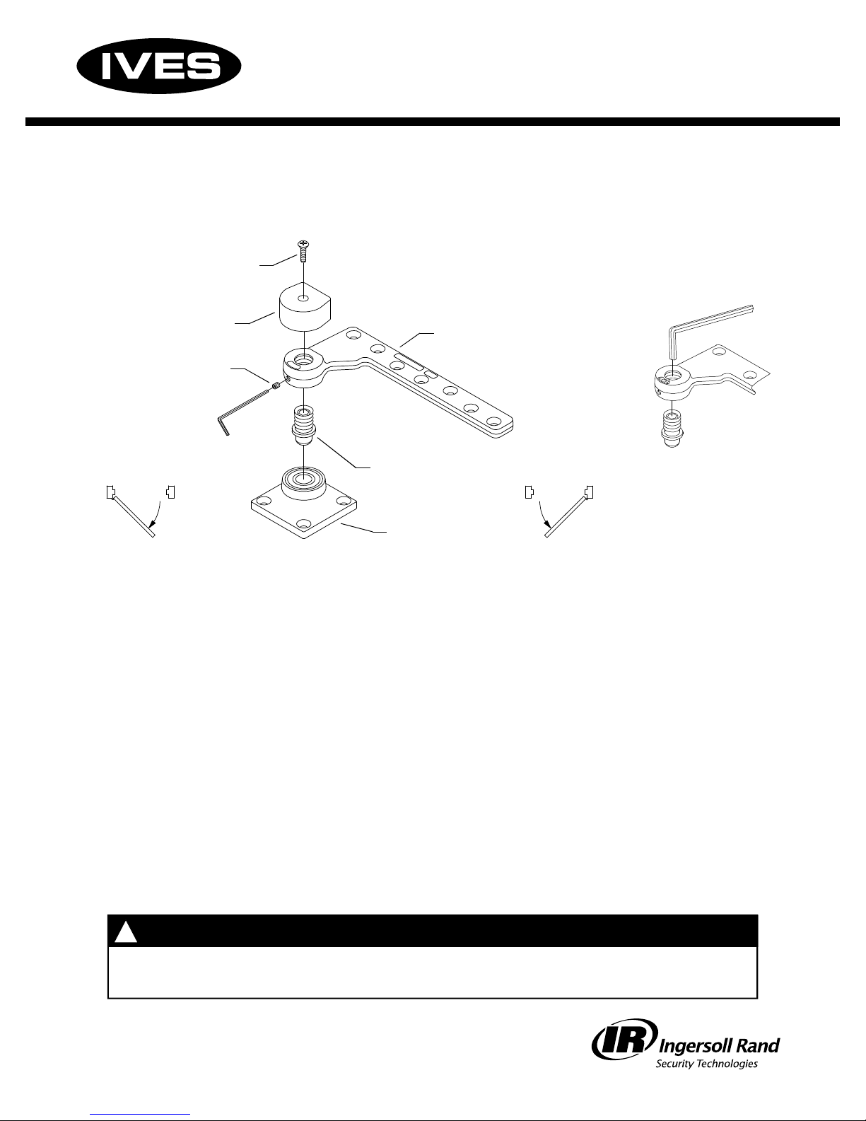
1-1/2” Offset Bottom Pivot
Right hand
Cap screw
installation shown;
left hand opposite
Pivot cap
3/32” set
screw
Right hand
installation
1. Prepare and mortise bottom of door and floor to receive pivot set. Determine pivot location
using dimensions on reverse side. Be sure to properly locate and mark pivot center point
of the base plate. The bottom pivot set is non-handed. The pivot shaft will thread into either
side of door leaf. To determine hand of door, see diagrams above.
2. Prepare bottom of door: Locate, drill, and tap 1/4-20 mounting holes for metal door. Locate
and drill pilot holes for #14 wood screws for wood door. Mount door leaf in bottom of door with
1/4-20 x 3/4” FHMS or #14 FHWS screws provided. Drill 7/16” dia. x 3/4” deep holes for base
plate mounting. Insert and secure anchor pins, then mount base plate to floor with screws provided.
Pivot shaft
Base plate
Door leaf
Left hand
installation
Figure 1
3. At this point, hang door. Refer to instruction sheet packed with top pivot for details.
4. If height adjustment is necessary for proper door clearance, adjust bottom pivot as follows:
A. Loosen set screw using 3/32” Allen wrench provided (see diagram above).
B. Use 5/16” Allen wrench to adjust pivot shaft height as needed (Figure 1).
C. Tighten set screw firmly.
5. Fasten pivot cap as shown. Secure with cap screw.
!
Improper pivot set installation can lead to personal injury or property damage. Follow
all instructions carefully. For questions contact Technical Support at 1-888-371-7331.
26488 Rev. 3 © 2006 Ingersoll-Rand Company Limited
CAUTION
!
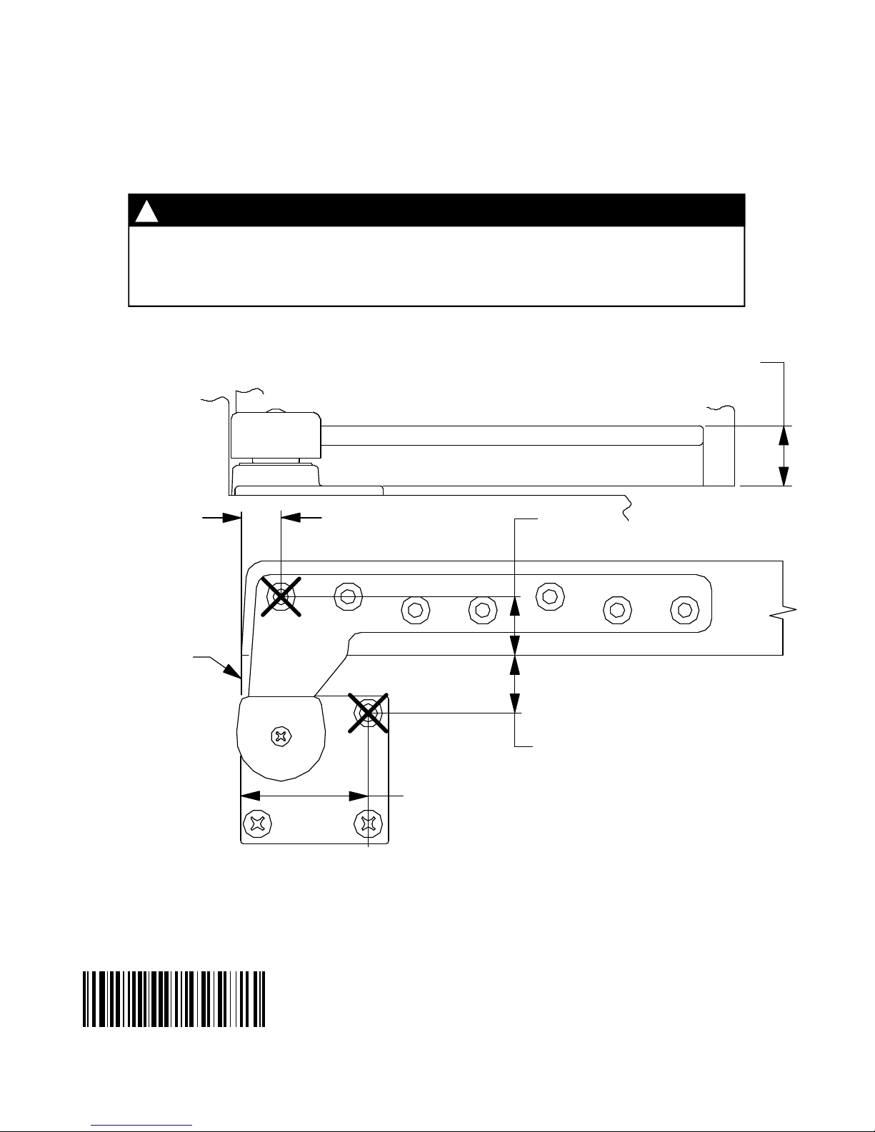
It is very important for installer to verify that center line of top pivot point lines up
with center line of bottom pivot point before final installation. Heel edge of door
must be beveled 1/8” in 2” as shown below.
NOTE
Depth of mortise will
*
vary depending upon
installation and/or
threshold height.
Edge of base
plate is flush
with edge of
door
3/4”
19 mm
1-1/8”
29 mm
1-1/16
27 mm
5/8”
*
16 mm
to
1-1/16”
27 mm
*
Right hand installation shown;
26488-00
2-3/8”
60 mm
left hand opposite
26488 Rev. 3
 Loading...