

IVC Displays NP-81XXXA, NP-8100A, NP-8120A, NP-8150A, NP-8170A User Manual
...
NP-81XXXA
(Human Machine Interface)
User Manual
Release Date _ Revision
Jan. 2010 V1.0
Nov. 2010 V1.1
Mar. 2011 V1.2
®2010 All Rights Reserved. IVC Displays, Inc.
www.ivcdisplays.com Page 1 N P-8XXXA Users Guide

Warning!___________________________________
This equipment generates, uses and can radiate radio frequency energy and if not installed and
used in accordance with the instructions manual, it may cause interference to radio communications.
It has been tested and found to comply with the limits for a Class A computing device pursuant to
FCC Rules, which are designed to provide reasonable protection against such interference when
operated in a commercial environment. Operation of this equipment in a residential area is likely
t o cause interference in which case the user at his own expense will be required to take whatever
measures may be required to correct the interference.
Electric Shock Hazard – Do not operate the machine with its back cover removed. There are
dangerous high voltages inside.
www.ivcdisplays.com Page 2 N P-8XXXA Users Guide

Packing List
Accessories (as ticked) included in this package are:
? AC power cable
? Driver & manual CD disc
? Other.___________________(please specify)
Safety Precautions
Follow the messages below to prevent your systems from damage:
? Avoid your system from static electricity on all occasions.
? Prevent electric shock. Don‘t touch any components of this card when the card is power-on.
Always disconnect power when the system is not in use.
? Disconnect power when you change any hardware devices. For instance, when you connect
a jumper or install any cards, a surge of power may damage the electronic components or the
whole system.
www.ivcdisplays.com Page 3 N P-8XXXA Users Guide

Table of Contents______________________
Warning!…………………………………………………………………………….……..….2
Packing List…………………………………………………………………………………..3
Safety Precautions…………………………………………………………………………..3
Chapter 1 Getting Started
1.1 Features…….……………………………………….……………………..6
1.2 Specifications……………………………...………………………….......6
1.3 Dimensions……..………………….…………………………….…..8
1.4 Installation of HDD…….………………………………………..14
1.5 Brief Description…………………………………………………….……16
1.6 Panel Mounting and VESA Mounting………………………………..17
Chapter 2 Hardware
2.1 Mainboard specifications.…….……………………………………..…..18
2.2 Installations memory……………………………….…………………...24
2.3 Connector and Jumpers…………………………………………….....25
Chapter 3 BIOS Setup
3.1 Operations after POST Screen................................................35
3.2 Standard CMOS Features...............................................37
3.3 Advanced BIOS Features.....................................................40
3.4 Advanced Chipset Features Setup............................... 43
3.5 Integrated Peripherals................................................................... 47
3.6 Power Managements Setup................................................. 53
3.7 PnP/PCI Configurations Setup...................................................... 56
3.8 PC Health Status…................................................................ 58
3.9 Load Fail-Safe/Optimized Defaults.............................................. 59
3.10 Set Administrator/User Password....................................... 61
3.11 Save & Exit Setup……………............................................. 62
3.12 Exit Without Saving……………………………………………………… 63
Chapter 4 Installation of Drivers
4.1 Intel Chipset Driver.…………………………...…………………………65
4.2 Intel Graphics Media Accelerator Driver...………………………..68
4.3 Realtek Gigabit LAN Device Driver…………………..……………….72
www.ivcdisplays.com Page 4 N P-8XXXA Users Guide

4.4 Realtek HD Driver Installation…….………..…………………75
Chapter 5 Touch Screen Installation
5.1 Introduction to Controller Board..…………………………..……………78
5.2 Windows 2000/XP USB Driver Installation for 6000 Boards………..….78
Figures
Figure 1.1: NP-8800A Dimensions……………………………………..…....8
Figure 1.2: NP-8100A Dimensions……………………………………..…...9
Figure 1.3: NP-8120A Dimensions………….………………………………10
Figure 1.4: NP-8150A Dimensions…...…….….……………………………11
Figure 1.5: NP-8170A Dimensions…...…….….……………………………12
Figure 1.6: NP-8190A Dimensions…...…….….……………………………13
Figure 1.7: Front View …………………...…………………………………….16
Figure 1.8: Rear View……………………...…………………………………...16
Figure 1.9: Panel Mounting and VESA Mounting……………..…………..17
Figure 2.1: Mainboard Overview………………………………………….....18
Figure 2.2: Mainboard Dimensions……………………………………….....19
Figure 2.3: Connector and Jumper Locations…………………………….....20
Figure 2.4 Installation of Memory Module…………………………..……24
Figure 5.1 Bird eye’s View of Control Board …………………………………78
www.ivcdisplays.com Page 5 N P-8XXXA Users Guide
Chapter 1 System
1.1 Features
n Fanless design
n 5.7”/8”/10.4”/12.1”/15” /17”/19” High brightness TFT LCD with resolution of
640x480/800x600/1024x768/1280x1024
n Intel® Atom™ N270 1.6GHz processor, FSB 533MHz
n NEMA 4/ IP 65 compliant front panel
n Sealed resistive touch screen
n One 200-pin SO-DIMM socket, up to 2GB DDR2 533MHz SDRAM
n DC 11~28V wide-range power input
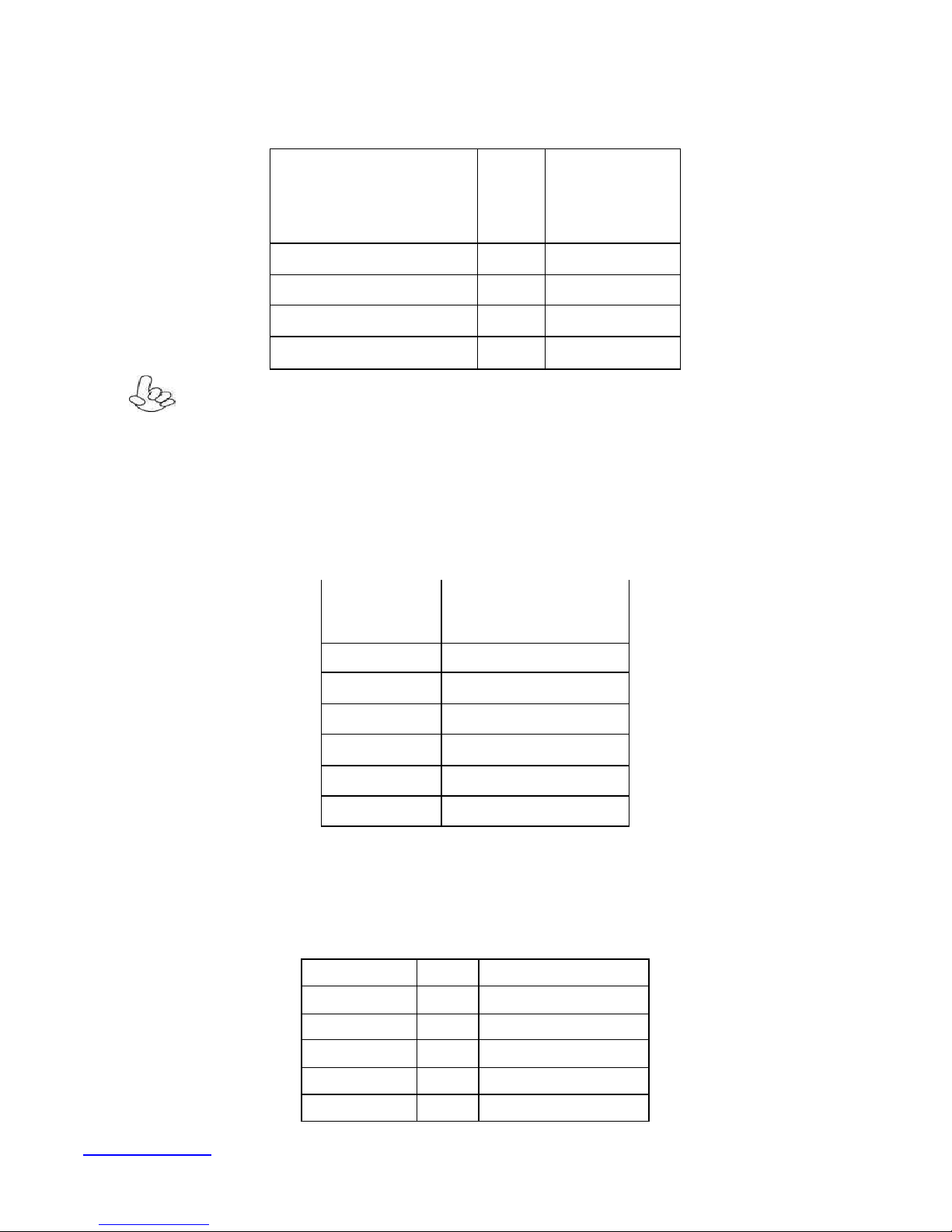
1.2 Specifications
System
Processor Intel® Atom™ N270 1.6GHz, FSB 533MHz
System Memory 1 x 200-pin SO-DIMM socket, support 533MHz up to 2GB SDRAM
System Chipset Intel® 945GSE + ICH7M
External I/O Port
Storage 1 x 2.5” SATA HDD, 1 x Internal CF slot
OS Support XP Pro, XP embedded, Windows &
LCD
Display Type TFT-LCD
Max. Resolution
NP-8800A, NP-8150A, NP-8170A
4 x USB port
2 x RJ-45 port
2 x DP-9 (COM 1/3, RS-232)
1 x DP-9 (COM 2, RS-232/422/485 support Full-duplex, Default RS-232)
** Optional RS-422/485 Module support half-duplex
1 x VGA port
1 x Audio Lin out
1 x DC power input
800x600 NP-8800A
1024x768 NP-8150A
1280x1024 NP-8170A
Max. Color 262K NP-8800A
16.2M NP-8150A, NP-8170A
Luminance (cd/m2)
www.ivcdisplays.com Page 6 N P-8XXXA Users Guide
400 (cd/m2) NP-8800A
350 (cd/m2) NP-8150A
300 (cd/m2) NP-8170A
View Angle
H:130° / V:120° (NP-8800A)
H:130° / V:110° (NP-8100A) H:140° / V:110° (NP-8120A)
H:140° / V:125° (NP-8150A)
H:160° / V:160° (NP-8170A / NP-8190A)
Backlight Lifetime
40,000hrs (NP-8800A/ NP-8120A)
30,000hrs (NP-8100A)
50,000hrs (NP-8150A / NP-8170A / NP-8190A)
Touch Screen
Type
Light Transmission
Analog resistive
80%
Power Supply
Power Input
DC 11~32V
Mechanical
Construction
Plastic molding front panel and metal housing / Black
(NP-8800A / NP-8100 A / NP-8120A / NP-8150 A)
Steel Metal front panel and housing / Black (NP-8170A / NP-8190A)
IP Rating
Mounting
IP 65 on Front Panel
Panel / VESA 75x75 Mount
Dimension 231 (W) x176 (H) x99 (D) mm (NP-8800A)
Environmental
Operating Temperature
Storage Temperature
Storage Humidity
Certificate
1.3 Dimensions
317 (W) x243 (H) x76 (D) mm (NP-8100A)
317 (W) x243 (H) x76 (D) mm (NP-8120A)
410 (W) x310 (H) x83 (D) mm (NP-8150A)
439 (W) x348 (H) x84 (D) mm (NP-8170A)
484 (W) x400(H) x 94 (D) mm (NP-8190A)
0~50 ? C
-20~60 ? C
10~90% @40? non-condensing
CE/FCC Class A
www.ivcdisplays.com Page 7 N P-8XXXA Users Guide
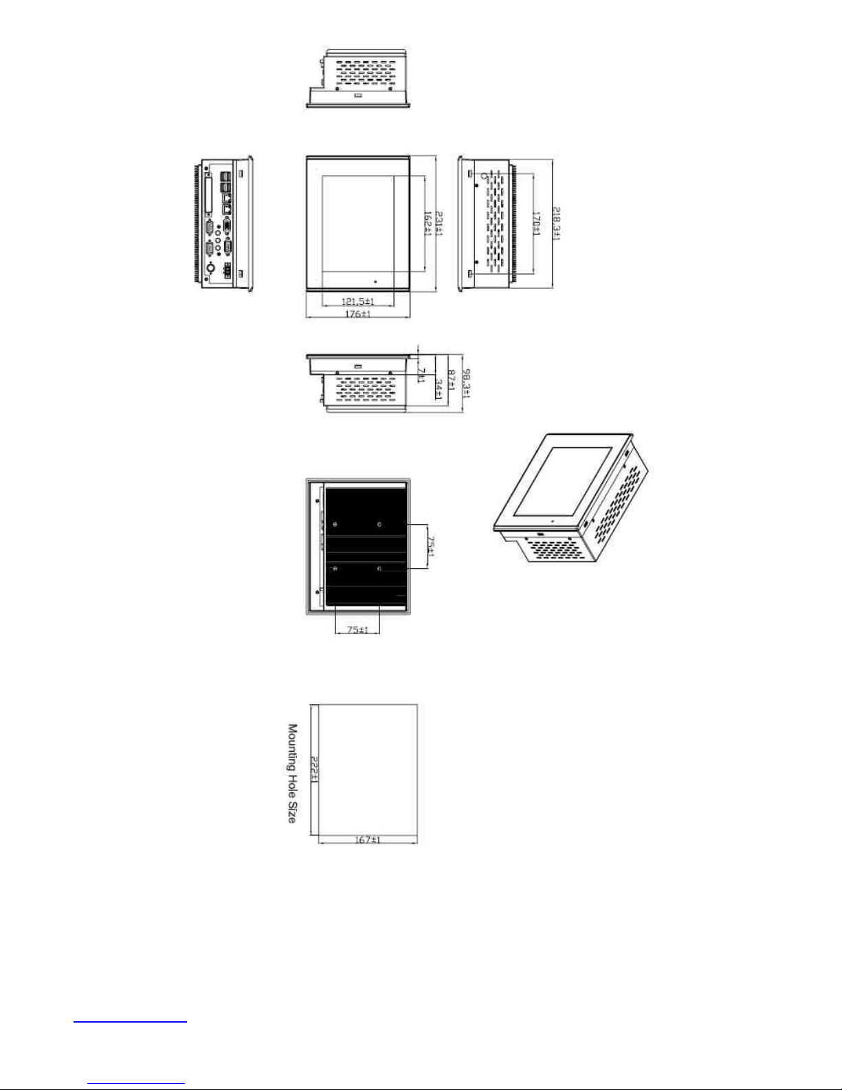
Figure 1.1: Dimensions of the NP-8800A
www.ivcdisplays.com Page 8 N P-8XXXA Users Guide

Figure 1.2: Dimensions of the NP-8100A
www.ivcdisplays.com Page 9 N P-8XXXA Users Guide
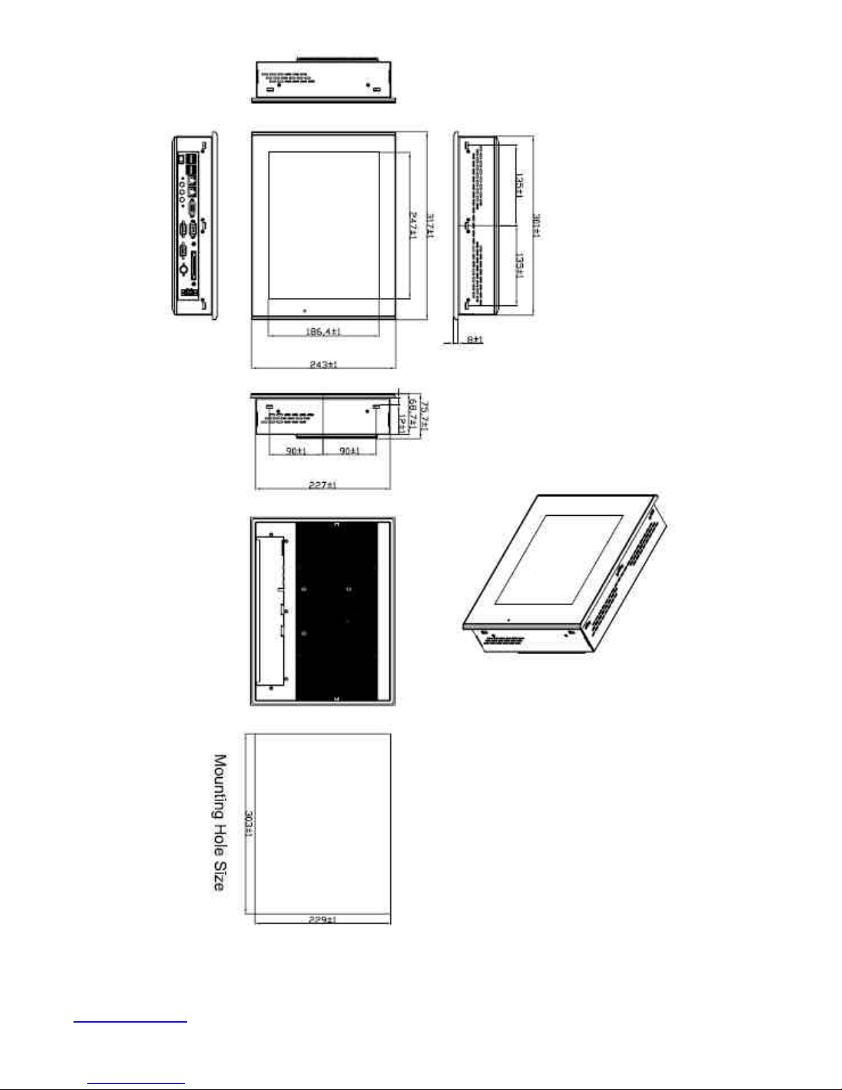
Figure 1.3: Dimensions of the NP-8120A
www.ivcdisplays.com Page 10 NP-8XXXA Users Guide
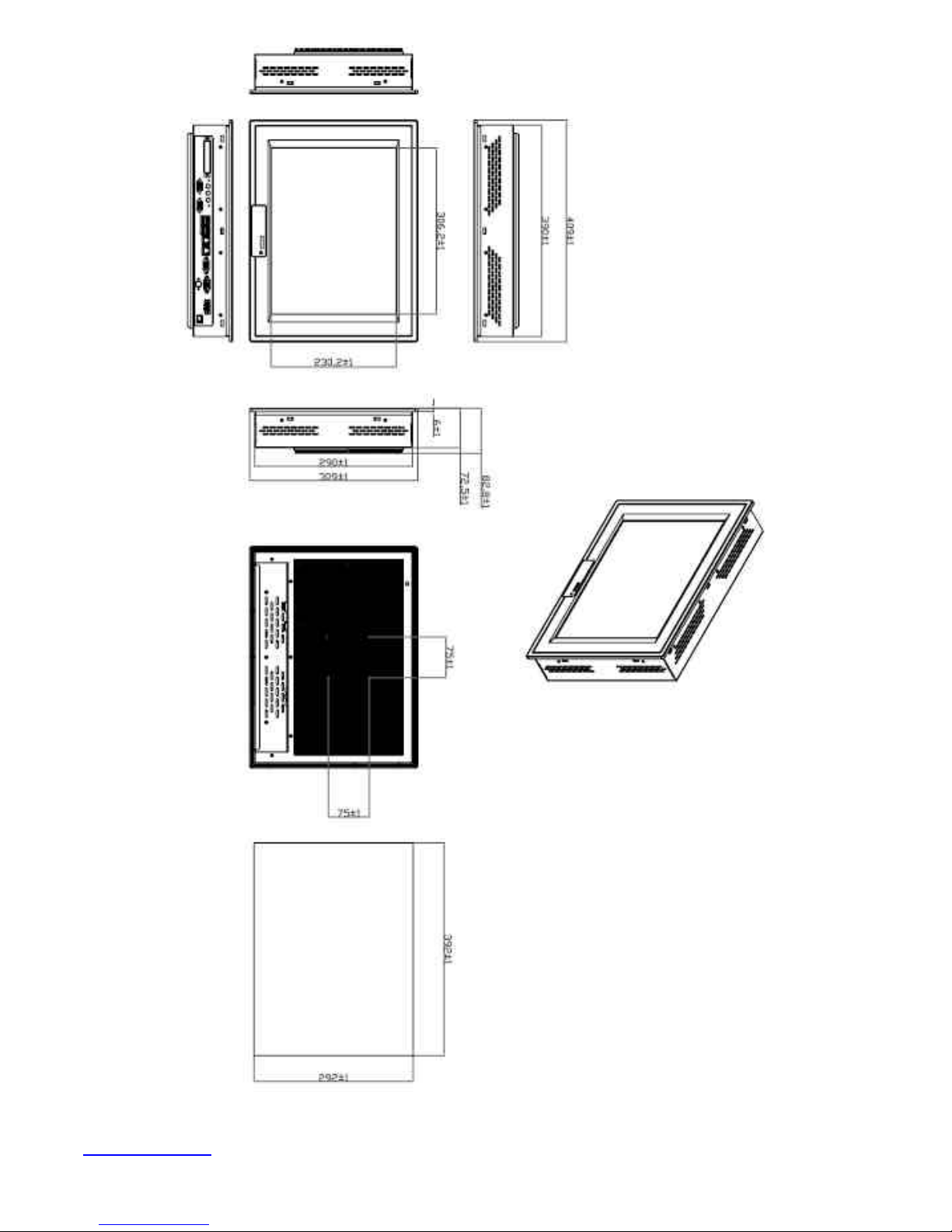
Figure 1.4: Dimensions of the NP-8150A
www.ivcdisplays.com Page 11 NP-8XXXA Users Guide
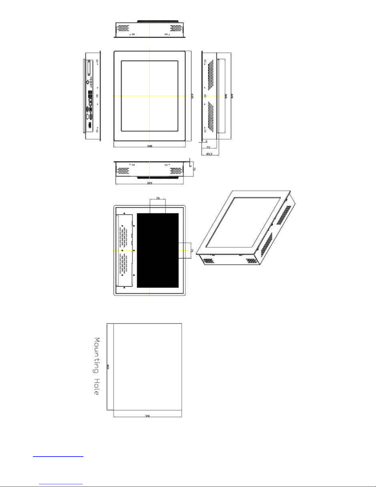
Figure 1.5: Dimensions of the NP-8170A
www.ivcdisplays.com Page 12 NP-8XXXA Users Guide
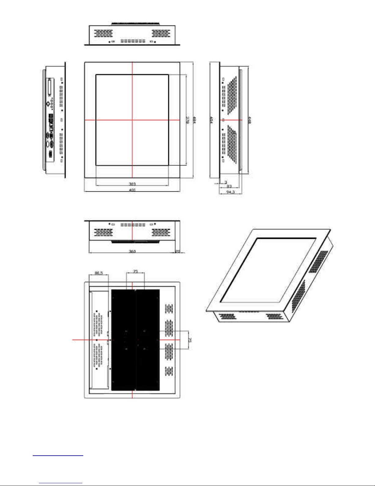
Figure 1.6: Dimensions of the NP-8190A
www.ivcdisplays.com Page 13 NP-8XXXA Users Guide
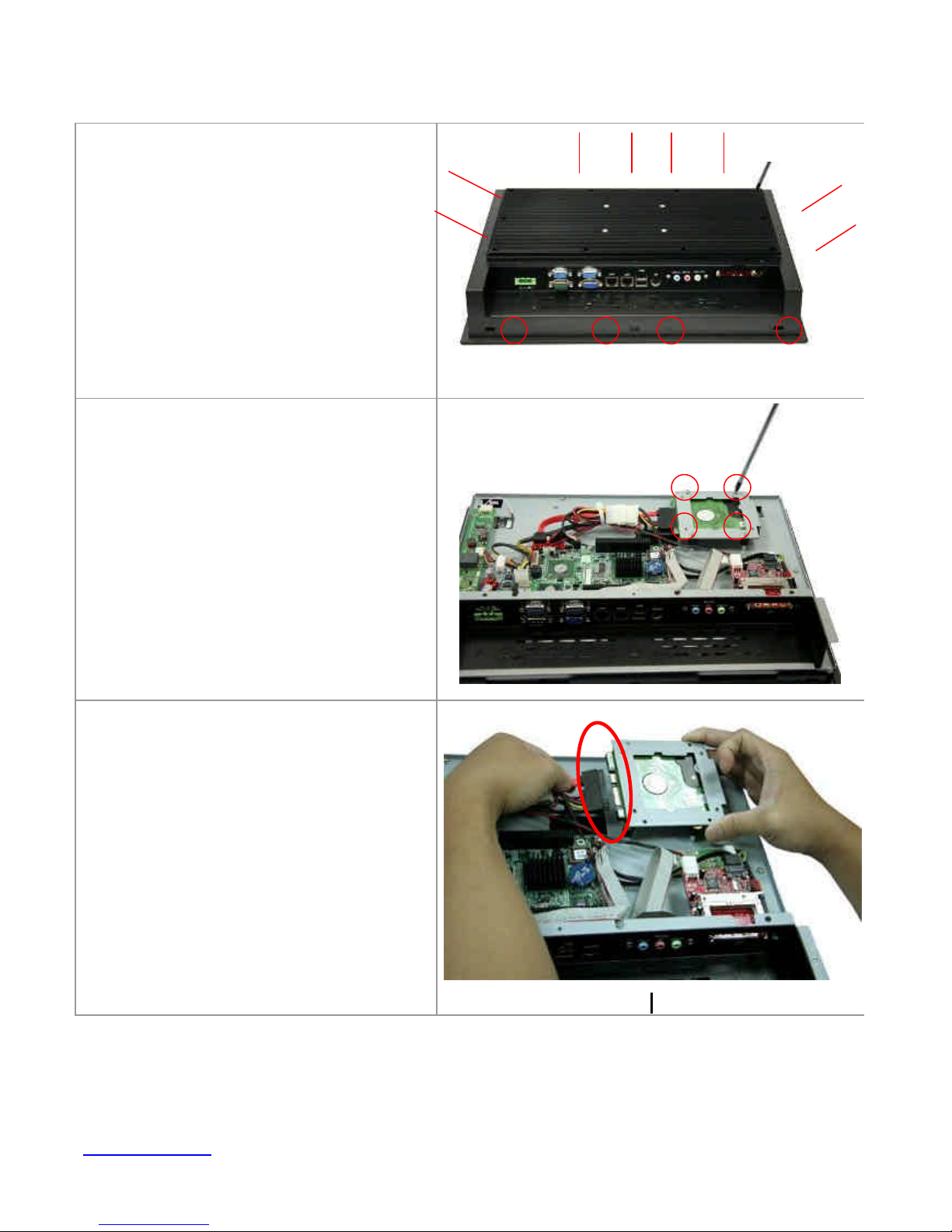
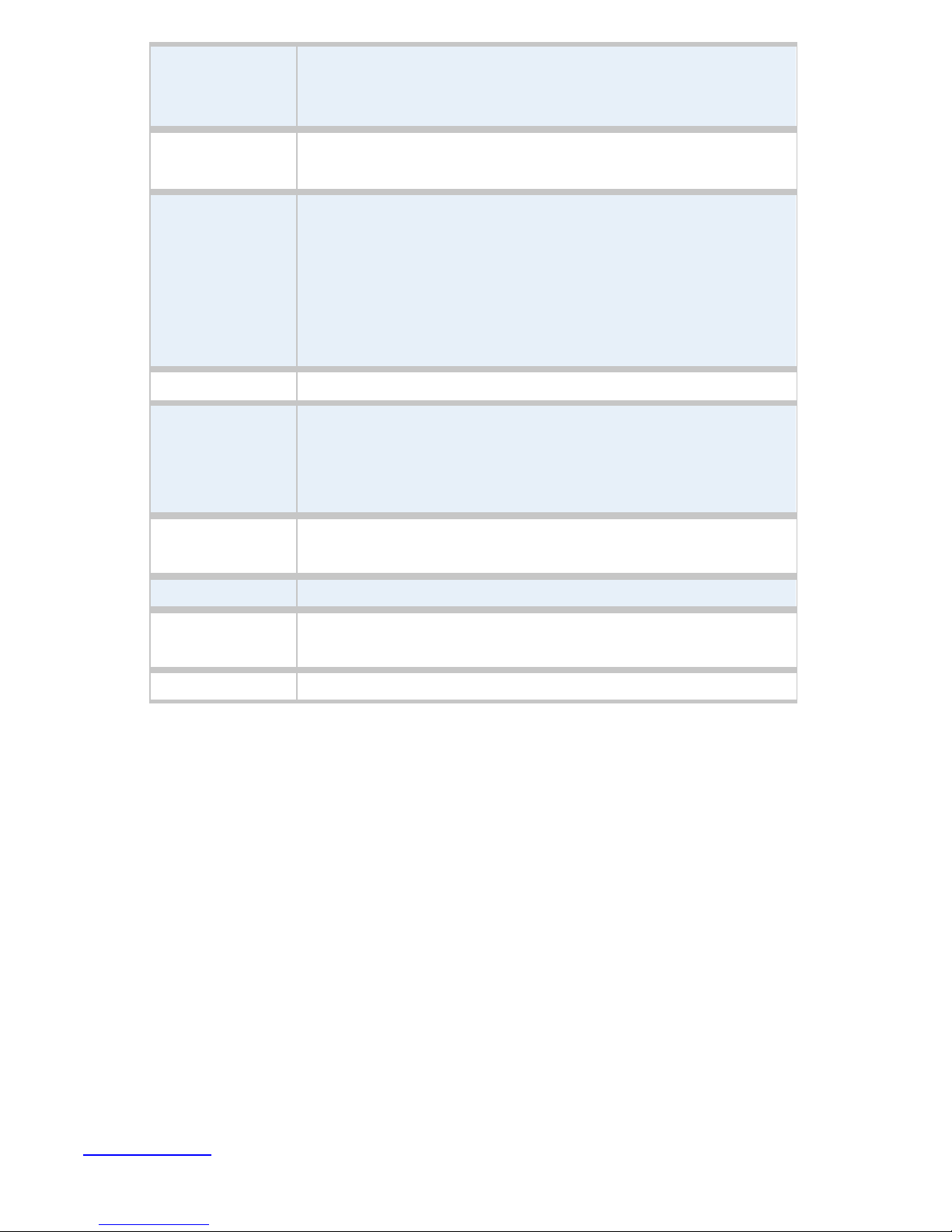
1.4 Installation of HDD
Step 1
There are 12 screws to deal with when
enclosing or removing the chassis.
Step 2
Get the HDD screwed to the bracket with
the four screws as shown by the arrows in
the picture.
Step 3
Connect the cable to the HDD as shown in
the picture, making sure the red stripe of
the cable is rightly positioned.
www.ivcdisplays.com Page 14 NP-8XXXA Users Guide
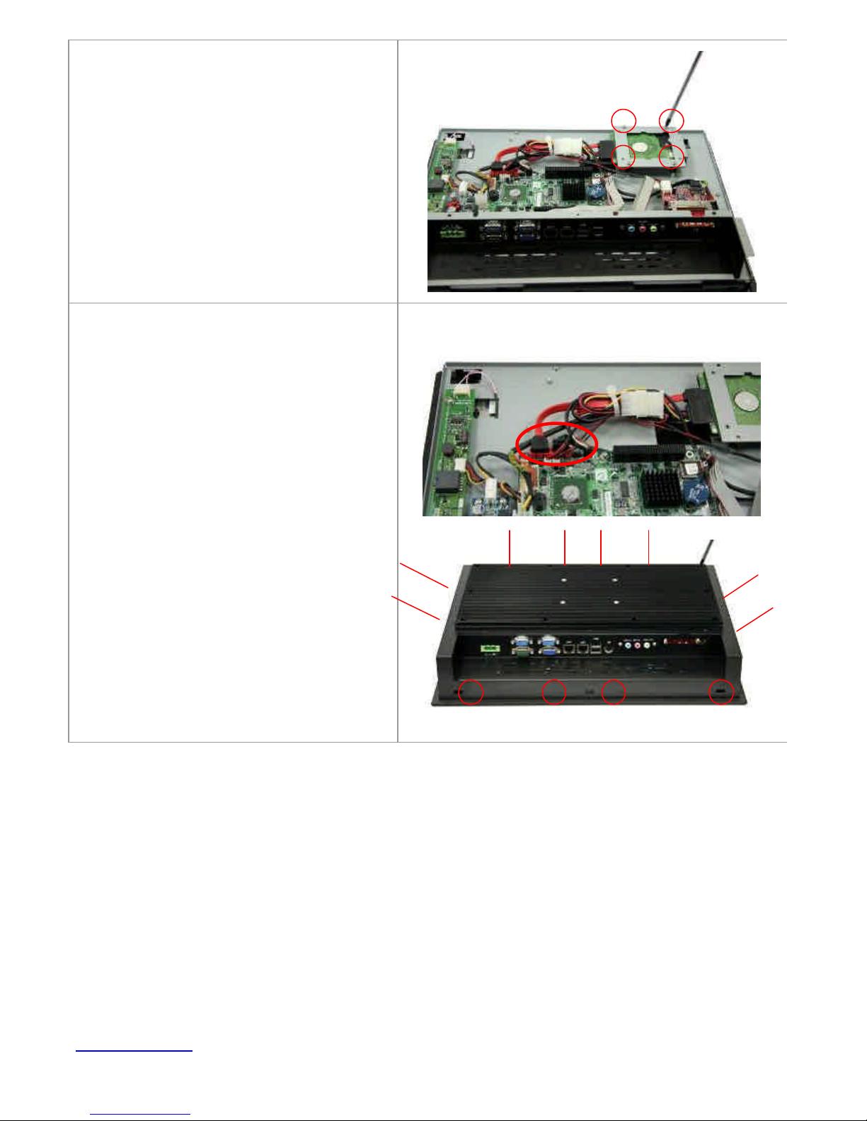
Step 4
Get the four screws as circled tightened to
secure the HDD. As shown in the picture
Step 5
Connect the other end of the cable to the
SATA connect as shown in the picture.
Step 6
That’s how it should look after it has been
installed.
www.ivcdisplays.com Page 15 NP-8XXXA Users Guide
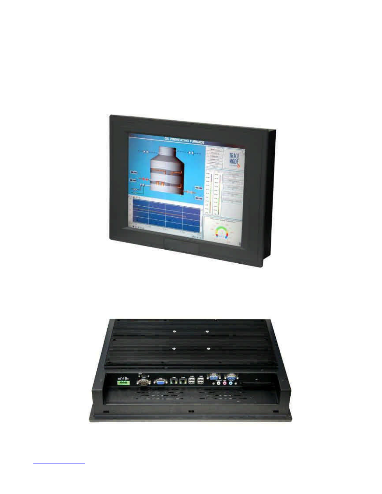
1.5 Brief Description of the NP-8xxxA
The NP-8XXXA is a power-optimized and delivers robust performance-per-watt for embedded HMI.
The powered by an Atom™ N270 processor, implemented in 45nm technology. It comes with a
compact flash slot, 2.5-inch hard disk drive, DDR2 memory, 3 serial ports, audio, 2 Ethernet, DC input,
and 2 USB ports. The unit supports Windows XP, Windows XPP and Embedded The compact, fanless
touch panel computer is ideal for use as Web Browser, Terminal and HMI at all levels of automation
control.
Figure 1.7: Front View of NP-8150A
Figure 1.8: Rear View of NP-8150A
www.ivcdisplays.com Page 16 NP-8XXXA Users Guide
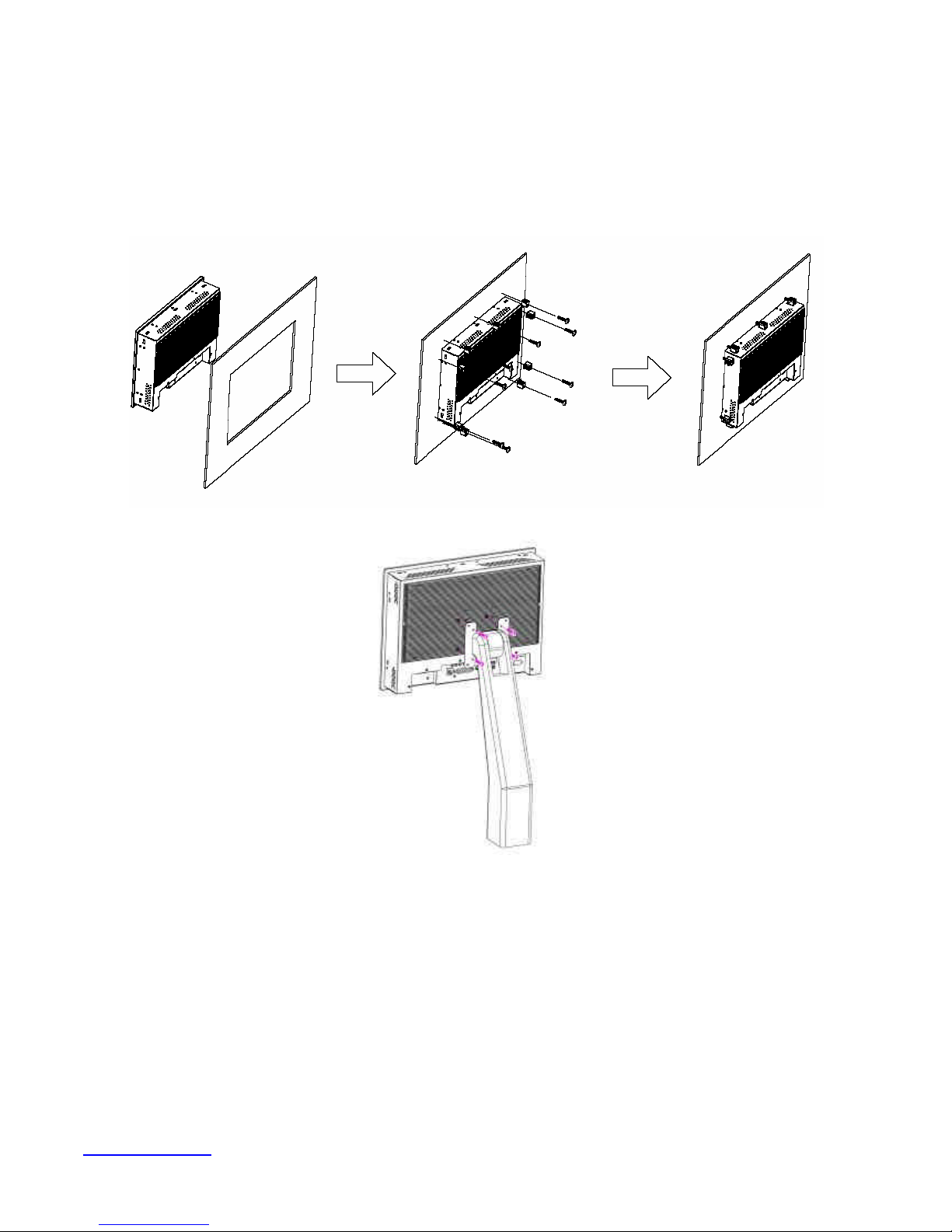
1.6 Panel Mounting and VESA Mounting of NP-8xxxA
The NP-8xxxA HMI is designed to be panel-mounted and VESA mounted as shown in Picture. Just
carefully place the unit through the hole and tighten the given 10 screws from the rear to secure the
mounting.
Figure 1.9 Panel mounting and VESA mounting of the NP-8xxxA
www.ivcdisplays.com Page 17 NP-8XXXA Users Guide
Chapter 2 Hardware
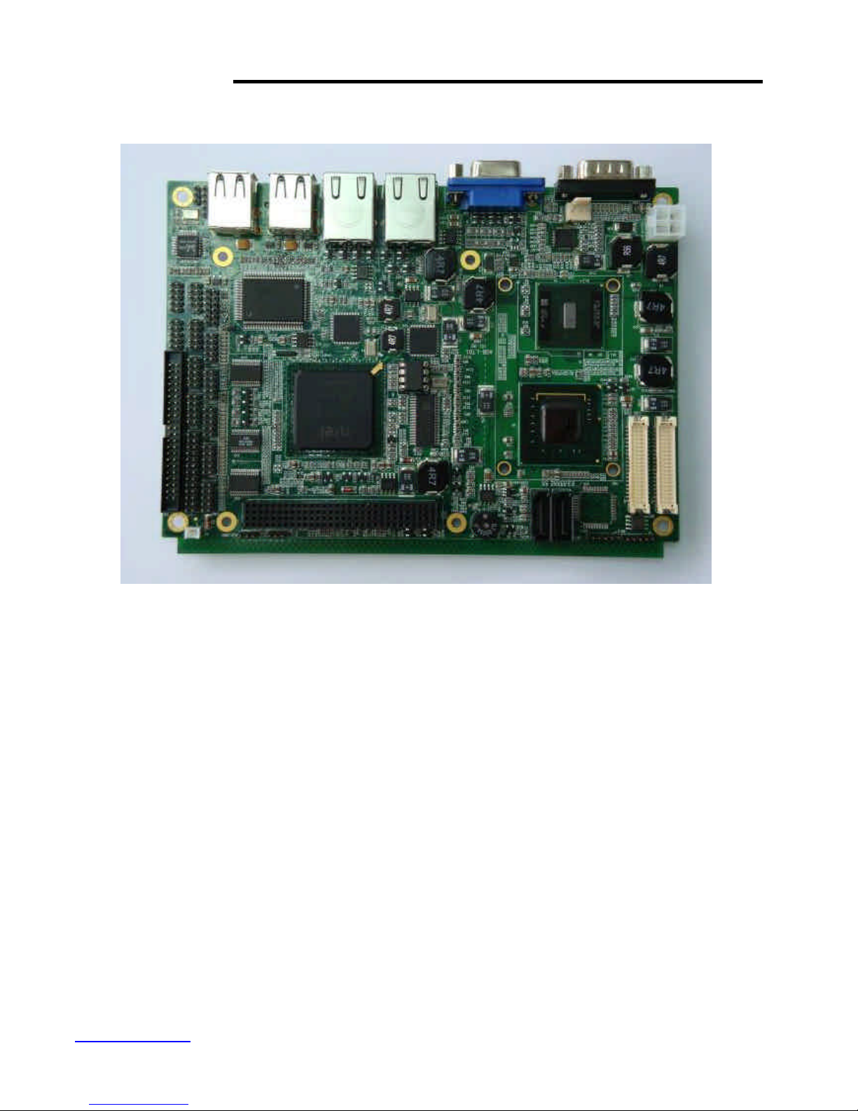
2.1 Mainboard Specifications
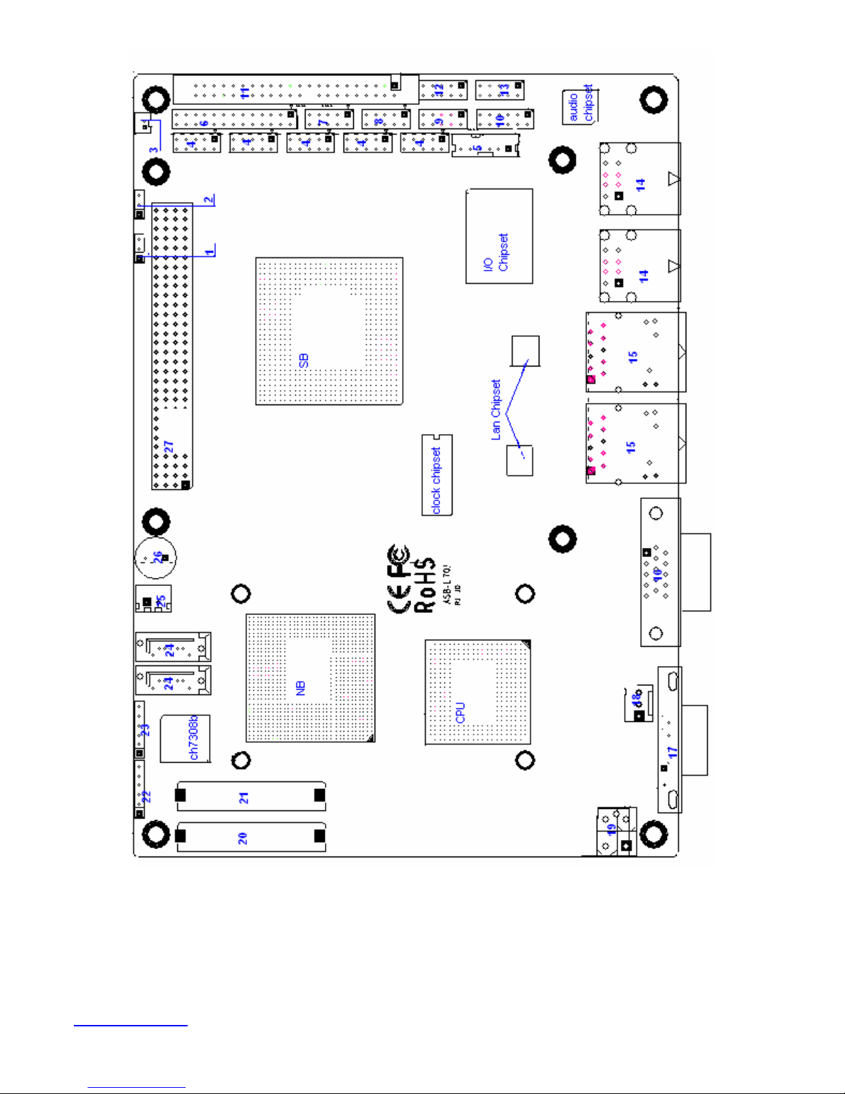
Figure 2.1: Mainboard Overview
www.ivcdisplays.com Page 18 NP-8XXXA Users Guide
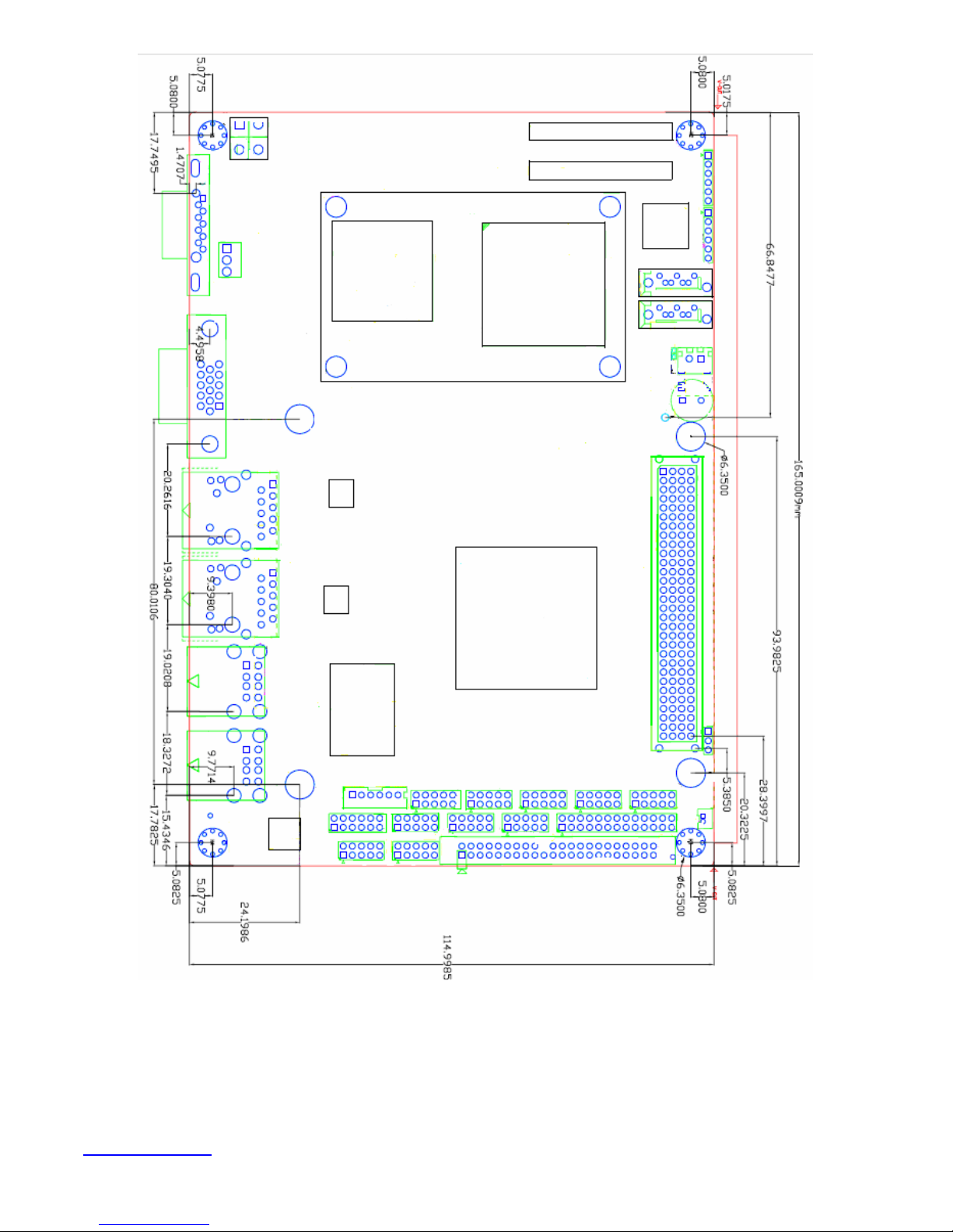
Figure 2.2: Mainboard Dimensions
www.ivcdisplays.com Page 19 NP-8XXXA Users Guide
www.ivcdisplays.com Page 20 NP-8XXXA Users Guide
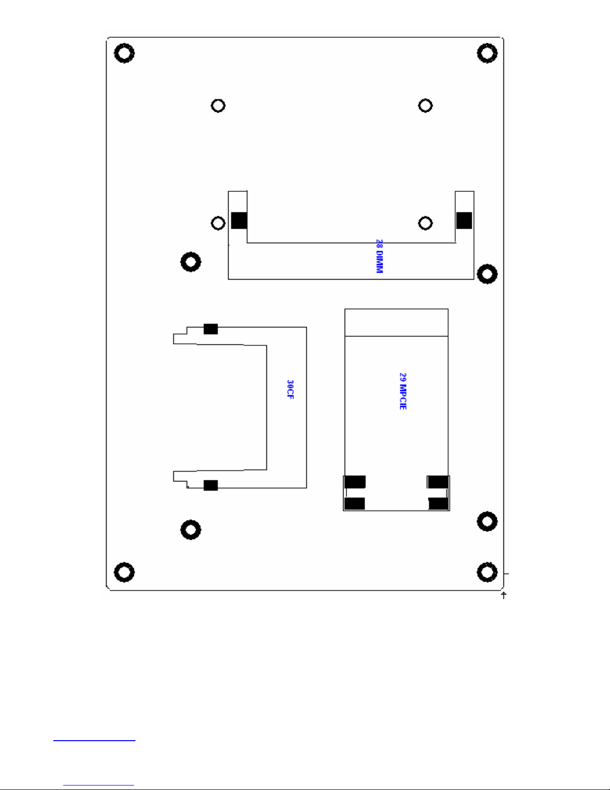
Figure 2.3: Connector and Jumper Locations
www.ivcdisplays.com Page 21 NP-8XXXA Users Guide
Ethernet
Mainboard Specifications
Board Size 165 x 115mm
CPU Support
Chipset
Memory Support
Graphics
Super I/O
BIOS
Storage
Network
Intel Atom N270 1.6 GHz with 533MHz FSB
Intel 945GSE + Intel ICH7M
1x200pin 533/400MHz DDR2 SO-DIMM support, up to 2GB
SDRAM
Intel Graphics Media Accelerator 950VGA integrated in Intel
945GSE
18-bit dual-channel LVDS integrated in Intel 945GSE
18/24 bit dual-channel LVDS support by Chrontel CH7308B
1 x DB15 Female connector for external
Winbond W83627UHG
Award BIOS
2 x SATA Connector
1 x Compact Flash II Slot
1 x 44-pin IDE Connector
2 x Gigabit Ethernet Port by RJ45 with LED indicators -
controller :
USB
Serial
Digital I/O
Battery
Audio
Printer
Ke yboard
/Mouse
2 x PCIe by one bus Realtek 8111D
4 x USB 2.0 stack port for external
2 x USB 2.0 header for internal
1 x RS232 port, DB9 connector for external (COM1),
pin 9 w/5V/12V/Ring select
1 x RS232/422/485 (Full-duplex) select header for internal
(COM2), default RS232
4 x RS232 header for internal (COM3 – COM6)
8-bit digital I/O by header
4-bit digital Input
4-bit digital Output
Support CR2477 battery by 2 -pin header
Support Audio via Realtek ALC662 HD audio decoder
Support Line-in, Line-out, MIC by 2x5-pin header
1x LPT port by 2x13-pin header
1x PS2 keyboard/mouse by 1x6 -pin wafer connector
www.ivcdisplays.com Page 22 NP-8XXXA Users Guide
Expansion Bus
1x PC 104+ connector (PCI master 4, jumper for +3.3V & 5V
select)
1x PCIe ( PCI-e 1x +SMBUS+USB2. 0 ) mini card
Power
Management
Front I/O
Watchdog Timer
External I/O port
Temperature
Humidity
DC12V input
1 x 2x2-pin power input connector
by 2x5-pin header
Power on/off switch
Reset switch
Power LED status
HDD LED status
Buzzer
Software programmable 1 – 255 second by Super I/O
1 x COM Port (COM1)
4 x USB 2.0 Ports (stack)
2 x RJ45 GbE Port (10/100/1000Mbps)
1 x VGA Port
Operating: 0 – 60 degree C
Storage: -20 – 80 degree C
5% - 95%, non-condensing, operating
Power
Consumption
EMI/EMS
12V @1.4 5A (Intel N270 processor with 1GB DDR2 DRAM)
CE/FCC class A
www.ivcdisplays.com Page 23 NP-8XXXA Users Guide
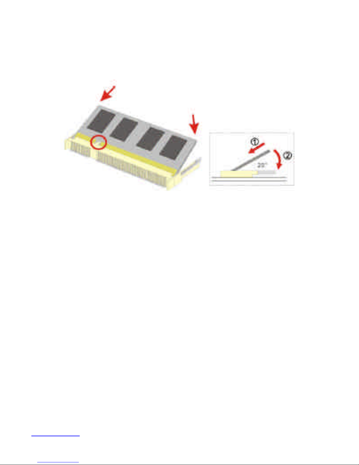
2.2 Installations
2.2.1 SO-DIMM Installation
To install a SO-DIMM into a SO-DIMM socket, please follow the steps below and refer to picture.
Figure 2.4: Installation of Memory Module
Step 1:
Locate the SO-DIMM socket. Place the NANO-945GSE2 on an anti-static pad with the solder side
facing up.
Step 2:
Align the SO-DIMM with the socket. The SO-DIMM must be oriented in such away that the notch in
the middle of the SO-DIMM must be aligned with the plastic bridge in the socket.
Step 3:
Insert the SO-DIMM. Push the SO-DIMM chip into the socket at an angle. (See Figure 2.3)
Step 4:
Open the SO-DIMM socket arms. Gently pull the arms of the SO-DIMM socket out and push the rear
of the SO-DIMM down
www.ivcdisplays.com Page 24 NP-8XXXA Users Guide

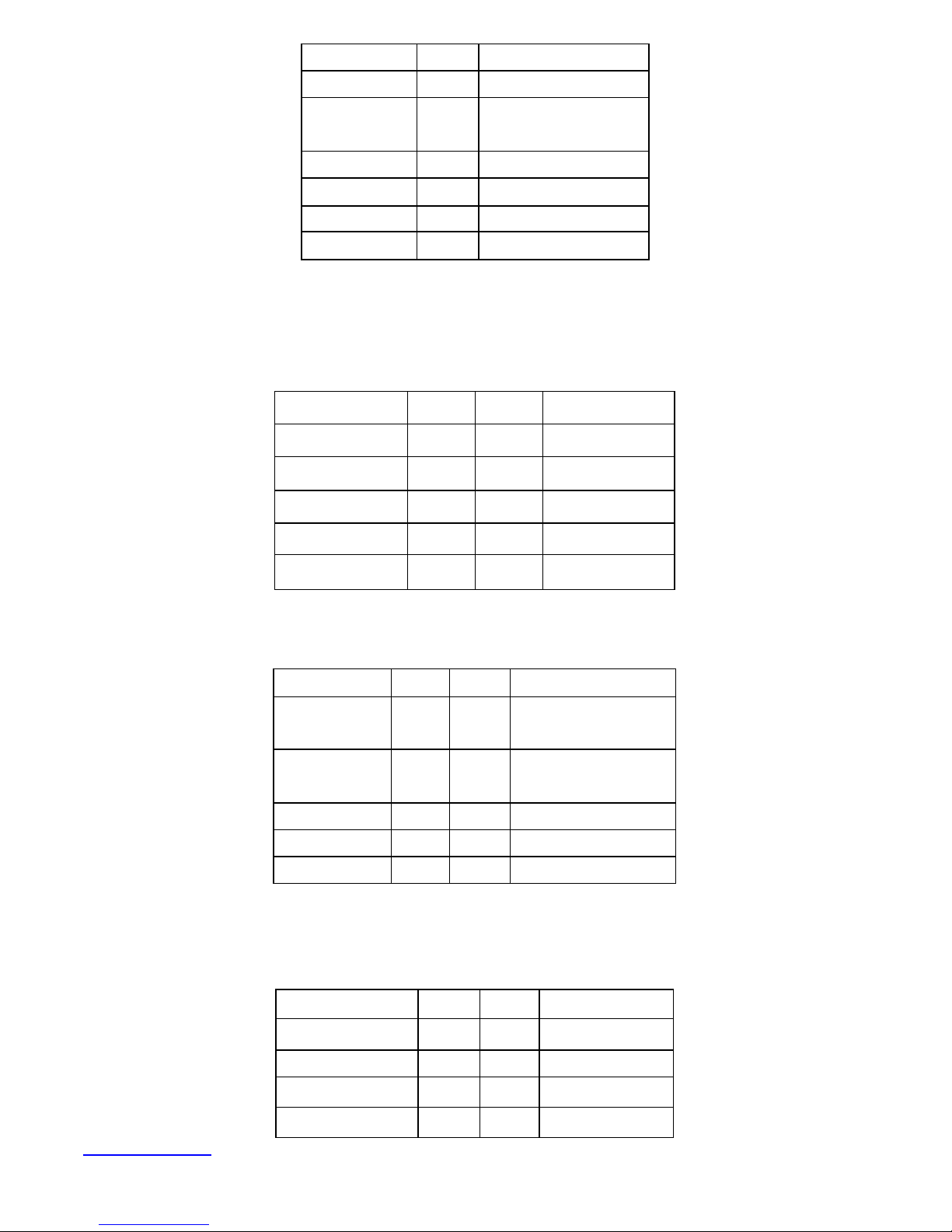
2.3 Onboard Jumpers and Port Pin outs
1. JVCCIO (2.0MM 1X3) PC104+ port voltage selection jumper: select voltage for PC104+
device
JVCCIO PC104+ VCCIO Voltage
CLOSE 1-2 +3.3V (default)
CLOSE 2-3 +5V
2. JCLR_CMOS (2.0MM 1X3) CMOS clear jumper: CMOS clear operation will permanently
reset old BIOS settings to factory defaults.
JCLR_CMOS CMOS
CLOSE 1-2 NORMAL (default)
CLOSE 2-3 CLEAR CMOS
Procedures of CMOS clear:
1. Turn off the system and unplug the power cord from the power outlet;
2. To clear the CMOS settings, use the jumper cap to close pins 2 and 3 for about 3 seconds
then reinstall the jumper clip back to pins 1 and 2.
3. Power on the system again;
4. When entering the POST screen, press the <DEL> key to enter CMOS Setup Utility to load
optimal defaults;
5. After the above operations, save changes and exit BIOS Setup.
3. BAT (1.25.0MM 1X2) Battery port: a 3.3V battery is embedded to provide power for CMOS.
PIN# Signal Name
PIN1 VBAT
PIN2 Ground
www.ivcdisplays.com Page 25 NP-8XXXA Users Guide
4.COM2-COM6 (2.0MM 2X5) COM2~COM6 port: up to 5 standard RS232 ports are
provided. They can be used directly via COM adapter cable connection.
Signal Name Pin# Pin# Signal Name
DCD 1 2 RXD
TXD 3 4 DTR
Ground 5 6 DSR
RTS 7 8 CTS
RI 9 10 NC
Note: COM2 port is controlled by pins No.8~10 of JCOM. For details, please refer to
description of JCOM.
5.KB/MS (2.0MM 1X6) PS/2 keyboard/mouse port: the port can be connected to PS/2
keyboard or mouse via a dedicated adapter cable for direct use.
Pin# Signal Name
1 KBDATA
2 MSDATA
3 Ground
4 +5V
5 KBCLK
6 MSCLK
6. LPT (2.0MM 2X13) Parallel port: a standard 26 pin parallel port is provided to connect
parallel peripherals as required.
Signal Name Pin# Pin# Signal Name
PSTB# 1 2 PD0
PD1 3 4 DP2
DP3 5 6 DP4
DP5 7 8 DP6
DP7 9 10 ACK#
www.ivcdisplays.com Page 26 NP-8XXXA Users Guide
BUSY 11 12 PE
SLCT 13 14 AFD#
ERR# 15 16 INIT#
SLIN# 17 18 Ground
Ground 19 20 Ground
Ground 21 22 Ground
Ground 23 24 Ground
Ground 25 26 Ground
7. GPIO (2.0MM 2X5) General-purpose input/output port: it provides a group of
self-programming interfaces to customers for flexible use.
Signal Name Pin# Pin# Signal Name
GPIO20 1 2 GPIO60
GPIO21 3 4 GPIO61
GPIO22 5 6 GPIO62
GPIO23 7 8 GPIO63
Ground 9 10 +5V
8. COM22 (2.0MM 2X5): it provides selectable RS422/485 serial signal output.
Signal Name Pin# Pin# Signal Name
A 1 2 Terminal
Resistance
B 3 4 Terminal
Resistance
Z 5 6 NC
Y 7 8 NC
Ground 9 10 NC
9. USB4 (2.0MM 2X5) Front USB connector: it provides two USB ports via a dedicated USB
adapter cable.
Signal Name Pin# Pin# Signal Name
+5V 1 2 +5V
USB_P6_DN 3 4 USB_P7_DN
USB_P6_DP 5 6 USB_P7_DP
Ground 7 8 Ground
www.ivcdisplays.com Page 27 NP-8XXXA Users Guide
NC 9 10 Ground
Note:
Before connection, make sure that pin out of the USB adapter is in accordance with that of the
said tables. Any inconformity may cause system down and even hardware damages.
10. JCOM (2.0MM 2X6) COM1/2 setup jumper: pin 1~6 are used to select signal out of pin 9
of COM1 port; pin 7~12 are used to select output type for COM2 port (RS232 or RS422/485
Full-Duplex).
JCOM Function
CLOSE 1-2 COM1 Pin9=RI (default)
CLOSE 3-4 COM1 Pin9=+5V
CLOSE 5-6 COM1 Pin9=+12V
CLOSE 7-9
COM2 FOR RS232 FROM COM2
CLOSE 8-10
CLOSE 9-11
CLOSE 10-12
Note:
1. As determined by its hardware design, the board features full-duplex RS485 communication.
Like RS422, a four-wire connection is necessary.
2. Since COM2 and COM22 use the same address, they cannot work at the same time.
(default)
COM2 FOR RS485/RS422 FROM
COM22
11. IDE (2.0MM 2X22) IDE connector: the motherboard provides a 44-pin IDE connector for
connection of 2.5' IDE hard disk drivers and supports up to 2 IDE devices.
Signal Name Pin# Pin# Signal Name
RESET 1 2 Ground
IDE_PDD7 3 4 IDE_PDD8
IDE_PDD6 5 6 IDE_PDD9
IDE_PDD5 7 8 IDE_PDD10
IDE_PDD4 9 10 IDE_PDD11
IDE_PDD3 11 12 IDE_PDD12
IDE_PDD2 13 14 IDE_PDD13
IDE_PDD1 15 16 IDE_PDD14
IDE_PDD0 17 18 IDE_PDD15
Ground 19 20 NC
DREQ 21 22 Ground
www.ivcdisplays.com Page 28 NP-8XXXA Users Guide
 Loading...