

iVAC Pro Remote User Guide.
Provisional layout
Front Cover and Pages 1 to 10.
Front Cover
iVAC Pro Remote User Guide.
Picture
MBright Tools iVAC Inc.
www. Ivacswitch.com.
iVAC Pro Remote User Guide P1 and 2
Table of Contents.
Physical Features.
General Description.
System Address
Tool Address
Replacing Batteries
Specifications
Regulatory approval
.
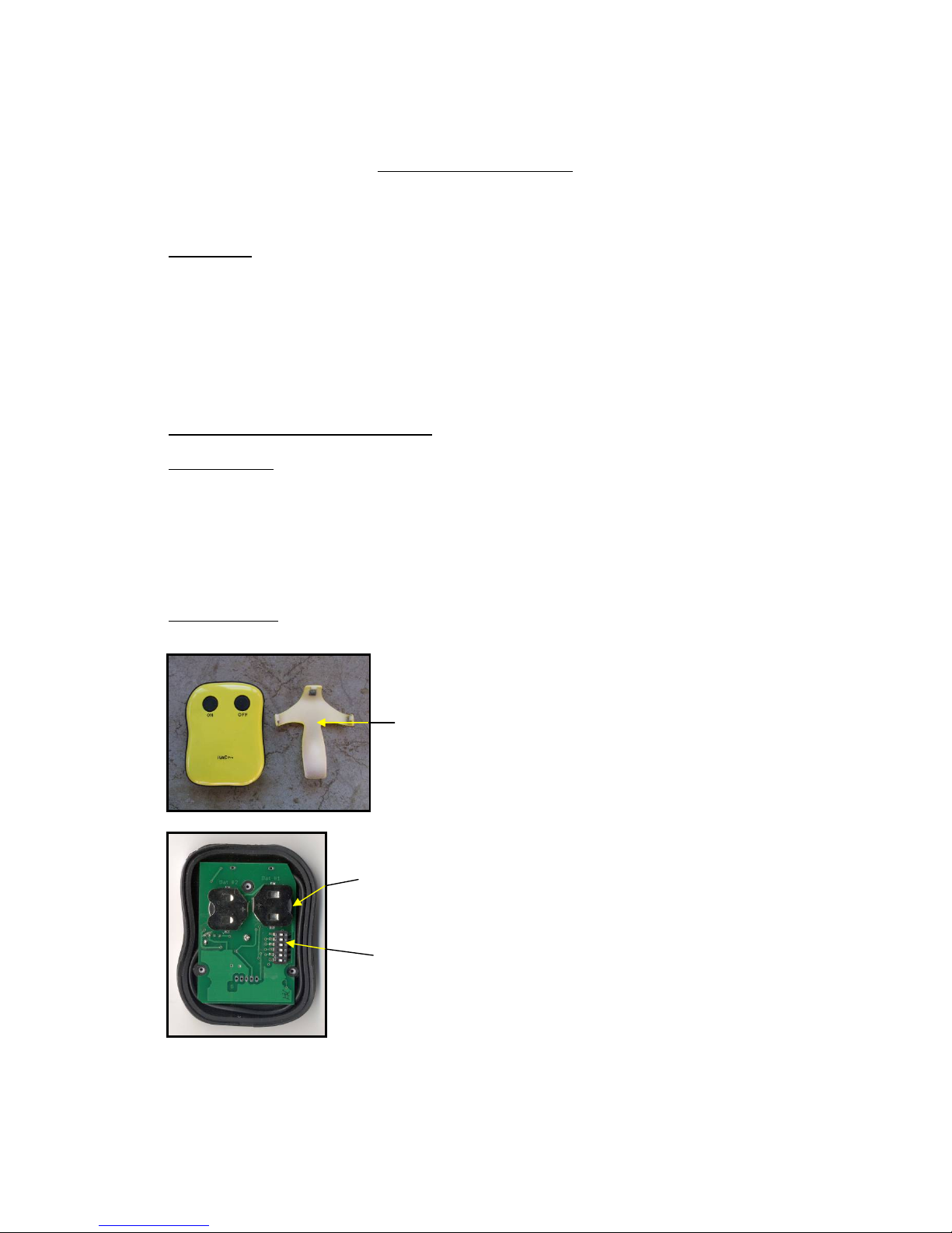
Physical Features
CR2032
Batteries
DIP Program
Switch.
Belt Clip

iVAC Pro Remote User Guide P3 and 4
General Description.
The ‘iVAC Pro Remote’ has been added to the ‘iVAC Pro
System’ to operate in conjunction with an ‘iVAC Pro Switch’
and enable a dust collector to be controlled remotely, by
means of a manual operation.
The ‘iVAC Pro Remote’ can be programmed by means of
an internal DIP program switch to operate on one of four
System Addresses and one of eight Tool Addresses, similar
to an ‘iVAC Pro Tool’. (Refer to iVAC Pro System User Guide.)
The ‘iVAC Pro Remote’ is intended for indoor use in dry
locations only.
When the ON button is pressed, a radio frequency transmission
is sent to the ‘iVAC Pro Switch’ instructing it to turn on and
provide power to the dust collector. When the OFF button
is pressed, the power will be removed from the dust collector.
The Turn On Delay and Turn Off Time for the dust collector
will be as programmed in the ‘iVAC Pro Switch’.
To ensure consistent operation, it is recommended that the
buttons are operated for one to two seconds.
The Remote is housed in a plastic case
90mm x 70mm x 25mm.
An easily attached belt clip is also provided.
The rear cover is attached by three screws. Removing the
cover allows access to the batteries and the DIP program switch.
This allows the batteries to be changed and also to program
address functions of the ‘iVAC Pro Remote’ by means of
the six position DIP program switch.
There are two address functions, System Address and Tool
Address.
iVAC Pro Remote User Guide P5 and 6
System Address
A System consists of an’ iVAC Pro Switch’ and from one to
eight iVAC Pro Tools or iVAC Pro Remotes. There can be
any mix of Tools or Remotes.
By means of positions S1 and S2 of the Program Switch,
the Remote can be assigned to work on one of four System
Addresses, A, B, C or D.
The System Address enables up to four Systems to operate
independently while within communication range of each
other.
System Address
* factory setting
S1 S2
* A Off Off
B On Off
C Off On
D On On

iVAC Pro Remote User Guide P7 and 8
Tool Address
Each iVAC Pro Remote or iVAC Pro Tool must be assigned
an independent one of eight tool address. This information is
used by the Switch to enable it to know the status of each
individual iVAC Pro Tool or iVAC Pro Remote in the
System. The Tool Address is set by means of positions S3,
S4 and S5 of the Program Switch.
iVAC Pro Remote User Guide Pages 9 and 10
Replacing the batteries
The batteries have a useful life of 25,000 operations over a
3 year period.
To remove the batteries it is recommended to use the tip of
a pen or similar device and push from the inside edge of the
battery holder.
When replacing batteries, both batteries should be replaced
at the same time. The positive (+) side of the battery should
face away from the circuit board.
Specifications
Plastic housing ABS 94V0 plastic.
Powered by 2 CR2032 lithium batteries.
Rf Range 40’ line of sight.
Regulatory approval
This device complies with part 15 of the FCC rules.
Operation is subject to the following two conditions
(1) This device may not cause harmful i nterference, and (2)
this device must accept any interference received, including
interference that may cause undesired operation.
Caution: Changes or modifications not expressly approved by
the party responsible for compliance could void the users
authority to operate the equipment.
FCC ID: YCHIVACPRO IC 8940A-IVACPRO
Tool Address
* factory setting
S3 S4 S5
1 On Off Off
2 Off On Off
3 On On Off
4 Off Off On
5 On Off On
6 Off On On
* 7 On On On
8 Off Off Off
 Loading...