


REMOTE USER GUIDE
www. switch.com
MBright Tools iVAC Inc.
5570 Jill Street
.
Box 557 . Osgoode, Ontario Canada . K0A 2W0
Tel: 613 826 2200
.
Fax: 613 826 3300 . info@iVacSwitch.com

Table of Contents
1 Warnings
2 Physical Features
3 General Description
4 System Address
5 Tool Address
6 Replacing Batteries
7Specications
8 Regulatory Approval
1 Warnings
Please read the operating instructions before use.
The iVAC Pro Remote is intended for indoor use
in dry locations only. Used batteries should be
disposed of in a safe manner.
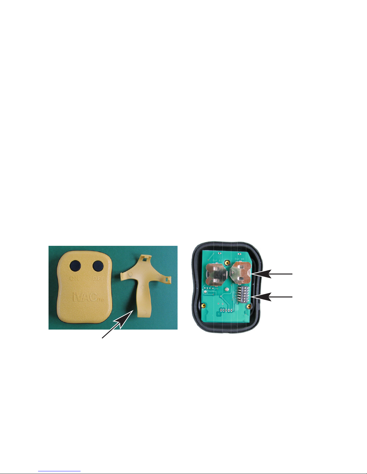
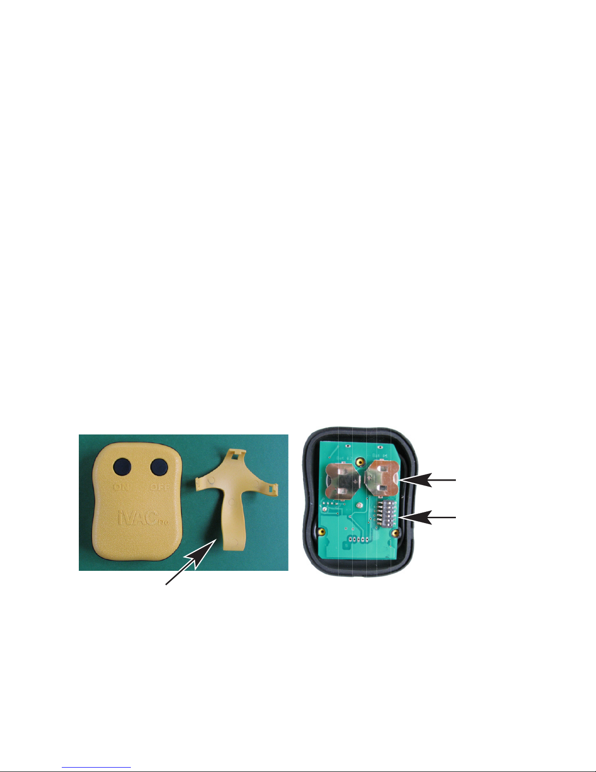
2 Physical Features
DIP
Program
Switch
CR2032
Batteries
Belt Clip

3 General Description
The ‘iVAC Pro Remote’ operates in conjunction
with an ‘iVAC Pro Switch’ and enables a dust
collector to be controlled remotely, by means of a
manual operation.
When the ON button is pressed, a radio
frequency transmission is sent to the ‘iVAC Pro
Switch’ instructing it to turn on and provide
power to the dust collector. When the OFF button
is pressed, the power will be removed from the
dust collector.
To ensure consistent operation, it is
recommended that the buttons are operated for
one to two seconds.
The ‘iVAC Pro Remote’ can be programmed
by means of an internal DIP Program Switch to

operate on one of four System Addresses and
one of eight Tool Addresses, similar to an ‘iVAC
Pro Tool’. (Refer to iVAC Pro System User Guide
supplied with the iVAC Pro Switch)
The iVAC Pro Remote is housed in a plastic case
90mm x 70mm x 25mm.
An easily attached belt clip is also provided.
The rear cover is attached by three screws.
Removing the cover allows access to the
batteries and the DIP Program Switch.
This allows the batteries to be changed and
also to program address functions of the ‘iVAC
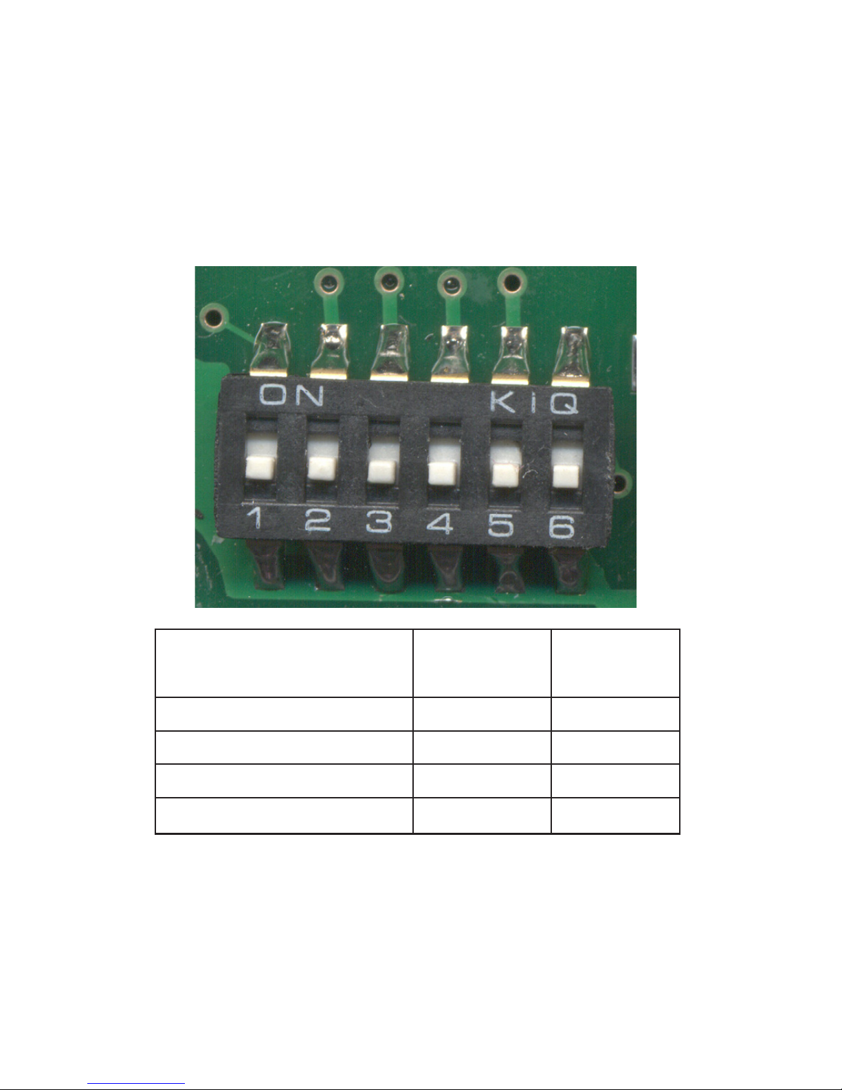
Pro Remote’ by means of the six position DIP
Program Switch.
There are two address functions, System Address
and Tool Address.

4 System Address
A System consists of an’ iVAC Pro Switch’ and
from one to eight iVAC Pro Tools or iVAC Pro
Remotes. There can be any mix of Tools or
Remotes.
By means of positions S1 and S2 of the DIP
Program Switch, the Remote can be assigned to
work on one of four System Addresses, A, B, C
or D.
The System Address enables up to four
Systems to operate independently while within
communication range of each other.
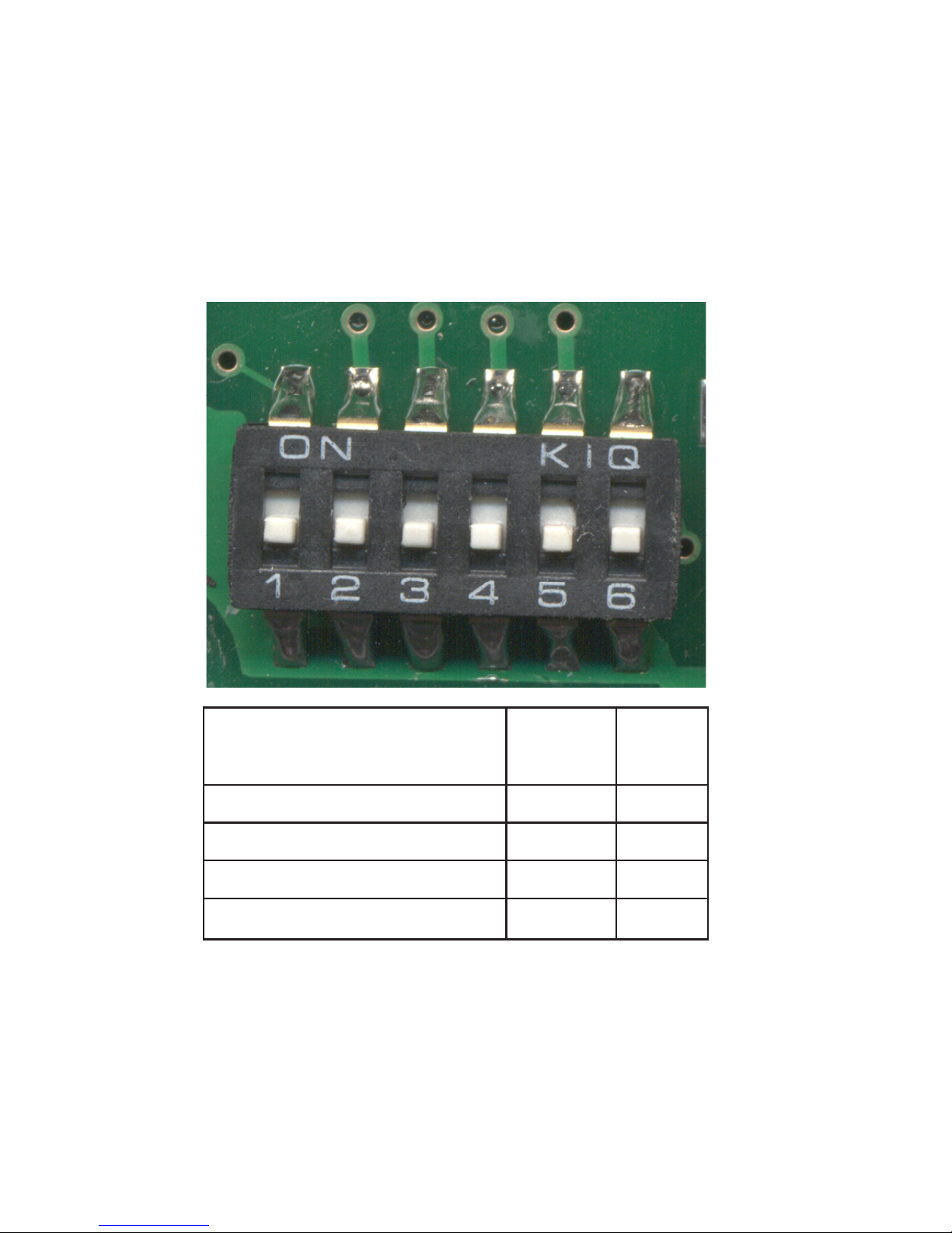
System Address
*factory setting
S1 S2
*A Off Off
B On Off
C Off On
D On On

5 Tool Address
Each iVAC Pro Remote or iVAC Pro Tool must
be assigned an independent one of eight Tool
Addresses. This information is used by the iVAC
Pro Switch to enable it to know the status of each
individual iVAC Pro Tool or iVAC Pro Remote in
the System. The Tool Address is set by means of
positions S3, S4 and S5 of the Program Switch.
S6 is not used.
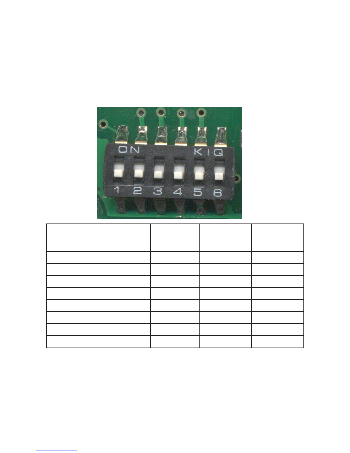
Tool Address
*factory setting
S3 S4 S5
1 On Off Off
2 Off On Off
3 On On Off
4 Off Off On
5 On Off On
6 Off On On
*7 On On On
8 Off Off Off

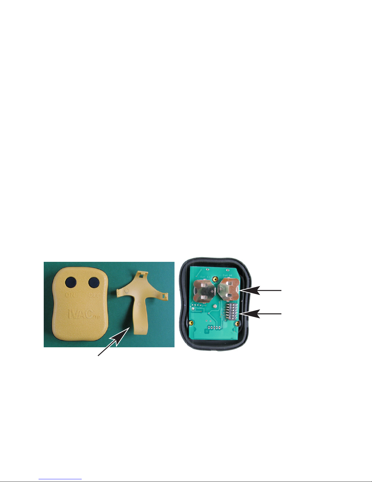
6 Replacing the Batteries
The batteries have a useful life of 25,000
operations over a 3 year period.
To remove the batteries it is recommended to use
the tip of a pen or similar device and push from
the inside edge of the battery holder.
When replacing CR2032 batteries, both batteries
should be replaced at the same time. The
positive (+) side of the battery should face away
from the circuit board.

7 Specications
Plastic housing ABS 94V0 plastic. Powered by 2
CR2032 lithium batteries. Rf Range 40 feet line of sight.
8 Regulatory Approval
This device complies with part 15 of the FCC rules.
Operation is subject to the following two conditions:
(1) This device may not cause harmful interference,
and (2) this device must accept any interference
received, including interference that may cause
undesired operation.
Caution: Changes or modications not expressly
approved by the party responsible for compliance
could void the user’s authority to operate the
equipment.
FCC ID: YCHIVACPRO IC 8940A-IVACPRO 10484-0000


GUIDE D’UTILISATION
DE LA TÉLÉCOMMANDE
iVAC PRO
www. switch.com
MBright Tools iVAC Inc.
5570 Jill Street
.
Box 557 . Osgoode, Ontario Canada . K0A 2W0
Tel: 613 826 2200
.
Fax: 613 826 3300 . info@iVacSwitch.com

Table des matières
1 Avertissements
2 Caractéristiques
3 Description
4 Adresse système
5 Adresse outil
6 Remplacement des piles
7Spécications
8 Approbation réglementaire
1 Avertissements
Prière de lire les directives de fonctionnement
avant d’utiliser. La télécommande iVAC Pro est
destinée à utilisation à l’intérieur dans les endroits
secs seulement. Les piles usées devraient être
éliminées de manière sûre.
2 Caractéristiques
Commutateur
de programme
DIP
Piles
Pince de ceinture

3 Description
La télécommande iVAC Pro fonctionne de concert
avec un commutateur iVAC Pro et permet de contrôler
à distance un collecteur de poussière au moyen d’une
intervention manuelle. Lorsque le bouton MARCHE
est enfoncé, une transmission par fréquence radio est
envoyée au commutateur iVAC Pro lui indiquant de
se mettre en marche et d’alimenter le collecteur de
poussière. Pour assurer un fonctionnement uniforme,
il est recommandé que les boutons soient enfoncéa
durant une ou deux secondes. La télécommande
iVAC Pro peut être programmée au moyen d’un
commutateur interne de programme DIP pour
fonctionner sur une des quatre adresses système et
une des huit adresses outil, similaire à un outil iVAC

Pro. (Se référer au Guide d’utilisation du système
iVAC Pro fourni avec le commutateur iVAC Pro.)
La télécommande iVAC Pro est intégrée dans un
boîtier de plastique de 80 mm x 70 mm x 24 mm.
Unepincedeceinturefacileàxerestégalement
fournie.Lecouverclearrièreestxépartroisvis.
Le retrait du couvercle permet l’accès aux piles
et au commutateur de programme DIP. Il est alors
possible de changer les piles et de programmer
les fonctions d’adresses de la télécommande
iVAC Pro au moyen du commutateur de
programme DIP à six positions.
Il existe deux fonctions d’adresse, une adresse
système et une adresse outil

4 Adresse système
Un système consiste en un commutateur iVAC
Pro et entre un et huit outils ou télécommandes
iVAC Pro. Il peut y avoir n’importe quel
agencement d’outils ou de télécommandes.
Par l’intermédiaire de positions S1 et
S2 du commutateur de programme DIP,
la télécommande peut être assignée à
fonctionnement sur une des quatre adresses
système, A, B, C ou D.
L’adresse système permet d’actionner jusqu’à
concurrence de quatre systèmes de façon
indépendante, à portée de communication l’un
de l’autre.
Adresse système
*réglage en usine
S1 S2
*A Arrêt Arrêt
B Marche Arrêt
C Arrêt Marche
D Marche Marche

5 Adresse outil
Chaque télécommande ou outil iVAC Pro doit
être assigné à une des huit adresses outil
indépendantes. Cette information est utilisée par
lecommutateuriVACPropouridentierlestatut
individuel de chaque outil ou télécommande iVAC
Pro dans le système. L’adresse outil est réglée au
moyen ds positions S3, S4 et S5 du commutateur
de programme. S6 n’est pas utilisé.

Adresse outil
*Réglage en usine
S3 S4 S5
1 Marche Arrêt Arrêt
2 Arrêt Marche Arrêt
3 Marche Marche Arrêt
4 Arrêt Arrêt Marche
5 Marche Arrêt Marche
6 Arrêt Marche Marche
*7 Marche Marche Marche
8 Arrêt Arrêt Arrêt

6 Remplacement des piles
Les piles ont une vie utile de 25 000 opérations
sur une période de 3 ans.
Pour retirer les piles, il est recommandé d’utiliser
la pointe d’un crayon ou d’un dispositif similaire
et de pousser en partant de la bordure intérieure
du compartiment des piles.
Lors du remplacement des piles CR2032, les
deux piles doivent être remplacées en même
temps. La borne positive (+) de la pile devrait être
du côté opposé de la carte de circuit.

7 Spécications
Boîtier de plastique ABS94V0 alimenté par 2 piles au lithium
CR2032. Portée de fréquence radio : 40 pieds à vue.
8 Approbation réglementaire
Le présent appareil est conforme aux CNR d’Industrie
Canada applicables aux appareils radio exempts de licence.
L’exploitation est autorisée aux deux conditions suivantes :
(1) l’appareil ne doit pas produire de brouillage, et (2)
l’utilisateur de l’appareil doit accepter tout brouillage
radioélectrique subi, même si le brouillage est susceptible
d’en compromettre le fonctionnement.
Attention : les changements ou modications non
expressément approuvés par la partie responsable de la
conformité pourraient annuler le pouvoir de l’usager de
faire fonctionner l’équipement.
FCC ID: YCHIVACPRO IC 8940A-IVACPRO 10484-0000

GUÍA DE UTILIZACIÓN
DEL TELEMANDO
iVAC PRO
www. switch.com
MBright Tools iVAC Inc.
5570 Jill Street
.
Box 557 . Osgoode, Ontario Canada . K0A 2W0
Tel: 613 826 2200
.
Fax: 613 826 3300 . info@iVacSwitch.com

Indices del contenido
1 Advertencias
2 Característicos
3 Descripción general
4 Dirección de sistema
5 Dirección de herramienta
6 Reemplazo de pilas
7Especicaciones
8 Aprobación de regulación
1 Advertencias
Leer las instrucciones de funcionamiento antes de
utilizar.
El telemando iVAC Pro está destinado a un uso
interior en lugares secos solamente. Las pilas
gastadas deben ser eliminadas de manera segura.
2 Característicos
Pince de ceinture
Conmutador
de programa
DIP
Pilas

3 descripción general
El Telemando iVAC Pro funciona conjuntamente
con el conmutador iVAC Pro y permite de controlar
a distancia un colector de polvo por medio de una
intervención manual. Cuando el botón MARCHA
está hundido, una transmisión por frecuencia
de radio está enviada al conmutador iVAC Pro
indicándole de ponerse en marcha y alimentar al
colector de polvo.
Cuando el botón PARO está hundido, la corriente
estará retirada del colector de polvo.
Para asegurar una operación consistente, se
recomienda que los botones estén hundidos
durante uno o dos segundos. El Telemando iVAC
Pro puede ser programado por medio de un
conmutador interno de programa DIP para funcionar

sobre uno de las cuatro direcciones de Sistema
y una de los ocho direcciones de Herramientas,
parecido a un Herramienta iVAC Pro. (Referirse
a la guía de utilización del Sistema iVAC Pro
proporcionada con el conmutador iVAC PRO).
El telemando iVAC Pro está integrado en una
caja de plástico De 90mm x 70mm x 25mm. Una
pinzadecinturónfácildejarestáigualmente.
proporcionada. La tapa trasera está sujetada con
tres tornillos. El retiro de la tapa trasera permite el
acceso a las pilas y al conmutador del programa DIP.
Entonces se puede cambiar las pilas y programar las
funciones de dirección del telemando iVAC Pro por
medio de un conmutador de programa DIP de seis
posiciones. Existen dos funciones de dirección, una
dirección de sistema y una dirección de herramienta.

4 dirección de sistemas
Un sistema consiste en un conmutador iVAC Pro
y de uno a ocho Herramientas o Telemandos
iVAC Pro. Puede haber cualquier combinación de
Herramientas o de Telemandos. Por medio de las
posiciones S1 y S2 del conmutador de programa
DIP, el Telemando puede ser programado para
funcionar sobre uno de las cuatro direcciones de
sistemas, A, B, C, o D.
La Dirección de Sistema permite accionar hasta
una concurrencia de cuatro Sistemas de manera
independiente, al alcance de una comunicación
del uno al otro.

Dirección de sistemas
*Arreglo de Fàbrica
S1 S2
*A Paro Paro
B Marcha Paro
C Paro Marcha
D Marcha Marcha

5 Dirección de herramienta
Cada telemando o herramienta iVAC Pro debe ser
asignado a una de las ocho direcciones
de herramienta independientes. Esta información
está utilizada por el conmutador iVAC Pro
paraidenticarelestatutoindividualdecada
herramienta o telemando iVAC Pro en el sistema.
La dirección de herramienta está arreglada por
medio de las posiciones S3, S4 y S5 del
conmutador de programa. S6 no está utilizado.

Dirección de
herramienta
*Arreglo en Fábrica
S3 S4 S5
1 Marcha Paro Paro
2 Paro Marcha Paro
3 Marcha Marcha Paro
4 Paro Paro Marcha
5 Marcha Paro Marcha
6 Paro Marcha Marcha
*7 Marcha Marcha Marcha
8 Paro Paro Paro

6 Reemplazo de las pilas
Las pilas tienen una vida útil de 25,000
operaciones sobre un período de 3 años. Para
retirar las pilas, se recomienda de utilizar la punta
de un lápiz o un dispositivo similar y de empujar
partiendo del borde interior del compartimento
de las pilas.
Al momento de reemplazar las pilas CR2032,
las dos pilas deben ser reemplazadas al mismo
tiempo. El borne positivo (+) de la pila debería
estar al lado opuesto de la tarjeta del circuito.

7 Especicaciones
La caja de plastic ABS94V0. Alimentada por 2 pilas de litio
CR2032. Alcance de la frecuencia radio: 40 pies a la vista
8 Aprobación reglementaria
Este aparato es conforme a la parte 15 de los
reglamentos FCC. El funcionamiento
depende de las dos condiciones siguientes:
(1) Este aparato no puede causar interferencias
perjudiciales y (2) este aparato debe aceptar toda
interferencia pudiendo causar un funcionamiento no
deseado.
Cuidado: Los cambios o modicaciones que no
han sido aprobados por la parte responsable de la
conformidad, podrían anular el poder del usuario de
hacer funcionar el equipamiento.
FCC ID: YCHIVACPRO IC 8940A-IVACPRO 10484-0000

 Loading...