


ITX系列
用户手册
你现选用的产品型号为:
ITX-M4S1L7
ITX-M4S1LA
ITX-M4S2GAP
ITX-NG81-DG
Rev:1.1
Date:2008.12
1
安全指导
01. 务必请仔细通读本安全指导.
02. 务必请妥善保管本手册,以备将来参考.
03. 请保持本设备的干燥.
04. 机箱的开口缝隙是用于通风避免机箱内的部件过热,请勿将此类开口掩盖
或堵塞.
05. 在将本设备与电源连接前,请确认电源电压值,将电压调整为110V/220V.
06. 请将电源置于不会被践踏到的地方,并且不要在电源线上堆置任何实物.
07. 插拔任何扩展卡或设备模块前,请将电源线拔下.
08. 请留意手册上提到的所有注意和警告事项.
09. 通电之前请确认主机箱中不要遗留螺丝等金属物件,以免电气短路烧毁其
他部件.
10.不得将任何液体倒入机箱开口的缝隙中,否则会产生严重损坏或电路瘫痪.
11.如果发生以下情况,请找专业人员处理:
v 电源线或插头损坏
v 液体渗入机器内
v 机器暴露在潮湿的环境中
v 机器工作不正常或用户不能通过本手册的指导使其正常工作
v 机器跌落或受创
v 机器有明显的破损迹象
目录
安全指导......................................................................2
商标声明......................................................................2
第一章 主板简介及规格说明.............................................4
1.1 包装盒内物品清单.........................................................................................4
1.2 主板LAYOUT 图及规格表............................................................................5
第二章 硬件设备的安装说明.............................................18
2.1 中央 处理器的安装........................................................................................18
2.2 CPU风扇的安装........................................................................................19
2.3 内存 的安装...................................................................................................21
2.4 主 板跳线的设定说明.....................................................................................22
2.5 主 机 板 接 头 说 明.............................................................................................23
第三章 BIOS 简介..........................................................31
3.1 BIOS升级更新..............................................................................................31
3.2 BIOS设定.....................................................................................................31
3.3 BIOS语言切换..............................................................................................32
商标声明
所有的品牌,产品,徽标,商标和公司名称都是属于商标或注册商标各自的拥
有者。
AMI®是 AMI 公司的注册商标。
Intel® ,Celeron® ,Pentium®是 Intel 公司的注册商标。
Netware®是 Novell Inc.的注册商标。
PS/2 和 OS/2 是 International Business Machines 公司的注册商标。
Windows®98/ 2000/NT/XP 和 Microsoft®是 Microsoft 公司的注册商
标。
第四章 驱动程序的安装..................................................33
4. 1 芯片组驱动程序的安装...............................................................................33
4. 2 板载显卡驱动的安装...................................................................................33
4. 3 板载网卡驱动的安装...................................................................................33
4. 4 板载声卡驱动的安装...................................................................................33
4. 5 USB2. 0驱动程序的安装............................................................................33
32

第一章 主板简介及规格说明
谢谢您采用了我司的 ITX 系列主板,为了保证产品品质并适合市场需
求,主板都通过了抗老化、低电压、各种温度、湿度环境下的反复测试,
均能满足行业的需求。是兼顾性价比、稳定、寿命长的高规格主流平台解
决方案,同时为了兼顾大部份海内外市场,我们专门提供了中英文两种语
言的BIOS。本手册主要介绍了产品的规格参数及安装主板的步骤。需要更
加详细的主板 BIOS 设置信息可参看驱动光盘中的 BIOS 设置用户手册。
由于主板规格和 BIOS 软件将不断更新,本手册之相关内容变
更恕不另行 通知,一切仅供参考,请以实际为准或留意网上公
布的升级版本.
1.1 包装盒内物品清单
v ITX-M4S1L7/ITX-M4S1LA/ITX-M4S2GAP/ITX-NG81-DG 主板
v 80-Conductor Ultra ATA 66/100 IDE 数据线
v SATA 数据线
v 用户手册 -- 选配
v 驱动光盘
v 质保卡
v 合格证
v 挡板
1.2 主板 LAYOUT 图及规格表
ITX-M4S1L7
54

ITX-M4S1L7 主板规格如下表:
处理器 --支持533/800/1066MHz前端总线
D系列
®
CoreTM2 Quad
--支持 LGA 775 Intel
6000 系列/CoreTM 2 Duo E6000 系列
/CoreTM 2 DUO E4000 系列/Pentium
Dual-core E2000 系 列/Celeron
Dual-core E1000 系列/Celeron® 400 系
列/Pentium® D系列/Pentium
/Celeron
芯片组
内存 --支持 DDRII533/667 内存.
板载显卡
板载声卡
板载网卡
存储标准 --2 个 SATA 3GB/s 接口,
扩展槽
USB 接口
--北桥:Intel® 945GC
--南桥:Intel® ICH7
--最大容量支持 2GB
--内存插槽 1*DDR2 DIMM
--集成 GMA950 显示核心,支持 DX9.0C
--集成 ALC 655 声卡芯片
--支持 2/4 声道输出
--集成 Realtek 8101E 10/100M 自适应网卡芯
片,支持无盘
--1 个 IDE 接口,可扩接 2 个设备,
--1 个 MINI IDE 接口
--1 个 PCI 插槽
--4*USB 2.0 接口(2 个后面版板载,2 个扩展)
®
®
4 系列
内部输入/出接口 --1 个 24 PIN 主电源接口
--1 个 4PIN 12V 电源接口
--2 个 SATA 3GB/s 接口
--1 个 CPU 风扇接口、1 个系统风扇接口
--1 组前面版插针
®
®
--1 个前置声卡插针
--1 组 USB 2.0 接口
--3 个 COM 插针
--1 个清除 CMOS 插针
--1 个 IDE 接口
--1 个 MINI IDE 接口
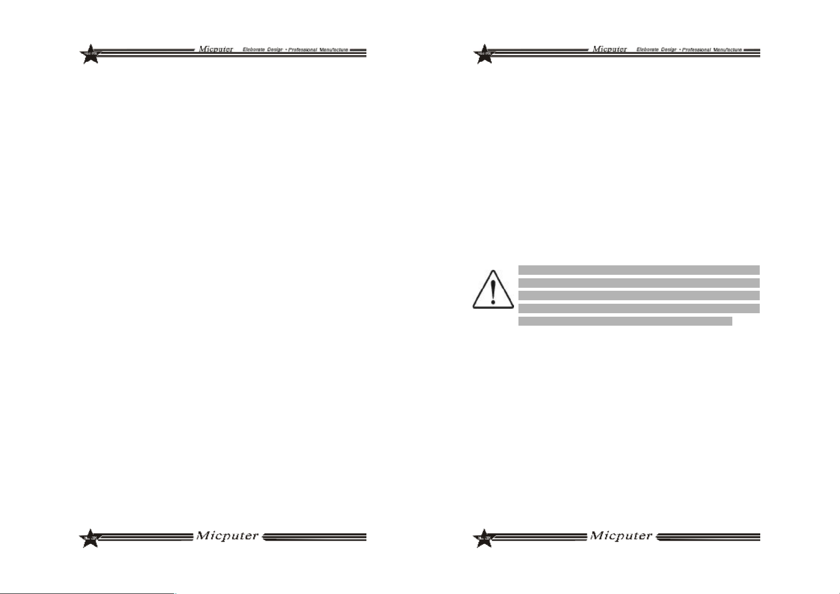
后面板接口 --1 个 PS/2 键盘接口
--1 个 PS/2 鼠标接口
--1 个 COM 接口
--1 个 VGA 接口
--2 个 USB 接口
--1 个 RJ45 接口
--一个打印接口
--2*JACK 接口
输入/输出控制器
--ITE8712F-S
硬件监测功能 --CPU 温度监控
--系统温度监控
--风扇转速监控
--各电压监控----可选
BIOS
--1*4Mbit flash
--提供中英文双语言 BIOS 界面
主板结构及尺寸
--ITX 170mm x 170mm
76
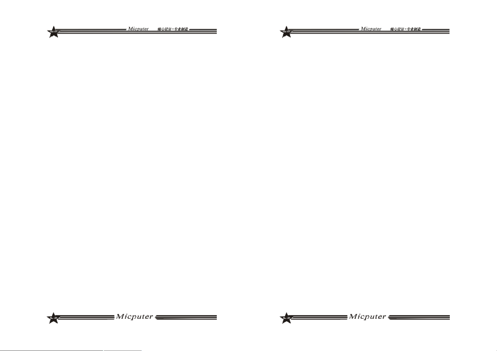
ITX-M4S1LA 主板规格如下表:
ITX-M4S1LA
处理器
芯片组
内存
板载显卡
板载声卡
板载网卡
存储标准 --2 个 SATA 3GB/s 接口,
扩展槽
USB 接口
板上自带 Intel
器
--北桥:Intel® 945GC
--南桥:Intel® ICH7
--支持 DDRII533/667 内存.
--最大容量支持 2GB
--内存插槽 1*DDR2 DIMM
--集成 GMA950 显示核心,支持 DX9.0C
--集成 ALC 655 声卡芯片
--支持 2/4 声道输出
--集成 Realtek 8101E 10/100M 自适应网卡芯
片,支持无盘
--1 个 IDE 接口,可扩接 2 个设备,
--1 个 MINI IDE 接口
--1 个 PCI 插槽
--8*USB 2.0 接口(2 个后面版板载,6 个扩展)
®
AtomTM230/330 系列处理
98

内部输入/出接口 --1 个 24 PIN 主电源接口
--1 个 4PIN 12V 电源接口
--2 个 SATA 3GB/s 接口
--1 个 CPU 风扇接口
--1 组前 面版插针
--1 个前置声卡插针
--3 组 USB 2.0 接口
--3 个 COM 插针;1 个打印头插针
--1 个清 除 CMOS 插针
--1 个 IDE 接口;1 个 MINI IDE 接口
--1 组 IR 插针;1 组 VGA-H 插针
后面板接口 --1 个 PS/2 键盘接口
--1 个 PS/2 鼠标接口
--1 个 COM 接口
--1 个 VGA 接口
--1 组 TV/AV 接口
--2 个 USB 接口
--1 个 RJ45 接口
--3*JACK 接口
输入/输出控制器 --ITE8712F-S
硬件监测功能
BIOS
主板结构及尺寸
--CPU 温度监控
--系统 温度监控
--风扇 转速监控
--各电压监控----可选
--1*4Mbit flash
--提供 中 英文双语言 BIOS 界面
--ITX 170mm x 170mm
ITX-M4S2GAP 正面图
1110

ITX-M4S2GAP 主板规格如下表:
ITX-M4S2GAP 背板图
处理器 1. 板上自带 Intel
芯片组
内存
显卡 1. 板载 GMA 950 显示核心,支持 DirectX 9.0C
声卡
网卡 1. 板载 Realtek 8111C 双千兆网卡,支持 10/100/1000M 网络传输
存储标准
扩展槽
USB 1. 支持 7 个 USB 2.0 端口 (3 个需要扩展)
后面板接口 1. 1 个 PS/2 鼠标端口, 1 个 PS/2 键盘端口
I/O 1. ITE8712F-S 双 IO
1. 北桥:Intel
2. 南桥:ICH7M
1. 支持 DDRII533 笔记本内存
2. 最大容量支持 2GB
3. 内存插槽 1*DDR2 SODIMM
1. 板载 Realtek ALC655 音效解码芯片
2. 支持 2/4 声道输出
1. 2*SATA 3 Gb/s 磁盘接口
2. 1 个 44pin IDE 磁盘接口
1. 1 个 PCI 插槽
2. 1 个 VGA 端口
3. 1 个 S 端子
4. 4 个 USB 2.0 端口
5. 2 个 RJ-45 网卡端口
6. 2 JACK 音频接口(4声道音频接口)
®
AtomTMN270 系列处理器
®
945GSE
1312
内部输入/出
接口
硬件监测功
能
BIOS 1. 1*8Mbit flash
主板结构及
尺寸
1. 1 个 24-pin ATX 主电源接口
2. 1 个 DC 电源接口
3. 1 个 IDE_PWR 辅助电源接口
4. 1 个 MINI IDE 接口
5. 2 个 SATA 磁盘接口
6. 1 全 CPU 风扇接口
7. 1 个系统风扇接口
8. 1 组前置音频跳线插针
9. 3 个 USB 扩展插针接口
10. 1 组红外接口插针
11. 1 组 CMOS 清除跳线插针
12. 1 组 J3V 插针
13. 1 组 P12V 插针
14. 1 组 J5VSB 插针
15. 1 组 J5V 插针
16. 1 组 VGA_H 插针
17. 1 组 TV_OUT_H 插针
18. 4 个 COM 扩展插针
19. 1 组打印端口插针
20. 1 组 RI_PWR 插针
21. 1 组 LVDS 插针
22. 1 组 LVDS_PWR 插针
23. 1 组 INVERT 插针
24. 1 组前置面版插针
1. CPU 温度监控
2. 系统温度监控
3. 风扇转速监控
4. 各电压监控----可选
1. ITX 170.00mm x 170.00mm
ITX-NG81-DG
1514

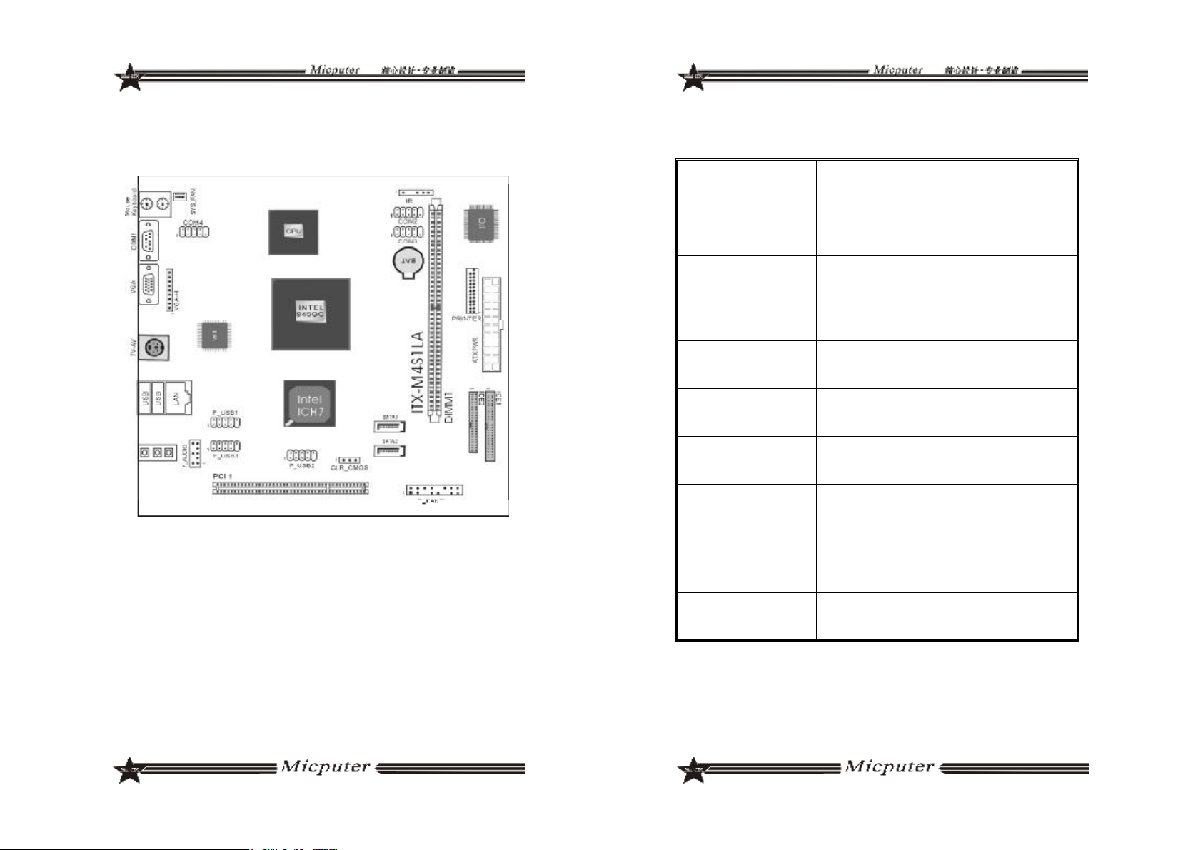
ITX-NG81-DG 主板规格如下表:
1. AMD AM2 Athlon64 x2/Athlon64/Sempron 处理器
2. AMD Socket AM2+ Phenom FX / Phenom X4 / Phenom X2 系列处理
处理器
芯片组 1. nVIDIA MCP78V 单芯片
内存
显卡 1. 板载 GeForce8100 显示核心,支持 DirectX 10
声卡
网卡 1. 板载 Realtek 8111C 双千兆网卡,支持 10/100/1000M 网络传输
存储标准
扩展槽
USB 1. 支持 6 个 USB 2.0 端口 (2 个需要扩展)
器
3. HyperTransport 3.0 总线,支持 AM2+ K10 CPU
4. HyperTransport 1.0 总线,支持 AM2 K8 CPU
1. 支持 DDRII533/667/800 内存
2. 最大容量支持 2GB
3. 双通道内存 支持
4. 内存插槽 2*DDR2 SODIMM
1. 板载 Realtek ALC883 音效解码芯片
2. 支持 2/4/5.1/7.1 声道输出
1. 4*SATA 3 Gb/s 磁盘接口
2. 1 个 40pin IDE 磁盘接口
1. 1 个 PCI 插槽
内部输入/出
接口
后面板接口 1. 1 x PS/2 鼠标端口, 1 x PS/2 键盘端口
I/O
硬件监测功
能
BIOS 1. 1*8Mbit flash
主板结构及
尺寸
1. 1 个 24-pin ATX 主电源接口
2. 1 个 4-pin ATX 电源接口
3. 1 个 IDE 接口
4. 4 个 SATA 磁盘接口
5. 1 个 CPU 风扇接口
6. 1 个系统风扇接口
7. 1 组前置音频跳线插针
8. 1 组 USB 扩展插针
9. 1 组 SPDIF 音频插针
10. 1 组 COM 扩展插针
11. 1 组清除 CMOS 插针
12. 1 组前面版插针
2. 1 x DVI 端口,1 x VGA 端口,1 x HDMI 端口
3. 4 x USB 2.0 端口
4. 2 x RJ-45 网卡端口
5. 6 JACK(八声道音频接口)
1. ITE8712F-S
1. CPU 温度监控
2. 系统温度监控
3. 风扇转速监控
4. 各电压监控----可选
1. ITX 170.00mm x 170.00mm
1716

第二章 硬件设备的安装说明
2.1 中央处理器的安装
要安装 Intel775 针CPU,请按下面的步骤操作
在你将 775 针 CPU 插入插槽之前,请检查 CPU 表面是否不洁
~
或者插槽上是否有歪斜的针脚。如果发现以上情形,切勿强
行将 CPU 插入插槽。否则 CPU 或插槽将会严重受损。
步骤一 将主板 CPU 插座侧边的固定拉杆拉起,转动拉杆至大约135 度
的完全打开位置,然后转动承载上盖至大约100 度的完全打开位
置。
步骤三 卸下 CPU 保护盖,确认主机板上特别设计的 Socket 底座的 2
个凸出位置及 CPU 的 2 个定位凹口位置方向对准后,将 CPU 轻
轻平放置入 Socket 中,如果两者方向未对准 CPU 将无法置入
Socket 中。请注意避免让 CPU 歪斜而造成针脚损坏。
步骤四 CPU 放置好后,盖回承载上盖,将拉杆压回,将承载上盖卡
入拉杆的固定卡舌之下,固定住拉杆,CPU 的安装即完成。
步骤二 去除承载上盖的防护盖,用你的左手食指和拇指扶着承载金属
框边缘,用右手拇指揭开防护盖便使它脱离插槽,同时按压防护
盖的中央部分助力移除。
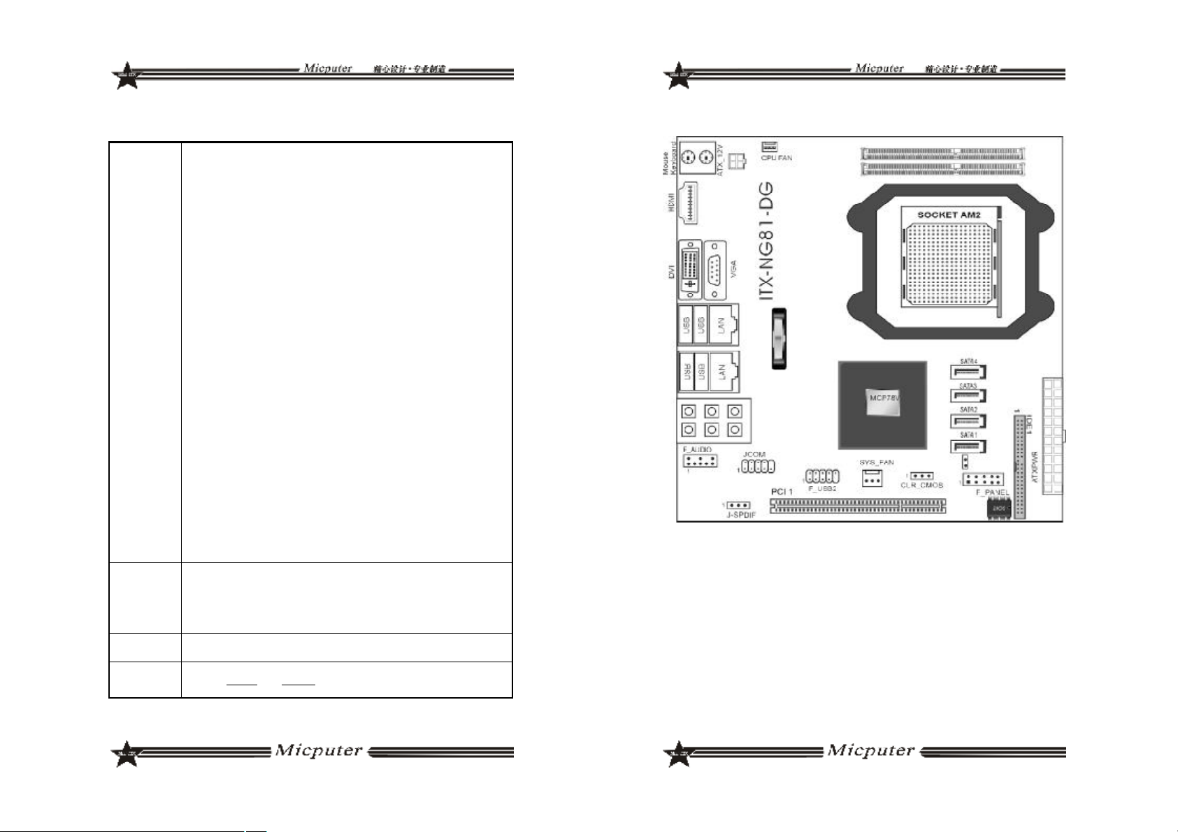
2.2 CPU 风扇的安装
为了 CPU 能正常工作,必须选用散热性能得到保证的散热器。这
里我们以 Intel 的原装风扇为例,说明CPU 风扇的安装过程。
步骤一 在安装风扇前检查一下风扇散热片底部是否涂有散热膏[Intel 的
原装风扇上一般带有导热材料 TIM],如果您的风扇散热片底部没
有导热材料,请在安装前在 CPU 上表面涂上适量散热膏。
1918
步骤二 请先卸下风扇电源线,将四个扣环的缺口转向内。
步骤三 确保将风扇电缆放在最靠近主板风扇电源插头的一侧,将散热
器放在 LGA775 插座上,将四个扣件对准主板上的四个通孔,然
后将散热器上的四个扣件按下扣紧。
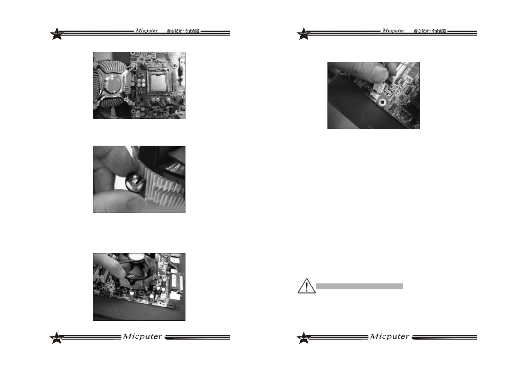
步骤四 将风扇电源线接口插在主机板上标有“CPU FAN”的四线排
针处。
2.3 内存的安装
2.3.1 DIMM 内存条的安装
主机板支持 DDRII 内存,容量可从最小的 64MB 扩展至最大 2GB。
安装步骤如下:
a. 将内存槽两端的白色卡榫向外扳开。
b. 将内存条有金手指的那边对准内存槽,注意内存条的凹孔要对应插槽
的凸起点。
c. 将内存条插入插槽中。若安装正确则插槽两端的白色卡榫会因为内存
条置入而自动卡 紧,否则不会卡紧。
2.3.2 SODIMM(笔记本)内存条的安装
主机板支持 DDRII SODIMM 内存,容量可从最小的 64MB 扩展至最大 4GB
不等,具体安装步骤如下:
a.将内存条的金手指以 45 度角度放入内存槽中
b.然后稍微用力按下内存条至与内存槽卡扣平行位置,此时卡扣会自动卡
紧内存条。
为了使系统稳定,请选用正牌内存。
2120

2.4 主板跳线的设定说明
主板上的所有跳线靠近直线或标有粗白线或白色三角符处为第一脚,
请务必不要接反,否则有可能对您的主机板或其他设备造成损坏。
2.4.1 清除 CMOS 跳线(CLR_CMOS)
如果主机板因为 BIOS 设置错误而出现问题,此时可清除 CMOS 解
决问题;方法是在断开电源状态下把 CMOS 跳线跳至 2-3 脚,使其短接 5-
6 秒。请不要在开机时清除 CMOS,要不然可能会损坏您的主板。跳线设
定如下:
2.4.2 LVDS 电源跳线(LVDS_PWR)
2.5 主机板接头说明
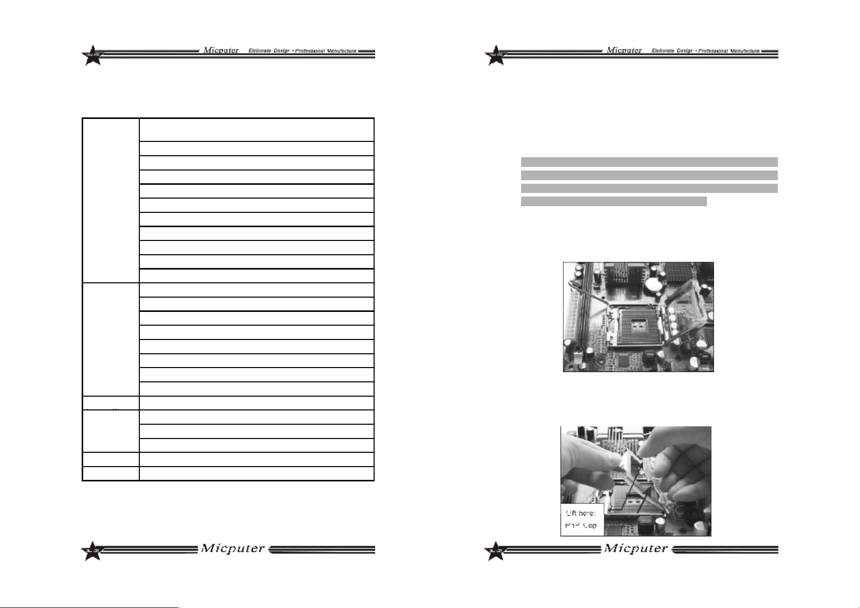
2.5.1 风扇电源接头(CPU_FAN1/SYS_FAN1)
当将风扇连接到风扇连接头上时,使用者必须将红色的线连接到
+12V 的电源针上,黑色的线连接到地线上。如果您想在 BIOS 或硬件监控
程序中观察风扇的工作状态,您必须使用支持能侦测转速功能的风扇。对
于具有速度感应器的风扇,风扇每一次转动都会产生 2 个脉冲波,系统硬
件监控将作统计逼供内产生一个风扇转动速度的报告,可在 CMOS 中显示
出风扇的转速。
设置状态
3.3V 可用(预设)
5V 可用 跳至 1-2 脚
2.4.3 DC 与 ATX 电源切换跳线(J5V/J5VSB/P12V/J3V)
状态
使用 ATX 电源(预设) 4 组跳帽全跳 2-3 脚
使用 DC 12V 电源 4 组跳帽全跳 1-2 脚
J5V J5VSB P12V J3V
LVDS_PWR
跳至2-3 脚
2.5.2 USB 扩展接头
主板提供多个USB 接口,其中有些可以直接连接USB 设备,F_USB1/
F_USB2/F_USB3 等连接头需要另外连接 USB Cable,提供给您另外几组
USB 端口,您能从主板经销商或电子市场上购买到此种USB Cable 连接
线。(粗白线或小三角形处为第一脚,请务必不要接错,否则有可能对您
的主板或设备造成损害)
插针旁的粗白线或“△”标识处为第一脚,请务必不要接
~
错,否则有可能对您的设备或主板造成损害!
2322

2.5.3 前置音效输出接口(F_AUDIO)
主板提供了前置音效输出接口 F_AUDIO,这组声卡插针供您连
接到机箱前面板的声卡接头,这样您就可以很方便地经由主机到面板
收听音乐和使用麦克风进行声音输入,您只要按照其插针功能(如
下图所示)连接相对应的线即可。
2 10
1
9
PIN1: Mic in(麦克风输入信号)
PIN2: Aud GND(模拟音频线路接地)
PIN3: Mic VREF(麦克风电源)
PIN4: Void(没连接)
PIN5: FPOUT R(右声道声音信号输出)
PIN6: RET R(右声道声音信号返回)
PIN7: KEY(RSVD耳机备用)
PIN8: Void(没连接)
PIN9: FPOUT L(左声道声音信号输出)
PIN10: RET L(左声道声音信号返回)
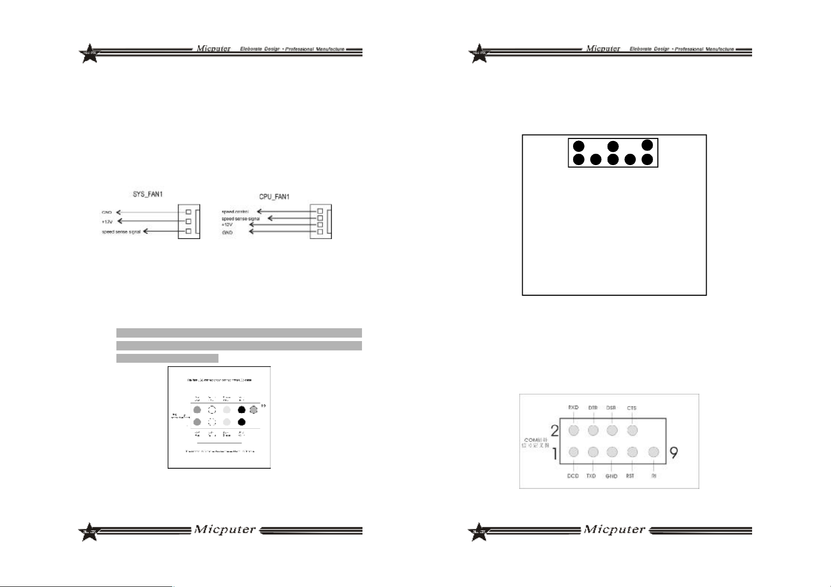
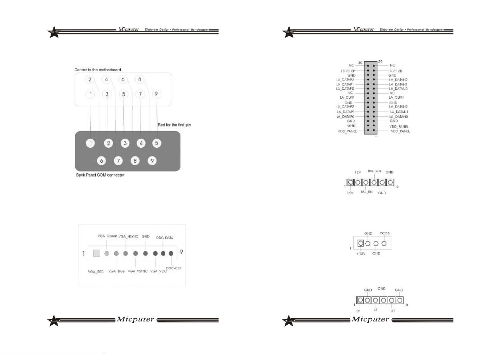
2.5.4 COM 插针(COM1/COM2/COM3/COM4)
主机板提供几个COM 插针,其连接头需要另外连接 COM 连接线,
您能从主板经销商或电子市场上购买到此种 COM 连接线。(白三角形标
记处为第一脚,请务必不要接错,否则有可能对您的主板或设备造成损
害)
2.5.5 COM 插针的接线方法
若要使用 COM 插针,必需通过转接线来实现,转接线的接线方法如下:
2.5.6 VGA 接口(VGA_H)
主机板提供了 1 个非标准的 VGA 接口,其信号定义图如下所示:
2524

2.5.7 LVDS 接口(LVDS)
主机板提供了 1 组 LVDS 插针,其信号定义图如下所示:
2.5.8 INVERT 接口(INVERT)
主机板提供了 1 组 INVERT 插针,其信号定义图如下所示:
2.5.9 IDE_PWR 接口(IDE_PWR)
主机板提供了 1 组 IDE_PWR 电源接口,其信号定义图如下所示:
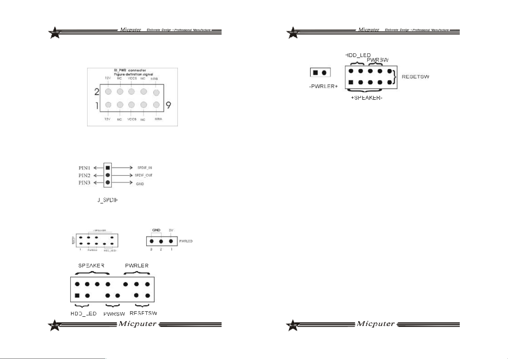
2.5.11 RI_PWR 接口(RI_PWR)
主机板提供了 1 组 RI_PWR 插针,其信号定义图如下所示:
2.5.12 SPDIF 接口(J_SPDIF)
主机板提供了 1 组SPDIF 插针,支持数字音频输入 / 输出功能, 其信号
定义图如下所示:
2.5.13 系统信号 / 控制面板接口(F_PANEL)
ITX-M4S1L7面板接口
2.5.10 TV_ OUT_H 接口(TV_OUT_H)
主机板提供了 1 组 TV_OUT_H 插针,其信号定义图如下所示:
ITX-M4S1LA/M4S2GAP 面板接口
2726
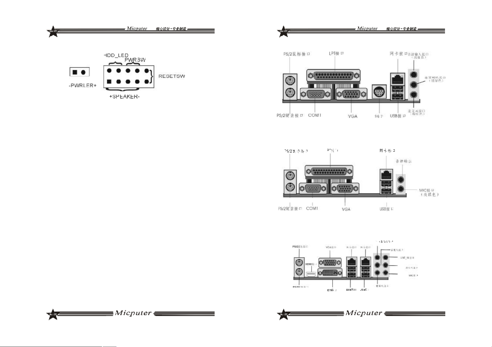
ITX-NG81-DG 面板接口
a.SPEAKER 喇叭连接头
b.PWRLED 电源指示灯
c.HD_LED 硬盘指示灯连接头
d.PWRSW ATX 电源开关
e.RESETSW 复位按钮
v SPEAKER 喇叭连接头
电脑的喇叭连接头(也称蜂鸣器)共有四个脚位,只要把机箱上的喇叭接头
接至此四脚位上即可使用。
v PWRLER 电源指示灯
电源指示灯为三个脚位的连接头,用来指示电脑的工作状态,当电脑一
旦上电时,指 示灯常亮 ,反之,则不亮( 注:有正负之分) 。
v HDD_LED 硬盘指示灯连接头
这组两脚位排针连接到电脑机箱上的硬盘指示灯接头上,可由LED 以显
示硬盘工作的状态,如果硬盘一旦有读取动作,指示灯随即亮起(注:有
正 负 之 分 )。
v PWRSW ATX 电源开关
POWER SW 是一个两针脚的接头,控制着 ATX 主电源的总开关,将这
组排针连接到电脑机箱上控制电脑电源的开关上,当两个针脚短接即可开
( 关 ) 机。
v RESET SW 复位按钮
这组两脚位排针接到电脑机箱上的 RESET 开关,可让您不需要关掉电脑电
源即可重新启动系统,尤其在系统挡机或死机时特别有用。
2.5.14 主板后面板接口说明
ITX-M4S1LA 后面板接口
ITX-M4S1L7 后面板接口
ITX-NG81-DG 后面板接口
2928

ITX-M4S2GAP 后面板接口
第三章 BIOS 简介
3.1 BIOS 升级更新
为了满足客户的需要,我们特提供 WINDOWS 及 DOS 两个系统的
BIOS 刷新工具,具体操作方法如下
3.1.1 DOS 下刷写方式
a. 刷新工具:AFUDOS.EXE
b. 刷新方法:准备一张 DOS 启动盘,只含三个最基本的 DOS 启动文件
即可,将 AMI BIOS 刷新工具和 BIOS 文件拷贝到这张软盘 /U 盘根目录
下,使用此软盘 /U 盘开机引导系统,进到 DOS 后输入 AFUDOS 空格
BIOS文件名空格 /P 空格/B 空格/N 空格/C 空格/X 回车,此时进行BIOS
刷写过程,当刷写完毕后会有相关提示时,此时才可重启电脑,按 F1 键
进入 CMOS 设置,选择 Load Optimal Defaults
3.1.2 WINDOWS 下刷写方式
a.刷新工具:AFUWIN.EXE
b.刷新方法:在 WINDOWS 下运行 AFUWIN.EXE--- 点击OPEN--- 选择要
对应的 BIOS 文件 --- 勾选 Program ALL Blocks 后点击FLASH,此时进
行刷写 BIOS 过程,刷写过程中键盘鼠标为锁定状态,当刷写完成后键
盘鼠标恢复使用,此时重启电脑按 F1 键进入 CMOS 设置,选择 Load
Optimal Defaults
BIOS 刷写存在风险,请在专人指导下进行刷写,并留意以下两点:
1.BIOS 文件要与实际产品型号相符
2.BIOS 在刷写过程中请勿非法关机 / 重启电脑
3.2 BIOS 设定
请注意由于 BIOS 的不断更新,可能我们说明的部分或许与现有板上
BIOS 有些不同,一切仅供参考,以实际为主。BIOS 中一些未做过多说明
的项目,属于非常用项目请保持缺省值,建议不要随意更改。
欲进入 BIOS 设定程序画面,请依下列步骤:
a. 打开电源或重新启动系统,在自检画面可看到“PRESS DEL TO RUN
SETUP”
b. 按下 DEL 键后,即可进入 BIOS 设定程序。
3130

3.3 BIOS 语言切换
为了让更多的用户能够熟悉并对 BIOS 操作,我们特别推出中文和英
文两种语言 BIOS,用户只需要进入 CMOS 后按“F5”就可以轻松进行中
文和英文 BIOS 之间的切换,让 BIOS 操作不再神秘。
第四章 驱动程序的安装
该板支持 WINDOWS2K 及以上系统,各系统软件不一,我们附带
光盘里提供 2K/XP/VISTA 系统的驱动,现安装说明仅以 M4S1L7 2K/XP 系
统为例
4. 1 芯片组驱动程序的安装
a. 进入驱动光盘 MB\INF 目录,鼠标左键双击 "945INF. exe".
b. 鼠标点击安装界面上 " 下一步 " 按钮.
c. 点击 " 是",再点击 " 下一步 ".
d. 安装完成后,在重新启动选项中选择 " 是 " 然后按" 完成" 重新启动计算机,
之后驱动程序自动加载.
4. 2 板载显卡驱动的安装
a. 进入驱动光盘 MB\VGA\945 目录,鼠标左键双击 "WIN2k_xp1417.
exe".
b. 鼠标点击安装界面上 " 下一步 " 按钮.
c. 点击 " 是",再点击 " 下一步 ".
d. 安装完成后,在重新启动选项中选择 " 是 " 然后按" 完成" 重新启动计算机,
之后驱动程序自动加载.
4. 3 板载网卡驱动的安装
安装 XP 系统时只需在 " 系统属性 " 下,选择 " 硬件 ",打开设备管理器,更新网
卡的驱动程序即可.
4. 4 板载声卡驱动的安装
a. 进入驱动光盘 MB\SOUND 目录,鼠标左键双击 "WDM_A379. EXE"
b. 按照提示,点击 " 下一步 ",接着再点击 " 仍然继续 ".
c. 安装完成后,在重新启动选项中选择" 是 " 然后按 " 完成 " 重新启动计算机,
之后驱动程序自动加载.
4. 5 USB2. 0 驱动程序的安装
主机板需要安装 WindowsXP 以上的版本,在您安装好 WindowsXP/2003
等版本的操作系统后请更新 Microsoft 最新的补丁程序,一般此时系统就可
以识别您的 USB2. 0 设备了,万一不行您还可以到网站上去下载 USB2. 0 驱
动程序(是一个 EXE 可执行文件),双击这个程序后就可以按提示安装了.
3332

ITX SERIES User’s Manual
Products Model:
ITX-M4S1L7
ITX-M4S1LA
ITX-M4S2GAP
ITX-NG81-DG
Rev:1.1
Date:December 2008
Safety Instructions
1. Always read the Safety Instructions carefully.
2. Keep this manual for future reference.
3. Please keep the equipment away from humidity.
4. The openings on the chassis are for air convection hence protect
the equipment from overheating.Do not cover the openings.
5. Make sure the voltage of the power supply is appropriate and adjust
it to 110/220V before connect the equipment to the power source.
6. Place the power cord such a way that people can not step on.Do
not place anything on the power cord.
7. Always unplug the power cord before inserting any add-on card or
module.
8. All cautions and warnings in the manual should be noted.
9. Before connect to the power supply,make sure there are not screws
and other metal objects left to avoid electrical short circuit that can
destroy other parts.
10.Never pour any liquid into the opening, or else it would make serious
damage or circuit paralysis.
11.If in the following situations, please find professionals:
v The power cord or plug damaged
v Liquid poured into the machine
v The equipment exposed to moisture
v The equipment does not work properly and the user can not find
guidance in this manual to solve the problem
v The equipment has been dropped or damaged
v Obvious signs of breakage damage have been found
Copyright Statement
All brands, products, logos, trademarks and company names
are registered trademarks belong to their respective owners.
AMI® is the registered trademark of AMI.
Intel® ,Celeron® , Pentium® are registered trademarks of Intel.
Netware® is the registered trademark of Novell Inc.
PS / 2 and OS / 2 are registered trademarks of International Business
Machines Co.,Ltd.
Windows® 98 / 2000/NT/XP and Microsoft® are registered trademarks of Microsoft.
3534
Contents
Safety Instructions.......................................................35
Copyright Statement...................................................35
Chapter 1 Motherboard Specifications.......................37
1.1 Box Contents ............................................................................................37
1.2 Motherboard Layout and Specification.............................................38
Chapter II Hardware Installation ...............................51
2.1 Install CPU ...................................................................................................51
2.2 Install CPU fan ...........................................................................................52
2.3 Install Memory...........................................................................................54
2.4 Motherboard Jumper...............................................................................55
2.5 Motherboards Interfaces........................................................................56
Chapter III BIOS Introduction......................................64
3.1 BIOS Update...............................................................................................64
3.2 BIOS Setup.................................................................................................65
3.3 BIOS Language Switch ...........................................................................65
Chapter IV Drivers Installation.....................................66
4.1 Install Chipset Driver.................................................................................66
4.2 Install Onboard VGA Driver....................................................................66
4.3 Installing Onboard LAN Driver...............................................................66
4.4 Install Onboard Auido Codec Driver..................................................66
4.5 Install USB2.0 Driver...................................................................................66
Chapter 1 Motherboard Specifications
Thank you for using the ITX series motherboards, in order to
guarantee product quality and suit to market demand,
motherboards undergo anti-aging, low voltage, various of
temperature, humid environment repeated testing, they can meet
the needs of industry with the advantages of cost-effective, stability,
longevity,high-quality. Meanwhile, in order to take into account
most market both at home and abroad, we provide Chinese-English bilingual BIOS . The guide introduces the specifications and
installation steps of the motherboard.Please refer to the BIOS setup
user manual in the motherboard driver CD for more detailed
information.
As motherboard and BIOS software would be updated
constantly, relevant content of the manual may change
without further notice, all the information are for reference
purposes only, please pay attention to the actual objects
and the upgraded version in the Internet publication.
1.1 Box Contents
v ITX-M4S1L7/ITX-M4S1LA /ITX-M4S2GAP/ITX-NG81-GMotherboard
v 80 - Conductor Ultra ATA 66/100 IDE Cable
v SATA Cable
v User’s Manual (optional)
v Motherboard Driver CD
v Warranty Card
v Certificate Card
v Baffle
3736

1.2 Motherboard Layout and Specification
ITX-M4S1L7
ITX-M4S1L7 Specifications:
ITX-M4S1L7
CPU
﹡Supports 533/800/1066MHz Front Side Bus
﹡Supports LGA 775 Intel® Core
TM
2 Quad 6000/Core
2 Duo E6000/CoreTM 2 DUO E4000/Pentium® Dual-core
E2000/Celeron® Dual-core E1000/Celeron
®
400/Pentium® D/Pentium® 4/Celeron® D Series
Chipsets
﹡North Bridge:Intel® 945GC
﹡South Bridge:Intel® ICH7
Memory
﹡Supports DDRII 533/667 Memory
﹡Up to 2GB
﹡1*DDRII DIMM
Graphics
Audio
﹡Integrated GMA950 Graphics Card,Supports DX9.0C
﹡Integrated ALC 655 Audio Codec
﹡Supports 2/4/5.1 Channel Audio-out
LAN
Integrated Realtek 8101E 10/100M Lan chip, supports
Non-harddisk system
Storage
Interface
﹡2*SATA 300MB/s ports
﹡1*IDE,up to 2 IDE devices
﹡1*MINI IDE
Expansion
Slots
﹡1*PCI
USB 4*USB 2.0 ports(2 on the back panel, 2 connected to
the internal USB header via the USB Cable)
TM
3938

Internal I/O
Connectors
Back Panel
Connectors
I/O
H/W
Monitoring
BIOS
Form
﹡1*24 PIN main power connector,1*4PIN 12V power
connector
﹡2*SATA 300MB/s connectors
﹡1*CPU fan header
﹡1*system fan header
﹡1*front panel header
﹡1*front panel Audio header
﹡1*USB 2.0 header
﹡3*COM header
﹡1*Clearing CMOS jumper
﹡1*IDE,1*MINI IDE
﹡1*PS/2 keyboard port
﹡1*PS/2 mouse port
﹡1*COM port
﹡1*VGA port
﹡2*USB ports
﹡1*RJ45 port
﹡1*LPT port
﹡2*JACKs
ITE8712F-S
﹡CPU/System temperature detection
﹡Fan speed detection
﹡System voltage detection(optional)
﹡1*4Mbit flash
﹡Provide Chinese-English bilingual BIOS interface
ITX 170mm x 170mm
ITX-M4S1LA
4140

ITX-M4S1LA Specifications:
ITX-M4S1LA
CPU
The motherboard carrys Intel® Atom
TM
230/330 series
processors
Chipsets
﹡North Bridge:Intel® 945GC
﹡South Bridge:Intel® ICH7
Memory
﹡Supports DDRII 533/667 Memory
﹡Up to 2GB
﹡1*DDRII DIMM
Graphics
Audio
﹡Integrated GMA950 Graphics Card,Supports DX9.0C
﹡Integrated ALC 655 Audio Codec
﹡Supports 2/4/5.1 Channel Audio-out
LAN
Integrated Realtek 8101E 10/100M Lan chip, supports
Non-harddisk system
Storage
Interface
﹡2*SATA 300MB/s ports
﹡1*IDE,up to 2 IDE devices
﹡1*MINI IDE
Expansion
Slots
﹡1*PCI
USB 8*USB 2.0 ports(2 on the back panel, 6 connected to
the internal USB header via the USB Cable)
Internal I/O
Connectors
Back Panel
Connectors
I/O
H/W
Monitoring
BIOS
Form
﹡1*24 PIN main power connector,1*4PIN 12V power
connector
﹡2*SATA 300MB/s connectors
﹡1*CPU fan header
﹡1*front panel header
﹡1*front panel Audio header
﹡3*USB 2.0 header
﹡3*COM header
﹡1*LPT port
﹡1*Clearing CMOS jumper
﹡1*IDE,1*MINI IDE
﹡1*IR header
﹡1*VGA-H header
﹡1*PS/2 keyboard port
﹡1*PS/2 mouse port
﹡1*COM port
﹡1*VGA port
﹡1*TV/AV port
﹡2*USB ports
﹡1*RJ45 port
﹡1*LPT port
﹡3*JACKs
ITE8712F-S
﹡CPU/System temperature detection
﹡Fan speed detection
﹡System voltage detection(optional)
﹡1*4Mbit flash
﹡Provide Chinese-English bilingual BIOS interface
ITX 170mm x 170mm
4342

ITX-M4S2GAP Positive map
ITX-M4S2GAP The back of the map
4544

ITX-M4S2GAP
CPU
Chipsets
Memory
Graphics
Audio
LAN
Storage
Interface
Expansion
Slots
USB
Back Panel
Connectors
The motherboard carrys Intel® Atom
TM
N270 series
processors
﹡North Bridge:Intel® 945GSE
﹡
South Bridge:Intel® ICH7M
﹡Supports DDRII 533 Notebook Memory
﹡Up to 2GB
﹡
1*DDRII SODIMM
﹡
Integrated GMA950 Graphics Card,Supports DX9.0C
﹡Integrated ALC 655 Audio Codec
﹡
Supports 2/4 Channel Audio-out
Integrated Realtek 8111C 1000M Lan chip, supports
10/100/1000M
﹡
2*SATA 300MB/s ports
﹡
1*IDE
﹡
1*PCI
7*USB 2.0 ports(4 on the back panel, 3 connected to the
internal USB header via the USB Cable)
﹡1*PS/2 keyboard port
﹡
1*PS/2 mouse port
﹡
1*S-Video port
﹡4
*USB ports
﹡2*RJ-45 port
﹡2*JACKs
Internal I/O
Connectors
I/O
H/W
Monitoring
BIOS
Form Factor
﹡
1*24 PIN main power connector,1*4PIN 12V power
connector
﹡1*DC power connector
﹡
1*IDE_PWR AUX_power connector
﹡1*MINI IDE connectors
﹡
2*SATA 300MB/s connectors
﹡1*CPU fan header
﹡
1*System fan header
﹡
1*front panel Audio header
﹡3*USB 2.0 header
﹡
1*IR header
﹡1*Clearing CMOS jumper
﹡1*J3V header
﹡
1*P12V header
﹡1*J5VSB header
﹡1*J5V header
﹡
1*VGA_H header
﹡1*TV_OUT_H header
﹡4
*COM header
﹡
1*LPT connectors
﹡1*RI_ PWR header
﹡
1*LVDS header
﹡
1*LVDS_PWR header
﹡1*INVERT header
﹡
1*front panel header
﹡
2*ITE8712F-S
﹡CPU/System temperature detection
﹡
Fan speed detection
﹡
System voltage detection(optional)
﹡1*8Mbit flash
ITX 170mm x 170mm
4746

ITX-NG81-DG
ITX-M4S1LA
CPU
Chipsets
Memory
Graphics
Audio
LAN
Storage
Interface
Expansion
Slots
USB
﹡AMD AM2 Athlon64 x2/Athlon64/Sempron
﹡
AMD AM2+ Phenom FX / Phenom X4 / Phenom X2
﹡
HyperTransport 3.0,Supports AM2+ K10 CPU
﹡HyperTransport 1.0,Supports AM2 K8 CPU
﹡
Nvidia MCP78V Chipset
﹡Supports DDRII 533/667 Memory
﹡Up to 2GB
﹡2
*DDRII SODIMM
﹡
Integrated GeForce8100,Supports DX 10
﹡Integrated ALC 883 Audio Codec
﹡
Supports 2/4/5.1/7.1 Channel Audio-out
Integrated Dual Realtek 8111C 10/100/1000M Lan chip,
supports Non-harddisk system
﹡4
*SATA 300MB/s ports
﹡
1*IDE,up to 2 IDE devices
﹡
1*PCI
6*USB 2.0 ports(4 on the back panel, 2connected to the
internal USB header via the USB Cable)
4948
Chapter II Hardware Installation
Internal I/O
Connectors
Back Panel
Connectors
I/O
H/W
Monitoring
BIOS
Form Factor
﹡1*24 PIN main power connector,1*4PIN 12V power
connector
﹡4
*SATA 300MB/s connectors
﹡1*IDEconnectors
﹡
1*CPU fan header
﹡
1*System fan header
﹡1*front panel header
﹡
1*front panel Audio header
﹡1
*USB 2.0 header
﹡1*COM header
﹡
1*Clearing CMOS jumper
﹡
1*SPDIF header
﹡1*PS/2 keyboard port
﹡
1*PS/2 mouse port
﹡
1*DVI port
﹡1*VGA port
﹡
1*HDMI port
﹡4
*USB ports
﹡2*RJ45 port
﹡6
*JACKs
ITE8712F-S
﹡CPU/System temperature detection
﹡
Fan speed detection
﹡
System voltage detection(optional)
﹡1*8Mbit flash
ITX 170mm x 170mm
2.1 Install CPU
Install Intel 775-pin CPU according to the following steps.
~
Before you insert the CPU into the 775-pin socket, please check
whether the CPU surface Dirty and whether there are bent pin
on the socket. Do not force the CPU into the socket,otherwise
CPU or the socket will be seriously damaged.
Step1 Pulling up the lever by the side of the CPU socket,turn it about
135 degrees around to the complete open position. And
then turn the cover about 100 degrees around to the complete open position.
Step2 Remove the protective cap,Hold the metal frame edge by
one hand,uncover the protective cap from the metal frame
by the other hand and press the center of the cover to remove it.
5150

Step3 Unload CPU protective cover, there are two specially de-
signed convex location on the Socket base and two concave location on the CPU,fit them together so that you can
insert the CPU into the socket.Please do that correctly to
avoid CPU-pin damage.
Step4 After insert the CPU, cover the protective cover. Replace
the lever to fasten the cover,fixup the lever to complete the
CPU installation.
Step2 Remove the power cord of the fan, point four gaps of the
fasteners to the inner part.
Step3 Make sure put the fan cables on the side of the power plug,
place the cooler upon the socket LGA 775, align the fasteners and the four holes on the motherboard,clasp them.
2.2 Install CPU fan
TO keep the CPU work normally,you must chose a good quality
CPU cooler.Here we take Intel’s original fan as an example to
illustrate the CPU fan installation.
Step1 Before you install the fan,check whether the bottom of the
cooler was coated with thermal grease(Intel’s original fans
often attached with thermal interface material TIM), if not,
coat the CPU surface with some thermal grease.
5352

Step4 Plug the fan power cord to the CPU fan header (CPU_FAN)
on the motherboard.
2.3 Install Memory
2.3.1 DIMM Install Memory
Motherboard supports DDRII memory,the capacity can be expanded from minimum 64MB to maximum 2GB.
Installation steps are as follows:
a. Unclose the fasteners at the both sides of the memory slot.
b. Insert the memory vertically into the slot,pay attention to fitting
the notch to the raised point.
c. If the installation is correct,the white fasteners at the both sides of
the memory slot would close automatically.
2.3.2 DIMM Install Memory
Motherboard supports DDRII SODIMM memory,the capacity
can be expanded from minimum 64MB to maximum4GB.
a. the memory of the golden angle of 45 degrees into the memory
slot
b.Then a little hard to press the memory and the memory slot Kakou
parallel position, at this time will automatically Kakou tight memory
card.
2.4 Motherboard Jumper
The first pin of all jumpers are next to the thick white line or “r”,
be sure to connect them correctly, or may damage the motherboard
and devices.
2.4.1 Clear CMOS Jumper(CLR_CMOS)
If there are problems with the motherboard because of BIOS
setting error,you can clear the CMOS to solve the problem.Turn off
the computer and unplug the power cord,move the jumper cap
from pins 1-2(defaule) to pins 2-3,keep the cap on pins 2-3 for 5-6
seconds,then move the cap back to pins 1-2.Don't clear the CMOS
when the computer is running,or else may damage your
motherboard. Jumper settings as follows:
2.4.2 LVDS POWER Jumper(LVDS_PWR)
2.4.2 DC and ATX Power switch jumper(J5V/J5VSB/P12V/J3V)
In order to make the system stable, please choose genuine
memory.
5554
2.5 Motherboards Interfaces
2.5.1 Fan Power Connectors (CPU_FAN1/SYS_FAN1)
When Plug the fan power cord to the fan header,users must
connect the red line to the +12V power-pin and connect the black
line to ground. If you want to observe the fan’s work state in BIOS
or hardware monitor procedures, you need use fans which have
speed detection function. The fans with speed sensor produce
two pulse each rotation, then the system hardware monitor make
a fan speed statistical report which can be displayed in CMOS.
2.5.2 USB Header (F_USB)
Motherboards provide 8 USB ports, 2 of which can be directly
connected to USB devices ,The F_USB1/F_USB2/F_USB3 need USB
cables and they can privide you another 6 USB ports,you can purchase the USB cable from the motherboard dealer or the electronic market.
The first pin is next to the thick white line or logo“r”on the
~
motherboard, be sure not to mistake,or may damage your
devices or motherboard!
2.5.3 Front Panel Audio Header(F_AUDIO)
You may connect your chassis front panel audio module to this
header.It is convenient for you to listen to music and use microphone for voice input. You must connect them correctly(the following chart shows).
2
1 9
PIN1: Mic in (microphone input)
PIN2: Aud GND (audio simulation grounding)
PIN3: Mic VREF (microphone power)
PIN4: No pin
PIN5: FPOUT R (right track output)
PIN6: RET R (right track return)
PIN7: (KEY) (RSVD Headset Reserve)
PIN8: No pin
PIN9: FPOUT L (left track output)
PIN10: RET L(left track return)
2.5.4 COM Header(COM2/COM3/COM4)
The motherboard provide 3 groups of COM header,COM2/
COM3/COM4 need USB cables for connecting, you can purchase
this cable from the motherboard dealer or the electronic market.
(Note:The first pin is next to the logo“r”on the motherboard,
be sure not to mistake,or may damage your devices or
motherboard!)
10
5756
2.5.5 COM Header Connection
You must use the cable to connect COM header, the cable
wiring are as follows:
2.5.6 VGA Connector(VGA_H)
One motherboard provides a nonstandard VGA connector,
the signal definition chart are as follow:
2.5.7 LVDS Header( LVDS)
Motherboard to provide LVDS connector, the map follows the
definition signal
2.5.8 INVERT Header( INVERT)
Motherboard to provide INVERT connector, the map follows the
definition signal
2.5.9 IDE_PWR Header(IDE_PWR)
Motherboard to provide IDE_PWR connector, the map follows the
definition signal
2.5.10 ITV_OUT_H Header( ITV_OUT_H)
Motherboard to provide ITV_OUT_H connector, the map follows the
definition signal
5958
2.5.11 RI_PWR Header(RI_PWR)
Motherboard to provide RI_PWR connector, the map follows the
definition signal
2.5.12 SPDIFHeader(J_SPDIF)
Motherboard to provide RI_PWR connector, the map follows the
definition signal
2.5.13Front Panel Header( F_PANEL)
ITX-M4S1L7 Front Panel
ITX-M4S1LA/M4S2GAP Front Panel
ITX-NG81-DG Front Panel
a. SPEAKER Speaker Connector
b. PWRLED Power Active LED
c. HD-LED Hard Disk Active LED
d. PWRSW ATX Power Switch
e. RESETSW Reset Switch
v SPEAKER Speaker Connector
Speaker Connector (also called buzzer) is a four-pins connector,
connect the speaker to the four pins.
v PWRLED Power Active LED
Power Active LED is a three-pin connector, it used to indicate
the computer working state, once the computer connect to
the power, the PWRLED keep emitting (Note: There are anode
and cathode).
v HD-LED Hard Disk Active LED
This group of two-pin connected to the computer Hard Disk Active LED, the LED can show the hard disk working state, once the
hard disk reading, the LED emitting (Note: There are anode and
cathode).
v PWRSW ATX Power Switch
POWER SW is a two-pin connector, it controls the ATX main power,
connect this group pins to the power switch of the computer,
make the two pins short circuited can open(close) the computer.
v RESETSW Reset Switch
This group of pins connected to the reset switch on the computer chassis hence you do not need to switch off the computer
power to restart the system, it is very useful especially when the
system blocks or crashes.
6160

2.5.14 Back Panel Connectors Instructions
ITX-M4S1LA
ITX-M4S1L7
ITX-M4SGAP
ITX-NG81-DG
6362

Chapter III BIOS Introduction
3.1 BIOS Update
In order to meet the needs of customers, we offer special
WINDOWS and DOS system BIOS flashing tools, operation are as
follows.
3.1.1 DOS Flashing
a. Flash tool: AFUDOS.EXE
b. Flash operation: Prepare a DOS startup disk, it contains only three
basic DOS startup files,copy AMI BIOS Flash tool and BIOS files to
the U directory, boot by the guide system,after enter DOS,input:
AFUDOS “BIOS file name” /P /B /N /C /X,press Enter to carry BIOS
flashing process.After that there will be relevant instructs, at this
time, restart the computer, press F1 to set the CMOS, select Load
Optimal Defaults.
3.1.2 WINDOWS Flashing
a. Flash tool: AFUWIN.EXE
b. Flash operation: In WINDOWS,run AFUWIN.EXE--click OPEN--
choose the BIOS file--select Program ALL Blocks--click FLASH.In
the writing process, the Keyboard and mouse will be locked until
the writing finish,then restart the computer and press F1 to set the
CMOS,select Load Optimal Defaults
3.2 BIOS Setup
Because the BIOS software is constantly being updated, the
following BIOS setup screens and descriptions may not exactly
match what you see on your screen and they are for reference
purpose only.Some of the items are not in common used,we suggest not to change them at will and keep the default value.
Enter steps:
a. Open or restart the computer,you may see“PRESS DEL TO RUN
SETUP”in the self-checking screen.
b. Press the“DEL”key, then enter the BIOS setup screen.
There will be risks in the BIOS flashing,please do it under the
guidance of professional and note the following two points:
1. BIOS file should match the product Model
2. In the writing process,Please don’t shut down/restart
the computer illegally
3.3 BIOS Language Switch
To allow more users to become familiar with the BIOS operation,
we introduced Chinese-English bilingual BIOS, users only need to
click“F5”after enter the CMOS to easily switch them,it makes BIOS
operation no longer mysterious.
C Note: For more BIOS program details, please refer to the user's
manual PDF file in the motherboard driver CD.
6564

Chapter IV Drivers Installation
The motherboards surport WINDOWS2K and later systems, they
have different system software, we provide 2K/XP/VISTA system
drivers in CD-ROM, take the 2K/XP system installation for example
4.1 Install Chipset Driver
a. Enter "MB\INF" folder. For 945 series, Double-click "945INF.exe".
b. Click "NEXT".
c. Select "YES",then Click "NEXT".
d. After finish the installation,select "YES",click "FINISH" to restart the
computer ,then driver will be loaded automaticlly.
4.2 Install Onboard VGA Driver
a. Enter "MB\VGA\945"folder, double-click "WIN2k_xp1417.exe".
b. Click "NEXT".
c. Select "YES",then Click "NEXT".
d. After finish the installation,click "FINISH" to restart the computer,
then driver will be loaded automaticlly.
4.3 Installing Onboard LAN Driver
Enter"System Properties", select the "hardware", open the Device
Manager to update the driver.
4.4 Install Onboard Auido Codec Driver
a. Enter "MB\SOUND" folder, double-click "WDM_A379.EXE".
b. According to tips,click "NEXT",then click "CONTINUE".
c. After finish the installation,select "YES",click "FINISH" to restart the
computer,then driver will be loaded automaticlly.
4.5 Install USB2.0 Driver
Motherboard need to match Windows XP or later, after you have
installed Windows XP/2003 operating system,update the latest
Microsoft patch, then this system can generally identify your USB2.0
device. You can also login the relevant website to download USB2.
0 Driver(It is an executable file), double-click the program to Install
the driver.
66
 Loading...