

ITW GSE 4400 User Manual

OM2245 Mar 15, 2015
it’s all about connections
Manual
ITW GSE 4400
60-90 kVA, 3 Phase, 115 Volt,
400 Hz Generator Set
Series no. 500100
Type 4400
ITW GSE HOBART Ɣ 11001 Us Highway 41 North Ɣ Palmetto, FL 34221 Ɣ U.S.A
T: (toll free in US): 800-899-1841
Ɣ
T (International): + 1 941-721-1000 Ɣ E: sales@itwgse.us


OM
-2245 / Operation and Maintenance Manual
ITW GSE
March 15, 2015
Introduction
Page 1
Introduction
4400 / 400 Hz. Generator Set
This manual contains operation and maintenance information for a diesel engine-generator manufactured by
ITW GSE, Palmetto, Florida 34221
This manual, including all information contained thereon, is exclusive and confidential property of
Hobart Ground Systems. This manual is not to be copied, reproduced, or delivered or disclosed to
others, in whole or in part, except with express written permission of Hobart Ground Systems.
This manual is not intended to be a textbook on electricity or electronics. Its primary purpose is to provide
information and instructions to experienced operators, electricians, and mechanics that have never operated
this equipment. It is the intent of this manual to guide and assist operators and maintenance personnel in the
proper use and care of the equipment.
Use of the manual should not be put off until trouble or a need for help develops. Read the instructions before
starting the unit. Learn to use the manual and to locate information contained in it. Its style and arrangement
are very similar to commercial aircraft manuals.
The manual is divided into five chapters plus an appendices. Each chapter is divided into as many sections
as required. Each new section starts with page 1. Each page is identified by chapter, section and page
number, which are located in the lower, outside corner.
When information located in another portion of the manual is referred to, a chapter, section, and paragraph or
figure number identify its location. For example: “(see Section 2-3, Paragraph 1.a.)” refers to information
located in Chapter 2, Section 3, Paragraph 1.a. If a chapter and section are not indicated in a reference, the
referenced material is located in the same section as the reference, for example: “(see Paragraph 1.a.).”
In addition to operation and maintenance instructions, the manual contains an illustrated parts list in Chapter
4 and a collection of manufacturer’s literature and supplemental information in Chapter 5.
Contents of the manual are arranged as follows:
Chapter 1 Description/Operation
Chapter 2 Servicing/Troubleshooting
Chapter 3 Overhaul/Major Repair
Chapter 4 Illustrated Parts List
Chapter 5 Manufacturer’s Literature
Appe ndi x A AR U
Appendix B Options

OM
-2245 / Operation and Maintenance Manual
ITW GSE
March 15, 2015
Introduction
Page 2
4400 / 400 Hz. Generator Set
If you have any questions concerning your ITW GSE equipment, immediately contact our Service Department
by mail, telephone, FAX, or E-Mail.
Write: ITW GSE
Service Department
11001 US Highway 41, North
Palmetto, FL 34221
U.S.A.
Call Inside U.S.A.: (866) 845-0441 (Parts)
(877) 874-5322 (Service)
Call From Foreign Countries: (941) 721-1092 (Technical Support)
(941) 721-1000 (Spare Parts)
FAX inside U.S.A. (800) 367-4945
FAX From Foreign Countries: (941) 721-1091
E-Mail: technicalsupport@itwgse.us
parts@itwgse.us
Web Page: www.itwgse.com

OM
-2245 / Operation and Maintenance Manual
ITW GSE
March 15, 2015
Safety Warnings
Page 1
Safety Warnings and
Cautions.
WARNING
ELECTRIC SHOCK can KILL. Do not touch live electrical parts.
ELECTRIC ARC FLASH
can injure eyes, burn skin, cause equipment damage, and
ignite combustible material.
DO NOT use power cables to break load.
Prevent tools
from causing short circuits.
IMPROPER PHASE CONNECTION, PARALLELING, OR USE
can damage this and
attached equipment.
IMPORTANT
Protect all operating personnel. Read, understand, and follow all instructions in the
Operating/Instruction Manual before installing, operating, or servicing the equipment.
Keep the manual available for future use by all operators.
WARNING
CALIFORNIA PROPOSITION 65
Diesel engine exhaust and
some of its constituents are known to cause c
illnesses.
4400 / 400 Hz. Generator Set
- DIESEL ENGINES.
ancer, birth defects and other
1) General
Equipment that supplies electrical power can cause serious injury or death, damage to other equipment or
property. The operator must strictly observe all safety rules and take precautionary actions. Safe practices
have been developed from past experience in the use of power source equipment. While certain practices
below apply only to electrically powered equipment, other practices app ly to engine-driven equipment, and
some practices to both.
2) Shock Prevention
Bare conductors, terminals in the output circuit, or ungrounded, electrically live equipment can fatally shock a
person. Have a certified electrician verify that the equipment is adequately grounded and learn what
terminals and parts are electrically HOT. Avoid hot spots on machine. Use proper safety clothing,
procedures and test equipment.
The electrical resistance of the body is decreased when wet, permitting dangerous currents to flow through it.
When inspecting or servicing the equipment, do not work in damp areas. Stand on a dry rubber mat or dry
wood, and use insulating gloves when dampness or sweat cannot be avoided. Keep clothing dry, and never
work alone.
a) Output Cables and Terminals
Inspect cables frequently for damage to the insulation and the connectors. Replace or repair cracked
or worn cables immediately. Do not overload cables. Do not touch output terminal while equipment
is energized.

OM
-2245 / Operation and Maintenance Manual
ITW GSE
March 15, 2015
Safety Warnings
Page 2
4400 / 400 Hz. Generator Set
3) Service and Maintenance
This equipment must be maintained in good electrical condition to avoid hazards stemming from
disrepair. Report any equipment defect or safety hazard to the supervisor and discontinue use of the
equipment until its safet y has been assured. Repairs should be made by qualified personnel only.
Before inspecting or servicing this equipment, take the following precautions:
a) Shut off all power at the battery disconnect before inspecting or servicing the equipment.
b) Lockout the equipment at the battery disconnect switch if it is out of service.
c) If troubleshooting must be done with the unit energized, have another person present who is trained
in turning off the equipment and providing or calling for first aid.
4) Fire and Explosion Prevention.
Fire and explosion are caused by electrical short circuits, combustible material near engine exhaust pipes,
misuse of batteries and fuel, or unsafe operating or fueling conditions.
a) Electrical Short Circuits and Overloads.
Overloaded or shorted equipment can become hot enough to cause fires by self-destruction or by
causing nearby combustibles to ignite.
b) Batteries.
Batteries may explode and/or give off flammable hydrogen gas. Acid and arcing from a ruptured
battery can cause fires and additional failures. When servicing, do not smoke, cause sparking, or use
open flame near the battery.
c) Engine Fuel.
Use only approved fuel container or fueling system. Fires and explosions can occur if the fuel tank is
not grounded prior to or during fuel transfer. Shut unit DOWN before opening fuel tank cap. DO NOT
completely fill tank, because heat from the equipment may cause fuel expansion overflow. Remove
all spilled fuel IMMEDIATELY, including any that penetrates the unit. After clean-up, open equipment
doors and blow fumes away with compressed air.
5) Toxic Fume Prevention.
Carbon monoxide - Engine exhaust fumes can kill and cause health problems. Pipe or vent the exhaust
fumes to a suitable exhaust duct or outdoors. Never locate engine exhausts near intake ducts of air
conditioners.
6) Bodily Injury Prevention.
Serious injury can result from contact with fans or hot spots inside some equipment. Shut DOWN such
equipment for inspection and routine maintenance. When equipment is in operation, use extreme care in
doing necessary troubleshooting and adjustment. Do not remove guards while equipment is operating.

OM
-2245 / Operation and Maintenance Manual
ITW GSE
March 15, 2015
Safety Warnings
Page 3
EMERGENCY
FIRST AID
. SEEK ADDITIONAL ASSISTANCE . Use First Aid techniques recommended by
American Red Cross until medical help arrives.
IF BREATHING IS DIFFICULT
Remove victim; if not breathing, begin
artificial respiration, preferably mouth
If no detectable pulse, begin external
heart massage.
4400 / 400 Hz. Generator Set
7) Medical and First Aid Treatment.
First aid facilities and a qualified first aid person should be available for each shift for immediate treatment
of all injury victims. Electric shock victims should be checked by a physician and taken to a hospital
immediately if any abnormal signs are observed.
, give oxygen, if available, and have victim lie down.
FOR ELECTRICAL SHOCK, turn off power.
-to-mouth.
8) Equipment Precautionary Labels
Inspect all precautionary labels on the equipment monthly. Order and replace all labels that cannot be
easily read.

OM
-2245 / Operation and Maintenance Manual
ITW GSE
March 15, 2015
Safety Warnings
Page 4
4400 / 400 Hz. Generator Set
This page is intentionally left blank.

OM-2245 / Operation and Maintenance Manual
ITW GSE 4400 / 400 Hz. Generator Set
Table of Contents
Chapter 1 Description/Operation Chapter-Section/Page#
Section 1 Description 1-1/1
General
Optional Equipment - Appendix B
Component Locations
General Assembly
Main Components of Generator Set (Right Side)
Main Components of Generator Set (Left Side)
Main Components of Generator Set (Bottom)
Specifications
Special Features
Canopy
Engine and Generator
Operator Controls
Parameters – Menu Structure
Power Module Assembly
Cold Weather Start System
Active Rectifier Unit (ARU)
1-1/1
1-1/1
1-1/2
1-1/3
1-1/4
1-1/5
1-1/6
1-1/7
1-1/9
1-1/9
1-1/9
1-1/12
1-1/15
1-1/16
1-1/17
1-1/18
Section 2 Preparation for Use, Storage or Shipping 1-2/1
Preparation For Use
Preparation for Storage
Preparation for Shipment
Section 3 Operation 1-3/1
General
400 Hz. Operation Procedure
Active Rectifier Unit (ARU) – 28.5 VDC Power Supply
Icon Menu
View Parameters Menu
Setup Menu
Black Box
Power Log
Upload/Download Menu
March 15, 2015 Table of Contents
Page 1
1-2/1
1-2/5
1-2/6
1-3/1
1-3/1
1-3/5
1-3/8
1-3/9
1-3/10
1-3/20
1-3/21
1-3/22

OM-2245 / Operation and Maintenance Manual
ITW GSE 4400 / 400 Hz. Generator Set
Chapter 2 Servicing / Troubleshooting Chapter-Section/Page#
Section 1 Maintenance Inspection/ Check 2-1/1
General
Maintenance Schedule
Maintenance Schedule Check Sheet 2-1/2
Inspection / Checks
“AR” Checks and Operations (As Required) 2-1/4
“BR” Checks and Operations (Break-In Period) 2-1/4
“A” Checks and Operations (10 Hours or Daily) 2-1/5
“B” Checks and Operations (250 Hours or 3 Months) 2-1/7
“C” Checks and Operations (500 Hours or 6 Months) 2-1/8
“D” Checks and Operations (1000 Hours or 1 Year) 2-1/9
“E” Checks and Operations (1500 Hours or 1.5 Years) 2-1/10
“F” Checks and Operations (2000 Hours or 2 Years) 2-1/11
Seasonal Maintenance Checks Spring/Fall (Engine) 2-1/12
Lamps and Fuses 2-1/13
2-1/1
2-1/1
2-1/3
Section 2 Maintenance Procedure s 2-2/1
General
Engine Lubrication
Servicing the Air Cleaner
Engine Fuel
Engine Fuel System
Engine Cooling System
Drive Belt
Generator Maintenance
Preventive Maintenanc e
Section 3 Adjustments / Tests 2-3/1
General
Testing the 400 Hz. Generator Set
Generator Set Adjustment s
Generator and Exciter Test
Diode Test
Testing the Active Rectifier Unit
Adjusting the Act ive Rectifier Unit
2-2/1
2-2/2
2-2/6
2-2/7
2-2/8
2-2/11
2-2/14
2-2/14
2/2-15
2-3/1
2-3/1
2-3/4
2-3/5
2-3/6
2-3/6
2-3/7
Section 4 Troubleshooting Procedures
General
Equipment for Troubleshooting
March 15, 2015 Table of Contents
2-4/1
2-4/1
Page 2

OM-2245 / Operation and Maintenance Manual
ITW GSE 4400 / 400 Hz. Generator Set
Parts Replacement
Normal Operational Parameters
Check Connections and Leads
Engine Troubleshooting
GPU Control Monitoring
Cummins Engine Fault Codes & Troubleshooting
Fuses
Troubleshooting Charts 2-4/4
…Engine Controls
…Generator Excitation Circuits
…Load Contactor Operating Circuits
…Protective Circuit
2-4/1
2-4/1
2-4/1
2-4/2
2-4/2
2-4/3
2-4/3
2-4/6
2-4/9
2-4/11
2-4/13
Chapter 3 Overhaul / Major Repair Chapter-Section/Page#
Section 1 Exciter Armature 3-1/1
General
Exciter Armature
Exciter Armature Replacement
Exciter Armature Installation
3-1/1
3-1/2
3-1/3
3-1/6
Section 2 Dual Bearing Flexible Coupling
General
Disassembly
Coupling Service
Coupling Installation
Reassemble Engine and Generator
Run-in and Periodic Check
Section 3 Generator Assembly
General
Generator Assembly Remo val
Generator Assembly Insta llatio n
3-2/1
3-2/1
3-2/4
3-2/5
3-2/6
3-2/7
3-3/1
3-3/1
3-3/2
Chapter 4 Illustrated Parts List Chapter-Section/Page#
Section 1 Introduction 4-1/1
General
Purpose
Arrangement
4-1/1
4-1/1
4-1/1
March 15, 2015 Table of Contents
Page 3

OM-2245 / Operation and Maintenance Manual
ITW GSE 4400 / 400 Hz. Generator Set
Explanation of Parts List
Numerical Index
Explanation of Numerical Index
Section 2 Illustrated Parts List 4-2/1
Explanation of Parts List Arrangement
Symbols and Abbreviations
Hierarchy
Figure 4-1. 4400, 60-90kVA,3-Phase 115 Volt Generator Set
Figure 4-2. Trailer Assembly Common Platform
Figure 4-3. Running Gear Assembly, 4400 Platform
Figure 4-4. Genset/Fuel Tank Installation, 60/90 kVA
Figure 4-5. Genset As s emb ly , 60/90kV A
Figure 4-6. Fuel Tank Composite Assembly, CP
Figure 4-7. Radiator/ Ex ha u st Instal lat ion
Figure 4-8. Coolpac k
Figure 4-9. Elec tric al Sys te m Insta ll ation
Figure 4-10. Output Table Assembly, Single Output
Figure 4-11. Output Table Assembly, Single Output w/28VDC ARU
Figure 4-12. Output Table Assembly, Dual Output
Figure 4-13. Output Table Assembly, Dual Output w/28VDC ARU
Figure 4-14. Contr ol Mod ul e Box Ass emb ly
Figure 4-15. Cable Tray/Canopy Installation
Figure 4-16. Cable Tray Assembly, Left Side
Figure 4-17. Cable Tray Assembly, Right Side
Figure 4-18. Display Control Assembly
Figure 4-19. Top Canopy, Composite, Assembly
4-1/1
4-1/3
4-1/3
4-2/1
4-2/1
4-2/1
4-2/2
4-2/4
4-2/6
4-2/8
4-2/11
4-2/16
4-2/18
4-2/21
4-2/23
4-2/26
4-2/28
4-2/30
4-2/32
4-2/34
4-2/36
4-2/39
4-2/41
4-2/43
4-2/45
Chapter 5 Manufacture's Literature
Appendix A – Active Rectifier Unit (ARU)
Appendix B – Options
Appendix C - Wet Stacking
Appendix D - Unusual Service Conditions
March 15, 2015 Table of Contents
Page 4

OM-2245 / Operation and Maintenance Manual
ITW GSE 4400 / 400 Hz. Generator Set
Chapter 1 Description/Operation
Section 1 Descr i ption
1) General
The basic generator sets covered in this manual, manufactured by ITW GSE Group, are rated at 60-kVA
and 90-kVA and are designed to produce and deliver 115/200-volt, 400 Hz, 3-phase AC power to a
parked aircraft or other load. Some generator models with the Active Rectified Unit (ARU) also provide
28.5 volts DC for aircraft having those requirements. A comprehensive review of the 28VDC output Active
Rectifier Unit (ARU) is located in Appendix A.
Table 1-1-1 uses the model number to identify the variations covered in this manual.
Model Number kVA Mounting Engine Certification Outputs 28.5 DC Output
ACE4460STT3-US 60
ACE4460STT3-EU 60
ACE4460S28TT3-US 60
ACE4460S28TT3-EU 60
ACE4460DTT3-US 60 Trailer Tier 3 US Labeled Dual 400Hz No
ACE4460DTT3-EU 60 Trailer Stage 3a EU Labeled Dual 400Hz No
ACE4460D28TT3-US 60 Trailer Tier 3 US Labeled Dual 400Hz Yes
ACE4460D28TT3-EU 60 Trailer Stage 3a EU Labeled Dual 400Hz Yes
ACE4490STT3-US 90
ACE4490STT3-EU 90
ACE4490S28TT3-US 90
ACE4490S28TT3-EU 90
ACE4490DTT3-US 90 Trailer Tier 3 US Labeled Dual 400Hz No
ACE4490DTT3-EU 90 Trailer Stage 3a EU Labeled Dual 400Hz No
ACE4490D28TT3-US 90 Trailer Tier 3 US Labeled Dual 400Hz Yes
ACE4490D28TT3-EU 90 Trailer Stage 3a EU Labeled Dual 400Hz Yes
Trailer
Trailer
Trailer
Trailer
Trailer
Trailer
Trailer
Trailer
Tier 3 US Labeled Single 400Hz No
Stage 3a EU Labeled Single 400Hz No
Tier 3 US Labeled Single 400Hz Yes
Stage 3a EU Labeled Single 400Hz Yes
Tier 3 US Labeled Single 400Hz No
Stage 3a EU Labeled Single 400Hz No
Tier 3 US Labeled Single 400Hz Yes
Stage 3a EU Labeled Single 400Hz Yes
Table 1-1-1: ITW GSE 4400 Series Generator Set Part Number Descriptions
2) Optional Equipment - Appendix B
Chapters 1 through 5 of this Operation and Maintenance Manual identify only the basic version of the ITW
GSE 4400 generator set. A list of optional equipment appears in Appendix B.
March 15, 2015 Chapter 1-1
Page 1

OM-2245 / Operation and Maintenance Manual
ITW GSE 4400 / 400 Hz. Generator Set
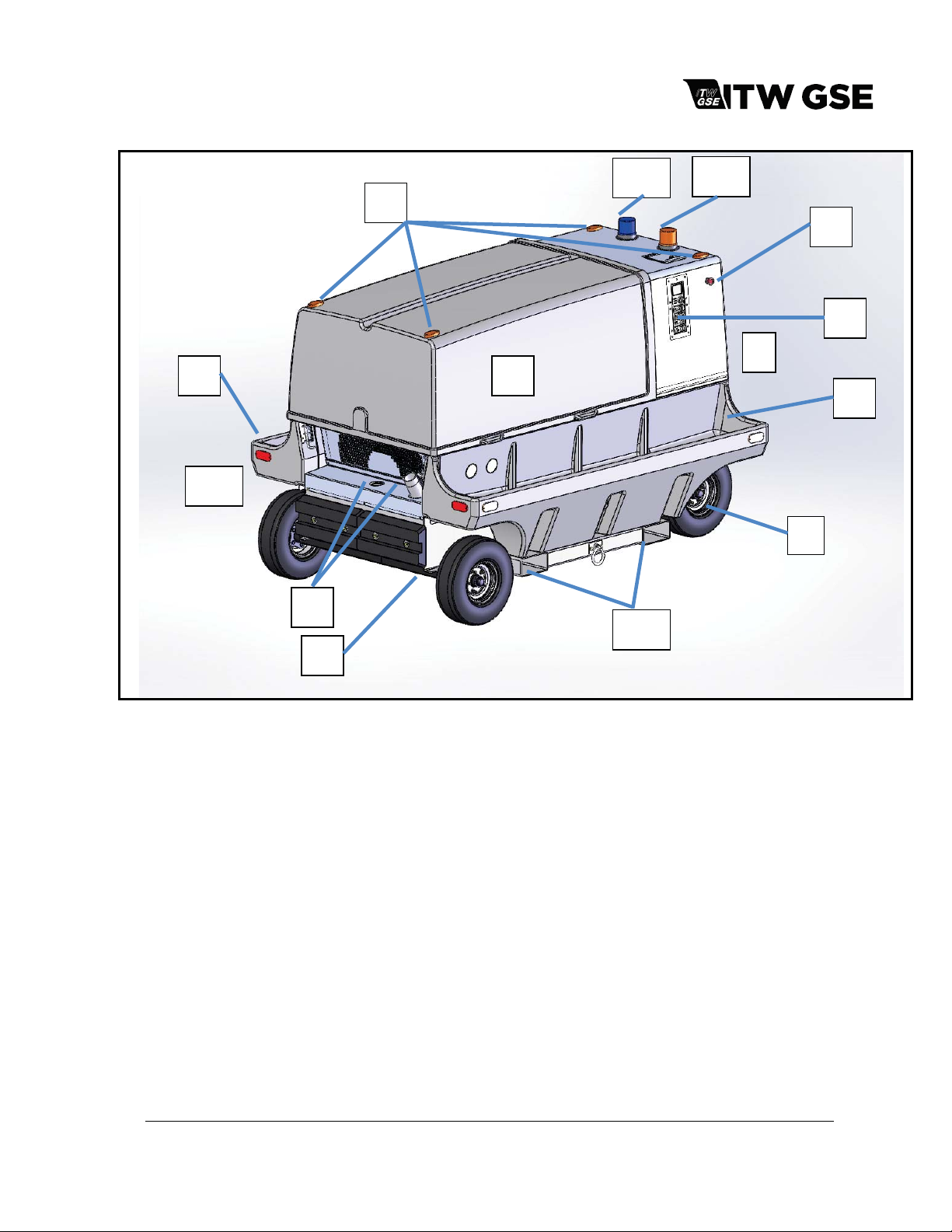
3) Component Locations
For purpose of orientation when designating RIGHT and LEFT throughout this manual, the radiator is
considered to be at the FRONT of the unit and the generator is at the REAR. RIGHT and LEFT are
determined by standing at the REAR facing the machine. As an example, the control panel is mounted
on the RIGHT FRONT side of the unit.
March 15, 2015 Chapter 1-1
Page 2
OM-2245 / Operation and Maintenance Manual
ITW GSE 4400 / 400 Hz. Generator Set
3
10
1
5
8
7
12
11
13
6
2
9
3
4
1. Fuel Filler Neck / Manual Gauge
2. Operator Control Panel
3. Composite Output Cable Trays
4. Fifth Wheel Assembly
5. Rear Axle Assembly
6. Emergency Stop Swit ch
7. Sliding/Removable Canopy
Figure 1-1-1: General Assembly of Generator Set
March 15, 2015 Chapter 1-1
8. Clearance Lights (Option)
9. Radiator End
10. Generator End
11. Forklift Pockets
12. Low Fuel Beacon (Option)
13. Operating Beacon (Option)
Page 3
OM-2245 / Operation and Maintenance Manual
ITW GSE 4400 / 400 Hz. Generator Set
9
7
6
2
10
1
5
8
4
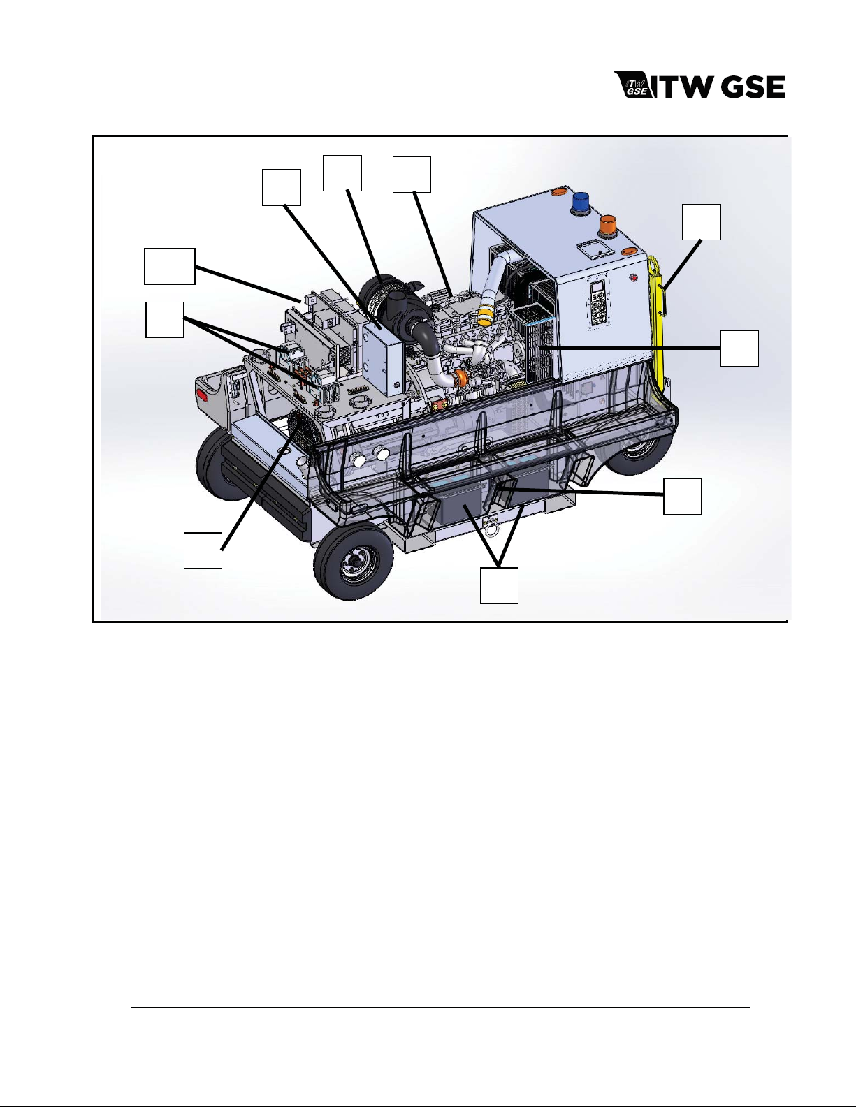
1. Cummins QSB4.5 Engine
2. Control Module Assembly
3. Batteries (inside tray pockets)
4. Battery Disconnect
5. Tow bar Assembly
Figure 1-1-2: Main Components of Generator Set (Right Side)
3
6. Generator
7. 28.5 VDC ARU (Option)
8. Engine Alternator
9. Output Contactors
10. Air Filter Assembly
March 15, 2015 Chapter 1-1
Page 4
OM-2245 / Operation and Maintenance Manual
ITW GSE 4400 / 400 Hz. Generator Set
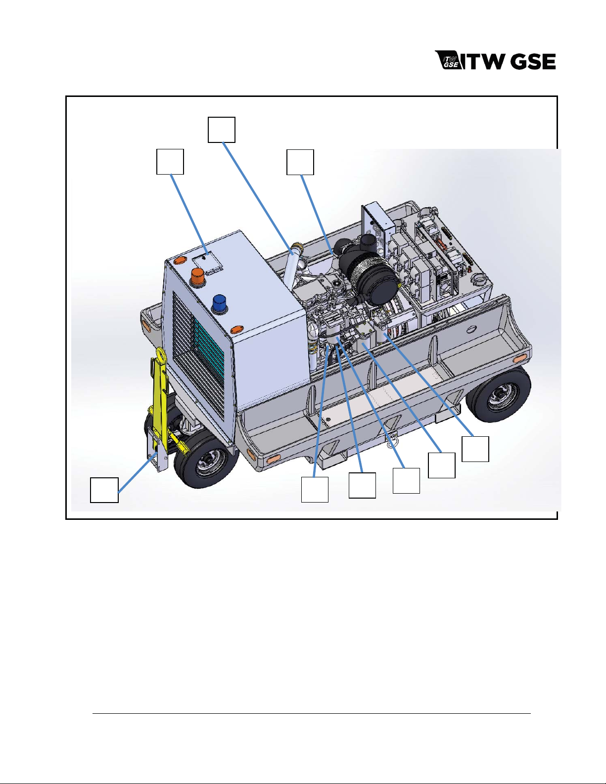
7
1
8
3
9
1. Coolant fill access cover
2. Lubricity Additive Fuel Pre-Filter
3. Engine Oil Filter
4. Fuel Filter
5. Engine Control Module (ECM)
Figure 1-1-3: Main Components of Generator Set (Left Side)
March 15, 2015 Chapter 1-1
6
6. Engine Oil Fill Tube
7. Charge-Air-Cooler Piping
8. Engine Air Intake Piping
9. Tow Bar/Brake Release Lever
5
4
2
Page 5
OM-2245 / Operation and Maintenance Manual
ITW GSE 4400 / 400 Hz. Generator Set
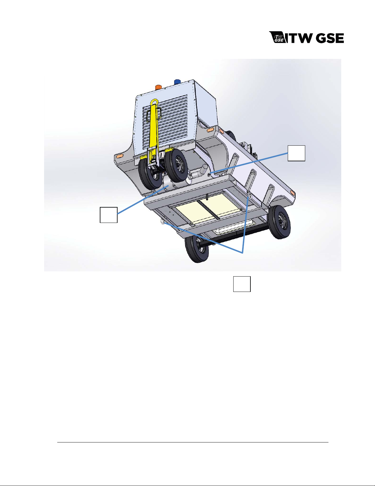
1
1. Oil Drain Tube
2. Tie Down Rings
3. Muffler Assembly
3
2
Figure 1-1-4: Main Components of Generator Set (Bottom)
March 15, 2015 Chapter 1-1
Page 6

OM-2245 / Operation and Maintenance Manual
ITW GSE 4400 / 400 Hz. Generator Set
4) Specifications
a) Physical Specifications
Length 103 in. (2615 mm) w/ towbar up
Width 66.7 in. (1694.3 mm)
Height 65.9 in. (1674 mm)
Weight (dry) 4000 lb. (1814 kg.)
Weight with 28.5 VDC T-R 4300 lb. (1950 kg.)
b) AC Generator Specifications
Output power rating 90 kVA (72 kW)
Output voltage 115 / 200 VAC
Rated load capacity 260 Amps
Frequency 400 Hz.
Power factor 0.8
Duty Cycle 100%
Operating speed 2000 RPM
Overload capacity 125% rated load 325 Amps
Output cable size 2/0
c) AC G ener ato r Prot ect iv e System Spe cifications
Condition Trip Point Time Delay
Over voltage 130 volts 250 milliseconds
140 volts 15 millisec o nds
Under voltage any voltage below 104 volts 500 milliseconds
Over frequency 380 Hz to 420 Hz 1 second
above 480 Hz immediate
Under frequency 380 Hz. or less 5 seconds
Output overload 80% load at PF > 0.8 to 1.0 Continuous
100% load at PF > 0.7 to 0.8 Continuous
100% load at PF > 0.8 to 1.0 5 minutes
100% to 120% load (PF 0.7 to 0.8) 10 seconds
120% to 150% load (PF 0.7 to 0.8) 2 seconds
March 15, 2015 Chapter 1-1
Page 7

OM-2245 / Operation and Maintenance Manual
ITW GSE 4400 / 400 Hz. Generator Set
d) DC Output Specifications (with optional TR unit)
Output Power Rating 17.1 kW
Output Voltage 28.5 VDC
Load Capacity (Continuous) 600 A
Current Limiting Capabilit y 400 to 2000 A in 300 A steps
Peak/Starting Load Capacity 2000 A for 5 seconds
Output cable size
e) DC Protective System Specifications
Condition Trip Point Time Delay
Over Voltage
Output Overload
f) Engine Specifications
Manufacturer and Model Cummins Engine Company / QSB4.5
Type 4 cylinder, 4 cycle diesel, electronic controlled
Bore and Stroke 4.21 in. x 4.88 in. (107 mm x 124 mm)
Displacement 275 in3(4.5 L)
Horsepower 171 hp (132 kW)
Idle speed (factory set option)
(Not authorized for EU units)
Normal governed speed 2000 rpm
Firing Order 1-3-4-2
Electrical system 24 VDC
Lubricating oil capacity (w/ filter) 11.6 quarts (11 liters)
Coolant capacity system 20 quarts (18.9 liters)
4/0 for continuous loads up to 400A
2x 4/0 for continuous loads up to 600A
32 - 40 VDC
Over 40 VDC
2000 A 5 seconds
1800 A 10 seconds
1200 A 30 seconds
800 A 30 seconds
1000 ± 50 rpm
4 seconds
150 ms
g) Normal Operating Characteristi cs
Engine oil pressure (warm and at rated speed 2000 RPM) 45 to 90 PSI (445 to 621 kPa).
Engine coolant temperature (normal operation) 160 to 200º F (71 to 93º C).
March 15, 2015 Chapter 1-1
Page 8

OM-2245 / Operation and Maintenance Manual
ITW GSE 4400 / 400 Hz. Generator Set
5) Special Features
The generator set has special features that are described more fully under the assemblies in which they
appear.
a) Protective Monitoring
The protective monitoring system receives signals from the fault sensing components in the generator
output circuit and functions to cause the load to be disconnected from the generator if an abnormal
condition of voltage, frequency, or load develops. The nature of that abnormal condition is then
presented on the graphical display.
b) Voltage Regulator
A microprocessor-type, adjustable voltage regulator provides automatic voltage regulation at the
aircraft. The regulated output is also adjustable for a variety of output cable sizes and lengths.
c) Engine Electronic Control Module
The engine is equipped with an electronic control module that monitors, records, and controls engine
performance.
d) Battery System Disconnect Switch
The generator set is equipped with a battery disconnect switch outside the unit on the RIGHT side.
The disconnect switch should be placed in the OFF position during long periods of shutdown.
6) Canopy
A composite enclosure, identified as a canopy, provides protection for the engine, generator and electrical
controls. The canopy is also designed to reduce the operational noise level in the immediate area of the
machine.
7) Engine and Generator
The engine and generator comprise the principal components of the generator set. They are mounted on
a galvanized, welded steel frame chassis. The following figures show the locations of all major
components and sub-assemblies.
a) Diesel Engine
The diesel engine is a fuel injection, 4-cylinder, electronically controlled engine rated at 171
horsepower.
b) Engine Manufacturer’s Components
As received from the engine manufacturer, the engine includes some of the following components,
which are mor e full y descri bed in t he eng ine m anuf ac turer’s manual.
March 15, 2015 Chapter 1-1
Page 9

OM-2245 / Operation and Maintenance Manual
ITW GSE 4400 / 400 Hz. Generator Set
(1) Electrical System
The 24 VDC electrical generating and starting system includes an alternator and starter with
solenoid switch.
.
(2) Lubricity Additive Fuel Filter
The fuel filter is a spin-on disposable type located on the inside of the canopy, near the engine’s
fuel pump. The fuel filter’s primary function, other than removing contaminants from the fuel, is to
automatically add a lubricity additive to the fuel. Although, the engine manufacturer does not
recommend low lubricity fuels, this additive can extend the life of the fuel pump.
CAUTION
(3) Oil Filter
The engine oil filter is a spin-on, full-flow type, located on the left side of the engine near the front.
(4) Pre-programmed Electronic Control Module (ECM)
The ECM is a pre-programmed engine control module, mounted directly to the engine block.
c) Factory Installed Components and Protective Systems
This generator set is assembled with the following components and protective systems:
(1) Shutdown/Reset Systems
x Emergency Shutdown
The use of low lubricity fuels can shorten life and/or damage the engine’s fuel pump.
Only diesel fuel is recommended by the engine manufacturer. Refer to engine
manufacturer’s manual for approved fuels.
The emergency shutdown switch is to provide instant manual shut off of the generator set
by disconnecting power to the ECM through the control box. It is located on the FRONT
RIGHT of the generator set next to the control box.
To operate the EMERGENCY SHUTDOWN
x Push button in until engine stops or until button travel stops
x Pull the button back out to reset
CAUTION
Do not use the “EMERGENCY STOP BUTTON” button as a normal shutdown device.
Damage to the engine turbo charger may result without proper cooling time. Use the
Engine ON/OFF push-button for all normal engine shutdowns.
x Low fuel warning system
The low fuel warning system monitors the fuel level in the fuel tank. When the fuel tank
level reaches approximately 10%, a warning is generated signifying that it is time to put
fuel in the tank. Once the engine is not running, a low fuel fault is generated and the
engine is not allowed to start.
March 15, 2015 Chapter 1-1
Page 10

OM-2245 / Operation and Maintenance Manual
ITW GSE 4400 / 400 Hz. Generator Set
(2) Radiator and Charge-A ir -C ooler (CAC)
The radiator and charge-air-cooler is a two-piece type designed for long periods of operation
without servicing.
(3) Engine-cooling fan
The engine fan is designed to blow air outward through the radiator, rather than pulling the air
inward as a conventional fan does.
(4) Master [Battery] Disconnect Switch
The master disconnect switch is designed to isolate the batteries from the entire electrical system
to eliminate the possibility of battery current draw by the engine ECM or any other components
during long periods of no operation. The switch can also be used to lock-out the starting circuit of
the equipment for maintenance safety purposes.
(5) Air cleaner
The diesel engine air cleaner is so constructed that air enters through its cylindrical body, and
then is filtered before being passed into the engine turbo-charger assembly. An air cleaner
service indicator device is mounted on the air cleaner assembly to monitor the airflow into the air
cleaner. As the air cleaner becomes filled with dust, dirt, and carbon, the intake system airflow
becomes increasingly restricted. This restriction causes a diaphragm inside the indicator to move
toward an electrical contact. When the maximum allowable restriction level is reached, the circuit
closes and the air cleaner indicator fault appears on the control panel fault display to warn the
operator that the air cleaner must be changed. The electrical indicator automatically resets when
the restriction level drops sufficiently. Note: This function should not be used as a replacement
indicator. Follow recommended replacement schedule as specified in this manual.
d) Warnings/Faults
The control system reacts appropriately to different detected issues. These types can be generalized
between warnings and faults. Warnings are given when the system is able to function but requires
servicing/user interaction. Faults are generated when the unit cannot or should not supply regulated
power to the aircraft.
All faults prevent the engine from starting. However, they react differently to an operating unit. Faults
can be categorized into three subcategories as defined by the fault number.
x Fault numbers less than 6000
o Minor faults: Disconnect power to the aircraft but do not affect engine and generator
functions.
x Fault numbers between 6000 and 8000
o Mid-level faults: Disconnect power to the aircraft, turn off the generator and shut down
the engine after the required 5 minute cool down.
x Fault numbers greater than 8000
o Major faults: Result in immediate shutdown of all system components including the
engine. Service is required on the unit before it is returned to operation.
Engine generated warnings and faults are also monitored and their respective Cummins fault
numbers are shown on the display.
March 15, 2015 Chapter 1-1
Page 11
OM-2245 / Operation and Maintenance Manual
ITW GSE 4400 / 400 Hz. Generator Set
e) Generator
The 400 Hz generator is a brushless, dual bearing, revolving field, three-phase, alternating current
type unit. The front end of the rotor shaft extends forward beyond the front bearing and is coupled to
the engine flywheel by a flexible coupling assembly. The rear end of the rotor shaft extends rearward
beyond the rear bearing and into the exciter stator housing. The exciter rotor is mounted on this shaft
extension with a key and is secured by a washer and 1/2-13 thread cap screw.
The rectifier has six diodes mounted on the exciter rotor and converts exciter AC output to DC for
excitation of the generator revolving fields. The exciter outputs DC to the generator fields, and
consequently the generator output, is controlled by the voltage regulator PC board (REG). A
centrifugal, radial-blade fan draws cooling air over all internal windings. Air enters at the exciter end
and is discharged at the drive end. The complete generator assembly is bolted to the engine’s
flywheel and hous ing.
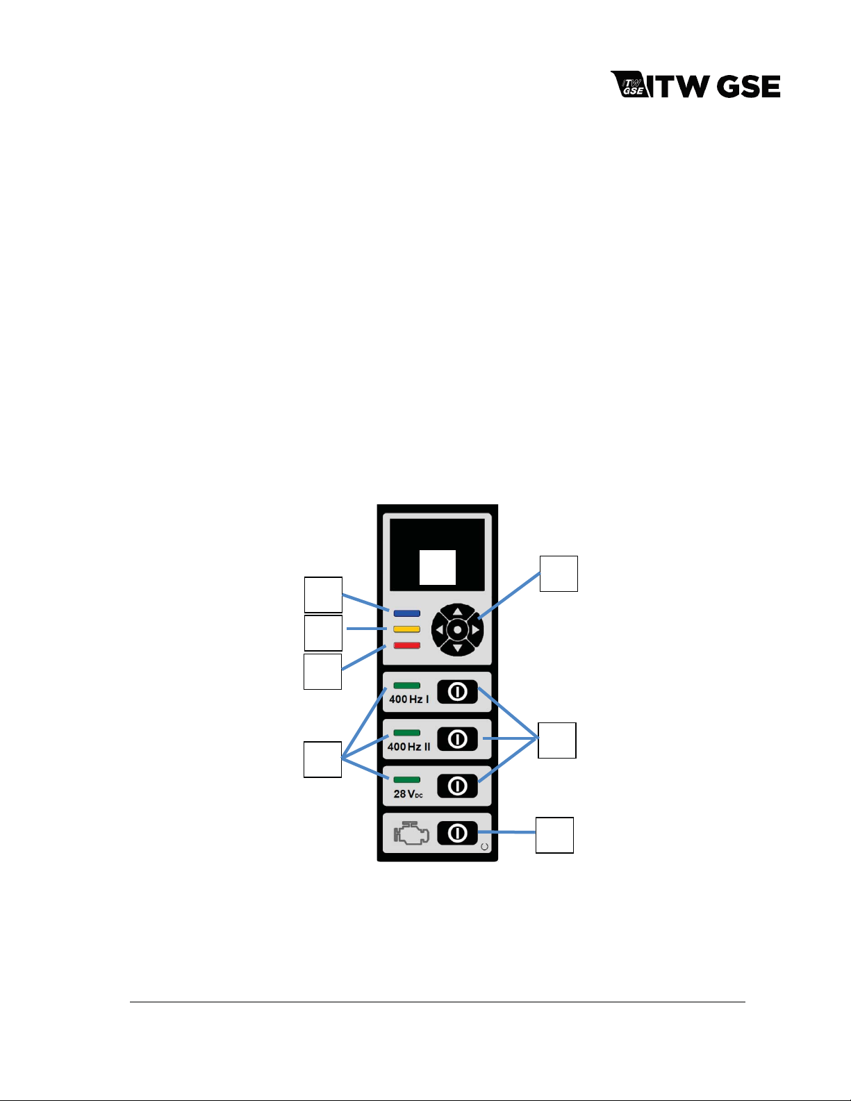
8) Operator Controls
The control box is a protected enclosure on the right front panel of the GPU that has a modern graphical
display and easy to understand controls. The display allows the user to easily have access to all critical
operational information as well as providing textual descriptions of all warnings and failures.
a) Operator Controls
3
4
5
6
1
2
7
8
1. LED Graphical Display
2. Navigation Keypad
3. Power ON "Blue" LED
4. Warning "Amber" LED
March 15, 2015 Chapter 1-1
5. Alert/Failure "Red" LED
6. Output ON "Green" LEDs
7. Output ON/OFF (Reset)
8. Power ON & Engine Start/Stop (Reset)
Page 12

OM-2245 / Operation and Maintenance Manual
ITW GSE 4400 / 400 Hz. Generator Set
Figure 1-1-5 Control Panel
1: The color LED Graphical Display and easy to use menu system places all required operational
information at the fingertips of the operator/maintenance personnel. Its color presentation accents
critical data and simplifies the troubleshooting process by giving textual descriptions of any potential
issues.
2: The navigation keypad is used to navigate through the simple menu systems.
3: The blue LED indicates that power is on. (It is off in sleep mode)
4: The Amber LED indicates a warning. The details of that warning are available on the display. Up to
five warnings can be displayed at one time.
5: The Red LED indicates a fault. The details of this fault are also visible on the graphics display.
Only one fault can be displayed at one time.
6: The green LED’s indicate that the respective output is on.
7: The ON/OFF buttons are used to turn on and off their respective outputs. If a specific output has a
fault, the corresponding ON/OFF button will also reset that fault.
8: The power ON & Engine Start/Stop button will wake the unit from low-power sleep mode. Pressing
it again will begin the start-up sequence for the diesel engine. Pressing it again will shut down the
engine. If the engine is already running, it will begin the manufacturer required 5 minute cool down. If
the unit has a fault, this button will reset the fault.
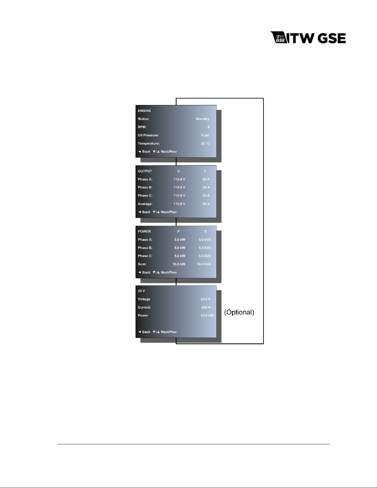
Default Screen:
There are two default displays depending on whether the engine is running or not. When the engine
is not running, the following screen is visible:
During the startup process, the screen will be modified to show the current status until the engine is
running and the unit is ready to output power.
Note: If the engine is configured to go to idle until an output is activated, it will still say it is ready for
use. However, the engine will have to ramp up to 2000 RPM and the voltage stabilized before the
output contactor will close.
When output power is ready, the screen will appear as follows showing all available outputs:
March 15, 2015 Chapter 1-1
Page 13
OM-2245 / Operation and Maintenance Manual
ITW GSE 4400 / 400 Hz. Generator Set
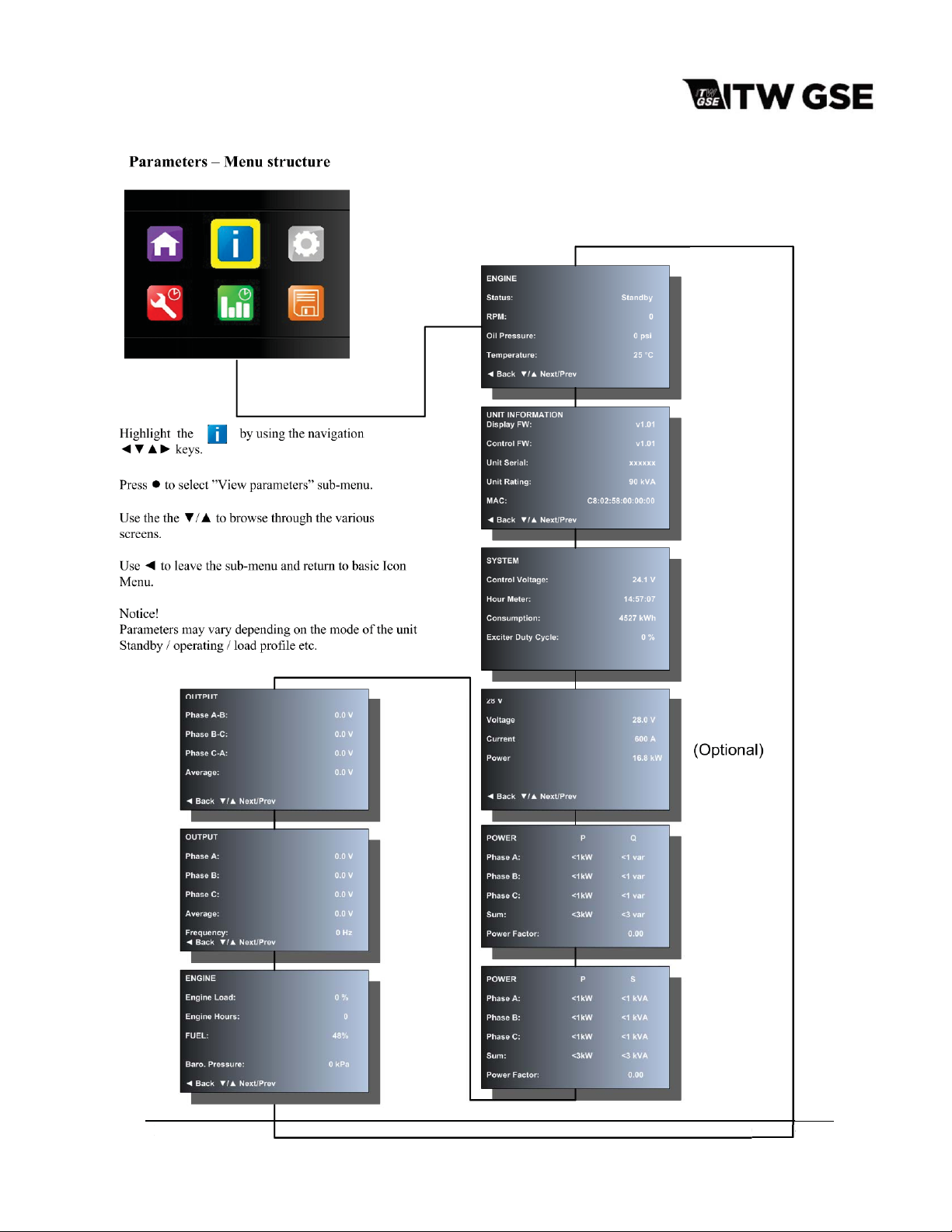
Both default screens enable the user to quickly have access to other pertinent information by
pressing źRUŸ to cycle through the display screens below:
The 28V data page will only be displayed if that option is available.
Pressing
Unit information is displayed using the information icon. To access the information icon, press the To enter
the Icon Menu, press the Ɣ from the default menu and hold it down for approximately 5 seconds.
To Select a submenu, simply use the navigation keys ŻźŸŹ to highlight the icon and then press the Ɣ to
enter the sub-menu.
To leave the Icon Menu highlight the ”Home” icon and press Ɣ
March 15, 2015 Chapter 1-1
Ż will return to the default menu screen.
Page 14
OM-2245 / Operation and Maintenance Manual
5
C
ITW GSE 4400 / 400 Hz. Generator Set
March 15, 2015 Chapter 1-1
March 15,201
hapte
Page 15

OM-2245 / Operation and Maintenance Manual
ITW GSE 4400 / 400 Hz. Generator Set
9.0 Power Module Assembly
The power module assembly, mounted to the back of the ARU bracket, is located at the rear of the
machine over the generator. The panel assembly provides a means of connecting and disconnecting the
generator output to and from the aircraft.
a) Load contactor (K1 and K2)
Each load contactor contains a magnetic operating coil and four sets of contacts. The three larger
contacts conduct three-phase AC generator output. A small contact set is connected to the Digital
Control PC Board (CTL) to activate the protective monitor circuit. Three-phase, 400-Hz generator
output power is distributed to the load contactor by 2/0 cables that pass through current transformers.
b) Current transformers (CT1-CT3)
A set of current transformers are used to monitor and control the line-drop compensation, ammeter,
and overload circuit.
(1) Line-Drop Compensation
The current transformers detect the magnitude and power factor of current flowing from generator
to load. They feed a signal to the voltage regulator that interprets the signal and alters the exciter
field current as required to maintain a constant predetermined voltage at the load. These values
are accessible on the color display.
(2) Ammeter
The current transformers convert a current signal to a voltage signal, which is sent to the interface
board and read by the processor boards. This signal is digitized and sent to the display board
where it is able to be read by the user on the color display in phase to phase or phase to N
format.
(3) Overload
The digitized signal is also processed to determine if the generator output is within the defined
specifications. If the current is within the following values, then the output contactor(s) are opened
at the prescribed time.
Continuous 100% rated load at PF 0.7 - 0.8
Continuous 80% rated load at PF 0.8 - 1.0
5 minutes 100% rated load at PF 0.8 - 1.0
10 seconds 120% rated load at PF 0.7 - 0.8
2 seconds 150% rated load at PF 0.7 - 0.8
March 15, 2015 Chapter 1-1
Page 16
OM-2245 / Operation and Maintenance Manual
ITW GSE 4400 / 400 Hz. Generator Set
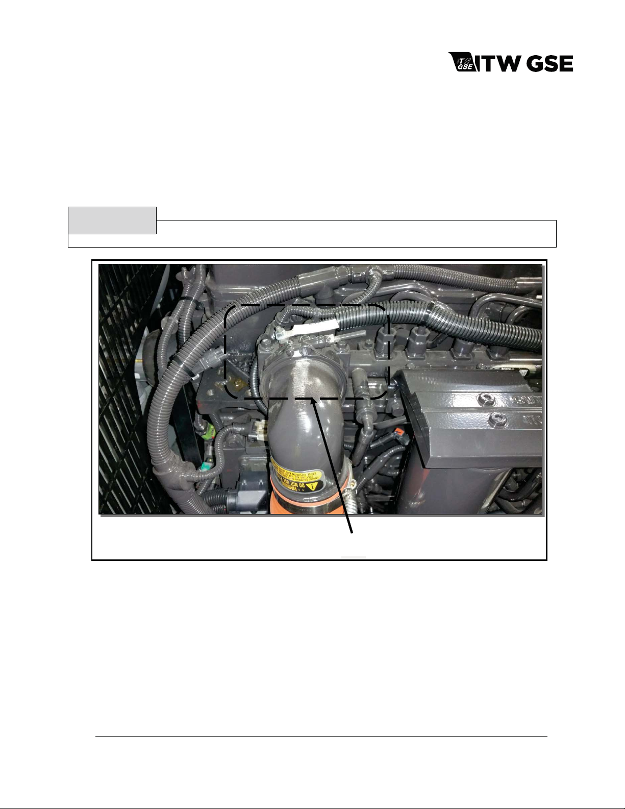
10) Cold Weather Starting System (BH1)
The intake air heater, located on the intake manifold, is used for starting the engine at very cold
temperatures and reduces the white smoke associated with a cold start. The intake air heater (or grid
heater) is energized or de-energized from a power relay controlled by the ECM. The amount of time the
air intake heaters stay on, in the preheat phase, is a function of the intake manifold temperature at start
up. (The pre-heat time increases with colder intake manifold temperatures). The maximum duration of
the pre-heat phase is around 30 seconds.
CAUTION
Never use an ether start system in conjunction with the air intake heater.
Air Intake Heater
Figure 1-1-6: Air Intake Heater
March 15, 2015 Chapter 1-1
Page 17
OM-2245 / Operation and Maintenance Manual
ITW GSE 4400 / 400 Hz. Generator Set
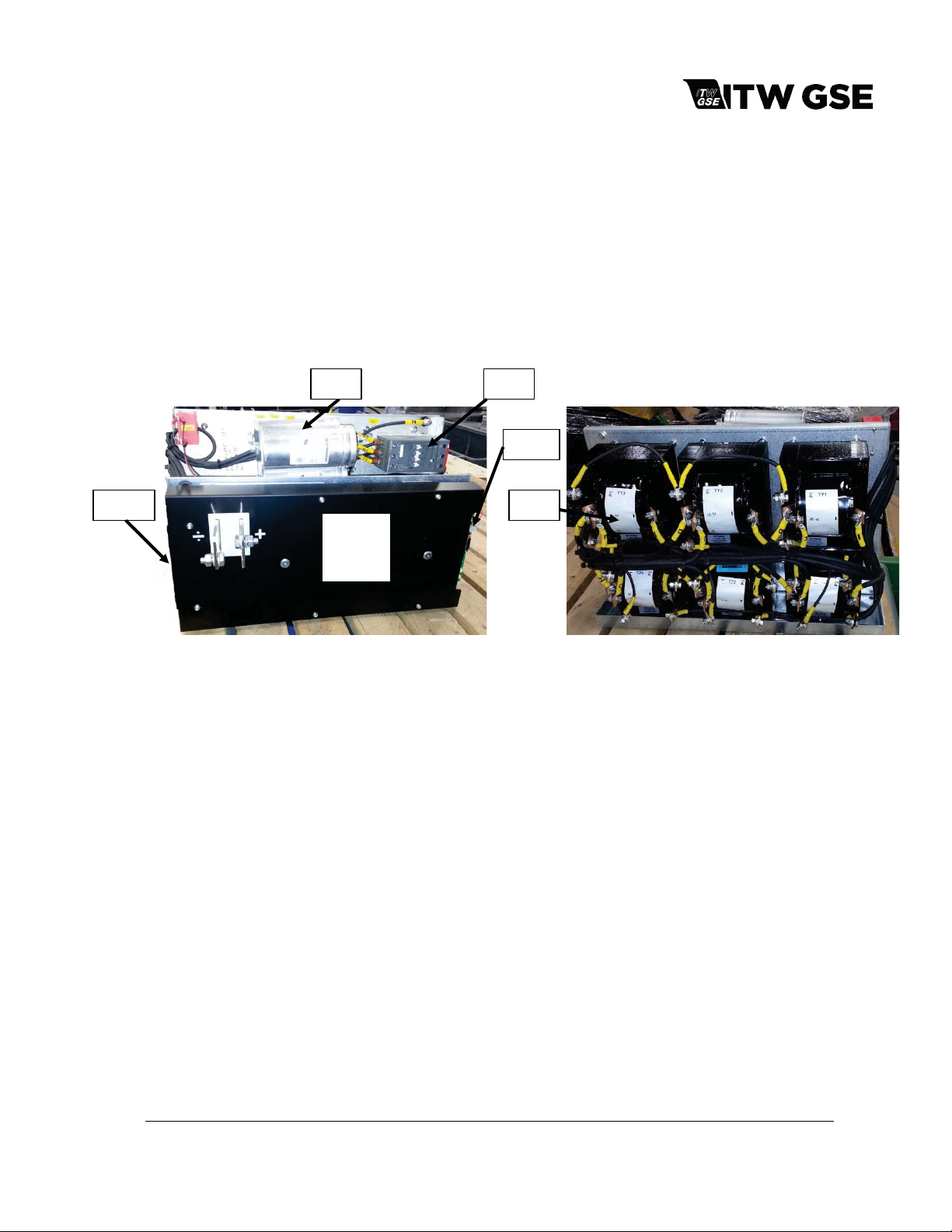
11)Active Rectifier Unit (ARU)
The ARU provides a regulated output voltage of 28.5 VDC. Input power is provided to the DC components
from the 115/200 volt, 400 Hz generator set, through an input contactor. The output contactor provides DC
power to the load. Both 400 Hz & 28 VDC outputs can be used simultaneously. The 28 VDC power is
provided by an Active Rectifier Unit which is supplied from the 400 Hz output. The 28 VDC output voltage is
controlled regardless of any variations in the 400 Hz input voltage. The total continuous amount of power from
the unit is calculated as the sum of the 400 Hz and 28 VDC outputs and cannot exceed units 400 Hz power
rating.
M20
Figure 1-1-7 ARU Front view Figure 1-1-8 ARU Rear View
Input Contactor (Q3):
The 400 Hz input power to the ARU is supplied and controlled via Q3.
Supply Module (G20):
The generation of the 24 VDC / 10 A (Adjusted from factory = 25 Volt) regulated control voltage is done by the
Supply Module G20. This module has a wide input range (340-575 VAC). It is supplied via the capacitor
C20
A20,
PM20
R20
Q3
G20
T20
module and pre-fused from the 3-phase circuit breaker Q4 (shared with G1) and located in 400 Hz part.
Refer to section 3.0 for picture.
ARU Transformers (T20):
The ARU transformer s receive the 3 phased 400 Hz vo ltage 3 x 200 Vac and steps do wn the voltage to an
appropriate level to obtain 28 VDC at the output.
ARU Rectifier (PM20):
By controlling six thyristors the output voltage is kept at 28 VDC, regardless of the input voltage level and the
load.
March 15, 2015 Chapter 1-1
Page 18
 Loading...