

ITW Gema PG 1-R1 Operating Instructions And Spare Parts List
17PG 1-R1
Issued 05/01
Operating Instructions and Spare Parts List
PG 1-R1 Robot Powder Gun
E

18 PG 1-R1
Issued 05/01

19PG 1-R1
Issued 05/01
Table of Content
PG 1-R1 Robot Powder Gun . . . . . . . . . . . . . . . . . . . . . . . . . . . . . . . . . . . . . . . . . . . . . 1
Technical data of the PG 1-R1 Robot Powder Gun . . . . . . . . . . . . . . . . . . . . . . . . . . . . 1
Functional description . . . . . . . . . . . . . . . . . . . . . . . . . . . . . . . . . . . . . . . . . . . . . . . . . . 2
1. High-Voltage generation . . . . . . . . . . . . . . . . . . . . . . . . . . . . . . . . . . . . . . . 2
2. Powder flow and supplementary air . . . . . . . . . . . . . . . . . . . . . . . . . . . . . . 2
3. Flat jet nozzle with vented centre electrode . . . . . . . . . . . . . . . . . . . . . . . . 3
Preparatory steps for initial start-up . . . . . . . . . . . . . . . . . . . . . . . . . . . . . . . . . . . . . . . 4
a) Connecting the PG 1-R1 Powder gun . . . . . . . . . . . . . . . . . . . . . . . . 4
b) Functional check . . . . . . . . . . . . . . . . . . . . . . . . . . . . . . . . . . . . . . . . 5
Start-up . . . . . . . . . . . . . . . . . . . . . . . . . . . . . . . . . . . . . . . . . . . . . . . . . . . . . . . . . . . . . 6
a) Adjusting the powder output and powder cloud . . . . . . . . . . . . . . . . 6
b) Powder coating - Start-up . . . . . . . . . . . . . . . . . . . . . . . . . . . . . . . . . 6
c) Shut-down . . . . . . . . . . . . . . . . . . . . . . . . . . . . . . . . . . . . . . . . . . . . . 6
d) Rinsing the powder hose . . . . . . . . . . . . . . . . . . . . . . . . . . . . . . . . . . 6
Maintenance schedule . . . . . . . . . . . . . . . . . . . . . . . . . . . . . . . . . . . . . . . . . . . . . . . . . 7
a) Daily maintenance . . . . . . . . . . . . . . . . . . . . . . . . . . . . . . . . . . . . . . . 7
b) Weekly maintenance . . . . . . . . . . . . . . . . . . . . . . . . . . . . . . . . . . . . . 7
Cleaning and repairs . . . . . . . . . . . . . . . . . . . . . . . . . . . . . . . . . . . . . . . . . . . . . . . . . . . 7
PG 1-R1 Powder Gun . . . . . . . . . . . . . . . . . . . . . . . . . . . . . . . . . . . . . . . . . . . 7
a) Cleaning . . . . . . . . . . . . . . . . . . . . . . . . . . . . . . . . . . . . . . . . . . . . . . . 7
b) Gun dismantling: . . . . . . . . . . . . . . . . . . . . . . . . . . . . . . . . . . . . . . . . 8
c) Gun assembly . . . . . . . . . . . . . . . . . . . . . . . . . . . . . . . . . . . . . . . . . . 9
e) Cleaning the Spray nozzles . . . . . . . . . . . . . . . . . . . . . . . . . . . . . . . 10
Trouble shooting guide . . . . . . . . . . . . . . . . . . . . . . . . . . . . . . . . . . . . . . . . . . . . . . . . 11
Spare Parts List . . . . . . . . . . . . . . . . . . . . . . . . . . . . . . . . . . . . . . . . . . . . . . . . . . . . . . 13
Ordering Spare Parts . . . . . . . . . . . . . . . . . . . . . . . . . . . . . . . . . . . . . . . . . . . 13
PG 1-R1 Robot Powder Gun . . . . . . . . . . . . . . . . . . . . . . . . . . . . . . . . . . . . . . . . . . . . 14

20 PG 1-R1
Issued 05/01
1PG 1-R1
Issued 05/01
PG 1-R1 Robot Powder Gun
The PG 1-R1 Robot Powder Gun with integrated High-voltage generation is especially suited
for operation on a freely programmable Robot (up to 7 axes) for coating complex contours
and difficult to reach workpiece positions. The gun has very good penetration capability, and
a high, constant Transfer efficiency. The gun is easily dismantled, making it maintenance and
repair-friendly.
For fitting the gun on the Robot, the customer must supply the necessary Adapter for the
corresponding Robot type, by means of a pin for the exact positioning of the gun and also a
carrier for the gun cable and hoses.
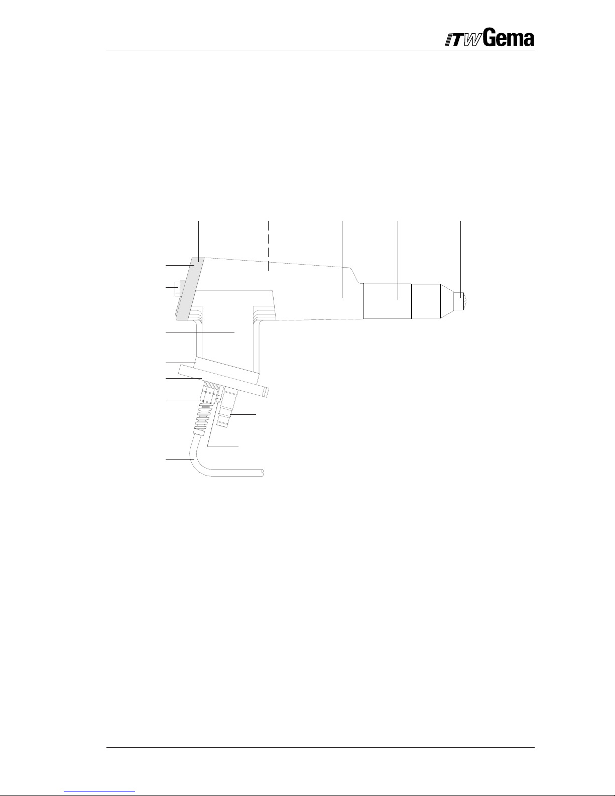
8
3
4
7
9
6
1
2
16
10
11
12
15
8 Support
9 Flange plate
10 Locking screw
11 Gun cable connection
12 Gun cable
15 Powder hose connection
16 Rinsing air connection
1 Atomizing system
2 Threaded sleeve
3 Shaft
4 HV cascade
5 End plate
6 LED window
7 Plastic bolt
Technical data of the PG 1-R1 Robot Powder Gun
Rated input voltage: 10 V eff.
Frequency: 17 kHz
Rated output voltage: 98 kV
Polarity: negative
Maximum output current: 140 µA
HV indication: LED
Polarity: Negative
Approval: EN 50050
PTB test No. Ex-91.C.9102
Date PTB tested Oct. 1991
Figure 1
5
2 PG 1-R1
Issued 05/01
Functional description
1. High-Voltage generation
The voltage generation module (Control module) supplies high-frequency low-voltage.
This voltage is conducted by the gun cable (12) and the gun connector (11) in the Support to
the high-voltage cascade (4).
This low voltage is stepped up (c) in the cascade (4). This primary high-voltage is subsequently rectified and multiplied in several stages in the cascade (d) until the required highvoltage is attained.
The high-voltage is then fed from the spray nozzle to the electrode (e). See Figure 3.
When the high-voltage is adjusted on the control module, the intensity of the LED (6) also
changes. The user has the assurance that high-voltage is present and has control over this
function.
Figure 2
2. Powder flow and supplementary air
The supplementary air, serving as rinsing air, is connected to the gun, shown in Figure 4,
when air-cleaned nozzles are used.
The function of the nozzles are described in the applicable sections (see page 3).
4
11
12
c
d
6
e
 Loading...