

ITW Gema EasyTronic Operating Instructions And Spare Parts List
23
EasyTronic
Issued 07/02
Operating Instructions and Spare Parts List
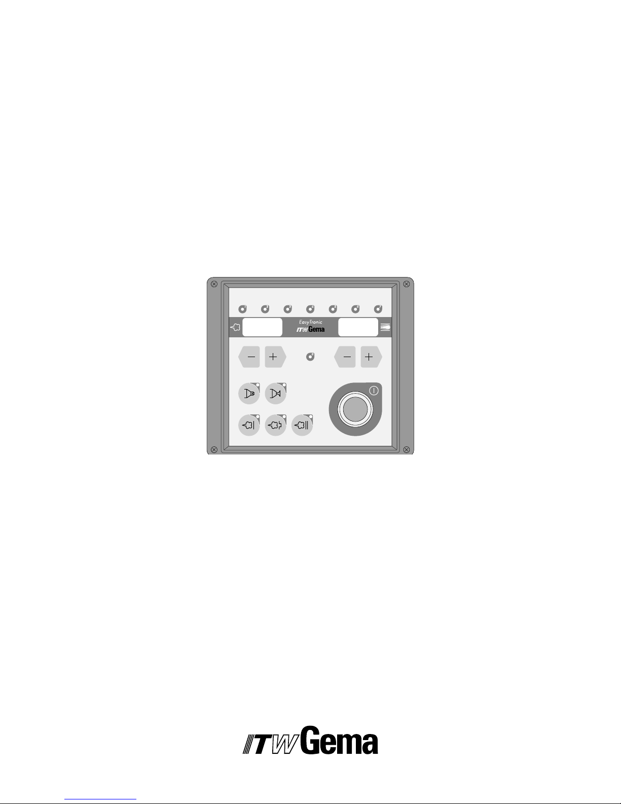
EasyTronic
Control Unit
E
24
EasyTronic
Issued 07/02
Mains connectionAux
Gun
1.1 IN
5 ... 10 bar
73...145 PSI
1.4 2.2 2.3
2.1
1.3
1.2 1.5
Input voltage:
Input power:
Degree of protection:
Output:
Corresponding guns:
85 – 264 V
47 – 440 Hz
65 VA
IP 54
10 V 1,2 A
EasySelect
POWDER GUN CONTROL
TYPE EASYTRONIC
CONNECTIONS ON THE REAR OF THE EASYTRONIC CONTROL UNIT
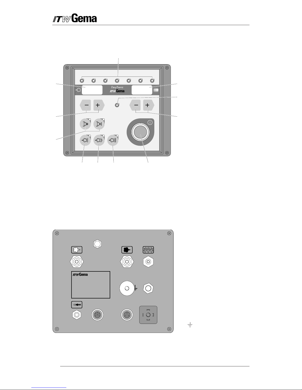
1 Diagnostic LEDs
2 Powder output display
3 Key for setting the
powder output
4 Electrode rinsing air key
5 Application key for flat
parts
6 Application key for
complicated parts
7 Application key for
overspraying
8 On / Off Push button
9 Key for setting the total
air volume
10 Diagnostic LED for High-
voltage
11 Total air volume display
EASYTRONIC CONTROL UNIT - FRONT VIEW
1.1 IN Compressed air input
1.2 Conveying air connection
1.3 Supplementary air connection
1.4 Rinsing air connection
1.5 Fluidizing air connection
2.1 Mains input (85-264 V)
2.2 Gun connection for the
EasySelect Manual Powder
Gun.
PG 1 manual powder guns
cannot
be connected here!
2.3 Output for Vibrator (EASY 1-B
only) and Stirrer control unit
(EASY 1-S only)
Ground connection
11
1
0
9
4
3
2
1

25
EasyTronic
Issued 07/02
Table of Contents
Directions for use
Safety rules for electrostatic Powder coating
Technical Data - EasyTronic Control unit
EasyTronic Control Unit . . . . . . . . . . . . . . . . . . . . . . . . . . . . . . . . . . . . . . . . . . . . . . . . . . . . .1
Field of Application . . . . . . . . . . . . . . . . . . . . . . . . . . . . . . . . . . . . . . . . . . . . . . . . 1
Operating mode . . . . . . . . . . . . . . . . . . . . . . . . . . . . . . . . . . . . . . . . . . . . . . . . . . 1
Description of the EasyTronic Control unit . . . . . . . . . . . . . . . . . . . . . . . . . . . . . . . . . . . . . . 2
Installation of the Powder coating equipment . . . . . . . . . . . . . . . . . . . . . . . . . . . . . . . . . . . 3
Preparation for Start up . . . . . . . . . . . . . . . . . . . . . . . . . . . . . . . . . . . . . . . . . . . . . . . . . . . . . 4
a) Setting the Operating mode on the Electronic board . . . . . . . . . . . . . . . . . . . . . 4
b) Preparation of the Powder hopper / container . . . . . . . . . . . . . . . . . . . . . . . . . . 5
c) Switching on the Booth . . . . . . . . . . . . . . . . . . . . . . . . . . . . . . . . . . . . . . . . . . . 5
d) Function check . . . . . . . . . . . . . . . . . . . . . . . . . . . . . . . . . . . . . . . . . . . . . . . . . 5
Daily Start up . . . . . . . . . . . . . . . . . . . . . . . . . . . . . . . . . . . . . . . . . . . . . . . . . . . . . . . . . . . . . . 6
a) Setting the Powder output, and Powder cloud . . . . . . . . . . . . . . . . . . . . . . . . . 6
Set the Total air volume . . . . . . . . . . . . . . . . . . . . . . . . . . . . . . . . . . . . . . . 6
Select the Powder output volume . . . . . . . . . . . . . . . . . . . . . . . . . . . . . . . . 6
Select the electrode rinsing . . . . . . . . . . . . . . . . . . . . . . . . . . . . . . . . . . . . . 6
b) Powder coating . . . . . . . . . . . . . . . . . . . . . . . . . . . . . . . . . . . . . . . . . . . . . . . . . 7
c) Remote control through the Powder gun . . . . . . . . . . . . . . . . . . . . . . . . . . . . . 7
d) Switching off . . . . . . . . . . . . . . . . . . . . . . . . . . . . . . . . . . . . . . . . . . . . . . . . . . . 7
When the Powder coating equipment is not used for a number of days . . 7
Repairs to Electrical parts of the Control unit . . . . . . . . . . . . . . . . . . . . . . . . . . . . . . . . . . . . 8
a) Replacing fuse(s) . . . . . . . . . . . . . . . . . . . . . . . . . . . . . . . . . . . . . . . . . . . . . . . . 8
b) Replacing the CG 01 Printed Circuit Board . . . . . . . . . . . . . . . . . . . . . . . . . . . . 9
c) Replacing the Front plate . . . . . . . . . . . . . . . . . . . . . . . . . . . . . . . . . . . . . . . . . 10
Dismantle Main switch . . . . . . . . . . . . . . . . . . . . . . . . . . . . . . . . . . . . . . . 10
Repairs to Pneumatic parts in the Control unit . . . . . . . . . . . . . . . . . . . . . . . . . . . . . . . . . 11
a) Replacing a Pneumatic Part . . . . . . . . . . . . . . . . . . . . . . . . . . . . . . . . . . . . . . . 11
Removing the pneumatic tubes . . . . . . . . . . . . . . . . . . . . . . . . . . . . . . . . 11
Replacing the pneumatic tubes . . . . . . . . . . . . . . . . . . . . . . . . . . . . . . . . . 11
Troubleshooting Guide . . . . . . . . . . . . . . . . . . . . . . . . . . . . . . . . . . . . . . . . . . . . . . . . . . . . . 12
Pneumatic diagram . . . . . . . . . . . . . . . . . . . . . . . . . . . . . . . . . . . . . . . . . . . . . . . . . . . . . . . .14
Block Diagram . . . . . . . . . . . . . . . . . . . . . . . . . . . . . . . . . . . . . . . . . . . . . . . . . . . . . . . . . . . . 15
Display of the Operating Time . . . . . . . . . . . . . . . . . . . . . . . . . . . . . . . . . . . . . . . . . . . . . . . 16
Spare parts list . . . . . . . . . . . . . . . . . . . . . . . . . . . . . . . . . . . . . . . . . . . . . . . . . . . . . . . . . . . 17
Ordering Spare parts . . . . . . . . . . . . . . . . . . . . . . . . . . . . . . . . . . . . . . . . . . . . . . 17
EasyTronic Control Unit - Pneumatic Parts . . . . . . . . . . . . . . . . . . . . . . . . . . . . . 18
EasyTronic Control Unit - electrical Parts . . . . . . . . . . . . . . . . . . . . . . . . . . . . . . . 20
EasyTronic Control Unit - Accessory . . . . . . . . . . . . . . . . . . . . . . . . . . . . . . . . . . 21

26
EasyTronic
Issued 07/02

27
EasyTronic
Issued 07/02
DIRECTIONS FOR USE
Safety rules for electrostatic Powder coating
1. This equipment can be dangerous when not operated according
to the following standards:
EN 50 050 (or VDE 0745 Part 100),
EN 50 053 Part 2 (or VDE 0745 Part 102),
and specification sheet, ZH 1/443 Electrostatic Powder Coating.
2. All electrically conductive parts within 5 m of the coating area,
especially the workpieces, must be grounded.
3. The floor in the coating area must be electrically conductive
(normal concrete is generally conductive).
4. The operating personnel must wear electrically conductive footwear (i.e. leather soles).
5. The operating personnel should hold the powder gun in the bare
hand. If gloves are worn they must be electrically conductive.
6. Connect the grounding cable (green/yellow) supplied to the
grounding screw of the electrostatic manual powder coating
equipment. The grounding cable must have a good metal to metal
connection with the powder coating booth, the powder recovery
equipment and the chain conveyor or the hangers of the objects.
7. The electric cables and powder hose to the guns must be laid out
so that they are protected from possible mechanical damage.
8. The powder coating equipment must switch on only after the
powder booth is in operation. If the booth breaks down, then the
powder coating equipment must switch off.
9. The grounding of all conductive parts is to be checked at least
once a week.
10. When cleaning the powder gun and when replacing nozzles the
control unit must be switched off.
28
EasyTronic
Issued 07/02
TECHNICAL DATA - EASYTRONIC CONTROL UNIT
Mains connection:
Input voltage: 90 - 264 V
Frequency: 47 - 440 Hz
Nominal output voltage (to gun): max. 12 V
S
Nominal output current (to gun): max. 1 A
Type of protection: IP 54
Temperature range: 0 °C to +40 °C
(+32 °F to +104 °F)
Approval:
Pneumatic Data
Main compressed air input: B.S.P.1/4" (Female)
Max. Input pressure: 10 bar
Min. Input pressure: 6 bar
Max. water content of the compressed air: 1.3 g/m
3
Max. oil vapour content of the compressed air: 0.1 mg/kg
Dimensions:
Width: 248 mm
Depth: 250 mm
Height: 174 mm
Weight: 5.2 kg
The EasyTronic Control Unit can only be used with the EasySelect
manual gun.
IMPORTANT
1
EasyTronic
Issued 07/02
EASYTRONIC CONTROL UNIT
Field of Application
The electrostatic EasyTronic Control Unit is designed exclusively for the
controlling powder coating with the EasySelect manual powder gun.
This equipment is not to be used for any other purpose. Any damage
resulting from its misuse is not the responsibility of the manufacturer,
the entire risk is carried by the customer alone.
All settings for efficient powder coating have been made simple and
reproducible on the EasyTronic. The built-in electronics permit exact
setting of the optimum powder output, and the values set can be seen
on the digital display windows and can even be checked from a
distance. According to the selected application mode, the spray voltage
is set automatically and spray current is limited automatically.
The EasyTronic Control Unit can be connected to all usual mains
voltages.
For a better understanding of the relationships in powder coating it is
recommended to read the operating instructions of other components,
thoroughly, so as to be familiar with their functions also.
Operating mode
The EasyTronic Control Unit is foreseen as standard for operation with
all manual coating equipment in the EASY range. The desired
functionality must, however, be determined by means of a "jumper" on
the electronic board inside the control unit. If the control unit is supplied
as a component of an EASY unit, then the "jumper" will be
correspondingly set in the correct position at the factory.
In every other case, it is recommended to check the setting of the
"jumper" (see also the corresponding section "Setting the operating
mode on the electronic board ").
An incorrectly set "jumper" can lead to malfunctioning or to
reduced functioning of the Vibration, Fluidization or Stirrer!
NOTICE
2
EasyTronic
Issued 07/02
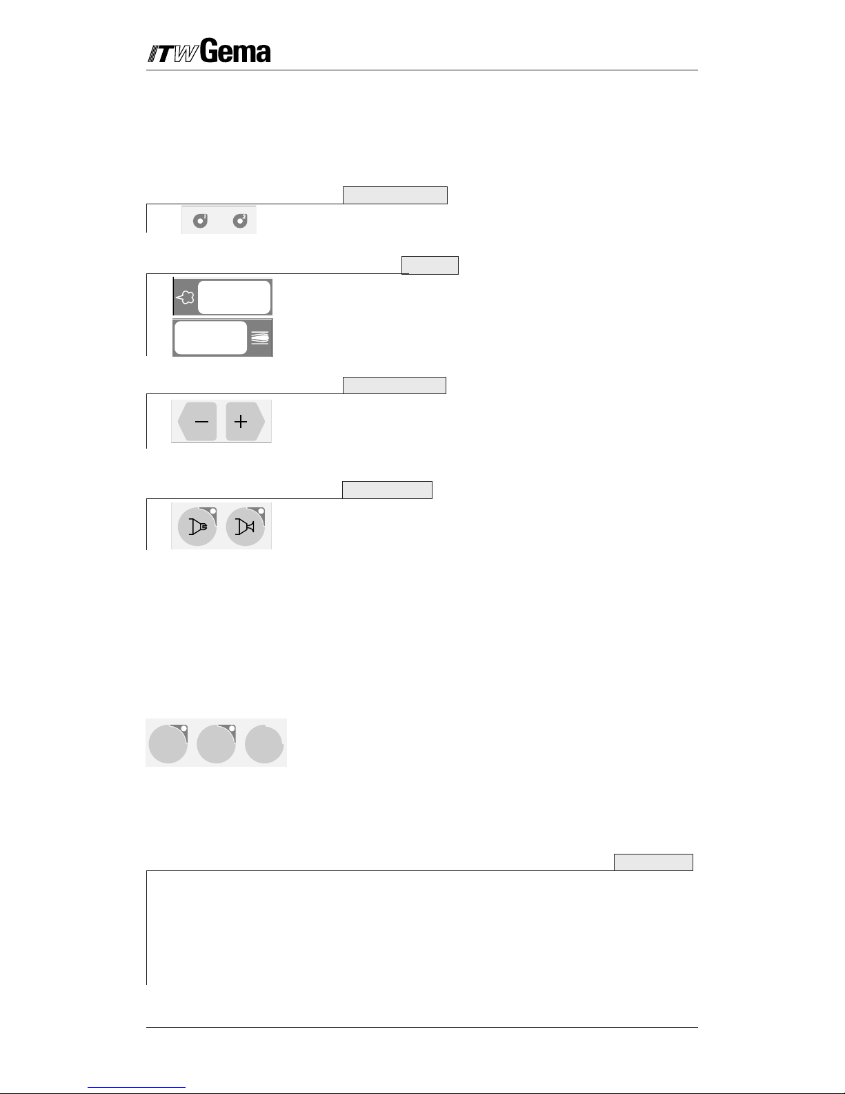
The operating panel of the EasyTronic control unit consists of 4 main
areas:
Diagnostic LEDs, Displays, "+/–" Keys, and Function keys.
1. The Diagnostic LEDs 1–8 serve to show the status of the equip-
ment, and equipment faults. Detailed information is found in the
"Troubleshooting Guide"
2. There are two Displays with whose help the following values are
displayed:
• Powder output (Setting range 0–100 %) Powder output in %
always refers to the max. possible output volume to the total
air volume setting.
• Total air volume (Setting range 1.6–6.0 Nm3/h)
3. The Keys "+" and "–" are for setting the powder output, and the
total air volume used.
If a key is pressed once, the value is increased or decreases,
respectively, by one step. If a key is pressed continuously, the
setting change rapidly.
4. The Function keys have the following functions:
• Electrode rinsing air for flat jet nozzles
• Electrode rinsing air for round jet nozzles
When a key is pressed once, the corresponding function is
activated, and the corresponding LED illuminates.
If a key with an illuminated LED is pressed for longer than 1
second, the function is deactivated.
ITW Gema recommends leaving the electrode rinsing air
switched on, but can, however, remain switched off for
applications with very small amounts of powder.
• Application keys: With these keys the electrostatic (High-
voltage, and current) are automatically set so that the setting
for the selected application is the optimum.
– Settings for flat parts
– Settings for complicated parts with depressions
– Settings for coating parts already coated
High-voltage and current can be deactivated, when the
corresponding key pad with the illuminated LED is pressed for
longer than 1 second.
The EasyTronic control unit is switched on and off with a Push button.
If the equipment is switched on, the yellow lamp is illuminated.
When the equipment is first switched on the preselected factory
settings displayed:
60% 4.0 Nm3/h
Flat jet rinsing Complicated parts
After switching the equipment off (also when the equipment is disconnected from the Mains) the actual settings are retained.
DESCRIPTION OF THE EASYTRONIC CONTROL UNIT
Figure 1
3
EasyTronic
Issued 07/02
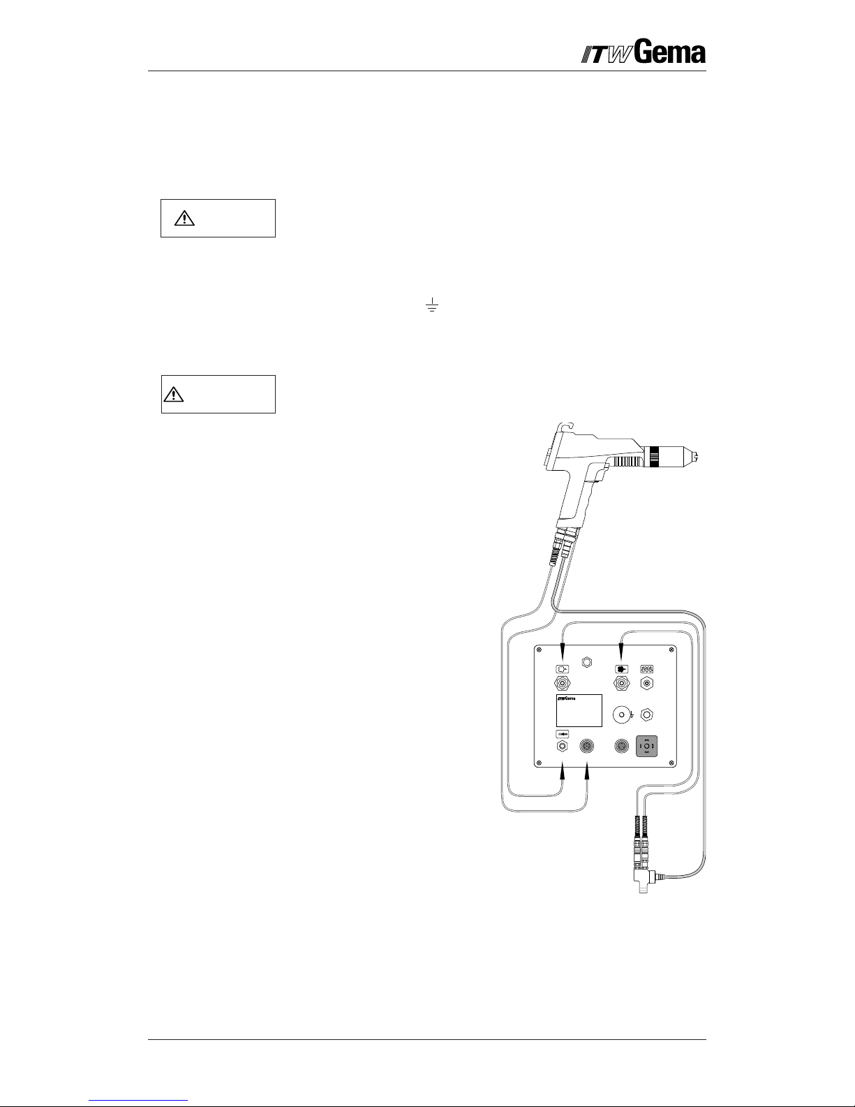
INSTALLATION OF THE POWDER COATING EQUIPMENT
1. Connect the hose for the compressed air supply from com-
pressed air circuit directly to the main air connection - 1.1 IN on
the rear of the control unit (female thread: 1/4" B.S.P.).
The compressed air must be free from oil and water.
2. Connect the black hose for the fluidizing air (if required) to the
corresponding output (1.5) on the rear of the control unit.
3. Fit the grounding connection cable on the control unit with the
grounding screw , and the 5 m long grounding cable with the
clamping clip to the booth or on the hanger device.
4. Connect the gun cable with the 7 pin plug on the rear of the
control unit on the socket - 2.2 (Gun).
PG 1 Manual powder guns cannot be connected!
5. Connect the hose for
rinsing air to the rinsing air
output - 1.4 and to the
powder gun.
6. Plug the injector in, and
connect the powder hose
to the injector and to the
powder gun.
7. Connect the red hose for
the conveying air to the
corresponding output - 1.2
on the rear of the control
unit and to the injector.
8. Connect the black hose for
the supplementary air to
the corresponding output -
1.3 on the rear of the
control unit and to the
injector.
9. Connect the Mains cable on
the socket - 2.1.
Figure 2
Mains connectionAux
Gun
1.1 IN
5 ... 10bar
73...145PSI
1.4 2.2 2.3
2.1
1.3
1.2 1.5
Input voltage:
Input power:
Degree of protection:
Output:
Corresponding guns:
85 – 264 V
47 – 440 Hz
65 VA
IP 54
10 V 1,2 A
EasySelect
POWDER GUN CONTROL
TYPE EASYTRONIC
NOTICE
IMPORTANT
 Loading...