

Page 1
ITW Dynatec
An Illinois Tool Works Company
31 V olunteer Drive
Hendersonville, TN 37075 USA
Telephone 615.824.3634
FAX 615.264.5222
Adhesive Application Solutions · ISO 9001 Certified
ITW Dynatec GmbH
Industiestrasse 28
D-40822 Mettmann, Germany
Telephone 49.2104.915.0
FAX 49.210.2104.915.1 11
ITW Dynatec K.K.
Daiwashinagawa Bldg., 7-15 Konan, 3-Chome
Minata-Ku, Tokoyo 108 Japan
Telephone 81.3.3450.5901
FAX 81.3.3450.8405
OPERATIONS & SERVICE MANUAL
Manual 20 -25
Revised 1/05
DYNAMINI
ä
ADHESIVE SUPPLY UNIT
OPERATIONS AND SERVICE MANUAL
with Software Version 2.00
For an online copy of this manual, go to www.itwdynatec.com/manuals.htm
IMPORT ANT! -READ ALL INSTRUCTIONS BEFORE OPERATING THIS EQUIPMENT
It is the customer’s responsibility to have all operators and service personnel read and understand
this information. Contact your ITW Dynatec customer service representative for additional copies.
NOTICE! Please be sure to include the serial number of your application system
each time you order replacement parts and/or supplies. This will enable us to
send you the correct items that you need.
ITW Dynatec Service Parts Direct Dial: 1- 800-538-9540
ITW Dynatec Technical Service Direct Dial: 1- 800-654-6711
Page 2

Page ii
Revised 1/05
ITW Dynatec c. 2004
DYNAMINI ASU Manual #20 -25
The Dynamini ASU is manufactured under one or more of the following PA TENTS:
United States:
D388,800 5,613,451
5,632,918 5,645,743
5,683,578 5,719,378
5,806,720
Europe:
97309164.8-2206
ITW Dynatec
An Illinois Tool Works Company
Adhesive Application Solutions
Page 3

ITW Dynatec c. 2004
DYNAMINI ASU Manual #20 -25
TABLE OF CONTENTS
Chapter 1 Safety Precautions Chapter -Page #
Chapter 2 Specifications & Dimensions
Model Description Matrix 2-1. . . . . . . . . . . . . . . . . . . . . . . . . . . . . . . . . . . . . . . . . . . . . . . . . . . . . . .
Specifications 2-2. . . . . . . . . . . . . . . . . . . . . . . . . . . . . . . . . . . . . . . . . . . . . . . . . . . . . . . . . . . . . . . .
Dimensions 2-4. . . . . . . . . . . . . . . . . . . . . . . . . . . . . . . . . . . . . . . . . . . . . . . . . . . . . . . . . . . . . . . . . .
Chapter 3 Installation & Start Up
Mounting the ASU/ Lifting the ASU 3-1. . . . . . . . . . . . . . . . . . . . . . . . . . . . . . . . . . . . . . . . . . . . . . .
Installation 3-2. . . . . . . . . . . . . . . . . . . . . . . . . . . . . . . . . . . . . . . . . . . . . . . . . . . . . . . . . . . . . . . . . .
W attageAvailabilityChart 3-4. . . . . . . . . . . . . . . . . . . . . . . . . . . . . . . . . . . . . . . . . . . . . . . . . . . . . .
Adding to or Changing the Adhesive Formula 3-4. . . . . . . . . . . . . . . . . . . . . . . . . . . . . . . . . . . . . . . .
Air Control Filter Unit/ Rear Cover: Head & Hose Connections 3-5. . . . . . . . . . . . . . . . . . . . . . . . . . .
Typical Start Up and Shut Down Procedures 3-6. . . . . . . . . . . . . . . . . . . . . . . . . . . . . . . . . . . . . . . . .
Storage and Disposal of the Application System 3-7. . . . . . . . . . . . . . . . . . . . . . . . . . . . . . . . . . . . . .
Chapter 4 Dynamini Temperature Controller Set- Up
Page iii
Revised 1/05
Temperature Control Functions in General 4-1. . . . . . . . . . . . . . . . . . . . . . . . . . . . . . . . . . . . . . . . . . .
Defining Dynamini Temperature Control Terms 4-1. . . . . . . . . . . . . . . . . . . . . . . . . . . . . . . . . . . . . . .
Error Indication Messages 4-2. . . . . . . . . . . . . . . . . . . . . . . . . . . . . . . . . . . . . . . . . . . . . . . . . . . . . . .
Software Chip (EPROM) and Checksum 4-2. . . . . . . . . . . . . . . . . . . . . . . . . . . . . . . . . . . . . . . . . . . .
Settings for a Typical Operation 4-3. . . . . . . . . . . . . . . . . . . . . . . . . . . . . . . . . . . . . . . . . . . . . . . . . . .
System V alues 4-3. . . . . . . . . . . . . . . . . . . . . . . . . . . . . . . . . . . . . . . . . . . . . . . . . . . . . . . . . . . . . . . .
Default Settings of the Controller 4-4. . . . . . . . . . . . . . . . . . . . . . . . . . . . . . . . . . . . . . . . . . . . . . . . .
Helpful Tips for the User 4-4. . . . . . . . . . . . . . . . . . . . . . . . . . . . . . . . . . . . . . . . . . . . . . . . . . . . . . . .
Chapter 5 Programming of the Dynamini Controller
Controller Keypad 5-1. . . . . . . . . . . . . . . . . . . . . . . . . . . . . . . . . . . . . . . . . . . . . . . . . . . . . . . . . . . . .
Programming 5-1. . . . . . . . . . . . . . . . . . . . . . . . . . . . . . . . . . . . . . . . . . . . . . . . . . . . . . . . . . . . . . . .
Turn On 5-1. . . . . . . . . . . . . . . . . . . . . . . . . . . . . . . . . . . . . . . . . . . . . . . . . . . . . . . . . . . . . . . . . . . . .
Temperature Setpoints 5-2. . . . . . . . . . . . . . . . . . . . . . . . . . . . . . . . . . . . . . . . . . . . . . . . . . . . . . . . . .
Turning Zones On/ Off 5-2. . . . . . . . . . . . . . . . . . . . . . . . . . . . . . . . . . . . . . . . . . . . . . . . . . . . . . . . . .
Error Indication Messages 5-2. . . . . . . . . . . . . . . . . . . . . . . . . . . . . . . . . . . . . . . . . . . . . . . . . . . . . . .
Keypad Locking 5-3. . . . . . . . . . . . . . . . . . . . . . . . . . . . . . . . . . . . . . . . . . . . . . . . . . . . . . . . . . . . . .
Service Functions 5-4. . . . . . . . . . . . . . . . . . . . . . . . . . . . . . . . . . . . . . . . . . . . . . . . . . . . . . . . . . . . .
Diagram of the Service Functions Loop 5-4. . . . . . . . . . . . . . . . . . . . . . . . . . . . . . . . . . . . . . . . . . . . .
Standby 5-5. . . . . . . . . . . . . . . . . . . . . . . . . . . . . . . . . . . . . . . . . . . . . . . . . . . . . . . . . . . . . . . . . . . . .
Tolerance 5-6. . . . . . . . . . . . . . . . . . . . . . . . . . . . . . . . . . . . . . . . . . . . . . . . . . . . . . . . . . . . . . . . . . . .
Sequential Startup 5-6. . . . . . . . . . . . . . . . . . . . . . . . . . . . . . . . . . . . . . . . . . . . . . . . . . . . . . . . . . . .
Temperature Scale 5-7. . . . . . . . . . . . . . . . . . . . . . . . . . . . . . . . . . . . . . . . . . . . . . . . . . . . . . . . . . . . .
Ready Delay 5-7. . . . . . . . . . . . . . . . . . . . . . . . . . . . . . . . . . . . . . . . . . . . . . . . . . . . . . . . . . . . . . . . .
Change Access Code 5-8. . . . . . . . . . . . . . . . . . . . . . . . . . . . . . . . . . . . . . . . . . . . . . . . . . . . . . . . . . .
Chapter 6 Preventive Maintenence
General Cleaning 6-1. . . . . . . . . . . . . . . . . . . . . . . . . . . . . . . . . . . . . . . . . . . . . . . . . . . . . . . . . . . . . .
Preventive Maintenanace 6-1. . . . . . . . . . . . . . . . . . . . . . . . . . . . . . . . . . . . . . . . . . . . . . . . . . . . . . .
Output Filter 6-1. . . . . . . . . . . . . . . . . . . . . . . . . . . . . . . . . . . . . . . . . . . . . . . . . . . . . . . . . . . . . . . . .
Hose Fittings and Fasteners 6-1. . . . . . . . . . . . . . . . . . . . . . . . . . . . . . . . . . . . . . . . . . . . . . . . . . . . . .
Page 4

Page iv
Revised 1/05
DYNAMINI ASU Manual #20 -25
Hopper Filter Inspection and Cleaning 6-2. . . . . . . . . . . . . . . . . . . . . . . . . . . . . . . . . . . . . . . . . . . . .
Purging the Filter Manifold of Adhesive and Pressure 6-2. . . . . . . . . . . . . . . . . . . . . . . . . . . . . . . . . .
Flushing the System 6-3. . . . . . . . . . . . . . . . . . . . . . . . . . . . . . . . . . . . . . . . . . . . . . . . . . . . . . . . . . .
Chapter 7 Troubleshooting
Handling Printed Circuit Boards 7-1. . . . . . . . . . . . . . . . . . . . . . . . . . . . . . . . . . . . . . . . . . . . . . . . . .
Printed Circuit Board & Layout Illustration 7-2. . . . . . . . . . . . . . . . . . . . . . . . . . . . . . . . . . . . . . . . . .
Overtemp Thermostat 7-3. . . . . . . . . . . . . . . . . . . . . . . . . . . . . . . . . . . . . . . . . . . . . . . . . . . . . . . . . .
Location of PCB & Overtemp Thermostat Re-set 7-3. . . . . . . . . . . . . . . . . . . . . . . . . . . . . . . . . . . . .
Resistance Tables 7-4. . . . . . . . . . . . . . . . . . . . . . . . . . . . . . . . . . . . . . . . . . . . . . . . . . . . . . . . . . . . .
Troubleshooting Guide 7-5. . . . . . . . . . . . . . . . . . . . . . . . . . . . . . . . . . . . . . . . . . . . . . . . . . . . . . . . .
Pump Operation & Adjustable Pressure Relief 7-9. . . . . . . . . . . . . . . . . . . . . . . . . . . . . . . . . . . . . . . .
Piston Pump Troubleshooting Guide 7-10. . . . . . . . . . . . . . . . . . . . . . . . . . . . . . . . . . . . . . . . . . . . . . .
Gear Pump Troubleshooting Guide 7-14. . . . . . . . . . . . . . . . . . . . . . . . . . . . . . . . . . . . . . . . . . . . . . . .
Chapter 8 Disassembly & Re- assembly Procedures
To Remove the Pump & Electronics Cover 8-1. . . . . . . . . . . . . . . . . . . . . . . . . . . . . . . . . . . . . . . . . .
To Remove the Hopper Cover 8-1. . . . . . . . . . . . . . . . . . . . . . . . . . . . . . . . . . . . . . . . . . . . . . . . . . . .
To Remove the Hopper Lid 8-2. . . . . . . . . . . . . . . . . . . . . . . . . . . . . . . . . . . . . . . . . . . . . . . . . . . . . .
Thermostat Replacement 8-2. . . . . . . . . . . . . . . . . . . . . . . . . . . . . . . . . . . . . . . . . . . . . . . . . . . . . . . .
RTD Sensor Replacement 8-2. . . . . . . . . . . . . . . . . . . . . . . . . . . . . . . . . . . . . . . . . . . . . . . . . . . . . . .
To Access & Replace the Electrical Components 8-3. . . . . . . . . . . . . . . . . . . . . . . . . . . . . . . . . . . . . .
To Access & Replace the Pumps or Motors 8-5. . . . . . . . . . . . . . . . . . . . . . . . . . . . . . . . . . . . . . . . . .
Note on Cast-in Heaters 8-6. . . . . . . . . . . . . . . . . . . . . . . . . . . . . . . . . . . . . . . . . . . . . . . . . . . . . . . . .
Re-assembly Procedures & Cautions 8-7. . . . . . . . . . . . . . . . . . . . . . . . . . . . . . . . . . . . . . . . . . . . . . .
ITW Dynatec c. 2004
Chapter 9 Available Options & Accessories
Pressure Gauge Kit 9-1. . . . . . . . . . . . . . . . . . . . . . . . . . . . . . . . . . . . . . . . . . . . . . . . . . . . . . . . . . . . .
Filter Option 9-1. . . . . . . . . . . . . . . . . . . . . . . . . . . . . . . . . . . . . . . . . . . . . . . . . . . . . . . . . . . . . . . . .
Pump Options & Accessories 9-1. . . . . . . . . . . . . . . . . . . . . . . . . . . . . . . . . . . . . . . . . . . . . . . . . . . . .
Troubleshooting Job Aide 9-2. . . . . . . . . . . . . . . . . . . . . . . . . . . . . . . . . . . . . . . . . . . . . . . . . . . . . . .
Recommended Service Parts List 9-3. . . . . . . . . . . . . . . . . . . . . . . . . . . . . . . . . . . . . . . . . . . . . . . . . .
Chapter 10 Component Illustrations & Bills of Material
Electrical Panel Assembly 10-2. . . . . . . . . . . . . . . . . . . . . . . . . . . . . . . . . . . . . . . . . . . . . . . . . . . . . . .
Piston Pump Assembly 10-4. . . . . . . . . . . . . . . . . . . . . . . . . . . . . . . . . . . . . . . . . . . . . . . . . . . . . . . . .
Cabinet Assembly 10-6. . . . . . . . . . . . . . . . . . . . . . . . . . . . . . . . . . . . . . . . . . . . . . . . . . . . . . . . . . . . .
Drive Section 10-8. . . . . . . . . . . . . . . . . . . . . . . . . . . . . . . . . . . . . . . . . . . . . . . . . . . . . . . . . . . . . . . . .
Filter & Melt Assembly 10-10. . . . . . . . . . . . . . . . . . . . . . . . . . . . . . . . . . . . . . . . . . . . . . . . . . . . . . . . .
Pump Assemblies 10-12. . . . . . . . . . . . . . . . . . . . . . . . . . . . . . . . . . . . . . . . . . . . . . . . . . . . . . . . . . . . . .
Chapter 1 1 System Schematics & Engineering Drawings
Hose Schematic: all models 11-2. . . . . . . . . . . . . . . . . . . . . . . . . . . . . . . . . . . . . . . . . . . . . . . . . . . . . .
Head Schematic: all models 11-3. . . . . . . . . . . . . . . . . . . . . . . . . . . . . . . . . . . . . . . . . . . . . . . . . . . . . .
W iringDiagrams 11-4. . . . . . . . . . . . . . . . . . . . . . . . . . . . . . . . . . . . . . . . . . . . . . . . . . . . . . . . . . . . . .
Page 5
ITW Dynatec c. 2004
DYNAMINI ASU Manual #20-25
Page 1-1
Revised 9/98
Chapter 1
SAFETY PRECAUTIONS
All operators and service personnel must read
and understand this manual before operating
or servicing equipment.
Electrical
DANGER
HIGH VOLTAGE
Dangerous voltages exist at several points in this
equipment. Toavoid personal injury, do not touch
exposed connections and components while input
High Temperatures
WARNING
HOT
SURFACE
All maintenance and service on this equipment must be performed by trained technicians.
power is on. Disconnect, lockout and tag external
electrical power before removing protective panels.
A secure connection to a reliable earth ground is
essential for safe operation.
A disconnect switch with lockout capability must be
provided in the line ahead of the unit. Wiringused to
supply electrical power should be installed by a
qualified electrician.
Severe burns can occur if unprotected skin comes in
contact with molten adhesive or hot application system
parts.
Safety glasses, gloves and long- sleeved clothing must
be worn whenever working with or around adhesive
application systems.
High Pressure
WARNING
HIGH PRESSURE
PRESENT
To avoid personal injury, do not operate the equipment
Protective Covers
WARNING
DO NOT OPERATE
WITHOUT GUARDS
IN PLACE
without all covers, panels and safety guards properly
installed.
To prevent serious injury from molten adhesive under
pressure when servicing the equipment, disengage the
pumps and relieve the adhesive system’s hydraulic
pressure (e.g., trigger the heads, hand-held applicators,
and/or other application devices into a waste container)
before opening any hydraulic fittings or connections.
Keep all guards in place!
To avoid personal injury, do not operate the application
system without all covers, panels and safety guards
properly installed.
Page 6
Page 1-2
Revised 3/97
Eye Protection & Protective Clothing
WARNING
ITW Dynatec c. 2004
DYNAMINI ASU Manual 20-25
Wear safety glasses with side shields which conform to
ANSI Z87.1 or EN166.
EYE PROTECTION
REQUIRED
PROTECTIVE
CLOTHING
REQUIRED
It is very important that you PROTECT YOUR EYES
when working around hot melt adhesive equipment!
Safe Installation and Operation
To avoid possible failure of hoses, make sure all hoses
are routed to avoid kinking, tight radius turns (8” or
less) and abrasive contact. Hot-melt hoses should not
have prolonged contact with heat-absorbing surfaces
such as cold floors or metal troughs. These
heat-absorbing surfaces can alter adhesive flow and
cause incorrect calibration. Hoses should never be
covered with materials that p revent heat dissipation,
such as insulation or sheathing.
Read this manual before applying electrical power to
the equipment. Equipment may be damaged by
incorrect electrical connections.
Do not use adhesive that is dirty or that may be
chemically contaminated. Doing so can cause system
Failure to wear safety glasses could result in severe eye
injury.
It is important to protect yourself from potential burns
when working around hot melt adhesive equipment.
Wear protective gloves and long-sleeved, protective
clothing to prevent burns that could result from contact
with hot material or hot components.
Always wear steel-reinforced safety shoes.
clogging and pump damage.
When adhesive hand-held applicators or other movable
applicators are used, never point them at yourself or at
any other person. Never leave a hand-held applicator’s
trigger unlocked when not actually in use.
Do not operate the hopper or other system components
without adhesive for more than 15 minutes if the
temperature is 150 degrees C (300 degrees F) or more.
To do so will cause charring of the residual adhesive.
Never activate the heads, hand-held applicators and/ or
other application devices until the adhesive’s
temperature is within the operating range. Severe
damage could result to internal parts and seals.
Treatment for Burns From Hot Melt Adhesives
Burns caused by hot melt adhesive must be treated at a
burn center.
Care should be used when working with hot melt
adhesives in the molten state. Because they rapidly
solidify,they present a unique hazard.
Even when first solidified, they are still hot and can
cause severe burns. When working near a hot melt
application system, always wear safety gloves, safety
glasses and long-sleeved, protective clothing.
Always have first-aid information and supplies
available.
Call a physician and/or an emergency medical
technician immediately.
Page 7

ITW Dynatec c. 2004
DYNAMINI ASU Manual #20-25
Service
Refer all servicing to qualified personnel only.
Explosion/ Fire Hazard
Page 1-3
Revised 9/98
Never operate this unit in an explosive environment.
Use cleaning compounds recommended by ITW
Dynatec or your adhesive supplier only.Flash points
Lockout/ Tagout
Follow OSHA 1910.147 (Lockout/ Tagout Regulation)
for equipment’slockout procedures and other important lockout/ tagout guidelines.
Be familiar with all lockout sources on the equipment.
In This Manual
WARNINGS and CAUTIONS are found throughout
this manual.
WARNINGS mean that failure to observe the specific
of cleaning compounds vary according to their composition, so consult with your supplier to determine the
maximum heating temperatures and safety precautions.
Even after the equipment has been locked out, there
may be stored energy in the application system, particularly in the capacitors within the panel box. Toensure
that all stored energy is relieved, wait at least one minute before servicing electrical capacitors.
instructions may cause injury to personnel.
CAUTIONS mean that failure to observe the specific
instructions may damage the equipment.
Page 8

Page 1-4
Revised 3/97
ITW Dynatec c. 2004
DYNAMINI ASU Manual 20-25
ITW Dynatec
An Illinois Tool Works Company
Page 9

ITW Dynatec c. 2004
DYNAMINI ASU Manual #20 -25
SPECIFICATIONS AND DIMENSIONS
DYNAMINI
5 = 5 kg/ 10 lb.
1 = 10 kg/ 20 lb.
HOSE: 2- hose capable
PUMP TYPE:
P12 = Piston Pump 12:1
GAS = Gear Pump 1.5cc
GBS = Gear Pump 3.2cc
GCS = Gear Pump 4.5cc
GDS = Gear Pump 0.55cc
GES = Gear Pump 10cc
Page 2 -1
Revised 1/05
Chapter 2
N X 2 X X X X - X X X X
VOL TAGE:
1 = 100 - 120VAC, 1 phase
2 = 200 - 240VAC, 1 phase
OPTIONS:
ACCESSORIES:
F = 100 mesh/ 149 micron outlet filter (40 mesh/ 420 micron is standard)
G = Analog pressure gauge
V = Swirl kit, 1 hose
W = Swirl kit, 2 hose
CONFIGURED SYSTEM OPTIONS:
C24 = 2.4m/ 8 ft. Abrasion resistant hose
C36 = 3.6m/ 12 ft. Abrasion resistant hose
CHB = Hand Bead Applicator
CHS = Hand Swirl Applicator
STACKTITE SYSTEM OPTIONS:
SB = Bead applicator
SS = Swirl applicator
EXAMPLE:
N52GAS2- F = Dynamini 10 lb. hopper w/ 1.5cc gear pump, 240 VAC/ 1 phase and 100 mesh outlet
filter .
DYNAMINI Model Designation Matrix
Page 10

Page 2 -2
Revised 1/05
DYNAMINI ASU Manual #20 -25
ITW Dynatec c. 2004
Specifications
Environmental:
Storage/ shipping temperature -40° C to 70°C (-40° F to 158°F). . . . . . . . . . . . . . . . . . . . . . . . . . . . . .
Ambient service temperature -7° C to 50°C (20° F to 122°F). . . . . . . . . . . . . . . . . . . . . . . . . . . . . . . .
Noise emission TBD < db(A). . . . . . . . . . . . . . . . . . . . . . . . . . . . . . . . . . . . . . . . . . . . . . . . . . . . . . . .
Physical:
Dimensions see dimensional layouts on following pages. . . . . . . . . . . . . . . . . . . . . . . . . . . . . . . . . . . .
Number of heads/ hoses 2. . . . . . . . . . . . . . . . . . . . . . . . . . . . . . . . . . . . . . . . . . . . . . . . . . . . . . . . . . .
Number of hopper temperature zones 1. . . . . . . . . . . . . . . . . . . . . . . . . . . . . . . . . . . . . . . . . . . . . . . . .
Number of pumps 1. . . . . . . . . . . . . . . . . . . . . . . . . . . . . . . . . . . . . . . . . . . . . . . . . . . . . . . . . . . . . . . .
Piston pump ratio 12:1. . . . . . . . . . . . . . . . . . . . . . . . . . . . . . . . . . . . . . . . . . . . . . . . . . . . . . . . . . . . . .
Gear pump see options on page 2-1. . . . . . . . . . . . . . . . . . . . . . . . . . . . . . . . . . . . . . . . . . . . . . . . . . .
Enclosure styled, durable metal and high temp plastic, dust and splatter resistant. . . . . . . . . . . . . . . . .
Hose connections Electrical: universal 15-pin Amphenol connectors at asu,. . . . . . . . . . . . . . . . . . . . .
Mechanical: wrench-secured fluid fittings (#6 JIC)
Hopper (tank) capacity Model 05: 5 kg/ 11 lb. . . . . . . . . . . . . . . . . . . . . . . . . . . . . . . . . . . . . . . . . . . .
Model 10: 10 kg/ 20 lb
Hopper construction cast-in heaters, TFE Teflon impregnated. . . . . . . . . . . . . . . . . . . . . . . . . . . . . .
Filtration hopper bottom screen, manifold basket filter. . . . . . . . . . . . . . . . . . . . . . . . . . . . . . . . . . . . .
Weight, empty tbd kg/ tbd lb. . . . . . . . . . . . . . . . . . . . . . . . . . . . . . . . . . . . . . . . . . . . . . . . . . . . . . . . . .
Adhesive form standard grades (non-water based only). . . . . . . . . . . . . . . . . . . . . . . . . . . . . . . . . . . .
Electrical:
Power Supply Required 100-120 VAC/ 1p/ 50-60 Hz/ 15 Ampere. . . . . . . . . . . . . . . . . . . . . . . . . . .
or 200-240 VAC/ 1p/ 50-60 Hz/ 30 Ampere
Hopper heater type cast-in tubular. . . . . . . . . . . . . . . . . . . . . . . . . . . . . . . . . . . . . . . . . . . . . . . . . . . . .
Power consumption, system maximum 100-120 VAC system: 1800 watts. . . . . . . . . . . . . . . . . . . . . .
200-240 VAC system: 6800 watts (w. piston pump)
200-240 VAC system: 7200 watts (w. gear pump)
Hopper Power 100-120 VAC system: 600 watts at 120 VAC. . . . . . . . . . . . . . . . . . . . . . . . . . . . . . .
200-240 VAC system: 1200 watts at 240 VAC
Temperature control microcontroller. . . . . . . . . . . . . . . . . . . . . . . . . . . . . . . . . . . . . . . . . . . . . . . . . . .
Temperature sensors 100 Ohm Platinum RTD standard. . . . . . . . . . . . . . . . . . . . . . . . . . . . . . . . . . . .
Gear pump Motor 1/4 hp, constant speed, AC, direct drive, horizontal orientation. . . . . . . . . . . . . . . .
Page 11

ITW Dynatec c. 2004
DYNAMINI ASU Manual #20 -25
Pressurized Air:
Air pressure supply 1.4 to 6.8 bar (20 to 100 psig). . . . . . . . . . . . . . . . . . . . . . . . . . . . . . . . . . . . . . . . .
Air consumption at 60 pump cycles per minute 90 normal liters/ minute. . . . . . . . . . . . . . . . . . . . . . .
(3.2 SCFM at 100 psig)
Performance:
Adhesive temperature control range 40°C to 218°C (100°F to 425°F). . . . . . . . . . . . . . . . . . . . . . . . .
Adhesive temperature control accuracy ± 1°C (± 1°F). . . . . . . . . . . . . . . . . . . . . . . . . . . . . . . . . . . . .
Over-temperature cutoff for hopper 232°C (450°F). . . . . . . . . . . . . . . . . . . . . . . . . . . . . . . . . . . . . . .
Adhesive viscosity 500 to 50,000 centipoise. . . . . . . . . . . . . . . . . . . . . . . . . . . . . . . . . . . . . . . . . . . . .
Warm-up time, full hopper approximately .5 hour. . . . . . . . . . . . . . . . . . . . . . . . . . . . . . . . . . . . . . . . .
Adhesive delivery rate, open line .91 kg/min (2 lb/min)(12:1 piston pump). . . . . . . . . . . . . . . . . . . . .
Adhesive melt rate (depends on adhesive used) 8 kg/hr (17.3 lb/hr). . . . . . . . . . . . . . . . . . . . . . . . . . .
Adhesive pressure up to 68 bar (1000 psi) maximum. . . . . . . . . . . . . . . . . . . . . . . . . . . . . . . . . . . . . . .
Maximum pump speed, piston pump 60 pump cycles per minute. . . . . . . . . . . . . . . . . . . . . . . . . . . . .
Maximum pump speed, gear pump 87 revolutions per minute, 60 Hz, constant speed. . . . . . . . . . . . . .
73 revolutions per minute, 50 Hz, constant speed
Page 2 -3
Revised 1/05
Dynamini Temperature Control:
Controller board 1 printed circuit board. . . . . . . . . . . . . . . . . . . . . . . . . . . . . . . . . . . . . . . . . . . . . . . . .
Display type long-life, light-emitting diode (LED). . . . . . . . . . . . . . . . . . . . . . . . . . . . . . . . . . . . . . . .
Temperature control zones 5 triac-output. . . . . . . . . . . . . . . . . . . . . . . . . . . . . . . . . . . . . . . . . . . . . . . .
Other:
Operator interface digital display with simplified, all-icon keypad. . . . . . . . . . . . . . . . . . . . . . . . . . . . .
Temperature offset no. . . . . . . . . . . . . . . . . . . . . . . . . . . . . . . . . . . . . . . . . . . . . . . . . . . . . . . . . . . . . .
Sensor open error message yes. . . . . . . . . . . . . . . . . . . . . . . . . . . . . . . . . . . . . . . . . . . . . . . . . . . . . . .
Page 12
Page 2 -4
Revised 1/05
ITW Dynatec c. 2004
DYNAMINI ASU Manual #20 -25
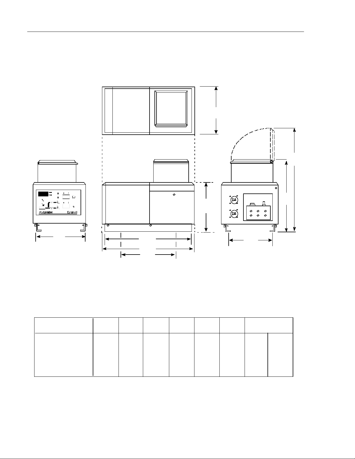
A
F
A
DIMENSION A B C D E F G H
MODEL 05 (mm)
MODEL 05 (inches)
MODEL 10 (mm)
MODEL 10 (inches)
D
B
C
H
G
mounting holes*
289 527 540 238 451 635 249 381
11.38 20.75 21.25 9.37 17.75 25.0 9.8 15.0
289 527 540 238 654 838 249 381
11.38 20.75 21.25 9.37 25.75 33.0 9.8 15.0
E
* All Mounting holes are 10mm diameter .
DYNAMINI Installation Dimensions
Page 13

ITW Dynatec c. 2004
DYNAMINI ASU Manual 20-25
Page 3-1
Revised 1/05
Chapter 3
INSTALLATION & START-UP
Mounting the DYNAMINI ASU
The DYNAMINI ASU can be mounted on most flat surfaces, on either an open or a solid frame (as
shown below). The main electrical power and the serial communication connections come in from
below the unit and connect under the keypad. Access to the underside of the ASU is not a necessary
consideration in mounting the unit.
The Dynamini’s hinged hopper lid may be rotated 90 degrees in any direction.
For installation dimensions, see illustration on page 2-4.
Lifting the ASU
Hopper Cover
WARNING
The unit must be lifted by two persons, using proper lifting technique, one
person at either end. Securely hold it under its base plate. No belts or hooks
should be used. Never allow anyone to stand on the ASU.
Hopper Lid
Access Cover
Pump & Electronics Cover
Pump ON/OFF
Switch
Main ON/OFF
Power Switch
Controller
Keypad
Captive Cover Screws
Base
Plate
Page 14
Page 3-2
Revised 1/05
DYNAMINI ASU Manual #20-25
ITW Dynatec c. 2004
Installation
NOTE: Re-read Chapter 1 “Safety Precautions” before performing any installation procedures. All
installation procedures must be performed by qualified, trained technicians.
After the DYNAMINI ASU has been properly mounted, the following general sequence should be
followed for installation:
1. Make sure that incoming line power to the ASU is turned OFF at a customer-providedcircuit
breaker. Incoming line power must be overcurrent-protected.
DANGER HIGH VOLTAGE
Disconnect and lockout input power to the application system before starting any installation procedures. Make sure there is no electrical power on the
leads you will be connecting. THE UNIT’S MAIN SWITCH DOES NOT SHUT OFF
ALL POWER WITHIN UNIT!! Make sure incoming line power is turned off at the
customer-provided circuit breaker before opening unit.
2. For 200-240 VAC units, power supply wires should be rated for 30 Amperes service and
should include an earth ground conductor.
CAUTION: Grounding conductors never carry electrical current. The use of a
neutral conducting wire as earth ground is incorrect and may cause damage to
the equipment.
3. 100-120 VAC units are supplied with a line cord and a plug suitable for use in North America
on 15 AMP power supplies. For other types of 100-120 VAC power wiring, supply wires should
be rated for 1.5 Amp service and include an earth ground conductor.
4. Acceptable power supplies are either 100-120 VAC 1-Ph 50/60 Hz with a neutral wire, or
200-240 VAC 1-Ph 50/60 Hz with or without a neutral wire. The information plate on the ASU
(adhesive supply unit) will indicate the required power supply.
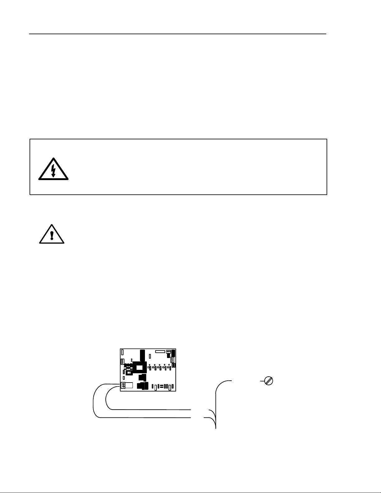
5. Power supply wires are to be connected to the removable plug at header X1 on the printed
circuit board,, as shown below.
Printed
Circuit
Board
X1
GROUND
L2/ N
L1
POWER IN
Supply Power Installation Diagram
Page 15
ITW Dynatec c. 2004
DYNAMINI ASU Manual 20-25
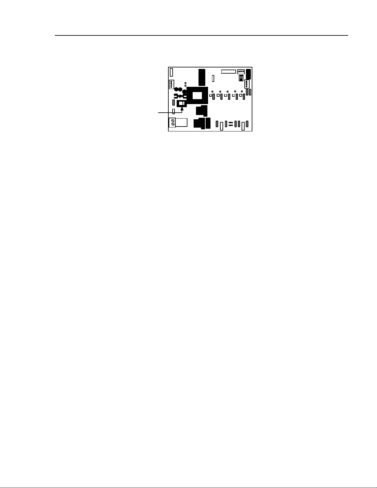
6. Choose ASU Voltage:
Using the selection switch on the printed circuit board, set the controller for the appropriate
supply voltage.
Voltage Selection Switch:
“230” for 200-240VAC
or
“115” for 100-120VAC
Printed Circuit Board
7. Reassemble the pump and electronics cover to the ASU.
8. Gear Pump models: omit this step.
Piston Pump models: Install t he Air Control/ Filter Unit (containing the air regulator,the
coalescing filter and pre-filter). See illustration on page 3-5. The air control/ filter unit is
mounted directly to the ASU via a threaded hole on the rear cover. WrapTeflon tape around
the nipple fitting before installing in the ASU. The unit requires clean, dry air. NEVER use
lubricated oil.
Page 3-3
Revised 1/05
For operator convenience, the air pressure gauge can be mounted to either side of the air
control regulator.
Withthe air pressure regulator, a clockwise turn increases pressure. A counter-clockwise
turn decreases pressure. The recommended pressure is 1.4 to 6.8 bar (20 to 100 psi).
9. Refer to the WattageAvailability Chart on the next page to determine the hose and head
power available for the various configurations of the Dynamini ASU.
10. The adhesive hoses are connected at the rear cover (see illustration on page 3-5). Make
your electrical hose connections at the two numbered connects on the left side of the cover.
Route hoses so that there is at least an eight-inch radius at any bend. Do not hang hoses
without proper support. Do not crimp, clamp, squeeze or tie hoses.
The hose adhesive ports are located at the bottom of the filter block, to the right of the
electrical connections. There are three ports for the use of up to two hoses and for the
(optional) adhesive pressure gauge.When making hose connections, use the numbered
guides shown on the illustration to coordinate; ie. when using one hose make your hookup
to electrical connection #1 and adhesive port #1. When using two heads/ hoses, hookup
hose/ head #1 to electrical connection #1 and adhesive port #1, then hookup hose/ head #2
to electrical connection #2 and adhesive port #2.
Refer to the hose and applicator manuals for further details on these items.
11.Install the hose manifold outlet cover by sliding it into place and attaching with the two M4
screws provided.
Page 16
Page 3-4
Revised 1/05
DYNAMINI ASU Manual #20-25
ITW Dynatec c. 2004
Wattage Availability Chart
Wattage Available for
All Hoses and Heads
ASU Voltage Max. System Hopper Gear Pump Piston Pump Gear Pump
Wattage Wattage Motor Wattage
100-120 VAC 1800 @ 120VAC 600 @ 120VAC 370 @120VAC 1200 @ 120VAC 830 @ 120VAC
200-240 VAC 7200 @ 240VAC 1200 @ 240VAC 370 @ 240VAC 6000 @ 240VAC 5630 @ 240VAC
Notes:
1. Assume 33 Watts per foot of hose, #6 hose at 120VAC or 240VAC.
2. Assume 100 Watts per inch of head width, at 120VAC or 240VAC.
3. The power available for any one hose or head is 720 Watts at 120VAC or 1440 Watts at 240VAC.
4. At reduced voltage, less wattage is available. For example: 120 volt equipment operated on 100
volts or 240 volt equipment on 200 volts, will develop wattage 31% lower than the wattage available
at 120 or 240 volts.
Adding Adhesive
WARNING HOT ADHESIVE
Do not overfill the hopper (melt tank) since adhesive generally expands as it
melts and a full hopper will overflow.
CAUTION: Using adhesive with viscosity over 50,000 centipoise could cause
motor stall and/ or pump failure.
The adhesive level should be maintained at 13mm to 100mm (1/2” to 4”) from the top of the hopper. Where applications demand a high output volume of adhesive, add small amounts of adhesive
frequently. Adding large amounts of adhesive to an almost empty hopper will lower the temperature
of the adhesive in the hopper and may cause the ASU to fall below its READY setpoint.
Changing the Adhesive Formula
If a different adhesive formulation from the one being currently used is needed, the system will
have to be flushed if the two formulations are incompatible. See page 6-3 of this manual for the
proper flushing procedure. When in doubt about adhesive compatibility, flush your system.
Page 17

ITW Dynatec c. 2004
DYNAMINI ASU Manual 20-25
Pressurized Air In
1/4 NPT female
Air pressure gauge
Page 3-5
Revised 1/05
Air Pressure Regulator (clockwise increases)
Air Flow
Coalescing filter
Air Control/ Filter Unit
Maintain adhesive level 13mm-100mm (1/2”4”) from top of hopper.
Pre-filter
Adjustable Pressure
Relief Valve
Air Control/ Filter Unit
Hose/ Head
Electrical Connections
120v 240v
Electrical #1
Electrical #2
Electrical #1
Electrical #2
Rear Cover: Hose and Head Electrical and Adhesive Connections
Output Filter Manifold
Adhesive Supply
Hose
Pressure Gauge (optional)
Hose/ Head Adhesive Ports
Adhesive Port Connections
#1
Gauge
#2
Page 18

Page 3-6
Revised 1/05
DYNAMINI ASU Manual #20-25
ITW Dynatec c. 2004
Typical Start-Up and Shut Down of the DYNAMINI Application System
Start Up Procedures
1. Fill the ASU’shopper with clean hot-melt adhesive as described on page 3-4. Close the
hopper lid immediately to prevent contaminants from falling in. (Cover your bulk supply of
adhesive to prevent contaminants also.)
2. At the control panel, turn ON the Main Power Switch. The controller will perform its initial
calibration cycle. The display will read “CAL”. Each of the five temperature zone’s LEDs will
flash as a lamp test.
3. Program your adhesive setpoints (see instructions on page 5-2) or use the factory settings listed
below. Allow adequate time (approximately 20-30 min.) for the adhesive to melt and the
temperatures of the temperature zones to stabilize.
Note: When the ASU leaves the ITW Dynatec factory, it is programmed with the following
factory settings (unless special factory settings were requested):
Hopper: 150°C (300°F)
Hose: 177°C (350°F)
Applicator: 177°C (350°F)
Sequential Startup: ON
4. Once the ASU has reached temperature, turn ON the Pump ON/ OFF Switch. The ASU will
begin to pump adhesive.
5. a. On piston pump units: use the air pressure regulator, located at the rear of the ASU, to
regulate adhesive output.
b. On gear pump units: use the pressure relief valve, located on the filter outlet manifold, to
regulate adhesive output.
Shut Down Procedures
1. Turn OFF the Pump Switch.
2. Turn OFF the Main Power Switch.
Page 19

ITW Dynatec c. 2004
DYNAMINI ASU Manual 20-25
Revised 1/05
Storage and Disposal of the DYNAMINI Application System
Temporary Storage of the Unit
1. Flush the adhesive application system with flushing fluid (PN L15653), following the
instructions detailed in chapter 6 of this manual.
2. Clean or replace both the output filter and the primary filter, following instructions detailed
in chapter 6.
3. Shut OFF all pressure and power sources.
4. Release residual air pressure.
5. Remove all residual adhesive and wipe components clean.
6. Remove all air lines and all power supply cables.
Page 3-7
7. Pack the unit in a corrosion-proof manner.
8. Store the unit in such a way that it is protected from damage.
Disposal of the Unit
1. Shut OFF all pressure and power sources.
2. Release residual air pressure.
3. Remove all residual adhesive.
4. Remove all air and adhesive supply hoses and all power supply cables.
5. Dismantle all components and sort into mechanical and electrical components.
6. Arrange for all components to be recycled.
Page 20

Page 3-8
Revised 1/05
ITW Dynatec c. 2004
DYNAMINI ASU Manual #20-25
ITW Dynatec
An Illinois Tool Works Company
Adhesive Application Solutions
Page 21

ITW Dynatec c. 2004
DYNAMINI ASU Manual #20-25
Page 4-1
Revised 11/04
Chapter 4
DYNAMINI TEMPERATURE CONTROLLER SET-UP
Temperature Control Functions in General
The Dynamini temperature controller provides accurate temperature control for the hopper, hoses
and applicators. Setpoints are programmed at the user-friendly,all-icon keypad. The controller will
display an error message any time an open or shorted sensor condition occurs.
Defining Dynamini Temperature Control Terms
Adhesive Temperature Control Range
The temperature limits within which the ASU, hoses and applicators may be programmed and maintained.
Printed Circuit Board (PCB)
The Dynamini contains one pcb. It contains the central processing unit (CPU) of the microprocessor
temperature control as well as providing control signals to, and monitoring signals from, the hopper,
hoses and applicators. It features lighted LEDs to indicate that heater power is ON. The ASU’s fuses
are located on this board.
Dynamini Temperature Controller
The built-in control system that controls, monitors and displays all system temperature values of the
Dynamini adhesive application system.
Mechanical High-Temperature Protection
A mechanical, redundant thermostat located on the hopper that will turn off t he system above 232°C
(450°F).
RTD Sensors
The Dynamini system uses 100-ohm platinum resistance temperature detector sensors for all temperature controls.
Sequential Startup
This feature allows the temperature zones to come on in sequence (hopper,followed by hose, followed by head). When activated, and the ASU is turned ON from a cold start, the hopper heats first.
When the hopper is within the programmable tolerance of setpoint, the Head(s) and hose(s) begin to
heat. No other features of the ASU are affected by sequential startup.
Note: sequential startup is rarelyused. In most cases, it should be de-activated to ensure rapid warm
up.
Page 22
Page 4-2
Revised 1/05
Setpoint
DYNAMINI ASU Manual #20-25
ITW Dynatec c. 2004
A programmable temperature that has been selected for hopper, hoses and applicators.
Setpoint Limitation
This is a universal maximum temperature for all zones (218°C [425°F]). The programmer cannot
program a temperature setpoint higher than the setpoint limitation.
Stepped Function
(Future feature, not on V2.0)
Used on systems with electric applicators only. After programming the temperature (to the softening
point of your adhesive, see your adhesive manufacturer), the controller holds all electric heads at
the operator-selected temperature for ten minutes before releasing them to operating setpoint. This
feature allows for the stabilization of the electric valves.
Error Indication Messages
A controller display of “EO1” indiates that the selected zone (ie, a hose, applicator or the hopper)
has an open sensor. A display of “EO2” indicates a shorted sensor.
If either alarm occurs, first verify that the following three connections are made correctly:
1. The ASU-to-hose connection(s) located at the back of the ASU,
2. The hose-to-applicator connection(s),
3. The RTD Input connections (X4) located on the Control Printed Circuit Board.
If the problem is not with a connection, check the sensor and replace if necessary.
Software Chip (EPROM) and Checksum
The software EPROM is on the Control Printed Circuit Board (see Ch. 7). Inscribed on the controller’s software chip is information that is required if your controller needs service, including the controller’schecksum.
Software chip example:
Part Number of
Control PCB
The date this Software EPROM was manufactured
102434 OEF8
Date: 12-7-04
Software chip (EPROM)
Checksum example
Page 23

ITW Dynatec c. 2004
DYNAMINI ASU Manual #20-25
Settings for a Typical Operation
Note: The values given here are approximate settings for a typical packaging operation. The values
you choose will be based on the type of equipment and adhesive you are using and the nature of
your particular operation.
If Application Temperature is 163°C (325°F):
·
Hose and head temperature: 177°C (350°F).
·
Hopper setpoint temperature: 150°C (300°F).
·
ASU operating range: 135°C to 177°C (275°F to 350°F).
·
Mechanical thermostat (for the hopper) over-temperature: 232°C (450°F)
Page 4-3
Revised 11/04
System Values That Are Permanently Programmed
·
Minimum setpoint value: 40°C (100°F).
·
Maximum setpoint value: 218°C (425°F).
System Values as Programmed by the Factory
ITW Dynatec can set the controller’s system values to customer’s specs, if provided.
If customer’s specs are not provided, the following values will be entered into the Dynamini tem-
perture controller at the factory. They may be changed by reprogramming through the keypad.
(These are not the “default” settings, see following section).
·
Temperature scale: displayed in degrees Farenheit.
·
Applicator (head) and hose setpoints: 177°C (350°F).
·
Hopper setpoint: 150°C (300°F).
·
All zones are switched off, except for the hopper.
Page 24

Page 4-4
Revised 1/05
Default Settings of the Controller
Default settings are the manufacturer’s preset values to which the system will return if the Dynamini tempearture control is subjected to an internal memory reset. While you can change your programmed values to anything within the system’s limits, the default settings cannot be changed.
To cause an internal memory reset (ie, to restore the defaults) of a temperature zone, turn that temperature zone ON and then OFF.
Defaults
·
Temperature setpoint for each zone: 93°C (200°F).
·
Sequential Startup: SSO (OFF)
Helpful Tips for the User
DYNAMINI ASU Manual #20-25
ITW Dynatec c. 2004
·
When the ASU is turned on, all temperature setpoints and other operating parameters will
be exactly where they were when the ASU was turned off.
·
When the ASU is turned on, all system heaters go on unless they have previously been set
below 40°C (100°F).
Page 25
ITW Dynatec c. 2004
DYNAMINI ASU Manual #20-25
PROGRAMMING INSTRUCTIONS FOR DYNAMINI CONTROLLER
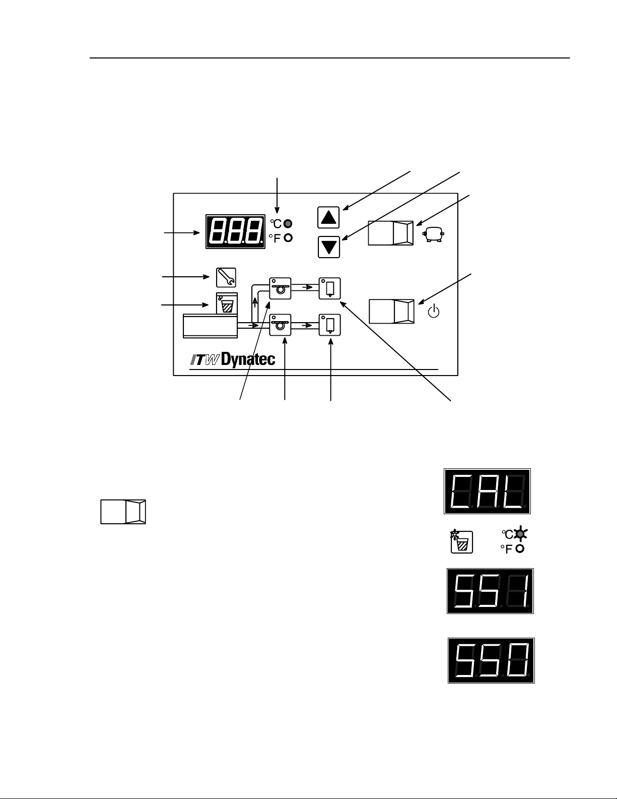
Dynamini Keypad
Page 5-1
Revised 1/05
Chapter 5
Scroll Keys:
Pump Switch
O
Main Power Switch
O
Temperature
Display
Service Key
Hopper
Temperature
Zone
Temperature
Scale
1
1
22
to increase value to reduce value
I
I
Dynamini
Temperature Zones: Hose #1 Hose #2 Application Head #2 Application Head #1
Programming
Turn controller ON
O
I
Turn ON the main power switch.
System will go through its self-diagnostics (CAL).
Temperature zone LEDs will flash.
Controller will display “SS 1” (On) or “SS 0” (Off) to
indicate status of the Sequential Statup feature
(see info on “Sequential Startup” later in this chapter).
Controller will display it’s software version, ie.
V.2.XX
or
Page 26
Page 5-2
Revised 1/05
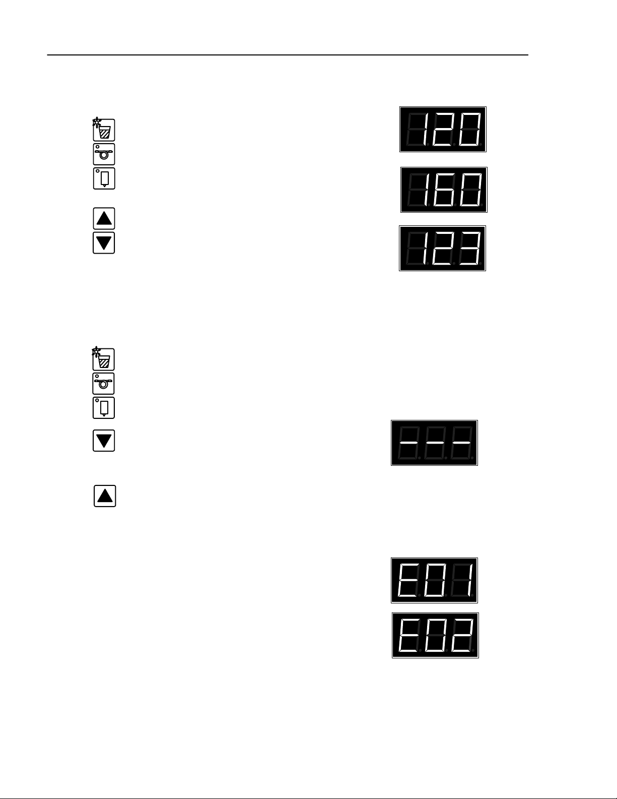
Programming temperature setpoints
ITW Dynatec c. 2004
DYNAMINI ASU Manual #20-25
or
Choose a temperature zone.
or
Scroll to “increase value” or ”reduce value”,
or
in order to adjust the setpoint temperature.
After two seconds the display will read the
actual temperature. The setpoint is stored.
Turning temperature zones ON/OFF
or
Choose a temperature zone.
or
Scroll to “reduce value” until temperature
setpoint is 0. The temperature zone is now
turned OFF.
To turn ON the temperature zone, increase
the setpoint.
Error indication messages
The temperature sensor is open or has high resistance.
The temperature sensor is shorted or has low resistance.
Page 27
ITW Dynatec c. 2004
DYNAMINI ASU Manual #20-25
Keypad Locking
Page 5-3
Revised 1/05
Itis possible to lockorunlock the controller inorderto restrict programming changes.Tochange the
code which is necessary to over-ride or unlock the keypad lock, see Service Functions.
Note: the ASU is shipped with de-activated keypad lock. If the keypad lock must be used, an access
code must be programmedprior to locking the keypad.
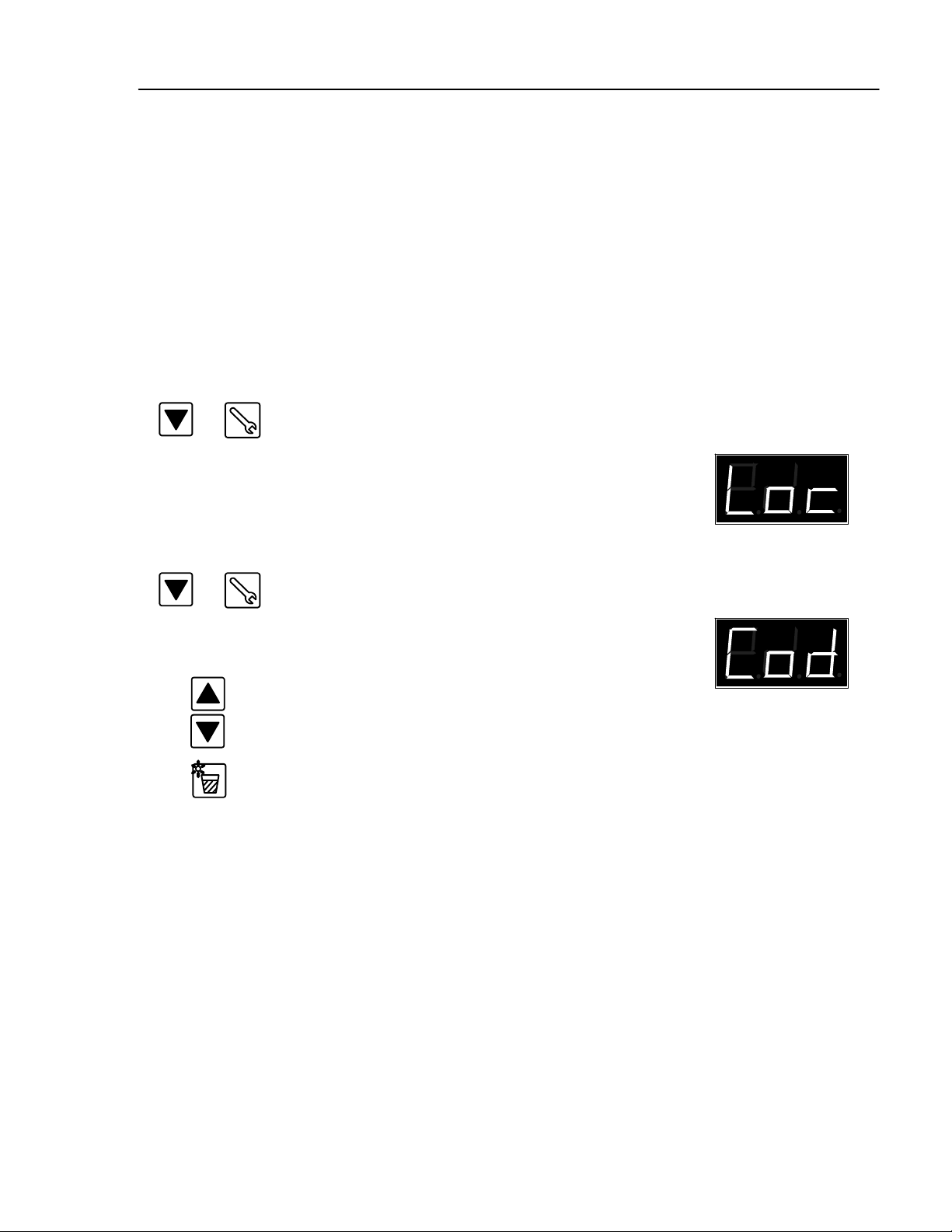
Locking or Unlocking the Keypad
Important Note: the controller must be in the Temperature Display mode in order to allow
locking or unlocking of the keypad.
Locking the Keypad
&
Unlocking the Keypad
&
or
Press the Down Scroll key, then hold and press the
Serviceiconkey.
You will see “Loc” to indicate that the Keypad Lock is
active.
Press the Down Scroll key, then hold and press the
Serviceiconkey.
You will see “Cod” to indicate that the access code is
required.
Enter your access code by scrolling up or down. Default
co de = “ -- -- -- ”.
Confirm your code input by pressing Tank key.
Notes:
1. Once the keypad lock is active, unauthorized programming is not possible, even after turning the
ASU OFF, then back ON again.
2.Once the keypad lockisunlocked,programming is possibleuntiltheASUis turnedOFF,then back
ON or the keypad is locked again.
3.Ifthekeypadmust be unlocked permanently,theaccesscodemust must be de-activatedin the Service Functions.
Page 28

Page 5-4
Revised 1/05
DYNAMINI ASU Manual #20-25
ITW Dynatec c. 2004
Service Functions
After the basic programming of TemperatureSetpoints is complete, the programmer proceeds to
programming of the Service Functions, if desired.
The Service Functions are a continuous loop of programming steps (”functions”) which the programmer moves through by pressing the “Service” key. These steps are described in this section
of the chapter. The Service Functions loop and b asic programming is diagrammed below.
There are three ways to exit the Service Functions loop:
1. Just wait (approx. 10 seconds) and the controller will automatically return to the actual temperatures display,
2. Press the Service key until you are back to the actual temperatures display, or
3. Press any Hose or Head key and you will return to the actual temperatures screen.
Diagram of the
Service Functions Loop
C
F
Actual Temperature Display
Activate De-activate Temperature Setback
Change Setback Temperature Value
Change Hi/ Lo Tolerance Value
Activate/ De-activate Sequential Startup
Select Temperature Scale
Change Ready Delay
Change Access Code
C
F
Actual Temperature Display
Page 29

ITW Dynatec c. 2004
DYNAMINI ASU Manual #20-25
Page 5-5
Revised 1/05
Service Functions
Standby Programming
, cont.
“Standby” is a temperature value by which all temperature zones will lower when Standby mode
is activated. For example, if your temperature setpoints are all 300 degrees, and you program a
100 degree Standby, then the Standby temperature of all zones will be 200 degrees. Similarly, if
your temperature zones setpoints vary, and you program a 100 degrees Standby,each zone’s
Standby temperature will be 100 degrees lower than its setpoint.
Press Service icon to enter Service Functions.
You will see either “S--1” (standby is On) or “S--0”
(standby is Off).
Press the Tank icon to activate/ de-activate Standby.
If desired, you may set the Standby temperature by
scrolling up or down to desired temperature.
When programming is complete, wait a few seconds
and the controller will return to the ASU’s actual
temperature.
or
Note: When Standby is active, the display will alternate between the ASU’sactual temperature
and S--1.
Page 30

Page 5-6
Revised 1/05
ITW Dynatec c. 2004
DYNAMINI ASU Manual #20-25
Service Functions,
T o Set Tolerance (Hi & Low Temperature Limits)
cont.
The Tolerance (high/ low alarm) setpoint is a range (+ and -- the zone’s temperature setpoint) between which your ASU can safely operate. It’s lower temperature represents the ASU’sready
temperature. It’s upper value represents the over-temperature point.
Setting the Tolerancerange, for example: if the temperature setpoint is 200 degrees, and the Tolerance setpoint is 10 degrees, then the high alarm (overtemp) equals 210 degrees and the low alarm
(ready temp) equals 190 degrees.
x2
or
Press the Service icon twice to select the Tolerances of your
temperature zones. An display of “t--1” indicates the Tolerance
function has been selected.
Press the Tank button to display the Tolerance.
Use the scroll buttons to change the Tolerance range for all zones.
Note: your Tolerance range must be a value between ± 50 degrees
for Fahrenheit (± 27 degrees for Celsius).
When Tolerance programming is complete, wait a few seconds and
the controller will return to the ASU’s actual temperature.
Turning Sequential Startup ON/OFF
The Sequential Startup feature programs the order in which the temperature zones will come on at
startup. A Sequential Startup” of “SS1” (On) means the tank will begin heating first, then, when the
tank is ready, the other zones will begin heating. A Sequential Startup of “SSO” means Sequential
Startup is Off and all zones will begin heating immediately.
x3
or
Press the Service icon three times to set Sequential Startup.
The display will flash either “SS1” (sequential startup is ON) or
“SS0” (sequential startup is OFF).
Scroll to choose between ON and OFF. When programming is
complete, wait a few seconds and the controller will return to
the ASU’s actual temperature.
Note: Any time the ASU is switched ON, you will briefly see
“SS1” or “SS0” displayed.
or
Page 31

ITW Dynatec c. 2004
DYNAMINI ASU Manual #20-25
Page 5-7
Revised 1/05
Service Functions,
To Set Temperature Scale
cont.
The Temperature Scale may be set to display temperature either in degrees Celsius or Fahrenheit.
x4
or
To Set Ready Delay
Press the Service icon four times to set the Temperature
Scale.
Scroll to choose between Celsius (”C”) or Fahrenheit
(”F”) as indicated by the Temperature Scale LED. When
programming is complete, wait a few seconds and the
controller will return to the ASU’s actual temperature.
When the system is ready (all temperature zones are within tolerance), a ready delay may be programmed to delay the system’s ready output signal.
x5
Press the Service icon five times to set a Ready Delay.
You will see “d--1” to indicate you are in Ready Delay
programming mode.
or
Press the Tank icon to display the Ready Delay.
To change a Ready Delay, scroll up or down to the
desired length (in minutes) of delay.
0 = Default, no delay
99 minutes = maximum length of delay
When programming is complete, wait a few seconds and
the controller will return to the ASU’s actual temperature.
Page 32

Page 5-8
Revised 1/05
ITW Dynatec c. 2004
DYNAMINI ASU Manual #20-25
Service Functions,
cont.
To Change Access Code (De-activate Keypad Locking)
x6
To change the Access Code, press the Service icon six
times.
You will see “C--1” to indicate you are in Access Code
programming mode.
Press the Tank icon to see the programmed Access
Code. For example, “999”.
To change the Access Code, scroll up or down to the desired
or
numeric value.
“-- -- --” = no Access Code (Access code is de-activated),
“-- -- --” = no Keypad Locking
1 - 999 = possible Access Code values
When programming is complete, wait a few seconds and the controller will return to
the ASU’s actual temperature.
Page 33

ITW Dynatec c. 2004
DYNAMINI ASU Manual #20-25
Page 5-9
Revised 1/05
Controller Features
System Ready Indicator Light
When not in programming mode, a flashing temperature scale light
(LED) indicates that the ASU is not “Ready” forproduction. This LED
will cease to flash when all temperature zones are within the programmed temperature tolerance window.
Error Indication Messages
“EO1” = the temperature sensor is open (no sensor attached) or has
high resistance.
“EO2” = the temperature sensor is shorted or has low resistance.
To Copy and Paste Setpoints
The Copy/ Paste feature of the controller copies the tank setpoint and pastes it as the setpoint of
other temperature zones. The paste will apply to only temperature zones that are switched ON.
then
Set your Tank setpoint as described earlier in this chapter.
&
&
Push and hold the Tank icon. While holding, press the #1 Hose icon. Release.
Push and hold the Tank icon again. While holding, press the #1 Head icon. Release.
The manually programmed setpoint has now been pasted in to all turned on hose and
head zones. When programming is complete, wait a few seconds and the controller
will return to the ASU’s actual temperature.
Page 34

Page 5-10
Revised 1/05
ITW Dynatec c. 2004
DYNAMINI ASU Manual #20-25
ITW Dynatec
An Illinois Tool Works Company
Adhesive Application Solutions
Page 35

ITW Dynatec c. 2004
DYNAMINI ASU Manual #20-25
Page 6-1
Revised 1/05
Chapter 6
PREVENTIVE MAINTENANCE
Note: Re-read Chapter 1 “Safety Precautions” before performing any maintenance procedures. All
maintenance procedures must be performed by qualified, trained technicians.
General Cleaning
Follow the manufacturer’s directions when using industrial cleaners on the enclosure.
Preventive Maintenence
Output Filter
During the first weeks of operation, the output filter must be replaced monthly.
To replace the output filter:
1. Follow instructions “Purging the Filter
Filter Nut
Manifold of Adhesive and Pressure”, page 6-2.
2. Unscrew and remove the filter nut
(15.8 mm or 5/8” nut).
3. With pliers, pull the filter basket out.
4. Replace the o-ring on the filter nut. Apply
o-ring lubricant (PN N07588) to the new
o-ring.
5. Replace the filter basket.
6. Apply anti-seize to the threads of the filter
nut and re-install. Tighten the filter nut until
it is seated firmly, taking care not to cut the
o-ring.
Hose Fittings & Fasteners
Periodically check all hose fittings and screws for tightness.
O-ring
Filter Basket
Output Filter
Manifold
Purge Screw
Purge Drain (on underside)
Page 36

Page 6-2
Revised 1/05
Hopper FIlter Inspection & Cleaning
DYNAMINI ASU Manual #20-25
ITW Dynatec c. 2004
The hopper filter is a coarse screen located in the bottom of the hopper. It fits over the hopper’s
drain hole and prevents any large debris from leaving the hopper.
1. Pump all adhesive out of the ASU.
2. Open the hopper lid and inspect the hopper filter.
3. If cleaning the filter is necessary,lower the temperature of the hopper 20-30°C (35-50°F)
from operating temperature.
WARNING HOT SURFACE
The ASU will still be hot during this procedure. Use insulated gloves and
protective clothing when handling the hopper filter.
4. Use a hook to pull the hopper filter out.
Hopper
Filter
5. Emerse the clogged filter in flushing fluid (PN L15653),
then use a hot air gun and rags to clean it.
6. Re-insert the filter into the hopper.
7. Refill the hopper and resume production.
Purging the Filter Manifold of Adhesive and P ressure
As a safety precaution, purge the filter manifold before changing the output filter or before removing any of the hoses or applicators from their manifold port.
Refer to the illustration on page 6-1 while following these instructions.
WARNING
HIGH PRESSURE
During the purging procedure, hot adhesive can come out of the manifold under
high pressure. Wear safety glasses, gloves and protective clothing. Stand clear
of the ASU until all pressure is relieved.
HOT ADHESIVE
Avoid splashing hot adhesive. Position a heat -resistant container under the
manifold’s purge drain before proceeding.
1. The system should be at operating temperature. Turn the pump/ motor OFF.
2. With a hex key screwdriver (allen wrench), slowly loosen the purge screw (do not remove
it). Allow the adhesive and pressure to escape. All the adhesive will flow into the heatresistant container.
3. Re-tighten the purge screw.
Page 37

ITW Dynatec c. 2004
DYNAMINI ASU Manual #20-25
Page 6-3
Revised 1/05
Flushing the System
Contaminated adhesive, accumulation of residue, or changing the adhesive formulation may require
the system to be flushed. At least 6 liters (1.5 gallons) of flushing fluid is required (PN L15653).
WARNING
The flushing fluid will splash easily. Wear protective clothing, gloves and
goggles to prevent severe burns.
1. Pump out as much of the molten adhesive as possible.
2. Reduce the pump pressure to zero by first turning the pump switch to OFF. Then open the
purge screw,following the instructions given in “Purging the Filter Manifold of Adhesive
and Pressure” on page 6-2.
3. Disconnect one of the supply hoses’ adhesive feed from its applicator head. Do not
disconnect electrical power to the head. Put the hose in a secured position within a container
to catch the used flushing fluid.
4. Add flushing fluid to the hopper and allow approximately fifteen minutes for it to reach
hopper temperature. Carefully stir the flushing fluid to mix with any remaining adhesive.
5. For Piston Pumps: Slowly turn the air pressure regulator clockwise.
ForGearPumps:Slowly turn the pressure relief control valve clockwise.
6. Pump about half of the fluid into the container.
7. For Piston Pumps: Turn the regulator counter-clockwise.
ForGearPumps:Turn the motor OFF.
Pressure
Regulator
Pressure
Relief Valve
8. Remove the output filter and replace the basket. Install a new o-ring on the filter nut
(lubricate the new o-ring with o-ring lubricant prior to installation) and tighten the brass nut.
9. Add new adhesive to the hopper and heat to application temperature.
10. For Piston Pumps: Slowly turn the air pressure regulator clockwise.
ForGearPumps:Turn the motor ON.
11. Actuate each applicator until all flushing fluid is removed and a steady stream of new
adhesive flows.
12. For Piston Pumps: Re-adjust the pump air pressure for desired flow.
ForGearPumps:Re-adjust the pressure relief for desired flow.
13. Re-fill the hopper and resume production.
Page 38

ITW Dynatec c. 2004
DYNAMINI ASU Manual #20-25
Page 7-1
Revised 1/05
Chapter 7
TROUBLESHOOTING
General Troubleshooting Notes
Note: Re-read Chapter 1 “Safety Precautions” before performing any troubleshooting or repair procedures. All troubleshooting or repair must be performed by qualified, trained technicians.
DANGER
HIGH VOLTAGE
Dynamini systems use electrical power that can be life threatening and hot-melt adhesives that
can cause serious burns. Only qualified persons should perform service on the Dynamini system.
Handling Printed Circuit Boards (PCBs)
WARNING
HOT SURFACE
DANGER HIGH VOLTAGE
Before unplugging connectors from the I/O PCBs, ground yourself to the
ASU by touching any available unpainted cool metal surface, mounting
screws, etc. This will avoid electrical discharge to the PCB assembly when you are removing and replacing connectors.
CAUTION: Printed circuit boards (PCBs) should b e handled using the following
procedures:
1. Wear a wrist grounding strap. If a grounding strap is not available, frequently touch a
bare metal part of the ASU (unpainted frame, mounting screw, etc.) to safely discharge
any electrostatic buildup on your body.
2. Handle a PCB by its edges only. Don’t grip a PCB across its surface.
3. When removed from the ASU, each PCB must be individually packaged inside a
metallized, static drain envelope. Do not place the removed PCB on a table, counter,
etc. until it has first been placed in or on a static drain envelope.
4. When handing a PCB to another person, touch the hand or wrist of that person to
eliminate any electrostatic charge before you hand the PCB to him.
5. When unwrapping a PCB from its static drain envelope, place the envelope on a
grounded, nonmetallic surface.
6. To cushion PCBs for shipment, use only static-drain bubble pack. Do not use foam
peanuts or bubble pack not known to be static draining.
Page 39

Page 7-2
Revised 1/05
DYNAMINI ASU Manual #20-25
ITW Dynatec c. 2004
Printed Circuit Board
Notes:
The PC board contains the controller’s software/ CPU chip and non-volatile memory.
The green, temperature zone LEDs cycle on and off as each heater outputs.
The PCB is mounted under the ASU’s cover.
The fuses are designated F1 thru F13 below. See diagram for sizes. The fuses are the only replace-
able parts on the pc board. Each temperature zone is fused with two fuses.
Connect to RTDs:
1&2 = Hopper
3&4 = Hose 1
5&6 = Head 1
7&8 = Hose 2
9&10 = Head 2
Over Temp
{
Thermostat
PCB fuse
(1A slow)
Connect to
Main Switch
Customer’s
Power Input
Software/
CPU chip
10
1
X4
LED1 (5v OK)
LED2 (12v OK)
X3
230v
F1
Transformer
for Dynatec
use
J1
54321
LED3 LED4
F2 F3 F4 F5
HOSE1 HEAD1 HOPPER HOSE2 hEAD2
Relay
1
X2
HOSE1 HEAD1 HOSE2 HEAD2
X1
N
Relay
L
F9
Connect to
Keypad at J1
X5
Hopper
LED5
F10
HOPPER
X9
X10
Ready
No Com NC
X6
S4
S3
S2
S1
ON
LED6 LED7
F12F11
Dip switches:
not used
Pump
X7
N
L
2 pump fuses
(2A slow)
F7 F8
F6
Temperature
zone fuses,
2 per zone
(6.3A fast)
F13
X8X11
11
Voltage Selector:
“230” = 200-240v
“115” = 100/120v
Ground
Terminal (2)
Layout of Components on PC Board
Mounting
Holes (2)
Heater RTD for
Hose/ Head 1
Mounting
Bracket/
Heat Sink
Heater rtd for
Hose/ Head 2
Connect to
Hopper Heater
Page 40

ITW Dynatec c. 2004
DYNAMINI ASU Manual #20-25
Page 7-3
Revised 1/05
Overtemp Thermostat
The overtemp thermostat is a safety back-up. If the hopper temperature exceeds 232°C (450°F), the
thermostat causes a circuit breaker to open and power to the hopper and all hoses and heads will be
cut off. The overtemp thermostat re-sets when the hopper temperature falls below 204°C (400°F).
To re-set, turn the main power switch OFF, then ON again.
Heater
PCB Board
Control PC Board
Sensor
Overtemp Thermostat
Overtemp Thermostat
Location of Printed Circuit Boards and Overtemp Thermostat
Page 41

Page 7-4
Revised 1/05
Resistance Tables
ITW Dynatec c. 2004
DYNAMINI ASU Manual #20-25
Temperature Resistance
°
F
°
CinOhms
32 0 100
50 10 104
68 20 108
86 30 112
104 40 116
122 50 119
140 60 123
158 70 127
176 80 131
194 90 135
212 100 139
230 110 142
248 120 146
268 130 150
284 140 154
302 150 157
320 160 161
338 170 164
356 180 168
374 190 172
392 200 176
410 210 180
428 220 183
Hose Length Resistance in Ohms
Meters Feet 120V 240V
1.2 4 102-125 400-490
1.8 6 63-77 291-355
2.4 8 50-61 204-249
3 10 39-48 155-189
3.7 12 31-37 125-153
4.9 16 23.6-29 98-120
7.3 24 N.A. 61-75
Nominal Hose Heater Resistance
for DynaFlex Hoses
Watts Resistance in Ohms
120V 240V
200 72 288
270 53 213
350 41 165
500 29 115
700 N.A. 82
Temperature Sensor Resistance
Note: Resistance is measured at ambient temperature (20
Nominal Head Heater Resistance
Qty. Heaters
Resistance in Ohms
for each heater
2
25
Nominal Hopper Heater Resistance
°
C/ 68°F).
Page 42

ITW Dynatec c. 2004
DYNAMINI ASU Manual #20-25
Troubleshooting Guide
Preliminary Checks: Verify the following before proceeding
1. The ASU is switched on.
2. The ASU is supplied with power.
3. The ASU is supplied with pneumatic air.
4. Pneumatic and electrical connections are correct.
5. Adhesive is in the hopper.
Error Messages (see also Chapter 4)
EO1 = temperature zone has an open sensor
EO2 = temperature zone has a shorted sensor
Hose/ Applicator Troubleshooting Tip
Hose or applicator problems can be isolated by electrically connecting the
applicator and hose to an alternate socket on the ASU. If the malfunction
goes with the applicator and hose, the problem will usually be in the applicator
or hose that was moved. If the malfunction does not move with the applicator
and hose, the problem is probably in the ASU.
Page 7-5
Revised 1/05
Problem Possible Cause Solution
Controllersetpointsare
1.Main Power switch OFF.
1.Switch ON.
not adjustable.
All channels display
2.PCB inoperative.
3.Keypad locked.
1.PCB inoperative.
2.Replace PCB.
3.Unlock.
1.Replace PCB.
errormessage orwrong
actual temperatures.
System is not working,
display is OFF.
1.Power supply plug at X1
is not plugged in.
1.Check power supply plug
connection.
2.Ribbon connector J1 is
disconnected from back
2 Check connection.
of PCB or display panel.
Display
Panel
3.F1 fuse on the PCB is
inoperative.
J1 ribbon connector to display panel
3.Insert new fuse, if it blows, the
PCB is inoperative.
F1
X2
Incoming AC power
X1
ON
Page 43

Page 7-6
Revised 1/05
Problem Possible Cause Solution
ITW Dynatec c. 2004
DYNAMINI ASU Manual #20-25
Hopper temperature is
higher than setpoint
(overtemp).
X4
Display for Hopper =
EO1.
Display for Hopper =
EO2.
1.Hopper sensor not fully
inserted.
2.Hopper sensor (X4)
inoperative.
ON
3.Inoperative PCB.
1.Plug connection X4 on
PCB is loose.
2.Temperature sensor inoperative.
1.Hopper sensor short circuit.
1.Check hopper sensor.
2.Replace hopper sensor if resistance does not comply with resistance table.
3.Replace PCB.
1.Restore connection.
2.Replace sensor if resistance does
not comply with resistance table.
1.Replace sensor if resistance does
not comply with resistance table.
Hopper does not heat,
but LED is ON.
Heater
25 Ohms
25 Ohms
2.Shortcircuitat plugconnectionX4onPCB.
3.Inoperative PCB.
1.Hopperfuses(F4&F11)
inoperative on PCB.
2.Hopper heater element
is inoperative.
3.Disconnectioninhopper
heater circuit.
4.Inoperative PCB.
2.Check and eliminate short circuit.
3.Replace PCB.
1.Insert new fuse(s) and observe
ASU. If fuse(s) blows again, check
for a short circuit in heater.
2.Replace hopper if element’sresistance does not comply with resistance table. Note: remove wires
fromboth heater elements when
measuring.
3.Check and repair (see wiring diagram).
4.Replace PCB.
Page 44

ITW Dynatec c. 2004
DYNAMINI ASU Manual #20-25
Problem Possible Cause Solution
Page 7-7
Revised 1/05
Hopper does not heat,
and LED is OFF.
Hose (or Head) is not
heating. Hose (or
Head) LED on the
PCB is ON.
Fuses:
F2 & F9 = Hose 1
F3 & F10 = Head 1
F5 & F12 = Hose 2
F6 & F13 = Head 2
1.Inoperative Control PCB.
1.Disconnection between
ASU and Hose (or
between Hose and Head).
2.Hose (or Head) fuse(s) on
the PCB is inoperative.
3.Loose plug connection on
PCB.
4.Heating element inoperative.
1.Replace PCB.
1.Check plug connections.
2.Insert new fuse(s). If fuse blows
again, check for a short circuit in
heater.
3.Check connectors X8 and X11
and restore connection.
4.Check resistance and compare to
resistance table.
a. For head: if heater cartridge
is inoperative, replace heater.
b. For hose: if heating element
is inoperative, replace hose.
Hose (or Head) is not
heating. Hose (or
Head)LED on thePCB
is OFF.
Hose (or Head) actual
temperature is much
higher than setpoint.
1.Inoperative PCB.
2.Sequential Startup is
active.
1.Inoperative Hose (or
Head) triac on PCB
(corresponding PCB LED
is OFF).
2.Inoperative Hose (or
Head) temperature sensor
(corresponding PCB LED
is ON).
1.Replace PCB.
2.Wait until hopper has reached
setpoint or re-program the heat-up
mode (see pg. 5-6).
1.Replace PCB.
2.Check resistance and compare to
resistance table.
a. For head: if sensor is
inoperative, replace sensor.
b. For hose: if sensor is
inoperative, replace hose.
Page 45

Page 7-8
Revised 1/05
Problem Possible Cause Solution
ITW Dynatec c. 2004
DYNAMINI ASU Manual #20-25
Display for Hose (or
Head) = EO1
ASU Socket
&
Hose Plug
Sensor
Heater
Plug
Sensor &
Heater
1.No Hose (or Head) is
connected.
2.Disconnection between
ASU and Hose (or between Head and Hose).
3.Disconnection at X4 on
PCB.
4.Hose(orHead)sensoris
inoperative.
1.Connect Hose (or Head) if needed. If not needed, ignore display.
2.Check plug connection.
3.Make proper connection.
4.Check resistance and compare to
resistance table.
a. For head: if sensor is
inoperative, replace sensor.
b. For hose: if sensor is
inoperative, replace hose.
Display for Hose (or
Head) = EO2
1.Hose (or Head) sensor
short circuit.
2.Shortcircuitinplugconnection between ASU
and Hose (or between
Hose and Head).
3.Inoperative PCB.
1.Check resistance and compare to
resistance table.
a. For head: if sensor is
inoperative, replace sensor.
b. For hose: if sensor is
inoperative, replace hose.
2.Make proper connection.
3.Replace PCB.
Page 46

ITW Dynatec c. 2004
DYNAMINI ASU Manual #20-25
Page 7-9
Revised 1/05
Pump Operation & Adjustable Pressure Relief
When the ASU’s hopper reaches setpoint, the controller places the hopper in “Ready” condition and
power is supplied to the pump.
An adjustable pressure relief valve is located on the output filter manifold.
When adhesive pressure exceeds the set limit, adhesive flows back to the hopper .Therefore, the
greater the setting on the pressure relief valve, the greater the adhesive output.
To change the setting of this valve, loosen the lock nut and turn the adjustment screw clockwise to
increase pressure or counterclockwise to decrease pressure. The relief valve is factory set at 27 bar
(400 psi) for gear pumps and 68 bar (1000 psi) for piston pumps.
Normally Closed (Unrelieved):
In the drawing below, the valve
is closed.
Open (Relieved):
In this drawing, pressure has
exceeded the setting of the valve,
causing the valve to open and
discharge adhesive to the hopper.
Adjustment screw
Lock nut
Mounting nut
return to
hopper
from
pump
to
hose
Adhesive flow through
filter block to hose
from
pump
Adhesive flow through
filter block to hose
Operation of the Adjustable Adhesive Pressure Relief Valve
to
hose
Page 47

Page 7-10
Revised 1/05
Piston Pump Troubleshooting Guide
ITW Dynatec c. 2004
DYNAMINI ASU Manual #20-25
WARNING
Some of the p rocedures in the following Troubleshooting G uide require working
near hot adhesive. Be sure to wear protective gloves, safety glasses and clothing
and use proper tools for handling hot melt components.
Problem Possible Cause
Pump WillNot Stroke 1.No air pressure.
Relief
Valve
Regulator
2.3-way solenoid valve is
closed.
HOT SURFACE & ADHESIVE
Solution
1.Verify system has been provided
with at least 0.5 SCFM of air at
20-100 PSIG (.014 std. cubic meters/
minute at 6.8 bar).
2.Verify that valve is properly connected (electrically) inside ASU.
Verify that valve is properly connected to Air Control/ Filter Unit.
Disconnect valve electrical leads
and verify that air is passed through
when 240 VAC is applied to the
valve terminals. Replace valve if
defective.
Solenoid
Air fittings
Air Tubes
Air
valve
3.Fault in compressed air
fitting on ASU.
4.Hopper temperature
not ready.
5.Inoperative air valve (on
back end of pump air
cylinder).
6.Inoperative air cylinder
4-way solenoid valve.
7.System is not ready.
3.Inspect the system for improper
connections, loose tubing or fittings, or kinked tubing. Repair or
replace tubing or fittings as
necessary.
4.Air valve cannot pass air until hopper
has reached setpoint window. Wait until
this has occurred. Check also the
programming of the ready time delay.
The default for this is “0”.
5.Remove air valve from pump.
Inspect, clean and repair as necessary.
6.Remove 4-way valve. Inspect,
clean and repair as necessary.
7.Wait until temperature scale (F/C) light
is steady ON (not flashing).
Page 48

ITW Dynatec c. 2004
DYNAMINI ASU Manual #20-25
Page 7-11
Revised 1/05
Problem Possible Cause
Pump Quick-Strokes in 1.No adhesive in hopper.
Both Directions
2.Adhesive too cold to flow
into pump.
3.Adhesive used is too
viscous.
4.Pump needs priming.
Loosen
set screw
Open
drain
Inlet check valve
5.Problem with pump shaft
piston.
Solution
1.Verify that hopper has an adequate
level of hot melt adhesive.
2.Check ready temperature to
make sure there has been enough
time for the adhesive to rise to the
hopper setpoint temperature.
3.Verify that adhesive selection and
hopper setpoint temperature are
compatible and that both are
appropriate for your application.
4.Prime the pump by first lowering the
air pressure, then letting the pump
cycle very slowly until primed.
5.Remove the shaft and piston from
the pump. See Chapter 8 for disassembly/ assembly procedures.
Verify that piston diameter is
correct: 19.63mm to19.66mm
(0.773” to 0.774”) and that piston is
tightly assembled to end of shaft.
Outlet
check valve
6.Large opening in system
downstream of pump.
Pump Quick-Strokes 1.Inlet check valve blocked
on the Forward-Stroke open.
Only (shaft moving
into pump body)
6.Inspect system for open filter drain,
disconnected or ruptured hose, or
disconnected head. Repair as
necessary.
1.Clean inlet check valve. This may
be possible without removing the
pump by cleaning debris through
the pump inlet hole at bottom of
hopper.
Page 49

Page 7-12
Revised 1/05
ITW Dynatec c. 2004
DYNAMINI ASU Manual #20-25
Problem Possible Cause
Pump Motion on the 1.Outlet check valve is
Forward Stroke (shaft blocked closed.
moving into pump) is
very slow or stopped.
Pump Quick-Strokes on 1.Outlet check valve is
the Reverse Stroke blocked open.
(shaft moving out of
pump)
Low or Inconsistent 1.Output filter clogged.
Adhesive Output
Inlet check valve
2.Adhesive used is too
Outlet
check valve
viscous.
Solution
1.Clean outlet check valve.
1.Clean outlet check valve.
1.Remove and inspect output filter.
Clean or replace as necessary.See
Chapter 6 “Preventive Maintenance”
for procedure.
2.Verify that system components are
at proper temperature and that
selected adhesive is correct for your
application.
3.Blocked hose.
Output
filter
4.Blocked applicator heads.
5.Pressure relief valve in
output block is opening.
Output
Manifold
Adhesive Leak at 1.Filter drain valve not
Filter Drain Spout tightly closed.
Loosen
set screw
2.Filter drain valve blocked
open.
3.Inspect hose for kinks, internal plugs
of debris or char (degraded adhesive).
Clean or replace hoses as required.
4.Inspect heads for plugged nozzles,
proper air valve operation or plugged
filters. Clean or repair heads as
needed.
5.Verify that air supplied to pump is
less than 6.8 bar (100 PSIG). If
relief valve is opening with air pressure less than 6.8 bar (100 PSIG),
remove pump and replace pressure
relief valve.
1.Close and tighten filter drain valve.
2.Remove filter plug assembly from
output manifold, clean and re-install.
Open
drain
Page 50

ITW Dynatec c. 2004
DYNAMINI ASU Manual #20-25
Page 7-13
Revised 1/05
Problem Possible Cause
Adhesive Leak at Pump 1.Pump seal out of proper
Shaft S eal position inside air motor
assembly.
Seal assembly
2.Seal inoperative.
Adhesive Leak at Pump- 1.Pump assembly nuts
Mounting Block missing or loose.
Interface
2.Inoperative mounting
block o-ring(s).
Solution
1.Remove seal from air motor and in
spect it. Replace worn or damaged
seal. Be sure there are no burrs or
other sharp edges on pump shaft or
on installation tools that could dam
age the new seal.
2.Remove seal from air motor and in
spect it. Replace worn or damaged
seal. Be sure there are no burrs or
other sharp edges on pump shaft or
on installation tools that could dam
age the new seal.
1.Verify that both pump nuts are
tightly assembled to the pump
mounting block thru the base plate
with the proper hi-collar washer.
2.Inspect the three o-rings and replace
if worn or damaged. Be sure there
are no burrs or other sharp edges in
the o-ring grooves or on installation
tools that could damage a new seal.
O-rings
Tighten
3.Helicoil insert pulled out
of hopper.
3.Remove pump and inspect bottom
of hopper. Repair or replace hopper
as necessary.
Page 51

Page 7-14
Revised 1/05
Gear Pump Troubleshooting Guide
ITW Dynatec c. 2004
DYNAMINI ASU Manual #20-25
WARNING
Some of the p rocedures in the following Troubleshooting G uide require working
near hot adhesive. Be sure to wear protective gloves, safety glasses and clothing
and use proper tools for handling hot melt components.
Problem Possible Cause
HOT SURFACE & ADHESIVE
Pump doesn’t operate. 1.Motor on/off is off at the
controller keypad.
2.Hopper temperature is
below setpoint window.
3.No incoming electrical
power.
4.System is not ready.
Solution
1.Check keypad switch.
2.Pump cannot operate until hopper has
reached ready condition. Verify that
hopper has reached ready. Re-program
hopper operating setpoint and tolerance
(hi/low) if necessary.
3.Check to see if ASU temperature
control is operating. If not, check
for presence of incoming supply
voltage.
4.Wait until temperature scale (F/C) light
is steady ON (not flashing).
Pump runs but there is 1.ASU is out of adhesive.
no adhesive output.
2.If pump has been serviced
and motor leads reversed,
pump will run with no
output.
Low or inconsistent 1.Filter(s) clogged.
adhesive output.
Hopper screen
2.Adhesive used is too
viscous.
Output
filter
3.Clogged hose.
4.Clogged applicators.
1.Add adhesive to hopper.
2.Check motor wiring to schematic.
1.Remove and inspect filter basket and
hopper screen.
2.Verify that system components are
at appropriate temperatures and that
the selected adhesive is correct for
the application.
3.Inspect hose for kinks or internal
plugs of debris or char. Clean or
replace hoses as necessary.
4.Inspect applicators for plugged
nozzles or filters. Clean or repair
applicators as necessary.
Output Manifold
Page 52

ITW Dynatec c. 2004
DYNAMINI ASU Manual #20-25
Page 7-15
Revised 1/05
Problem Possible Cause
Pressure
relief valve
5.The adjustable pressure
relief valve is opening.
Adhesive leak at pump 1.Pump seal is incorrectly
shaft seal. positioned inside the seal
and bearing assembly.
Seal assembly
2.Pump seal inoperative.
Adhesive leak at pump- 1.O-ring in pump’s rear
to-hopper interface. plate is inoperative.
Solution
5.When fully closed (clockwise) and
all applicators are off, adhesive
pressure should be around 68 bar
(1000 psi). If it is significantly less,
the pressure relief valve should be
replaced.
1.Remove seal and bearing from pump.
Verify that all components are
correctly positioned.
2.Remove seal from pump, inspect it
and replace it if worn or damaged.
Be sure there are no burrs or other
sharp edges on pump shaft or on
installation tools that could damage
a new seal.
1.Remove seal from pump, inspect it
and replace it if worn or damaged.
Be sure there are no burrs or other
sharp edges in the o-ring groove or on
installation tools that could damage
a new seal.
Pump
Rear Plate
o-ring
2. Pump assembly screws
are missing or loose.
3.Helicoil insert pulled out
of hopper or pump
interface plate.
2.Verify that all four pump screws are
tightly assembled to the pump
mounting block.
3.Remove pump and inspect bottom
of hopper. Repair or replace hopper or
pump mounting block as necessary.
Page 53

Page 7-16
Revised 1/05
ITW Dynatec c. 2004
DYNAMINI ASU Manual #20-25
ITW Dynatec
An Illinois Tool Works Company
Page 54

ITW Dynatec c. 2004
DYNAMINI ASU Manual #20-25
Page 8-1
Revised 1/05
Chapter 8
DISASSEMBLY & RE-ASSEMBLY PROCEDURES
Disassembly Procedures
Note: Re-read Chapter 1 “Safety Precautions” before performing any disassembly procedures. All
dissassembly procedures must be performed by qualified, trained technicians.
When needed, cross-reference the exploded-view component drawings in Chapter 10 with each procedurein addition to the instructions and illustrations given in this chapter. Read the
“Cautions” on page 8-7 beforere-assembling the ASU.
To Remove the Pump & Electronics Cover
(See illustration on page 10-7)
1. Loosen the four captive screws (two on each
side) along the bottom of the pump and electronics cover.
2. Lift the cover s traight up and out of its slots
in the base.
To Remove the Hopper Cover
(See illustration on page 10-7)
1. Loosen the two captive screws along the
bottom of the hopper cover.
2. Remove the access cover screw, then lift the
access cover out of its slots in the base.
3. Remove the screw that attaches to the heat
shield.
4. Remove the two screws that attach the back
panel to the hopper cover.
5. Lift the hopper cover up and out of its slots
in the base.
Pump & electronics cover
Captive screw
Hopper cover
Pump access cover
Captive screw
Page 55

Page 8-2
Revised 1/05
To Remove the Hopper Lid
(See illustration on page 10-7)
1. Remove the four flat head screws which are
located one on each side of the lid base.
2. Pull the lid up to remove.
a.
Lid Seal Replacement:
The lid seal (o-
ring) is located inside the lid base.
1. Remove the old seal, which rests against the
top of the hopper.
2. Install the new seal into the groove pro-
vided.
Thermostat Replacement
(See illustration on pages 10-7.)
1. Remove the access cover screw.
2. Lift the access cover out of its slots in the
base.
Overtemp Thermostat Replacement:
1. Remove the two screws and slip the termi-
nals and the hopper ground wire off of the
thermostat.
2. Remove the thermostat from the base of the
hopper.
3. Install new thermostat with two secrews and
re-install the terminals and hopper ground
wire.
ITW Dynatec c. 2004
DYNAMINI ASU Manual #20-25
Lid
Lid base
Lid seal
Sensor
Overtemp
RTD Sensor Replacement
Thermostat
(See illustration on page 10-11)
1. Remove the pump and electronics cover. The RTD sensor is centered between the cast-in heat-
ers on the base of the hopper.
2. Slip the sensor out of its adapter.
3. Unplug the sensor wires from pins 1 and 2 on the Control PCB (see PCB illustration on page
7-5).
Page 56

ITW Dynatec c. 2004
DYNAMINI ASU Manual #20-25
To Access the Electrical Components
(See also illustrations on pages 10-3 & 8-2)
Remove the pump and electronics cover.
Main On/ Off Switch Replacement:
a.
Note: thereare two main switches (pump
and ASU).
Switches are located on the display panel.
1. From the back of the switch, free it by
squeezing it from either side.
2. Remove the switch through the back of the
panel.
3. Disconnect four color-coded plug-in leads
from the old switch and connect them to new
switch.
b.
Fuse Replacement:
Note: Use fuses as specified on page 7-2.
i. Fuses on PC Board:
(see also detailed
illustration on page 7-2 sizes and locations of
fuses). Note on PCB fuses: each temperature
zone is fused w ith two fuses, either one of
which can blow causing the zone to not heat.
Page 8-3
Revised 1/05
Control (Keypad) Board
Pump
On/Off
Switch
ASU
On/Off
Switch
PC Board
c.
Diode Replacement:
The diode slides
onto a screw on the panel divider. Tighten
down the two screws.
Note: only the 100-120VAC ASU has a
diode.
Control (Keypad) Board Replacement:
d.
1. Disconnect electrical connections to the
printed circuit board and main switch.
2. Remove the four screws in the control
board’s corners to remove the board.
Fuses
Diode (on 100-120
VAC model only)
Page 57

Page 8-4
Revised 1/05
d.
Printed Circuit Board Replacement:
DYNAMINI ASU Manual #20-25
ITW Dynatec c. 2004
Reference the manual section entitled “Handling P rinted Circuit Boards” on page 7-1 before proceeding.
1. Disconnect the ground spade on the pcb’s mounting bracket.
2. Disconnect all electrical connections to the board.
3. Remove the two mounting bracket screws.
4. Lift the old pcb and mounting bracket from the ASU.
Note: Do not attempt to separate the pcb from its mounting bracket. It is all one assembly.
5. Place the new pcb and mounting bracket in the ASU.
6. Re-install the two mounting bracket screws.
7. Re-install the ground spade on mounting bracket.
8. Re-install electrical connectors onto the board (refer to pg. 7-2, if necessary).
Remove bracket screws (2)
Remove ground spade
Page 58

ITW Dynatec c. 2004
DYNAMINI ASU Manual #20-25
PUMP DISASSEMBLY WARNINGS
HOT SURFACE
If the pump is not operable but the heating system will function, raise the
temperature of the application system to the operating temperature to aid in the
pump disassembly process. Otherwise, a controlled heating method is
recommended to melt hardened hot melt adhesive. Never use a torch or an open
flame on any of the components of the application system.
HIGH VOLTAGE
Once the system is up to temperature, disconnect and lockout all incoming
power before proceeding.
HIGH PRESSURE
BEFORE PERFORMING ANY PUMP REPAIR, YOU MUST PURGE ALL ADHESIVE
AND PRESSURE FROM THE DYNAMINI SYSTEM. Position a heat-resistant
container under t he filter manifold’s purge drain. Carefully loosen the purge
screw located in the port of the outlet filter manifold and allow adhesive and
pressure to escape. See page 6-2 for detailed instructions.
Page 8-5
Revised 1/05
T o Access the Pump or Motor
(See illustrations on page 10-9 or 8-1)
Remove the pump and electronics cover.
a.
Piston Pump Removal:
1. Turn OFF air pressure, then disconnect the
air line from the solenoid valve mounted on
the top of the airmotor.
2. Disconnect the two wires that run from the
solenoid to the circuit board.
3. Loosen set screw to drain excess glue from
filter manifold.
4. Remove the two socket head cap screws that
connect the filter manifold to the pump adapter.
5. Remove the three screws that hold the pump
to the pump adapter.
6. Remove the pump/ airmotor assembly from
the end of the unit.
7. To re-assemble: Replace three o-rings be-
tween pump & pump adapter and filter manifold and pump adapter. Tightenthe three
pump adapter screws to the pump. Torque
should be approximately 22.6 Nm (200 in/lb)
at room temperature. With pump and hopper at
177°C (350°F), the maximum allowable torque
on pump assembly screws is 44 Nm (32.4 ft/
lb). A Piston Pump Rebuild Kit is available.
Disconnect airline from solenoid at the quick
disconnect fitting
Remove screws
to release piston
pump from
adapter.
Permanent
retaining
screw.
Loosen
set screw.
O-rings
Filter manifold
Adhesive drains from below manifold.
Remove two screws to
release filter manifold.
Piston Pump
Page 59

Page 8-6
Revised 1/05
b.
Gear Pump and Motor Removal:
1. Disconnect the motor’s electrical cable
from the ASU by unplugging it at the circuit
board
2. Remove the bolts and lockwashers which
connect the motor to the base of the unit.
3. Remove the two set screws located in the
coupling.
4. Loosen the coupling and lift out the motor.
5. To replace the gear pump, remove the four
nuts that hold the pump to the pump adapter
block.
6. Disconnect the coupling.
7. Remove the pump assembly from the end
of the unit.
8. For re-assembly: slide new pump onto the
four studs. Tightenthe four nuts to secure the
pump. Torque should be approximately 21
Nm (15 ft/lb) at room temperature. With
pump and hopper at 177°C (350°F), the maximum allowable torque on these nuts is 41 Nm
(36 ft/lb).
c.
Gear Pump Seal (O-ring) Replacement:
1. Remove the pump from the ASU (see
instructions above, “a” or “b”).
2. Remove the external pump seal (PN
069X064) from its groove on the back of the
pump adapter plate (this is the seal located
between the adapter plate and the hopper).
Reference the pump exploded-view illustration in Chapter 10 for your specific pump.
3. Install the new seal.
Gear Pump Shaft Seal Replacement:
d.
Remove the shaft key and the four socket
head cap screws holding the seal retainer
plate. The seal (069X061) is located between
the retainer plate and the front plate assembly.
ITW Dynatec c. 2004
DYNAMINI ASU Manual #20-25
Gear Pump
to base
Capacitor Disconnect from terminal rail.
Motor mount
bracket
Shaft Seal
Shaft Key
Remove nuts to
release pump
from adapter.
Disconnect from terminal
rail
Motor bracket
screws
Remove set
screws to loosen
coupling.
Remove nuts to
release pump
from adapter.
Motor bracket screws
Remove set
screws to loosen
coupling.
Retainer plate
Front plate
assembly
O-ring
069X064
Note on the Cast-in Heaters
(See illustration on page 10-11)
The cast-in heaters installed in the base of the
hopper are not replaceable and will last the
life of the ASU.
RED
BROWN
ORANGE
BLACK
7
Capacitor
WHITE
BLUE (120v)
BLUE (240v)
JUMPER (120v)
3
Gear Motor Wiring Diagram
240vac: Blue Wire in
Terminal Block, No
other Jumpers used.
120vac: Blue Wire in
Capacitor, Jumper
between Terminal
Blocks.
Page 60

ITW Dynatec c. 2004
DYNAMINI ASU Manual #20-25
Page 8-7
Revised 1/05
Re-Assembly Procedures
Unless noted, the ASU’s re-assembly is simply the reverse sequence of the disassembly procedures.
However,the following “cautions” should be followed (whenever they apply) for proper re-assembly:
CAUTION: In general, all O-RINGS AND SEALS must be replaced whenever
hot-melt equipment is re-assembled. All new o-rings must be lubricated with
o-ring lube (PN N07588).
CAUTION: TAPERED PIPE THREADS are found on air line fittings used with the
pump air supply and on the outlet filter manifold. Apply thread sealant (PN
N02892) whenever tapered pipe threaded parts are re-assembled.
CAUTION: SOME FITTINGS used for adhesive on the ASU have straight threads
and o-ring seals. Use of thread sealant is not necessary with these parts, but the
o-ring seals should be clean and lubricated. Tighten straight-threaded parts and
fittings until their shoulders are firmly seated. Excessive torque may damage
straight-threaded parts and the use of power wrenches is not recommended.
CAUTION: HOT-MELT RESIDUE must be cleaned from parts before they are
re-assembled, particularly from threaded parts. As a precaution against adhesive
residue preventing proper re-assembly, threaded parts must be re-tightened at
operating temperature.
Page 61

Page 8-8
Revised 1/05
ITW Dynatec c. 2004
DYNAMINI ASU Manual #20-25
ITW Dynatec
An Illinois Tool Works Company
Page 62

ITW Dynatec c. 2004
DYNAMINI ASU Manual #20-25
Page 9-1
Revised 1/05
Chapter 9
AVAILABLE OPTIONS & ACCESSORIES
Pressure Gauge Kit: PN 101175
An optional analog pressure gauge can be mounted on the outlet filter manifold. Reading the adhesive pressure at the manifold, rather than in-line on a hose, allows for more precise monitoring of
system pressure. It is also useful for troubleshooting and maintenance.
The gauge is installed at one of the adhesive ports on the manifold (see illustration on page 3-5).
There is no “dedicated” port for the gauge, any one of the three ports on the manifold may be used.
Fittings, o-rings and a plug are included in the kit.
Filter Option:
40 Mesh Outlet Filter: PN 101246
Some situations do not call for a fine mesh outlet filter.A “clean” adhesive or one with a long pot
life are examples. Systems utilizing lower temperatures or systems running in a clean environment
can also utilize a 40 mesh filter. Standard equipment on Dynamini is a 100 mesh filter (PN 101247).
Pump Options and Accessories:
12:1 Piston Pump: PN 105072 (120v) or 105073 (240v)
The ASU is available with a constant-pressure, air-operated piston pump. It provides smooth output
pressure and insures a high pressure adhesive output from a low pressure, compressed air input. A
piston pump is superior for intermittent applications which require no volumetric control.
Piston Pump Repair Kit: PN 105328
The Piston Pump Repair Kit contains the following items needed to rebuild the 12:1 piston pump:
PN Description Qty. PN Description Qty.
L16569 Bearing & Shaft Seal Kit 1 N00183 O-ring, 016 1
108772 O-ring, Adapter Plate 1 N01614 O-ring, 910 1
108700 Lube, Seal, 1/4 oz. 1 N00190 O-ring, 024 1
N01703 Fitting 3 N01702 O-ring, 904 3
N01618 Fitting 1 N00187 O-ring, 020 1
N07121 Ring, Seal, 111 1 069X270 O-ring, 025 1
Piston Pump Rebuild Kit: PN 109969
This kit contains a PN 105328 Pump Repair Kit, a PN 109968 Pump & Airmotor Seals Kit, a
L16534 Pump Shaft, a L21189Inlet Check Valve Assembly and a L21188 Outlet Check Valve Assembly.
Piston Pump Bearing and Shaft Seal Kit: PN L16569
This kit contains all items needed to replace the piston pump’s shaft seal and bearing, including
seals, o-ring, pump shaft bearing and retaining ring. A seal pedestal and o-ring lubricant are also
included.
Page 63

Page 9-2
Revised 1/05
Gear Pumps
DYNAMINI ASU Manual #20-25
ITW Dynatec c. 2004
For higher tolerances and precision, a choice of gear pumps is available for the Dynamini. Gear
pumps give better service for continuous applications or applications which require more control
over the volume of adhesive pumped. Gear pumps available are:
PN 109908: 0.55cc/rev single, standard accuracy,cast iron Gear Pump
PN 100860: 1.54 cc/rev single, standard accuracy Gear Pump
PN 100861: 3.2 cc/rev single, standard accuracy Gear Pump
PN 100862: 4.5 cc/rev single, standard accuracy Gear Pump
PN 109690: 10 cc/rev single, standard accuracy Gear Pump
Gear Pump Repair Kit: PN 103151
Contains the following items needed to repair the PN 100860, 100861 and 100862, and the 109908
gear pumps:
PN Description Qty. PN Description Qty.
N00198 O-ring 2 069X064 O-ring 3
018X031 Ball Bearing 5 078F017 Ring, Clip 4
069X061 Pump Shaft Seal 1 078I001 Key,Woodruff 1
Capacitor Kit: PN 106063
Consists of the following items for the 1/4 HP motor (PN 103020): capacitor, clamp, boot, screw,
installation instructions and wiring diagram.
Motor Seal & Gasket Kit: PN 106370
Consists of the following items for the 1/4 HP m otor (PN 103020): output seal, input seal and
gasket.
Troubleshooting Job Aide
A set of six 8.5” x 5.5” illustrated, laminated cards (12 pages front and back) which attach to the
ASU and are used for troubleshooting the Dynamini.
Stand Assembly: PN 111243
This static Stand Assembly comes pre-drilled with front and back mounting plates for the installation of customer-selected auxiliary controls. Designed with square holes for carriage bolts that allow for one-wrench assembly. Assembly instructions enclosed.
Page 64

ITW Dynatec c. 2004
DYNAMINI ASU Manual #20-25
Revised 1/05
Recommended Service Parts List
Category Part No. Description Qty.
Page 9-3
Electrical:
Filters:
Misc:
111688 Printed Circuit Board w. heat sink 1
108566 Fuse, 6.3 A/ Super Fst 5x20 (on pc board) 10
102767 Fuse, 1 amp, 5x20, slow 5
05.11020.004
Fuse, 2 amp, 5x20, slow (on pc board) 5
105279 RTDSensor, PT 100 1
104166 Over-Temperature Thermostat 1
105032 Diode (120VAC model only) 1
101246 Filter Basket, 40 mesh/ 420 micron (optional) 2
101247 Filter Basket, 100 mesh/ 149 micron 2
103041 Hopper Filter 1
069X058 O-ring 028 (filter plug) 1
N00181 O-ring 014 (outlet filter manifold) 3
N00188 O-ring 022 1
N00191 O-ring 027 1
069X270 O-ring 024 1
N00196 O-ring 111 (for optional pressure gauge) 1
L15653 Kit, Flushing Fluid, 1 gallon 1
N07588 O-ring Lubricant 2
N02937 Thread Sealant, 1/4 oz 1
102843 Hopper Lid Seal 1
Kits:
L16569 Piston Pump Bearing & Shaft Seal Kit 1
105328 Piston Pump Repair Kit 1
109969 Piston Pump Rebuild Kit 1
103151 Gear Pump Repair Kit 1
109982 Pressure Relief Valve Repair Kit 1
106063 Capacitor Kit (motor) 1
Page 65

Page 9-4
Revised 1/05
ITW Dynatec c. 2004
DYNAMINI ASU Manual #20-25
ITW Dynatec
An Illinois Tool Works Company
Page 66

c.2004
DYNAMINI ASU Manual #20-25
Component Illustrations & BOM’s Page 10-1
Revised 12/04
Chapter 10
COMPONENT ILLUSTRATIONS & BILLS OF MATERIAL
WARNING
All parts must be periodically inspected and replaced if worn or broken. Failure
to do this can affect equipment’s operation and can result in personal injury.
Chapter Format
This chapter contains the component illustrations (exploded-view drawings) for each assembly of
the DYNAMINI ASU. These drawings are useful for finding part numbers as well as for use when
maintaining or repairing the unit.
Page 67

Page 10-2 Component Illustrations & BOM’s
Revised 12/04
Bill of Materials for DYNAMINI Electrical Panel Assembly
c. 2004
DYNAMINI ASU Manual #20-25
Item No.
1
2
3
4
5
6
7
8
9
10
11
12
13
14
15
16
17
18
19
20
21
Part Number
Description
102241 Front Cover End (Part of 111669 front Panel Assy) 1
102240 Back Cover End 1
102239 Base DYNAMINI 1
102246 Panel Divider 1
105032 Diode (120V models only) 1
111668 Printed Circuit Board / Heat Sink Assembly 1
111660 Receptacle And Wiring Harness (240V) 2
111678 Receptacle And Wiring Harness (120V) 2
108297 M8-10 x 20mm Hex Flange Screw 2
110745 Ground Lug 2
108745 Screw Ground spade 2
105113 M4 X 8mm SHC Screw 18
111677 Ground spade assm 1
106157 Lock Washer, Int. Tooth 10
111363 Control Panel (of 111669 front panel assy.) 4
107391 Hex Nut 7
108566 Fuse,PCB, 6.3 amp 10
102767 Fuse1 amp Slow 1
05.11020.004 Fuse 2 amp Slow 2
105164 Washer, #8 2
105199 Elbow, 90° Conduit Fitting 1
102245 Heat Shield 1
Qty.
Page 68

c.2004
DYNAMINI ASU Manual #20-25
13
1
14
15
Component Illustrations & BOM’s Page 10-3
Revised 12/04
4
11
5
12
10
21
17
11
19
8
16
18
9
20
6
3
13
11
Component Illustration: DYNAMINI Electrical Panel Assembly
11
7
2
Page 69

Page 10-4 Component Illustrations & BOM’s
Revised 12/04
c. 2004
DYNAMINI ASU Manual #20-25
17
16
15
26
21
26
22
22
13
9
8
7
10
3
2
23
4
5
10
12
6
21
3
5
1
21
20
19
3
14
11
To air
filter
kit
25
18
24
14
Piston Pump
Assembly
Piston Pump & Air Motor Assembly #105072 (120V) & 105073 (240V)
Item
1
2
3*
4*
5*
6
7*
8
9
10
11
12
13
14*
15
16*
17*
18
19
20
21
22
23
24
25
26*
Part Number Description Qty
109970 AirMotor Assembly (replaces 105070) 1
NPN 2” Pump Piston 1
NPN 2” Piston Seal 60030 -4238 1
NPN 2” Wear Strip 60624 1
108379 Valve Gasket 1
NPN 2” Strke Pump Tube 1
NPN Pump Gasket A01046-02 (old style Pump only) 1
NPN Mounting Flange A01046-11 1
105726 Mounting Flange with Float Seal 1
NPN O--ring, -224 1
104437 Valve 1
106931 Valve Manifold 1
109953 PumpShaft (Pump Shaft Old, 105070 Assembly) 1
NPN Gasket Air Motor Cap 1
L16534 Piston, Pump Shaft 1
N06918 Belleville Washer, 1/4 1
N01739 1/4-20 x .50 HHC Screw 1
072X254 Solenoid Nipple 1
030B108 Breathing Vent 1
104479 Solenoid,120v (Part Of 105072) 1
104101 Solenoid,240v (Part Of 105073)
N06913 O-ring, -118 1
NPN* Seal, Rod Wiper,.625 Viton 1
072X098 Street Elbow, 1/8 NPT 1
N06436 Elbow, 1/4 tube, Push-in x 1/8 1
L16569 Seal And Bearing Assembly 1
Note:
*
These items are included in Piston Pump Rebuild Kit 109969 (replaces 105330**). (cont.)
O-ring, -011 4
Page 70

c. 2004
DYNAMINI ASU Manual #20-25
44
40
28
27
45
47
43
29
39
33
30
29
30
29
Component Illustrations & BOM’s Page 10-5
Revised 12/04
42
41
32
34
30
31
40
17
16
15
46
51
48
49
47
45
Piston Pump & Air Motor Assembly #105072 (cont.)
Item
27 *
28
29 *
30 *
31
32 *
33 *
34 *
35 *
36
37
38
39 *
40
41 *
42
43 *
44
45
46
47
48
49
50
Part Number Description Qty.
109970 AirMotor Assembly 1
N00183 O-ring, -016 1
102243 PistonPump Mounting Block 1
N01703 Plug Fitting 3
N01702 O-ring , -904 3
100344 PistonPump Body 1
N01614 O-ring, -910 1
N00190 O-ring, #-024 1
N01618 Plug Fitting 1
L16543 Pump Shaft 1
L16534 Piston, Pump Shaft 1
N06918 Bellevue Washer, 1 /4 1
N00723 1/4-20 x .50 HHC Screw 1
069X270 O-ring, -025 1
101156 M6 x 20 SHC Screw (Note: torque to 90 in/lbs (10nm)) 8
107011 OutletCheck Valve, Service Assembly (available as an assembly only) 1
N07121 O-ring, -111 1
107010 InletCheck Valve Assembly (available as an assembly only) 1
N00187 O-ring, -020 1
Fittings For Coalescing Air Filter 1
N07677 TFE Tubing,.250 Diameter 2.5’
100380 FilterAssembly 1
N06430 Brass Male Connect Fitting 1
105113 M4x8SHCScrew 2
101888 AirBlock 1
N01067 Brass Nipple 2
Note: *These items are included in Piston Pump Rebuild Kit 109969 (replaces 105330)
Page 71

Page 10-6 Component Illustrations & BOM’s
Revised 12/04
Bill of Materials for DYNAMINI Cabinet Assembly
c. 2004
DYNAMINI ASU Manual #20-25
Item No.
1
2
3
4
5
6
7
8
9
10
11
12
13
14
15
Part Number
Description
102241 Front Cover End 1
102240 Rear Cover End 1
102242 Hopper Cover (Model 05, 5 Kg / 11 lb) 1
103242 Hopper Cover (Model 10, (10 Kg / 20 lb)(Not Shown) 1
102245 Heat Shield 1
105113 M4 x 8mm SHC Screw (key pad panel) 2
102239 Base,DYNAMINI 1
102247 Pump and Electrical Cover 1
102911 Access Cover 1
105278 M4 x 6mm Flat Head Screw 4
106157 Lock Washer, M4, Int. Tooth 2
105164 Washer, #8, Flat 4
102843 Hopper Lid, Seal 1
102614 Cover,Hose, Single Filter 1
105113 M4 x 8mm SHC Screw 6
102246 PanelMount 1
103289 Lid Assembly (available as an assembly only) 1
Qty.
16
17
18
101433 Heat Shield, Lid 1
100612 Lid Outer 1
100614 Lid Base 1
Page 72

c. 2004
DYNAMINI ASU Manual #20-25
10
Component Illustrations & BOM’s Page 10-7
Revised 12/04
17
1
7
16
18
4
12
9
15
3
6
14
11
5
8
2
14
13
11
14
Component Illustration: DYNAMINI Cabinet Assembly
Page 73

Page 10-8 Component Illustrations & BOM’s
Revised 12/04
Bill of Materials for DYNAMINI Drive Section
c. 2004
DYNAMINI ASU Manual #20-25
Item No.
1
2
3
4
5
6
7
8
9
10
11
12
13
14
15
16
17
18
19
20
21
22
23
24
25
26
27
28
29
30
31
Part Number
Description
102244 Gear Pump Mounting Block 1
102243 PistonPump Mounting Block 1
102615 Spacer 2
105072 PistonPump Assembly, 120v 1
105073 PistonPump Assembly, 240v 1
102591 Hopper (Model 05, 5 Kg / 11 lb) 1
103241 Hopper (Model 10, (10 Kg / 20 lb) 1
Filter and Pressure Relief Section (Ref. Melt Section for Details) 1
Pump (reference your order for specific part number) 1
102584 Coupling 1
102239 Base 1
105168 M6 x 16mm Screw, Hex Hd 4
078C009 M6 Washer 4
104570 M8 x 150mm, Stud 2
N00688 Flat Washer 4
L00006 Spacer (used w/ alum. Block for Piston Pump 1
111810 Motor, 1/4 HP,AC, 100-120v 1
111811 Motor, 1/4 HP,AC, 240v 1
L00475 Spacer 4
105126 M8 Lock Nut 4
105061 M8 x 50 Stud 4
N00697 Lock Washer 4
069X270 O-ring, #-024 1
N00188 O-ring, #-022 1
105135 CeramicSpacer 4
104530 Aluminum Spacer 1
100475 Washer, Insulating 4
106157 Lock Washer, M4, Int. Tooth 1
105113 Screw, SHC Screw,M4 x 8mm 1
105166 Heat TransfereBlock 1
105167 M3 Set Screw 2
104073 M10 x 105 Stud 4
104158 M10 Flange Nut 4
102998 Heat TransferPlate, Piston Pump (Option) 1
N00191 O-ring, # -027 1
Qty.
Page 74

c. 2004
DYNAMINI ASU Manual #20-25
3
Piston Pump Option
Component Illustrations & BOM’s Page 10-9
Revised 12/04
30
19
1
4
10
18
14
9
13
22
26
27
7
6
29
28
20
1
31
17
2
5
21
8
Component Illustration: DYNAMINI Drive Section
12
15
16
11
12
25
16
24
23
Page 75

Page 10-10 Component Illustrations & BOM’s
Revised 1/05
Bill of Materials for DYNAMINI Filter And Melt Section
c. 2004
DYNAMINI ASU Manual #20-25
Item No.
1
2
3
4
5
6
7
8
9
10
11
12
13
14
15
16
17
18
19
20
21
22
23
24
25
26
27
Part Number
Description
102591 Hopper (Model 05, 5 Kg / 11 lb) 1
103241 Hopper (Model 10, (10 Kg / 20 lb) 1
104166 Mechanical Overtemp Thermostat Assembly 1
105279 Temperature Sensor,RTD, PT 100 1
not replaceable Cast-In Heater 4
103041 Hopper Filter 1
No Part Number Nut, M4 8
No Part Number Washer, M4 8
No Part Number Porcelain Spacer 4
102411 Cap,HIi Temp, .60 ID x 1.5L 2
111670 Filter Manifold Assembly 1
104852 Drain Plug 1
101833 10-32 x 1/2 Tamper Proof Retaining Screw 1
101840 PressureRelief Valve 1
105110 M8 x 55 SHC Screw 2
N00181 O-ring, -014 3
101624 BSP Hose Fittingx#6JIC 2
102236 Manifold Output Filter 1
101625 1/4-18 BSP Plug 1
101247 Filter Basket, 100 mesh/ 149 micron 1
101246 Filter Basket, 40 mesh/ 420 micron (option) 1
069X058 O-ring, -028 1
006C024 Filter Nut 1
N00754 Flush Plug 3
101175 Pressure Gauge Assembly (Option) 1
101174 PressureGauge (option) 1
N00104 Fitting Hex Nipple (option) 1
N00196 O-ring, #-111 1
103330 Fitting, Adapter, 9/16 Straight x 1/4 NPT (option) 1
N04531 Fitting, Street Tee, Brass, 1/4 NPT (option) 1
101172 Fitting Adapter, 1/4 MPT x 1/4 FPT 1
Qty.
Page 76

c. 2004
DYNAMINI ASU Manual #20-25
Component Illustrations & BOM’s Page 10-11
Revise1/05
5
1
9
3
4
6
7
8
2
Pressure Gauge
Assembly Option
26
or
25
24
20
19
23
22
27
or
25
18
14
14
24
Component Illustration: DYNAMINI Filter & Melt Section
15
12
21
16
17
14
13
21
10
11
Page 77

Page 10-12 Component Illustrations & BOM’s
Revised 1/98 Rev. C Eng: JW
DYNAMINI ASU Manual #20-25
Bill of Materials for 1.54 cc / Rev. , Single Gear Pump Assembly # 100860
Bill of Materials for 3.2 cc / Rev. , Single Gear Pump Assembly # 100861
c.2004
Item No.
1
2
3
4
5
6
7
8
9
10
11
12
13
14
15
Part Number
#100860 / #100861
012D079 / 012D077 Drive Shaft 1
078I001 Key, Woodruff 1
101626 M5 x 12 SHC Screw 4
069X160 Seal Retainer & Bearing Housing 1
069X061 Lip Seal 1
018X041 Bearing Sleeve 2
100866 / 100867 Front Plate Assembly 1
012D080 / 012D078 Driven Gear Shaft 1
018X031 Ball, 1/8” Diameter ( See illustration for quantity) 2-4
012C020 / 012C019 Drive Gear, 2
069X064 Pump Seal 2
078F017 Shaft Retaining Ring 4
018X041 Bearing Sleeve, Rear Plate 2
100865 Rear Plate Assembly 1
100908 M4 x 25 SHC Screw 2
Description
Qty.
16
17
104158 M10 Flange Nut 4
104073 M10-1.5 x 10⁵ All Thread 4
Page 78

c. 2004
DYNAMINI ASU Manual #20-25
Pump # 100860 has one bearing in this Shaft
Pump # 100861 has two bearing in this shaft
2
9
1
Component Illustrations & BOM’s Page 10-13
Rev. C Eng: J W Revised 1/98
7
3
12
6
8
10
4
5
13
11
14
16
9
Pump # 100861 has two bearing in this Shaft
Pump # 100860 has one bearing in this shaft
10
11
15
17
Component Illustration: 1.54 cc / Rev, Single Gear Pump Assembly #100860
Page 79

Page 10-14 Component Illustrations & BOM’s
Revised 12/97 Rev. C Eng: JW
DYNAMINI ASU Manual #20-25
Bill of Materials for 4.50 cc / Rev. , Single Gear Pump Assembly # 100862
c. 2004
Item No.
1
2
3
4
5
6
7
8
9
10
11
12
13
14
15
16
17
Part Number
Description
012D072 Drive Shaft 1
078I001 Key, Woodruff 1
101626 M5 x 12 SHC Screw 4
069X160 Seal Retainer & Bearing Housing 1
069X061 Lip Seal 1
018X041 Bearing Sleeve 2
100868 Front Plate Assembly 1
012D073 Driven Gear Shaft 1
018X031 Ball,1/8” Diameter 4
012C018 Drive Gear, 4.5 cc/rev 2
069X064 Pump Seal 2
078F017 Shaft Retaining Ring 4
018X041 Bearing Sleeve, Rear Plate 2
100865 Rear Plate Assembly 1
100908 M4 x 25 SHC Screw 2
104158 M10 Flange Nut 4
104073 M10-1.5 x 10⁵ All Thread 4
Qty.
Page 80

c. 2004
DYNAMINI ASU Manual #20-25
Component Illustrations & BOM’s Page 10-15
Rev. C Eng: JW Revised 12/97
2
1
9
7
3
4
5
16
9
10
12
6
8
10
13
11
14
15
17
Component Illustration: 4.50 cc / Rev, Single Gear Pump Assembly #100862
11
Page 81

Page 10-16 Component Illustrations & BOM’s
Revised 6/02
DYNAMINI ASU Manual #20-25
Bill of Materials for 3.2 cc / Rev. , Dual Gear Pump Assembly # 100864
c. 2004
Item No.
1
2
3
4
5
6
7
8
9
10
11
12
13
14
15
16
17
18
19
Part Number
Description
012D088 Drive Shaft 1
078I001 Key, Woodruff 1
101626 M5 x 12 SHCS 4
069X160 Seal retainer & Bearing Housing 1
069X061 Lip Seal 1
018X041 Bearing Sleeve 2
100867 Front Plate Assembly 1
012D087 Driven Gear Shaft 1
018X031 Ball,1/8” Dia. 5
012C019 Drive Gear, 3.2 cc/Rev 4
069X064 O-ring, -041 3
078F017 Shaft Retaining Ring 4
018X041 Bearing Sleeve, rear Plate 2
100865 Rear Plate Assembly 1
101691 M4 x 40 SHCS 2
104158 M10 Flange Nut 4
100870 Middle Plate 1
N00198 O-ring, -113 2
107749 M10-1.5 x 118 STUD 4
Qty.
Page 82

c. 2004
DYNAMINI ASU Manual #20-25
9
2
1
Component Illustrations & BOM’s Page 10-17
Revised 8/00
7
3
4
5
16
9
10
12
6
8
10
10
11
17
18
10
13
11
14
11
15
Component Illustration: 3.2 cc / Rev, Dual Gear Pump Assembly #100864
19
Page 83

Page 10-18 Component Illustrations & BOM’s
Revised 8/02
c. 2004
DYNAMINI ASU Manual #20-25
2
1
11
4
12
3
5
13
7
8
Bill of Materials for 10cc Single Gear Pump Assembly # 109690
10
5
6
9
Item No.
1
2
3
4
5
6
7
8
9
10
11
12
13
14
Part Number
Description
018X031 Ball bearing, 1/8 Dia. 6
078F017 Snap ring, 1/2” 4
078I001 Key Woodruf, #404 1
069X061 Shaft Seal 1
069X064 O-ring, -041 2
100908 M4-0.7 x 25mm SHC Screw 2
101626 M5-0.8 x 12mm SHC Screw 4
109685 Pump Body10cc Rev 1
109686 Rear Bearing Plate 10cc Rev. 1
109689 Gear 10cc Rev 2
109687 Drive Shaft 10cc/ 20cc 1
109688 Driven shaft, 10cc/20cc 1
069X160 Shaft seal retainer 1
001U002 Dow Corning 1 12 Lubricant (Not Shown)
Qty.
Page 84

c.2004
DYNAMINI ASU Manual #20-25
Component Illustrations & BOM’s Page 10-19
Revised 11/02
2
1
11
4
13
7
8
5
10
12
3
5
9
6
Bill of Materials for 0.55 cc Rev. Single Gear Pump Assembly # 109908
Item No.
1
2
3
4
5
6
7
8
9
10
11
12
13
14
Part Number
018X031 Ball bearing, 1/8 Dia. 6
078F017 Snap ring, 1/2” 4
078I001 Key Woodruf, #404 1
069X061 Shaft Seal 1
069X064 O-ring, -041 2
100908 M4-0.7 x 25mm SHC Screw 2
101626 M5-0.8 x 12mm SHC Screw 4
109906 Plate Front, .55cc/ Rev. 1
100865 Rear Bearing Plate .55cc Rev. 1
109907 Gear .55cc Rev 2
012D079 Drive Shaft 1.5cc Dual 1
012D080 Driven shaft, 1.5 cc Dual 1
069X160 Shaft seal retainer 1
001U002 Dow Corning 112 Lubricant (Not Shown)
Description
Qty.
Page 85

Page 10-20 Component Illustrations & BOM’s
Revised 11/02
c. 2004
DYNAMINI ASU Manual #20-25
5
10
12
6
5
9
2
1
13
4
3
5
8
15
7
12
11
14
Bill of Materials for 0.55cc/ Rev. Dual Gear Pump Assembly # 109909
Item No.
1
2
3
4
5
6
7
8
9
10
11
12
13
14
15
16
Part Number
018X031 Ball bearing, 1/8 Dia. 6
078F017 Snap ring, 1/2” 4
078I001 Key Woodruf, #404 1
069X061 Shaft Seal 1
069X064 O-ring, -041 2
101692 M4-0.7 x 35mm SHC Screw 2
101626 M5-0.8 x 12mm SHC Screw 4
109906 Plate Front, .55cc/ Rev. 1
100865 Rear Bearing Plate .55cc Rev. 1
109905 Plate, Middle Gear, 0.55/ Rev. 1
N00198 O-ring, -113 2
109907 Gear .55cc Rev 4
012D083 Drive Shaft 1.5 cc Dual 1
012D082 Driven Shaft, 1.5 cc Dual 1
069X160 Shaft Seal Retainer 1
001U002 Dow Corning 112 Lubricant (Not Shown)
Description
Qty.
Page 86

ITW Dynatec c. 2004
DYNAMINI ASU Manual #20-25
Page 11-1
Revised 1/05
Chapter 11
SYSTEM SCHEMATICS
& ENGINEERING DRAWINGS
Page 87

Page 11-2
Revised 1/05
ITW Dynatec c. 2004
DYNAMINI ASU Manual #20-25
HOSE SCHEMATIC PN 101082 REV. E
ASU to Applicator, Dynacontrol
Page 88

ITW Dynatec c. 2004
DYNAMINI ASU Manual #20-25
Page 11-3
Revised 1/05
Notes:
1. ALL WIRE MIL-W-22759/10 OR 12, MINIMUM 600 VOLTS, 260 DEG. C
2. SOLENOID(S) VOLTAGE AND TIMING METHOD DEPENDS ON APPLICATION.
3. RTD WILL BE PLATINUM 100 OHM.
HEAD SCHEMATIC PN 103117 REV. B
Page 89

Page 90

 Loading...