

Page 1
www.itwdynatec.com
Adhesive Applic at i on S olut i on s | ISO 9001 certified
DynaFiber UFD
Spray Applicator, 1-6 Port
Technical Documentation
ITW Dynatec
An Illinois Tool Works Company
Page 2

ITW Dynatec
Information about this manual
Read all instructions before operating this equipment!
NOTICE:
Information about this manual
It is the customer’s responsibility to have all operators and service
personnel read and understand this information. Contact your ITW
Dynatec customer service representative for additional copies.
Please be sure to include the serial number of your application
system each time you order replacement parts and/or supplies. This
will enable us to send you the correct items that you need.
ITW Dynatec Service Parts Direct Dial: 1-800-538-9540
ITW Dynatec Technical Service Direct Dial: 1-800-654-6711
Page 2 UFD Applicator, Manual 40-43, Rev. 6.16
Page 3

Index
ITW Dynatec
Index
Information about this ma nua l ................................................ 2
Index .......................................................................................... 3
Chapter 1 Declaration of Incorporation .................................. 7
Chapter 2 Safety Instructions ................................................. 9
General Considerations ............................................................................................................ 9
Warning Labels ......................................................................................................................... 9
Safety Symbols in this Manual ................................................................................................ 10
Safe Installation and Operation ............................................................................................... 10
Explosion/ Fire Hazard ............................................................................................................ 11
Use of PUR (Polyurethane) Adhesives ................................................................................... 11
Eye Protection & Protective Clothing ...................................................................................... 11
Electrical .................................................................................................................................. 12
Lockout/ Tagout ...................................................................................................................... 12
High Temperatures ................................................................................................................. 12
High Pressure ......................................................................................................................... 13
Protective Covers .................................................................................................................... 13
Servicing, maintenance ........................................................................................................... 14
Secure transport ...................................................................................................................... 14
Treatment for Burns from Hot Melt Adhesives ........................................................................ 15
Measures in case of fire .......................................................................................................... 15
Keep attention to environmental protection standards ........................................................... 16
Chapter 3 Description and Technical Specs ....................... 17
3.1 Applicable Safety Regulations ...................................................................... 17
Intended Use ........................................................................................................................... 17
Unintended Use, Examples..................................................................................................... 17
Residual Risks ........................................................................................................................ 17
Technical changes .................................................................................................................. 18
Using foreign components ...................................................................................................... 18
Setting-up operation ................................................................................................................ 18
3.2 Description of UFD Spray Applicator ............................................................ 19
Description .............................................................................................................................. 19
Technical Data ........................................................................................................................ 21
Model Designation Guide ........................................................................................................ 22
Dimensions.............................................................................................................................. 23
Chapter 4 Installation & Startup ............................................ 25
4.1 Conditions for set-up and mounting .............................................................. 25
4.2 Installation & Startup ..................................................................................... 26
Special Installation Notes on HiSpeed, Vertical Snuffback, Direct-Air Module ....................... 29
Operation of Optional Drain Valve .......................................................................................... 29
Purging Adhesive Through the App licat or .............................................................................. 30
4.3 Quality of compressed Air ............................................................................. 30
Chapter 5 Maintenance and Repair Notes ........................... 31
5.1 Security advices for maintenance and repair ................................................ 31
5.2 Re-Assembly Procedures and General Cautions ......................................... 32
UFD Applicator, Manual 40-43, Rev. 6.16 Page 3
Page 4

ITW Dynatec
Index
5.3 Stroke Limit Adjustmen t ................................................................................ 32
5.4 Relieving Adhesive Pressure ........................................................................ 33
5.5 Replacement of the Built-in Filter .................................................................. 34
5.6 Replacement of the Module .......................................................................... 36
Modules Which Are Not Serviceable ...................................................................................... 36
Replacement of the Standard Module .................................................................................... 36
Module Assembly Instructions for the PN 104993 UFD Module ............................................. 37
Module Assembly Instructions for the PN 106224 UFD or 106226 HiTemp UFD Module ..... 38
Module Assembly Instructions for the PN 110840 Horizontal SB and PN 111074 Vertical SB
UFD Modules .......................................................................................................................... 39
5.7 Replacement of the UFD Nozzle .................................................................. 40
5.8 Cleaning of the UFD Nozzle ......................................................................... 41
5.9 Testing of Resistance ................................................................................... 43
Testing Resistance of Heater Cartridges ................................................................................ 43
Testing Resistance of the RTD Temperature Sensor ............................................................. 44
Testing the J-type Thermocouple Temperature Sensor ......................................................... 44
Resistance Tables, Temperature sensors .............................................................................. 45
5.10 Replacement of Heater Cartridge or Temperature Sensor ......................... 46
5.11 Maintenance plan ....................................................................................... 49
Chapter 6 Troubleshooting ................................................... 51
Troubleshooting In General..................................................................................................... 51
Troubleshooting Guide UFD Applicator .................................................................................. 51
Chapter 7 Component Illustrations & Bills of Materials ..... 53
1-Port UFD Vertical & Horizontal Apply Applicator Assemblies .......................... 54
Air Preheater Assembly for 1-Port UFD Vertical & Horizontal Apply ...................................... 56
Air Preheater Assembl y for 1- or 2-Port UFD Slim Design ..................................................... 58
2-Port UFD Vertical & Horizontal Apply, 1 or 2 Program, Applicator Assemblies 60
Air Preheater Assembly for 2-Port UFD Vertical & Horizontal Apply, 1 or 2 Program ............ 62
3-Port UFD Vertical & Horizontal Apply, 1, 2 or 3 Program, Applicator Assemblies
............................................................................................................................ 64
Air Preheater Assembly for 3-Port UFD Vertical & Horizontal Apply, 1 or 3 Program ............ 66
Air Preheater Assembly for 3-Port UFD Slim Design ............................................................. 68
4-Port UFD Vertical & Horizontal Apply, 1 or 4 Program, Applicator Assemblies 70
Air Preheater Assembly for 4-Port UFD Vertical & Horizontal Apply, 1 or 4 Program ............ 72
Air Preheater Assembly PN 112793 for 4-Port UFD Slim Design .......................................... 74
6-Port UFD Vertical & Horizontal Apply, 1 or 6 Program, Applicator Assemblies 76
Air Preheater Assembly for 6-Port UFD Vertical & Horizontal Apply, 1 or 6 Program ............ 78
Air Preheater Assembly PN 112794 for 6-Port UFD Slim Design .......................................... 80
UFD Modules ...................................................................................................... 82
UFD Spray Module Assembly, Horizontal, PN 104993 .......................................................... 82
UFD Spray Module Assembly, Vertical, Extended, PN 106224 ............................................. 84
UFD Spray Module Assembly, Horizontal, Snuffback, PN 110840 ........................................ 86
UFD Spray Module Assembly, High Speed, Vertical, PN 113778 .......................................... 86
UFD Spray Module Assembly, Snuffback, Vertical, PN 111074 ............................................. 87
UPD Spray Module Assembly, High Speed, Vertical, PN 113346 .......................................... 88
UFD Spray Module Assembly, High Speed, Horizontal, PN 113550...................................... 89
UFD Spray Module Assembly, High Speed, Horizontal, PN 115160...................................... 90
Blank Module, Horizontal & Vertica .................................................................... 91
Page 4 UFD Applicator, Manual 40-43, Rev. 6.16
Page 5

Index
ITW Dynatec
Blank Module, Vertical Air Only, PN 111053 .......................................................................... 91
Blank Module, Horizontal Air Only, PN 111052 ...................................................................... 91
UFD Nozzle Seals .............................................................................................. 92
Festo Solenoid Assemblies, PN 115055 & 115056 ............................................ 93
Chapter 8 Options & Accessories ........................................ 95
Applicator Heater Cartridges ................................................................................................... 95
Applicator RTD Sensors .......................................................................................................... 95
Filters ....................................................................................................................................... 95
Filter Kits ................................................................................................................................. 96
Service Kits ............................................................................................................................. 96
High-Temp Splice Kit, PN1 0264 5 ........................................................................................... 96
UFD Nozzle Cleaning Oven .................................................................................................... 96
Pressure Transducer Tap ....................................................................................................... 97
Drain Valve PN 107820 ........................................................................................................... 97
Balanced Solenoid Manifold.................................................................................................... 97
Low-Profile (Slim line) Models (codes A, J, M, P) ................................................................... 97
Elastic Guide Bracket Assembly, PN 107622 ......................................................................... 98
Extension Cable Assemblies................................................................................................... 99
Strand Coating System (SCS) .............................................................................................. 100
Recommended Service Parts List ......................................................................................... 102
Chapter 9 Engineering Drawings & Schematics ............... 103
Pin Connectors & Electrical Schematics ............................................................................... 103
Chapter 10 Appendix............................................................ 105
Solenoid Valve Configurations, Schematics & Setup ........................................................... 105
Air Filter/ Regulator Installation Notes .................................................................................. 105
Section 1, 24 VDC MAC solenoid valve, 4 way, 02, 1/8 NPT, PN 100054 ........................... 106
Section 2, MAC solenoid valve, 4 way, 1/4 NPT................................................................... 107
Section 3, 24 VDC MAC solenoid valve, 5 way, 1/8 NPT, PN 106937 ................................. 108
Section 4, 24 VDC MAC solenoid valve, 4 way, 1/4 NPT, PN 112496 ................................. 109
Section 5, 24 VDC MAC solenoid valve, 4 way, 1/4 NPT, PN 112496 ................................. 110
Section 6, Air Control Kit PN 100055, Component Illustration.............................................. 111
Process (Preheater) Air Control Filter/ Regulator, PN 107404 ............................................. 112
UFD Applicator, Manual 40-43, Rev. 6.16 Page 5
Page 6

ITW Dynatec
Index
This page intentionally left blank.
Page 6 UFD Applicator, Manual 40-43, Rev. 6.16
Page 7
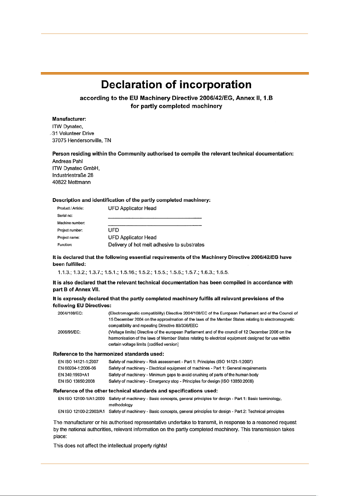
Chapter 1 Declaration of Incorporation
ITW Dynatec
Chapter 1
Declaration of Incorporation
UFD Applicator, Manual 40-43, Rev. 6.16 Page 7
Page 8

ITW Dynatec
Chapter 1
Declaration of Incorporation
Page 8 UFD Applicator, Manual 40-43, Rev. 6.16
Page 9

Chapter 2 Safety Instructions
ITW Dynatec
General Considerations
All operators and service personnel must read and understand this manual
before operating or servicing equipmen t.
All maintenance and service on this equipment must be performed by trained
technicians.
Read and adhere to the manual!
1. Read and follow these instructions.
Failure to do this could result in severe personal injury or death.
2. Keep the binding rules for accident prevention valid for your country and the place of
installation. Also keep the approved qualified technical rules for safety-conscious and
professional work.
3. Additional safety instructions and/ or symbols are located throughout this manual.
They serve to warn maintenance personnel and operators about potentially hazardous
situations.
4. Inspect the machine for unsafe conditions daily and replace all worn or defective parts.
5. Keep work area uncluttered and well lit. Remove all material or things not needed for
the production from the workspace of the equipment!
6. All covers and guards must be in place before operating this equipment.
7. Subject to technical modifications without notice!
8. To ensure proper operation of the equipment, use specified electrical and/ or air
supply sources.
9. Do not attempt to alter the design of the equipment unless written approval is received
from ITW Dynatec.
10. Keep all manuals readily accessible at all times and refer to it often for the best
performance from your equipment.
Warning Labels
Chapter 2
Safety Instructions
1. Read and obey all of the warning labels, signs and caution statements on the
equipment.
2. Do not remove or deface any of the warning labels, signs and caution statements on
the equipment.
3. Replace any warning labels, signs and caution statements which have been removed
or defaced. Replacements are available from ITW Dynatec.
UFD Applicator, Manual 40-43, Rev. 6.16 Page 9
Page 10

ITW Dynatec
Chapter 2
Safety Instructions
Safety Symbols in this Manual
1. WARNINGS and CAUTIONS are found throughout this manual.
WARNINGS mean that failure to observe the specific instructions may cause injury to
personnel.
2. CAUTIONS mean that failure to observe the specific instructions may damage the
equipment.
Safe Installation and O per at ion
Read and adhere to the manual!
1. Read this manual before applying electrical power to the equipment. Equipment may
be damaged by incorrect electrical connections.
2. To avoid possible failure of hoses, make sure all hoses are routed to avoid kinking,
tight radius turns (8” or less) and abrasive contact. Hot‐melt hoses should not have
prolonged contact with heat‐absorbing surfaces such as cold floors or metal troughs.
These heat‐absorbing surfaces can alter adhesive flow and cause incorrect
calibration. Hoses should never be covered with materials that prevent heat
dissipation, such as insulation or sheathing. Hoses should be spaced apart from each
other, not making direct contact.
3. Do not use adhesive that is dirty or that may be chemically contaminated. Doing so
can cause system clogging and pump damage.
4. When adhesive hand‐ held applicators or other movable applicators are used, never
point them at yourself or at any other person. Never leave a hand‐held applicator's
trigger unlocked when not actually in use.
5. Do not operate the hopper or other system components without adhesive for more
than 15 minutes if the temperature is 150 degrees C (300 degrees F) or more. To do
so will cause charring of the residual adhesive.
6. Never activate the heads, hand‐held applicators and/ or other application devices until
the adhesive's temperature is within the operating range. Severe damage could result
to internal parts and seals.
7. Never attempt to lift or move the unit when there is molten adhesive in the system.
8. In case of an emergency or exceptional incident, press the emergency stop button in
order to stop the unit quickly.
9. Use the unit only as it is intended to.
10. Never let the unit run unattended.
11. Operate the unit only in a faultless and fully functional condition. Check and make
sure that all safety devices work in proper form!
Page 10 UFD Applicator, Manual 40-43, Rev. 6.16
Page 11
Chapter 2
Safety Instructions
ITW Dynatec
DYNATEC'S WARRANTY.
Explosion/ Fire Hazard
1. Never operate this unit in an explosive environment.
2. Use cleaning compounds recommended by ITW Dynatec or your adhesive supplier
only.
3. Flash points of cleaning compounds vary according to their composition, so consult
with your supplier to determine the maximum heating temperatures and safety
precautions.
Use of PUR (Polyurethane) Adhesives
1. PUR adhesives emit fumes (MDI and TDI) that can be dangerous to anyone exposed
to them. These fumes cannot be detected by the sense of smell. ITW Dynatec strongly
recommends that a power‐vented exhaust hood or system be installed over any PUR
system.
2. Consult with your adhesive manufacturer for specifics about required ventilation.
CAUTION
Because of the nature of PUR adhesives to strongly bond in the presence of moisture,
care must be taken to prevent them from curing inside ITW Dynatec equipment.
If PUR adhesive solidifies in a unit, the unit must be replaced. Always purge old PUR
adhesive from the system per your adhesive manufacturer's instructions and time table.
ALLOWING PUR ADHESIVE TO CURE IN A UNIT OR ITS COMPONENTS VOIDS ITW
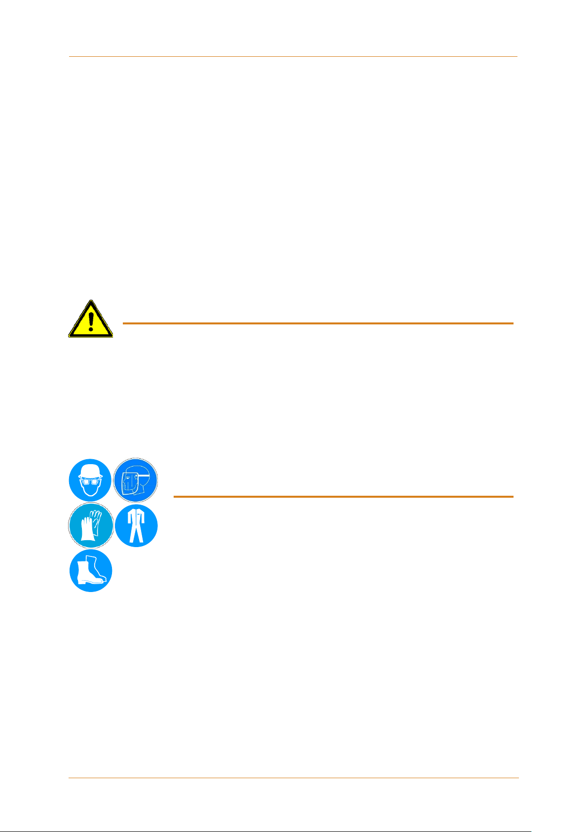
Eye Protection & Protective Clothing
WARNING
EYE PROTECTION & PROTECTIVE CLOTHING REQUIRED
1. It is very important that you PROTECT YOUR EYES when working around
hot melt adhesive equipment!
2. Wear a face shield conforming to ANSI Z87.1 or safety glasses with side
shields which conform to ANSI Z87.1 or EN166.
3. Failure to wear a face shield or safety glasses could result in severe eye injury.
4. It is important to protect yourself from potential burns when working around hot melt
adhesive equipment.
5. Wear heat-resistant protective gloves and long‐sleeved, protective clothing to prevent
burns that could result from contact with hot material or hot components.
6. Always wear steel‐reinforced safety shoes.
UFD Applicator, Manual 40-43, Rev. 6.16 Page 11
Page 12

ITW Dynatec
Chapter 2
Safety Instructions
WARNING HOT SURFACE
Electrical
DANGER HIGH VOLTAGE
1. Dangerous voltages exist at several points in this equipment. To avoid personal injury,
do not touch exposed connections and components while input power is on.
2. Disconnect, lockout and tag external electrical power before removing protective
panels.
3. A secure connection to a reliable earth ground is essential for safe operation.
4. An electrical disconnect switch with lockout capability must be provided in the line
ahead of the unit. Wiring used to supply electrical power should be installed by a
qualified electrician.
5. Notify the maintenance personnel immediately, if cables are damaged. Provide for
exchanging the defective components immediately.
Lockout/ Tagout
Switch the unit voltage-free before working!
Main switch OFF!
1. Follow OSHA 1910.147 (Lockout/ Tagout Regulation) for equipment's lockout
procedures and other important lockout/tagout guidelines.
2. Be familiar with all lockout sources on the equipment.
3. Even after the equipment has been locked out, there may be stored energy in the
application system, particularly in the capacitors within the panel box. To ensure that
all stored energy is relieved, wait at least one minute after removing power before
servicing electrical capacitors.
High Temperatures
1. Severe burns can occur if unprotected skin comes in contact with molten adhesive or
hot application system parts.
2. Face shields (preferred) or safety glasses (for minimum protection), heat-resistant
protective gloves and long-sleeved clothing m us t be worn whene ver wor k ing with or
around adhesive application systems.
Page 12 UFD Applicator, Manual 40-43, Rev. 6.16
Page 13
Chapter 2
Safety Instructions
ITW Dynatec
WARNING HIGH PRESSURE PRESENT
WARNING
High Pressure
1. To avoid personal injury, do not operate the equipment without all covers, panels and
safety guards properly installed.
2. To prevent serious injury from molten adhesive under pressure when servicing the
equipment, disengage the pumps and relieve the adhesive system's hydraulic
pressure (i.e. trigger the heads, hand‐held applicators, and/or other application
devices into a waste container) before opening any hydraulic fittings or connections.
3. IMPORTANT NOTE: Even when a system's pressure gauge reads “0” psi, residual
pressure and trapped air can remain within it causing hot adhesive and pressure to
escape without warning when a filter cap or a hose or hydraulic connection is
loosened or removed. For this reason, always wear eye protection and protective
clothing.
4. Either of the two High Pressure symbols shown may be used on ITW Dynatec
equipment.
5. Keep the given operating pressure.
6. Notify the maintenance personnel immediately, if hoses or components are damaged.
Provide for exchanging the defective components immediately.
Protective Covers
DO NOT OPERATE WITHOUT GUARDS IN PL ACE
1. Keep all guards in place!
2. To avoid personal injury, do not operate the application system without all covers,
panels and safety guards properly installed.
3. Never get your extremities and/or objects into the danger area of the unit. Keep your
hands away from running parts of the unit (pumps, motors, rolls or others).
UFD Applicator, Manual 40-43, Rev. 6.16 Page 13
Page 14

ITW Dynatec
Chapter 2
Safety Instructions
Servicing, maintenance
1. Only trained an d qualified personnel are to operate and service this equipment.
2. Before any service work disconnect the external power supply and the pressure air
supply!
3. Never service or clean equipment while it is in motion. Shut off the equipment and lock
out all input power at the source before attempting any maintenance.
4. Follow the maintenance and service instructions in the manual.
5. Keep the maintenance rates given in this documentation!
6. Any defects in the equipment that impact safe operation have to be repaired
immediately.
7. Check screws that have been loosened during the repair or maintenance, if they are
tight again.
8. Replace the air hoses in preventive maintenance regularly, even if they have got no
viewable damages! Adhere to the manufacturers` instructions!
9. Never clean control cabinets or other houses of electrical equipment with a jet of
water!
10. Adhere to the current safety data sheet of the manufacturer when using hazardous
materials (cleaning agents, etc.)!
Secure transport
1. Examine the entire unit immediately after receipt, if it has been delivered in perf ec t
condition.
2. Let damages in transit certify by the carrier and announce them immediately to ITW
Dynatec.
3. Use only lifting devices that are suitable for the weight and the dimensions of the
equipment (see drawing of the equipment).
4. The unit has to be transported upright and horizontally!
5. The unit has to cool down to room temperature before packaged and transported.
Page 14 UFD Applicator, Manual 40-43, Rev. 6.16
Page 15

Chapter 2
Safety Instructions
ITW Dynatec
EXTINGUISH FIRE
For safety reasons not appropriate extinguishing agents: None.
Treatment for Burns from Hot Melt Adhesives
Measures after being burned:
1. Burns caused by hot melt adhesive must be treated at a burn center. Provide the burn
center's staff a copy of the adhesive's M.S.D.S. to expedite treatment.
2. Cool burnt parts immediately!
3. Do not remove adhesive forcibly from the skin!
4. Care should be used when work ing with hot melt adhesives in the molten state.
Because they rapidly solidify, they present a unique hazard. Even when first solidified,
they are still hot and can cause severe burns.
5. When working near a hot melt application system, always wear safety shoes, heatresistant protective gloves, safety goggles and protective clothes that cover all
vulnerable parts of the body.
6. Always have first-aid information and supplies available.
7. Call a physician and/or an emergency medical technician immediately. Let the burns
medicate by a medic immediately.
Measures in case of fire
UFD Applicator, Manual 40-43, Rev. 6.16 Page 15
1. Please heed that not covered hot parts of the engine and molten hot melt may cause
heavy burns. Risk of burns!
2. Work very carefully with molten hot melt. Keep in mind, that already jelled hot melt can
be very hot, too.
3. When working near a hot melt application system, always wear safety shoes, heatresistant protective gloves, safety goggles and protective clothes that cover all
vulnerable parts of the body!
Measures in case of fire:
Wear safety shoes, heat-resistant protective gloves, safety goggles and protective
clothes that cover all vulnerable parts of the body.
Firefighting - burning hot melt:
Please keep attention to the safety data sheet given by the adhesive manufacturer.
Appropriate extinguishing agents:
Foam extinguisher, Dry powder, Spray, Carbon dioxide (CO2), Dry sand.
Firefighting - burning electrical equipment:
Appropriate extinguishing agents:
Carbon dioxide (CO2), Dry powder.
Page 16

ITW Dynatec
Chapter 2
Safety Instructions
1. When working on or with the unit, the legal obligations for waste avoidance and the
Keep attention to environmental protection standards
duly recycling / disposals have to be fulfilled.
2. Keep attention, that during installations, repairs or maintenance matters hazardous
to water, like adhesive / adhesive scrap, lubricating grease or oil, hydraulic oil,
coolant and cleaner containing solvent not pollute the ground or get into the
canalization!
3. These matters have to be caught, kept, transported and disposed in appropriate
reservoirs!
4. Dispose these matters according to the international, national and regional
regulations.
Page 16 UFD Applicator, Manual 40-43, Rev. 6.16
Page 17
Chapter 3 Description and Technical Specs
ITW Dynatec
If the unit is not used in accordance with this regulation, a safe operation cannot be
resulting from unintended use!
Intended use includes, that you
• do all maintenance within the given maintenance rates.
• Risk of burns from hot material.
• The safety valves may malfunction due to hardened or charred material.
Chapter 3
Description and Technical Specs
3.1 Applicable Safety Regulations
Intended Use
The UFD Applicator may be used only to apply suitable materials, e.g. adhesives. When
in doubt, seek permission from ITW Dynatec.
guaranteed.
The operator - and not ITW D ynatec - is liable for all personal injury or property damages
• read this documentation,
• heed all given warnings and safety instructions, and
Any other use is considered to be unintended.
Unintended Use, Examples
The UFD Applicator may not be used under the following conditions:
• In defective condition.
• In a potentially explosive atmosphere.
• With unsuitable operating/processing materials.
• When the values stated under Specifications are not complied with.
The UFD Applicator may not be used to process the following materials:
• Toxic, explosive and easily flammable materials.
• Erosive and corrosive materials.
• Food products.
Residual Risks
In the design of the UFD Applicator, every measure was taken to protect personnel from
potential danger. However, some residual risks cannot be avoided.
Personnel should be aware of the following:
• Risk of burns from hot Applicator components.
• Risk of burns when conducting maintenance and repair work for which the system
must be heated up.
• Risk of burns when attaching and removing heated hoses.
• Material fumes can be hazardous. Avoid inhalation. If necessary, exhaust material
vapors and/or provide sufficient ventilation of the location of the system.
• Risk of pinching parts of the body at running parts of the unit (pumps, motors, rolls or
others).
UFD Applicator, Manual 40-43, Rev. 6.16 Page 17
Page 18

ITW Dynatec
Chapter 3
Description and Technical Specs
Technical changes
Any kind of technical changes having impact to the security or the operational liability of
the system should only be done by written agreement of ITW Dynatec. Suchlike changes
made without given a corresponding written agreement will lead to immediate exclusion
of liability granted by ITW Dynatec for all direct and indirect subsequent damages.
Using foreign components
ITW Dynatec takes no responsibility for consequential damages caused by using foreign
components or controllers that have not been provided or installed by ITW Dynatec.
ITW Dynatec does not guarantee that foreign components or controllers used by the
operating company are compatible to the ITW Dynatec-system.
Setting-up operation
We recommend asking for an ITW Dynatec-service technician for the setting-up
operation, to ensure a functioning system. Let yourself and the people working with or
working on the system be introduced to the system on this occasion.
ITW Dynatec takes no responsibility for damages or faults caused by any untrained
personal.
Page 18 UFD Applicator, Manual 40-43, Rev. 6.16
Page 19

Chapter 3
Description and Technical Specs
ITW Dynatec
UFD Omega:
UFD Random:
3.2 Description of UFD Spray Applicator
Description
ITW Dynatec’s UFD Spray Applicators are air-operated, single or multi-module hot melt
adhesive applicator assemblies with integrated basket filters, which prevent particulate
matter from obstructing flow through the heads.
The Applicator is heated by replaceable cartridge heating elements which are controlled
by an integrated sensor and electronic control. Each model can be configured for ITW
Dynatec’s DynaControl, MCV or Upgrade control schemes or for Allen-Bradley PLC
controls. Pressure transducer ports are standard features for all Applicators. A choice of
adhesive inlets and an angled filter nut allows either vertical or horizontal spray.
Four standard UFD models supporting up to six modules, are available, ranging in width
from 50mm to 150mm (2” to 6”). Their design is metric.
Theory of Operation
Each Applicator features one or more modules (adhesive valve) mounted to a single
service block. Each module is opened and closed by air pressure (solenoid valve).
Springs are used to keep the stem closed when no air pressure is supplied to the head.
The rate of adhesive flow from the applicator is determined by the adhesive pressure
applied by the Adhesive Supply Unit’s (ASU’s) pump, the nozzle type and the stem stroke
adjustment.
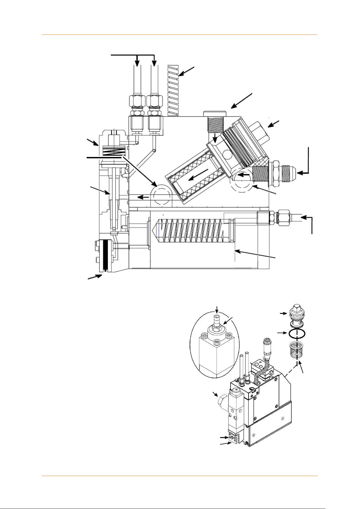
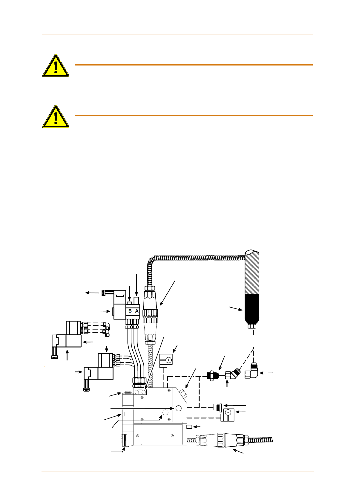
As shown in the illustration below, the heated adhesive supply hose may be connected at
the rear of the applicator or at the top. Adhesive flows from the hose into the service
block, through the filter and then to the module. Air pressure (Control Air) opens the
module, allowing adhesive to flow through the module’s nozzle.
Adapters are available to allow indus try-standard pressure transducers (1/2-20 thread) to
be connected to monitor adhesive pressure within the service block.
On the UFD spray models, an air preheater is located below the service block. The
preheater supplies heated air (Process Air), used to fiberize the adhesive streams, to the
UFD modules. The air preheater is thermally isolated from the service block and its
temperature is controlled independently.
The adhesive pressure in the system is influenced by the following parameters:
• Temperature and viscosity of the adhesive
• Size and speed of the Adhesive Application Unit’s (ASU’s) pump
• Cross-section and length of the adhesive hoses
• Adjusted adhesive pressure at Applicator (if adjustable pressure relief valve)
• Nozzle type
See illustration typical parts of UFD Applicator on next page.
Nozzles compatible with UFD Applicator:
Two different UFD nozzles (Omega and Random) are available to fiberize the
adhesive streams:
UFD Applicator, Manual 40-43, Rev. 6.16 Page 19
Page 20
ITW Dynatec
Chapter 3
Description and Technical Specs
Alternate Hose
Inlet
Process Air Inlet
Air Preheater
Piston
Accessory Port
UFD Module
Control Air Inlet
Electrical
Inlet
Mounting screw
Nozzle
Filter
O-ring
Filter Nut
Lock
Nut
Optional Drain
(Purge) Valve
Stroke Adjustment Screw
Connection
Alternate Glue
Fiberizing Nozzle
Filter Cap
Glue Inlet
Page 20 UFD Applicator, Manual 40-43, Rev. 6.16
Illustration: Standard UFD Spray Applicator
Basket
Page 21
Chapter 3
Description and Technical Specs
ITW Dynatec
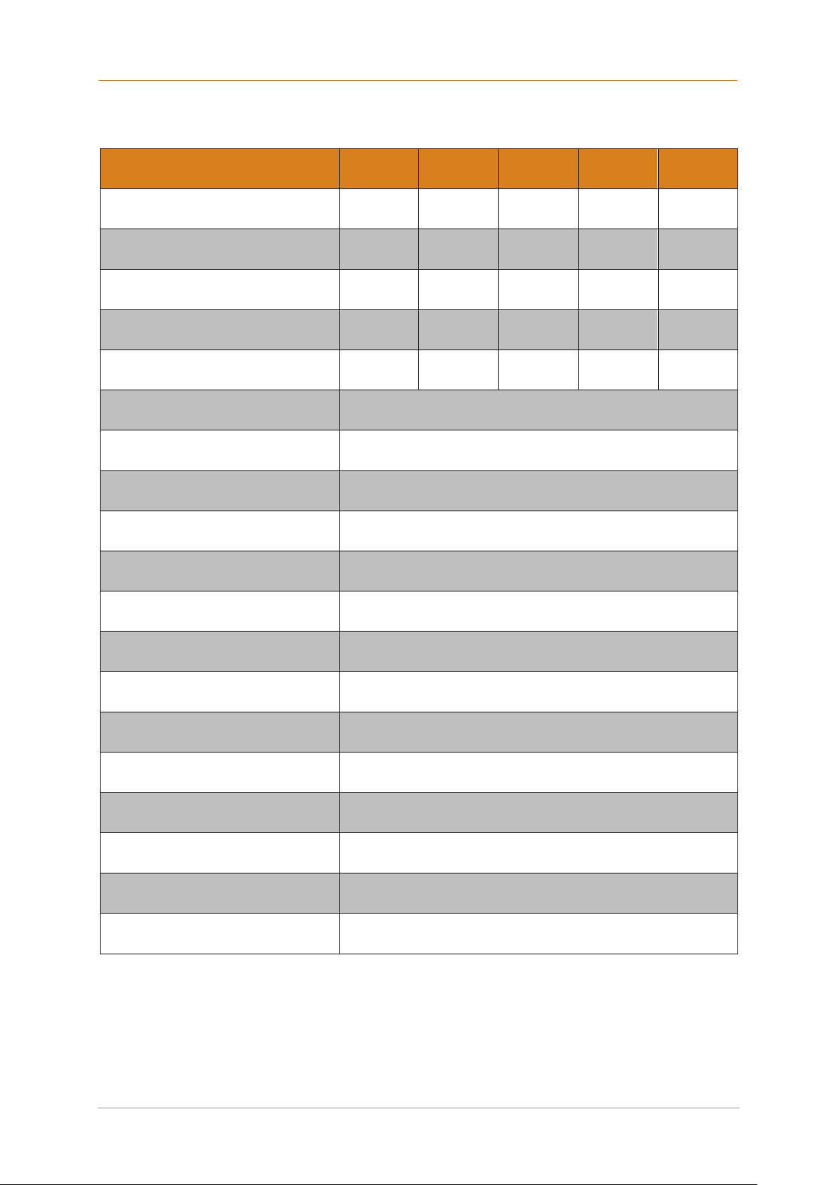
Technical Data
Model UFD 0501 0502 0753 1004 1506
Number of Modules
Spacing between nozzle centers
Wattage Adhesive Manifold
Wattage Standard Air Perheater
Wattage Slim Line Preheater
Supply voltage
Dimensions
Weight (including module and
solenoid valve)
Mounting
Temperature range
Warm-up time
1 2 3 4 6
- 25.2 mm 25.2 mm 25.2 mm 25.2 mm
450 450 525 600 900
600 600 900 1200 1200
400 400 600 800 1200
200-240 VAC/ 1p/ 50-60 Hz
See dimensional layout on follo wing pag e.
Model UFD0501: 3.52 kg (7.75 lb.)
M6 x 1 screws with insulators or 1/2” rod mount,
insulated clamps, 12 to 13 mm rod
38°C to 218°C (100°F to 425°F)
15 minutes for cold start/
5 minutes for module change only
Adhesive viscosity
Adhesive pressure range
Noise emission
Air pressure range
Air pressure range for high
speed snuffback modules (only)
Storage/ shipping temperature
Ambient service temperature
CE approval granted
100 to 30.000 mPa. sec. (100 to 30.000 centipoise)
68 bar maximum (1000 psi maximum)
70 dB(A)
4.1 to 6.9 bar (60 to 100 psi)
4.8 to 6.2 bar (70 to 90 psi)
-40°C to 70°C (-40°F to 158°F)
-7°C to 50°C (20°F to 122°F)
Yes
UFD Applicator, Manual 40-43, Rev. 6.16 Page 21
Page 22

ITW Dynatec
Chapter 3
Description and Technical Specs
Service Block Length:
150 6 = 150mm (6 port/ 1 solenoid)
Module Type:
No. of Modules installed:
Z (no modules)
Voltage:
Control:
Filter Options:
Number of Solenoids:
(not available for J, M)
Applicator Options:
A = Adds Purge Valve
Model Designation Guide
UFD XXX X X X X X X X X
Example: UFD 100 4 V 4 A 1 D 2 S
050 1 = (1 port/1 solenoid)
050 2 = 50mm (2 port/1 solenoid)
075 3 = 75mm (3 port/1 solenoid)
100 4 = 100mm (4 port/ 1 solenoid)
S = Standard (No Options)
2 = 240VAC
A = Vertic al Hi-Speed SB (manifold air)
H = Horizontal UFD* (continuous)
V = Vertical UFD* (continuous)
K = Horizontal UFD SB (intermittent)
F = Vertical UFD SB (intermittent)
J = Verti cal, Hi-Speed SB, (intermittent)
Festo
M = Horizontal, Hi-Speed SB, (intermittent)
Festo
P = Horizontal Hi-Speed SB (manifold air)
D = DynaControl / PLC
M = MCV
N = Upgrade, Nor (Nickel RTD)
L = Upgrade, Mel (J -type t herm ocouple)
P = Upgrade, Mel (Platinum RTD)
1, 2, 3, 4, 5 or 6
0 = Only for options J, M
E = Adds Balanced Solenoid Manifold
1, 2, 3, 4, 5, 6 or
A = 100 mesh, basket
B = 150 mesh, basket
C = 150 mesh, spin-on
D = 200 mesh, spin-on
Notes: When specifying an Applicator with no modules, (see “Z” above), the Module Type (H, V, etc.)
must still be specified for the application.
Page 22 UFD Applicator, Manual 40-43, Rev. 6.16
Page 23
Chapter 3
Description and Technical Specs
ITW Dynatec
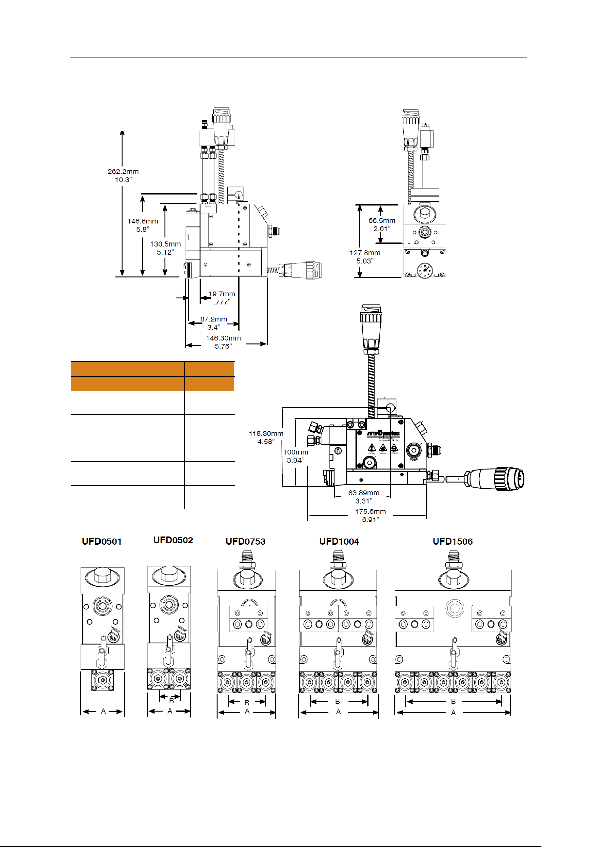
Dynafiber UFD Applicator,
side view:
Dynafiber UFD Applicator,
front view:
Dynafiber UFD
Width
Centers
Model No.
A
B
50mm
2“
50mm
2“
25.2mm
1“
75mm
3“
50.4mm
2“
100mm
4“
75.6mm
3“
150mm
6“
126mm
5“
Dimensions
UFD0501
UFD0502
UFD0753
UFD1004
UFD1506
SlimLine Applicator
-
UFD Applicator, Manual 40-43, Rev. 6.16 Page 23
Page 24

ITW Dynatec
Chapter 3
Description and Technical Specs
This page intentionally left blank.
Page 24 UFD Applicator, Manual 40-43, Rev. 6.16
Page 25
Chapter 4 Installation & Startup
ITW Dynatec
CAUTION
• Heed all safety instructions mentioned in Chapter 2.
• In any case the air has to be clean and dry! See advice in Chapter 4.3 “Quality of
applicator, 3/8” O.D. airline is recommended.
Advices:
occurs.
Chapter 4
Installation & Startup
• Before setting up, please read this documentation carefully.
• Pay attention to all the installation and connecting advices.
4.1 Conditions for set-up and mounting
Place requirement
Install the Applicator in the machine so that the operator is able to work on it from all
sides, for e.g. for adjusting, preparing, maintaining, repairing, cleaning, etc. See drawing
of the unit for admeasurements.
Mounting and alignment
• The complete unit has to be set up on solid, stable and flat ground.
• The alignment in height of the complete system has to be considered.
• The alignment of the machine has to be considered.
Electrical connection
• Necessary electrical connection has to be provided. See electrical schematics.
• Never connect or disconnect plug-and-socket connections under load!
• The service block’s incoming electrical power and temperature control is supplied
through the flexible cable exiting the adhesive supply hose cuff or through an
extension cable from the ASU. The Applicator has a circular, plastic connector which
mates with the connector attached to this cable.
• Incoming power and temperature control for the air preheater, if applicable, is supplied
by a cable extension from the ASU.
Pneumatic connection
compressed air”.
• Please heed that units with high air demand may not be used at the same time with
the same air supply.
• Incoming module-activation air is supplied through a solenoid valve. It must be clean
and unlubricated.
For conventional modules (module option H, V, HQ or VQ in the model number (see
previous pages), the module activation air is controlled by a four-way solenoid valve
and should be separately regulated and maintained at a pressure between 4.1 to 6.9
bar (60 to 100 psi). Air lines from the solenoid valve should be 6.4mm (1/4 inch).
Head air inlet ports are G 1/8 threads (1/8 NPT).
For snuffback modules (all other module options), the module activation air is
UFD Applicator, Manual 40-43, Rev. 6.16 Page 25
controlled by a either a four-way or a five-way solenoid valve. See Appendix A and B
for details on the solenoid setup.
• Incoming process (preheater) air must be supplied through a pressure regulator. The
air must be clean and unlubricated. Operating pressure depends on the choice of
nozzle. The Applicator’s air supply line must be at least 1/4” O.D. For the UFD 150
• Check all screw connections at the unit and retighten if necessary.
• Lay the cables and heated hoses so that no risk or least possible risk of stumbling
Page 26
ITW Dynatec
Chapter 4
Installation & Startup
CAUTION
valid regulations.
WARNING
• Risk of burns and risk of injury!
Air Inlet
Fitting
Muffler
To Timer or
Limit Switch
Purge Button
Solenoid
Mounting of
assemblies
Stroke Limit Adjustment
Alternate Hose Inlet
(one on each side)
Weep Hole
Nozzle
Accessory Port (for a drain
(one on each side)
Hose/ Head Electrical
Connection
Alternative
Control Air
Inlet Port
Rod Mount Bracket
Filter Nut
Adhesive Inlet
or
90° Hose Fitting
45° Hose Fitting
Rod Mount Bracket & Plug
position.
Process Air Inlet for Air Preheater
Electrical Connection
For Air Preheater
4.2 Installation & Startup
• All work on or with this unit is only permitted for sk illed personnel!
• Pay attention to the electrical schematics!
• Clean and dry air and air pressure of 6 bar to the applicator solenoids is required.
• All heating elements have to be mounted and operated secured and according to the
• While installing the Applicator, use an appropriate protection device to avoid
unintended contact with heated parts and with spilling out Hotmelt. The protection
device has to prevent also the operator against not reaching into the adhesive
application and against injuring.
Typical installation for an ULTRA Applicator:
1. Install the Applicator on the machine at the foreseen place.
The Applicator should be supported from brackets that permit lateral and vertical
adjustments. Mount the Applicator on a 12mm to 13mm rod or bracketry using the 6
mm screws and insulators provided. Allow access to the filter. Be sure that the stroke
limit adjustment screws are accessible and that the “weep” holes are visible for
periodic inspection. Leave s uff ic ient clearance to install a pressure transducer, if
applicable, and allow access to a drain valve, if installed.
Installation Diagram: See the diagram for location of the components referred to in the following
section.
optional
solenoid
valve and/ or transducer tap)
Page 26 UFD Applicator, Manual 40-43, Rev. 6.16
Adhesive Supply Hose
used in alternate glue inlet
Page 27

Chapter 4
Installation & Startup
ITW Dynatec
6 bar air pressure are required. Reason:
be installed between the standard air regulator/ filter and the UFD Applicator.
Heed the following for the installation of the heated hoses:
they cannot be repaired the hose would have to be changed completely.
2. Connect the compressed-air supply to Applicator. Connect all solenoids with air hoses
as required.
• Lower air pressure causes uneven adhesive application.
• The modules do not switch or switch with delay, resp. open and close again, if the air
supply is uneven.
• Only permanent pressure and sufficient volume flow leads to reproducible application
accuracy regarding position and amount.
CAUTION: Do not use lubricating oil with the air supply as Applicators are
lubricated at the factory and do not require lubrication when used in production.
Where oil is present in the air supply, a coalescing filter (Dynatec PN 100055) must
UFD Applicators require at least one solenoid valve for each applicator. If your head was
ordered without a solenoid valve, a 4-way valve (or a 5-way valve for snuffback modules)
should be mounted so that the air lines to each Applicator are as close to the same length
as practical.
Note: Air lines and fittings must be capable of withstanding temperatures up to 218°C
(425°F). ITW Dynatec supplies Air Control Filter Coalescing Kits (PN 100055) to be used
with air-operated Applicators (see the Air Control Filter Coalescing Kit Manual in
Appendix A of this manual).
For process (preheater) air control, the filter/ regulator kit PN 107404 is recommended. It
contains a 0-50 psi air filter/ regulator combination and a liquid-filled gauge for accurate
process air control.
See the Process (Preheater) Air Control Filter/ Regulator information in Appendix B.
When connecting the air lines to the applicator, the air line which has air pressure to the
module when the solenoid is OFF is the closing air line. See Appendix A and B for details
and diagrams of solenoid setup.
3. If a pre- or post- filter pressure transducer is to be utilized: install the supplied adapter
into the desired accessory port. Thread the transducer into the adapter (transducer
adapter has 1/2-20 thread). Follow the transducer manufacturer’s recommendations
for torque specifications. Note: the alternate hose inlets on either side of the Applicator
can also be used for the transducer adapter.
4. Before making the adhesive connection to the Applicator, align the adhesive supply
hose with its electrical connector oriented in relation to the electrical connector on the
top of the Applicator.
Connect the swivel fitting of the hot melt hose to the adapter on the service block,
using either the inlet port located below the filter nut or the port located on the top of
the Applicator (beside the electrical connection in the diagram). When tightening the
hose fitting, hold the hose cuff to prevent the hose core from rotating.
• Heated hoses may be damaged by overheating, if they are laid faulty.
• The heated hoses may not be stacked one on the other!
• The heated hoses may not be pressed together and / or bound.
• Put the hoses separated next to each other!
• The connections for supply resp. return hoses may not be mixed up.
• It is essential that the hoses will be laid without twisting!
• Heated hoses may not be fastened with binders or similar.
• Heated hoses may not be laid on a sharp edge.
• When using a balancer, a hose support with a radius of 400mm has to be mounted.
Reason: The sensor cables and heating cables within the hoses can be damaged. As
UFD Applicator, Manual 40-43, Rev. 6.16 Page 27
Page 28

ITW Dynatec
Chapter 4
Installation & Startup
WARNING! HIGH PRESSURE! HOT ADHESIVE!
Use a stable, deep container to collect hot-melt adhesive and/ or oil.
Purge the Applicator before every start of production respectively of a shift by allowing
Bring the Applicator in work position and continue production.
5. Make the electrical connection from the hose to the applicator by connecting the
6. Connect the spray air line to the preheater using the adapter provided. Do not
7. Make the electrical connection from the extension cable to the preheater by
8. It is advisable to check the temperature of the applicator. This can be done through
9. Purge the Applicator of air and oil. Turn the Applicator O N electric a l ly and
10. Replace the nozzle, orienting the nozzle tip so it points toward the substrate.
11. Interconnect the components with the foreseen Profibus (or EtherNet, etc.) interface
Daily operation
female connector of the hose to the male connector of the applicator.
overtighten the compression fitting, or the air line could collapse, reducing air flow.
connecting the female connector of the cable to the male connector of the preheater
the temperature readout of the adhesive supply unit. Surface temperature may be
checked with a separate pyrometer and surface probe or with a dial thermometer.
Turn the system power switch ON. Permit the applicator to warm up at least 15
minutes (5 minutes for module change) before reading temper ature.
pneumatically.
During the purging procedure, hot adhe sive and oil can come out of
the Applicator under high pressure. Wear safety glasses, gloves and
protective clothing.
Remove the nozzle from the module. Place a heat resistant container under the
module to collect the material that drains from the Applicator. Manually open the
solenoid by pushing (with a small screwdriver or other tool) the purge button located
on the solenoid coil. Continue to hold in the purge button until all air and oil have
drained and only adhesive flows from the module.
cables (if applicable).
the adhesive flows out until it is satisfactory.
Then switch off the adhesive and clean the nozzle from adhesive.
Page 28 UFD Applicator, Manual 40-43, Rev. 6.16
Page 29

Chapter 4
Installation & Startup
ITW Dynatec
WARNING! HOT SURFACE & ADHESIVE!
Special Installation Notes on HiSpeed, Vertical Snuffback, Direct-Air Module
Special Installation Notes on Optional PN 112690, 112440 & 112934 HiSpeed, Vertical
Snuffback, Direct-Air Module (Option Code C,D, G see Chapter Model Designation Guide)
The PN 112690, 112440 & 112934 modules are designed for the solenoid valve to be
connected directly to the module air cylinder. Fittings and tubing are included with the
module assembly.
If alternative fittings or tubing are desired, the recommended tubing is aluminum or
stainless steel, 1/4” OD x 3/16” ID. For best performance, the tubing length should be as
short as practical (recommended length is 2.5” min. to 6” max.). The port threads in the
module are 1/8-27 NPT.
If necessary for clearance, the air cylinder can be rotated to re-position the tube fittings.
Remove the four cap screws securing the air cylinder, and without removing the air
cylinder, rotate to the desired position. Replace the cap screws and torque crosswise,
first to 5 in-lb., then to 20 in-lbs.
Recommended operating air pressure is 70-90 psi.
Operation of Optional Drain Valve
(Option Code A, see Chapter Model Designation Guide)
UFD Applicators with the “A” option are equipped with a drain valve located on the right
side of the Applicator. This drain valve allows residual adhesive pressure to be relieved
prior to maintenance or repair of the Ap pl icator . Dur ing Applicator installation, the drain
valve can be relocated to the left side of the Applicator for access, if necessary.
The drain valve consists of a valve body with a rotatable outlet collar that directs the flow
of adhesive. A plug is located inside the body, retained by a snap ring to prevent the plug
from being fully removed.
Operation
1. Ensure that all pumps in the ASU (Adhesive Supply Unit) are turned off. Power down
the ASU or disable the Applicator and preheater zones at the control panel.
Disconnect all electrical cables from the Applicator.
The equipmet will still be hot when this procedure is being done.
Use insulated gloves and protective c lothing.
2. Place a suitable container under the Applicator to catch adhesive. Using pliers, rotate
the knurled outlet collar of the drain valve so that the exit hole points toward the
container, and away from any personnel. Stand away from the valve while the
adhesive pressure is being relieved.
3. Using a 19mm (3/4”) wrench on the valve body to prevent rotation, insert a 5mm hex
wrench into the plug. Rotate the plug counter-clockwise to allow adhesive to flow
through the valve.
4. If no adhesive flows from the drain valve, do not assume that there is no adhesive
pressure in the system. Always verify that adhesive pressure has been completely
relieved before proceeding with maintenance or repairs. Never remove the snap ring
in the end of the valve, as this would allow the plug to be removed, possibly resulting
in personal injury.
5. After maintenance or repairs are complete, tighten the plug securely. Wipe any
adhesive from the outer surface of the drain valve.
UFD Applicator, Manual 40-43, Rev. 6.16 Page 29
Page 30
ITW Dynatec
Chapter 4
Installation & Startup
WARNING! HOT SURFACE & ADHESIVE!
max. oil
(mg/m3)
1
0,1
0,1
-70
0,01 2 1 1 -40
0,1
3
5 5 -20
1 4 15
8
+3
5
5
40
10
+7
25 6 +10
7 not defined
Purging Adhesive Through the Applicator
This procedure may be used anytime the operator wishes to purge old adhesive from the
Applicator and replace it with fresh adhesive. For example, this procedure could be used
in instances where the adhesive system has been held at temperature for an extended
time without running, such as during a produc tio n line s tar t-up.
The equipment will still be hot when this procedure is being do ne.
Use insulated gloves and protective c lothing.
Procedure
1. Remove all nozzles. Place a suitable container under the Applicator to catch adhesive.
2. Activate the modules and manually run the adhesive pump to purge the hoses and
Applicators of old adhesive. Purge until the adhesive exiting the modules is fresh.
3. Check system pressure to see if filters are clogged and need to be changed.
4. Replace the nozzles and check the adhesive flow through them. Compare to target
flow.
5. Check the nozzle spray pattern.
6. Clean any nozzles that do not spray properly and check the spray pattern again.
4.3 Quality of compressed Air
Compressed air quality class according to ISO 8573-1
• We recommend to use a maintenance-unit for compressed-air conditioning with a filter
40µm.
• Keep the quality class 5.4.2 according to ISO 8573-1.
Classification of Quality Classes According to ISO 8573-1:
Class 1. Particulate Material 2. Water Content 3. Oil Content
max. particle size
(μm)
max. particle density
Page 30 UFD Applicator, Manual 40-43, Rev. 6.16
(mg/m3)
max. pressure dew point
(°C)
concentration
Page 31

Chapter 5 Maintenance and Repair Notes
ITW Dynatec
Heed all security advices given in Chapter 2.
3. Open the pressure purge valve manually until the pressure is relieved.
Maintenance and Repair Notes
5.1 Security advices for maintenance and repair
Use only original parts from ITW Dynatec, otherwise ITW Dynatec’s
warranty is void!
Maintenance and repair work is only permitted for skilled personnel!
Always wear safety shoes, heat-resistant protective gloves, safety goggles
and protective clothing that cover all vuln er ab le parts of the bod y while
working on the heated unit! Risk of injury or heavy burns!
High Voltage! Risk of injury and mortal danger!
• All electrical connections must be made by qualified electrical personnel.
• Care must be taken to assure proper grounding prior to any disassembly.
• Lockout and tag the electrical sources as required.
• Make sure there is no electrical power on the leads you will be
connecting.
• When covers are removed, high voltage sources create an electrocution
hazard.
• Wear appropriate safet y equipm ent when wor k ing with high vol tag e
sources.
Parts and surfaces of the unit get very hot. High temperatures! Risk of
heavy burns!
High adhesive temperature and adhesive pressure! Risk of injury or
heavy burns!
Always assume that the system is under pressure, proceed with caution.
Keep a cool-pack, or bucket of clean water near the work area.
Place a heat-resistant catchment container/underlay under the components.
Hot adhesive may come out.
CAUTION: At working temperature, molten adhesive could cause heavy
burns. Let spilled out adhesive cool down first, before removing it!
CAUTION: Use only lint-free cleaning cloth and suitable cleaner for cleaning!
Do not damage surfaces! Do not scratch above them with sharp-edged
tools, otherwise the components will get leaky and inoperable!
All maintenance and repair work has to be done at working
temperature, except as noted otherwise. Else there is a risk of
damaging the unit components!
Before any service work disconnect the external power supply and
switch the unit voltage-free:
1. Switch off the main switch and the controller.
2. Disconnect the power supply respectively remove the plug / cable.
3. Guard the unit against unauthorized restarting!
Before any service work the adhesive pressure must be relieved
throughout the system. Switch the unit pressureless:
1. Disconnect the pressure air supply.
2. Turn the pressure regulator to zero bar, if necessary. Wait approximately
1 minute until the pressure is relieved.
Chapter 5
UFD Applicator, Manual 40-43, Rev. 6.16 Page 31
Page 32

ITW Dynatec
Chapter 5
Maintenance and Repair Notes
CAUTION
temperature.
CAUTION
Applicator.
5.2 Re-Assembly Procedures and General Cautions
Unless noted, component re-assembly is simply the reverse sequence of the disassembly
procedures. However, the following “cautions” should be followed (whenever they apply)
for proper re-assembly:
In general, all O-RINGS AND SEALS must be replaced whenever hot-melt equipment is
re-assembled. All new O-rings must be lubricated with O-ring lube (PN N07588).
TAPERED PIPE THREADS are found on air pipe fittings used with the pump air supply
and on the outlet filter manifold. Apply thread sealant (PN N02892) whenever tapered
pipe threaded parts are re-assembled.
SOME FITTINGS used for adhesive on hot melt equipment have straight threads and Oring seals. Use of thread sealant is not necessary with these parts, but the O-ring seals
should be clean and lubricated. Tighten straight-threaded parts and fittings until their
shoulders are firmly seated. Excessive torque may damage straight-threaded parts and
the use of power wrenches is not recommended.
HOT-MELT RESIDUE must be cleaned from parts before they are re-assembled,
particularly from threaded parts. As a precaution against adhesive residue preventing
proper re-assembly, threaded parts must always be re-tightened at operating
5.3 Stroke Limit Adjustment
All conventional MR1300 applicators are equipped with a stroke limit adjustment.
For snuffback valves, the stroke is factory pre-set and no field adjustment is necessary.
Whenever the conventional module is disassembled, the stroke limit must be adjusted
using the following procedure:
1. Bring applicator up to operating temperature.
2. Loosen the lock nut (see illustration on next pages, under Chapter 5.5 Replacement of
the Built-in Filter) located on the top of the module.
3. Bottom the stroke adjustment screw lightly.
Tightening the stroke adjustment to shut OFF the nozzl e will cause damage to the
4. Back off the screw one-half to one turn.
5. While holding the screw in position, tighten the lock nut.
Page 32 UFD Applicator, Manual 40-43, Rev. 6.16
Page 33

Chapter 5
Maintenance and Repair Notes
ITW Dynatec
WARNING
Maintenance and repair work is only permitted for skilled personnel!
protective clothing.
5.4 Relieving Adhesive Pressure
Heed all security advices given in Chapter 5.1.
Always wear safety shoes, heat-resistant protective gloves, safety goggles
and protective clothing that cover all vulnerable parts of the body while
working on the heated unit! Risk of injury or severe burns!
Components and adhesive are hot. Take every precaution to prevent the
material and hot surfaces from contacting the skin.
During the purging procedure, hot adhe sive can come out of the
Applicator under high pressure. Wear safety glasses, gloves and
Many maintenance and troubleshooting procedures potentially expose the maintenance
technician to dangerous hot adhesive, which is under pressure. Follow this procedure to
release the adhesive pressure in the Applicator before performing such maintenance.
1. The Applicator should be at operating temperature.
2. Turn the ASU’s pump/ motor OFF.
3. Place a heat-resistant catchment container/underlay under the Applicator.
Relieving Adhesive Pressure Manually:
1. Push the purge button located on the side of the air solenoid coil.
Or, if the ASU filter block is equipped with a drain, adhesive pressure may be relieved
at the ASU.
Relieving Adhesive Pressure by using the Optional Drain Valve (if applicable):
1. Place a heat-resistant container under the drain valve. If necessary, rotate the drain
valve’s opening by turning its knurled collar so that the opening is aiming downward
into the container.
2. With a 5mm hex key screwdriver (Allen-wrench), slowly loosen the drain valve’s purge
screw (do not try to remove it) and allow the adhesive and residues to flow out of
Applicator. Be sure to stand clear since there may be residual adhesive pressure in
the Applicator.
3. Turn ON the ASU’s pump/ motor. When all the contaminants have run out and the
adhesive is clean, retighten the screw.
UFD Applicator, Manual 40-43, Rev. 6.16 Page 33
Page 34

ITW Dynatec
Chapter 5
Maintenance and Repair Notes
WARNING
Maintenance and repair work is only permitted for skilled personnel!
protective clothing.
1. Stop all motors.
care not to cut the O-ring.
Mounting screw
Filter
Basket
O-ring
Filter Nut
Lock Nut
Stroke Adjustment Screw
Optional Drain
(Purge) Valve
5.5 Replacement of the Built-in Filter
Heed all security advices given in Chapter 5.1.
Always wear safety shoes, heat-resistant protective gloves, safety goggles
and protective clothing that cover all vulnerable parts of the body while
working on the heated unit! Risk of injury or severe burns!
Components and adhesive are hot. Take every precaution to prevent the
material and hot surfaces from contacting the skin.
During the purging procedure, hot adhe sive can come out of the
Applicator under high pressure. Wear safety glasses, gloves and
Refer to the drawing in Chapter 7 for more information.
The applicator must be at operating temperature.
Procedure for Basket-type Filter (Filter Codes A & B):
2. Switch the unit voltage-free and
pressureless.
3. Guard the unit against
unauthorized restarting.
4. Place a heat-resistant catchment
container/underlay under the
Applicator. Hot adhesive may
come out!
5. Relieve the adhesive pressure by
following the instructions under
Chapter 5.4 “Relieving Ad h esiv e
Pressure”.
6. Unscrew and remove the filter
nut.
7. With needle nose pliers, pull the
filter basket out of the manifold.
8. Replace the O-ring on the filter
nut. Apply O-ring lubricant (PN
N07588) to the new O-ring.
9. Apply a coat of anti-seize to the
threads of the filter nut.
10. Re-install the filter basket and
the filter nut. Tighten the filter
nut until it is seated firmly, taking
Nozzle
Page 34 UFD Applicator, Manual 40-43, Rev. 6.16
Page 35

Chapter 5
Maintenance and Repair Notes
ITW Dynatec
1. Stop all motors.
O-ring
Filter Cap
O-ring groove
Sealing washer
Spin-on Filter
Procedure for Spin-on Filter (Filter Code C)
2. Switch the unit voltage-free and
pressureless.
3. Guard the unit against unauthorized
restarting.
4. Place a heat-resistant catchment
container/underlay under the Applicator. Hot
adhesive may come out!
5. Relieve the adhesive pressure by following
the instructions under Chapter 5.4 “Relieving
Adhesive Pressure”.
6. Unscrew and remove the filter cap.
7. Unscrew the filter from the filter cap.
8. Remove and discard the old sealing washer
and O-ring.
9. Make sure the mating surface of the filter cap
is clean.
10. Install a new sealing washer, filter and O-
ring. Torque the filter to 40-50 in-lbs
(4.5 – 5.5 Nm) on the cap.
11. Apply a coat of anti-seize to the threads of
the filter cap.
12. Re-install the filter and the filter cap. Tighten
the filter cap until it is seated firmly, taking
care not to
13. Close the pressure bleed (purge) valve,
return the equipment to service and check
for leaks.
14. If leaking, it might be necessary to replace
the filter cap’s O-ring.
cut the O-ring.
(upper groove)
UFD Applicator, Manual 40-43, Rev. 6.16 Page 35
After finishing the maintenance or repair works:
Remove all materials and tools used during the repair or maintenance from the
workspace of the unit.
Connect the voltage supply and the compressed air supply. Heat the unit up. Wait until
all temperatures are within the tolerances and the adhesive in the tank is molten
completely.
Continue production.
Page 36

ITW Dynatec
Chapter 5
Maintenance and Repair Notes
WARNING
Maintenance and repair work is only permitted for skilled personnel!
protective clothing.
1. Stop all motors.
2.8 Nm).
Module’s two
5.6 Replacement of the Module
Modules Which Are Not Serviceable
The following modules cannot be customer-serviced:
• PN 112440 Module, High-Speed SB, Hor, Dir Air
• PN 112444 Module, High-Speed SB, Hor, Bck Air
Replacement of the Standard Module
Heed all security advices given in Chapter 5.1.
Always wear safety shoes, heat-resistant protective gloves, safety goggles
and protective clothing that cover all vuln er ab le parts of the bod y while
working on the heated unit! Risk of injury or severe burns!
Components and adhesive are hot. Take every precaution to prevent the
material and hot surfaces from contacting the skin.
During the purging procedure, hot adhe sive can come out of the
Applicator under high pressure. Wear safety glasses, gloves and
Refer to the drawing in Chapter 7 for more information.
2. Switch the unit to stand-by and pressureless.
3. Place a heat-resistant catchment
container/underlay under the Applicator. Hot
adhesive may come out!
4. Relieve the adhesive pressure by following the
instructions under Ch apt er 5.4 “Relieving Adhesive
Pressure”.
5. Remove the module from the service block by
removing the two mounting screws on the front of
the module with a hex key screwdriver (Allen
wrench). Make sure that the old O-rings located on
the back of the module are also removed (the new
module will include new O-rings).
6. Mount the new module in reverse order and att ach
it to the manifold with a torque of 20-25 in./lbs (2.3-
After finishing the maintenance or repair works:
Remove all materials and tools used during the repair or maintenance from the
workspace of the unit.
Connect the voltage supply and the compressed air supply. Heat the unit up. Wait until
all temperatures are within the tolerances and the adhesive in the tank is molten
completely.
Continue production.
Page 36 UFD Applicator, Manual 40-43, Rev. 6.16
mounting screws
Page 37

Chapter 5
Maintenance and Repair Notes
ITW Dynatec
CAUTION
premature seal breakdown and leakage of glue from the Applicator!
Module Assembly Instructions for the PN 104993 UFD Module
Demount the module from the service block, refer to the instructions in Chapter 5.6
Replacement of Standard Module on previous page.
Use the component illustration and parts list in Chapter 7 as a reference with the
following instructions for the PN 104993 UFD module.
ITW Dynatec has a Module Seal Kit available (PN 105150) which contains the
components necessary to rebuild one module, including the seal cartridge assembly, all
O-rings, spring and seal lubricant.
1. During re-assembly, coat all O-rings with a liberal amount of High Temp Lube (PN
N07588).
DO NOT SUBSTITUTE! Failure to use High Temp Lube (N07588) may result in
2. Insert the new seal cartridge assembly into the module body. (Note that there are two
holes in the seal cartridge cavity in the module body. One hole accepts the roll pin in
the seal cartridge. The other is an air hole which must line up with the air hole in the
seal cartridge.) Align the roll pin in the seal cartridge with the corresponding hole in the
top of the module body. Press the seal cartridge into position. The air hole in the seal
cartridge must align with the air ho le in the module body for the valve to
function properly.
3. Place a new piston O-ring onto the stem assembly and slowly insert the stem
assembly into the seal cartridge.
4. Place the new spring on top of the piston.
5. Loosen and back out the adjusting screw in the air cylinder. Place the air cylinder over
the spring and piston and press down into place. Take care not to dislodge the spring
or damage may result. Secure the air cylinder with the four mounting screws.
6. Place new O-rings on the seat assembly and insert the seat assembly into the bottom
of the module body. Secure with the four mounting screws. Spring resistance will be
felt as the screws are tightened. Tighten the screws evenly to avoid binding.
7. Place new O-rings into the grooves on the rear face of the module and mount the
module onto the service block.
8. Allow five minutes for the module to heat. Adjust the stem stroke to the desired
setting.
To disassemble, reverse above order.
UFD Applicator, Manual 40-43, Rev. 6.16 Page 37
Page 38

ITW Dynatec
Chapter 5
Maintenance and Repair Notes
CAUTION
premature seal breakdown and leakage of glue from the Applicator!
Module Assembly Instructions for the PN 106224 UFD or 106226 HiTemp UFD Module
Demount the module from the service block, refer to the instructions in Chapter 5.6
Replacement of Standard Module on previous pages.
Use the component illustration and parts list in Chapter 7 as a reference with the
following instructions for the PN 106224 or 106226 module. ITW Dynatec has a Module
Seal Kit available (PN 105150/ 803012 for Hi Temp) which contains the components
necessary to rebuild one module, including the seal cartridge assembly, all O-rings,
spring and seal lubricant.
1. During re-assembly, coat all O-rings with a liberal amount of High Temp Lube (PN
N07588).
DO NOT SUBSTITUTE! Failure to use High Temp Lube (N07588) may result in
2. Insert the new seal cartridge assembly into the module body. (Note that there are two
holes in the seal cartridge cavity in the module body. One hole accepts the roll pin in
the seal cartridge. The other is an air hole which must line up with the air hole in the
seal cartridge.) Align the roll pin in the seal cartridge with the corresponding hole in the
top of the module body. Press the seal cartridge into position. The air hole in the seal
cartridge must align with the air ho le in the module body for the valve to
function properly.
3. Place a new piston O-ring onto the stem assembly and slowly insert the stem
assembly into the seal cartridge.
4. Place the new spring on top of the piston.
5. Loosen and back out the adjusting screw in the air cylinder. Place the air cylinder over
the spring and piston and press down into place. Take care not to dislodge the spring
or damage may result. Secure the air cylinder with the four mounting screws.
6. a. Follow this step for new-style modules (those built after 11/12/07): Place new O-
rings on the vertical adapter and insert the seat assembly into the bottom of the
module body. Spring resistance will be felt as the screws are tightened. Tighten the
screws evenly to avoid binding.
b. Follow this step for old-style modules (those built prior to 11/12/07): Place new Orings on the seat assembly and insert the seat assembly into the bottom of the module
body. Place new o-rings on the vertical adapter. Place the brass seal and the vertical
adapter onto the seat assembly and secure with the four mounting screws. Spring
resistance will be felt as the screws are tightened. Tighten the screws evenly to avoid
binding.
7. Place new O-rings into the grooves on the rear face of the module and mount the
module onto the service block.
8. Allow five minutes for the module to heat. Adjust the stem stroke to the desired
setting.
To disassemble, reverse above order.
Page 38 UFD Applicator, Manual 40-43, Rev. 6.16
Page 39

Chapter 5
Maintenance and Repair Notes
ITW Dynatec
CAUTION
premature seal breakdown and leakage of glue from the Applicator!
O-rings
Piston
PN 110840
UFD Module
UFD SB (Snuff-Back) Valve Cartridge
PN 111074
Vertical SB UFD M odule
Module Assembly Instructions for the PN 110840 Horizontal SB and PN 111074 Vertical SB UFD Modules
Demount the module from the service block, refer to the instructions in Chapter 5.6
Replacement of Standard Module on previous pages.
Use the component illustrations and parts lists in Chapter 7 as a reference with the
following instructions for the PN 110840 & 111074 SB UFD modules. ITW Dynatec has a
Module Rebuild Kit available (PN 110889) which contains the components necessary to
rebuild one module, including the valve cartridge assembly and O-rings.
Lip seals
Horizontal SB
1. Disassemble the UFD SB module. Discard the old valve cartridge and thoroughly
clean the remaining parts.
2. Lightly coat the O-rings on the new valve cartridge (included in the kit and shown
above) with a high-temperature lubricant, such as PN 001U002 Dow 112 or PN
001V078 Krytox GPL206.
Note: Take care to keep lubricant off of the air piston lip seals.
DO NOT SUBSTITUTE! Failure to use High Temp Lube (N07588) may result in
3. Carefully install the new valve cartridge into the SB module body, pushing it in until it
is firmly seated.
4. Making sure that the air cylinder and piston lip seals are clean and dry, carefully install
the air cylinder over the piston and onto the valve cartridge.
5. Align the air cylinder’s external O-ring with the three ex ter nal O-rings in the SB
module’s body.
6. Secure the air cylinder with the four M3 x 35mm long cap screws dis-assembled in
step 1.
7. Torque the cap screws cross-wise to 20 inch-lb. (2.3 NM).
8. Install new external o-rings (included in kit) on the SB module with a minimal coating
of high-temp lubricant.
The module is now ready for installation and service.
To disassemble, reverse above order.
UFD Applicator, Manual 40-43, Rev. 6.16 Page 39
Page 40

ITW Dynatec
Chapter 5
Maintenance and Repair Notes
WARNING
Maintenance and repair work is only permitted for skilled personnel!
protective clothing.
1. Stop all motors.
UFD High-Speed
UFD Snuffback
5.7 Replacement of the UFD Nozzle
Heed all security advices given in Chapter 5.1.
Always wear safety shoes, heat-resistant protective gloves, safety goggles
and protective clothing that cover all vuln er ab le parts of the bod y while
working on the heated unit! Risk of injury or severe burns!
Components and adhesive are hot. Take every precaution to prevent the
material and hot surfaces from contacting the skin.
During the purging procedure, hot adhe sive can come out of the
Applicator under high pressure. Wear safety glasses, gloves and
Refer to the drawing in Chapter 7 for more information.
Occasionally nozzles can become clogged with char, residue or other foreign material.
This can result in the decrease or even stoppage of glue flow. Use following procedure to
change nozzles:
The nozzle must be at operating temperature when cleaned.
2. Switch the unit voltage-free and pressureless.
3. Guard the unit against unauthorized restarting.
4. Place a heat-resistant catchment
container/underlay under the Applicator. Hot
adhesive may come out!
5. Relieve the adhesive pressure by following the
instructions under Chapter 5.4 “Relieving
Adhesive Pressure”.
6. Remove the nozzle from the module by
loosening its two (or one on UFD Snuffback
Nozzle) mounting screws. See pictures on the
side.
7. Mount the nozzle in reverse order and attach it
to the module with a torque of 20-25 in./lbs
(2.3-2.8 Nm).
After finishing the maintenance or repair works:
Remove all materials and tools used during the repair or maintenance from the
workspace of the unit.
Connect the voltage supply and the compressed air supply. Heat the unit up. Wait until
all temperatures are within the tolerances and the adhesive in the tank is molten
completely.
Continue production.
Nozzle’s two
mounting screws
Nozzle’s one
mounting screw
Page 40 UFD Applicator, Manual 40-43, Rev. 6.16
Page 41

Chapter 5
Maintenance and Repair Notes
ITW Dynatec
WARNING
Maintenance and repair work is only permitted for skilled personnel!
protective clothing.
1. Stop all motors.
UFD High-Speed
UFD Snuffback
5.8 Cleaning of the UFD Nozzle
Heed all security advices given in Chapter 5.1.
Always wear safety shoes, heat-resistant protective gloves, safety goggles
and protective clothing that cover all vuln er ab le parts of the bod y while
working on the heated unit! Risk of injury or severe burns!
Components and adhesive are hot. Take every precaution to prevent the
material and hot surfaces from contacting the skin.
During the purging procedure, hot adhe sive can come out of the
Applicator under high pressure. Wear safety glasses, gloves and
Refer to the drawing in Chapter 7 for more information.
Occasionally nozzles can become clogged with char, residue or other foreign material.
This can result in the decrease or even stoppage of glue flow. Use one of the following
two methods to clean nozzles.
Cleaning by High Temperature Oven
For routine nozzle cleaning, a high temperature oven should be utilized. An optional
Nozzle Cleaning Oven (PN 107307 or 107306) is available from ITW Dynatec.
After several cleanings in an oven, nozzles must be disassembled and soaked in solvent
in order to remove all contaminants. Perform the following procedure as needed:
Cleaning by Nozzle Disassembly
The nozzle must be at operating temperature when cleaned.
2. Switch the unit voltage-free and pressureless.
3. Guard the unit against unauthorized restarting.
4. Place a heat-resistant catchment
container/underlay under the Applicator. Hot
adhesive may come out!
5. Relieve the adhesive pressure by following the
instructions under Chapter 5.4 “Relieving
Adhesive Pressure”.
6. Remove the nozzle from the module by
loosening its two (or one on UFD Snuffback
Nozzle) mounting screws. See pictures on the
side.
7. Remove the mounting screws and the three (or
four on UFD Snuffback Nozzle) cap screws from
the nozzle. See pictures on the side.
UFD Applicator, Manual 40-43, Rev. 6.16 Page 41
Nozzle’s two
mounting screws
Nozzle’s one
mounting screw
Page 42

ITW Dynatec
Chapter 5
Maintenance and Repair Notes
8. Separate the nozzle from its front and rear mounting plates.
9. Soak the nozzle plates in solvent. If necessary, use a non-metallic brush to remove
any foreign material, being careful not to damage any of the nozzle’s orifices. Be sure
to remove all residue before re-assembling.
10. Mount the nozzle in reverse order and attach it to the module with a torque of 20-25
in./lbs (2.3-2.8 Nm).
After finishing the maintenance or repair works:
Remove all materials and tools used during the repair or maintenance from the
workspace of the unit.
Connect the voltage supply and the compressed air supply. Heat the unit up. Wait until
all temperatures are within the tolerances and the adhesive in the tank is molten
completely.
Continue production.
Page 42 UFD Applicator, Manual 40-43, Rev. 6.16
Page 43

Chapter 5
Maintenance and Repair Notes
ITW Dynatec
WARNING
Maintenance and repair work is only permitted for skilled personnel!
Parallel Resistance
Minimum Maximum
UFD050 Series
115.8
141.9
UFD075 Series
98.7
120.7
UFD100 Series
86.9
106.4
UFD150 Series
57.9
70.9
Standard Models
Minimum Maximum
Slim Line Models
Minimum Maximum
UFD050 Series
86.9
106.4
129.6
158.4
UFD075 Series
57.6
70.4
86.9
106.4
UFD100 Series
43.3
53.2
64.8
79.2
UFD150 Series
43.3
53.2
43.3
53.2
5.9 Testing of Resistance
Testing Resistance of Heater Cartridges
Heed all security advices given in Chapter 5.1.
1. Stop all motors.
2. Turn the ASU OFF or disable the Applicator and preheater zones at the control panel.
Disconnect all electrical cables from the Applicator.
3. Relieve the adhesive pressure by following the instructions under Chapter 5.4
“Relieving Adhesive Pressure”.
4. Unplug the electrical cable from the adhesive supply hose or extension cable to
expose the pins in the cable.
5. Use the schematics in Ch. 9 to determine the correct pins used to measure the heater
resistance. Compare the reading with the values given in the charts below.
Service Block Heaters
The service block of the Dynafiber UFD Applicators contain three 10mm heaters wired in
parallel. The parallel resistance values of these heaters is listed below:
Applicator Model
Air Preheater Heaters
The air preheater contains three or more heaters wired in parallel. One heater, located at
the front of the preheater, is 8mm diameter. The remainder of the heaters, located in the
spiral tubes at the rear of the preheater, are 10mm diameter. The number of 10mm
heaters depends on the width of the Applicator.
The parallel resistance values of these heaters is listed below:
Applicator Model
If one of the heaters is not functional, the parallel resistance as measured at the contact
pins will be higher than the range given in the chart. To determine which heater is not
functional, remove the cover plate and test each heater independently.
Parallel Resistance
Parallel Resistance
UFD Applicator, Manual 40-43, Rev. 6.16 Page 43
Page 44

ITW Dynatec
Chapter 5
Maintenance and Repair Notes
WARNING
Maintenance and repair work is only permitted for skilled personnel!
Sensor Resistance
at 25°C (77°F)
DynaControl (option D)
110 ohms
MCV Control (option M)
110 ohms
Upgrade (Ni, option N)
138 ohms
Allen-Bradley (option D)
110 ohms
Upgrade (Pt, option P)
110 ohms
WARNING
Maintenance and repair work is only permitted for skilled personnel!
Testing Resistance of the RTD Temperature Sensor
(Options D, M, N and P in Chapter Model Designation Guide)
Heed all security advices given in Chapter 5.1.
1. Stop all motors.
2. Turn the ASU OFF or disable the Applicator and preheater zones at the control panel.
Disconnect all electrical cables from the Applicator.
3. Relieve the adhesive pressure by following the instructions under Chapter 5.4
“Relieving Adhesive Pressure”.
4. Unplug the electrical cable from the adhesive supply hose or extension cable to
expose the pins in the cable.
Note: The resistance value (Ohms) of the temperature sensor depends on the
temperature of the sensor at the time it is being tested. All values listed in the table
below are given at 25°C (77°F). To correct for ambient temperatures other than 25°C
(77°F), see next Chapter “Resistance Tables, Temperature sensors” for complete
resistance-temperature tables for the RTD sensors.
5. Using the schematics in Chapter 9 as a reference, measure the resistance of the
sensor and compare to the values in the table below. A tolerance of ± 5% is allowed
for ambient temperature differences. A sensor that tests outside of this range must be
replaced.
Applicator Control
Testing the J-type Thermocouple Temperature Sensor
(Control option L in Chapter Model Design ation Guide)
Heed all security advices given in Chapter 5.1.
1. Stop all motors.
2. Turn the ASU OFF or disable the Applicator and preheater zones at the control panel.
Disconnect all electrical cables from the Applicator.
3. Relieve the adhesive pressure by following the instructions under Chapter 5.4
“Relieving Adhesive Pressure”.
4. Unplug the electrical cable from the adhesive supply hose or extension cable to
expose the pins in the cable.
5. Using the schematics in Chapter 9 as a reference, first measure the resistance across
the thermocouple leads to check for an open junction. The resistance should be zero
Page 44 UFD Applicator, Manual 40-43, Rev. 6.16
Page 45

Chapter 5
Maintenance and Repair Notes
ITW Dynatec
Temperature
Resistance
in Ohms
°F
°C
32 0 100
50
10
104
68
20
108
86
30
112
104
40
116
122
50
119
140
60
123
158
70
127
176
80
131
194
90
135
212
100
139
230
110
142
248
120
146
268
130
150
284
140
154
302
150
157
320
160
161
338
170
164
356
180
168
374
190
172
392
200
176
410
210
180
428
220
183
Temperature
Resistance
in Ohms
°F
°C
32 0 120
50
10
127
68
20
135
86
30
142
104
40
150
122
50
158
140
60
166
158
70
174
176
80
183
194
90
192
212
100
201
230
110
210
248
120
219
268
130
229
284
140
239
302
150
249
320
160
259
338
170
270
356
180
284
374
190
292
392
200
303
410
210
315
428
220
328
(allowing for the resistance of the test leads). If the resistance is high or infinite, an
open junction or loose connection is indicated. If all the connections are secure,
replace the thermocouple.
To test the thermocouple element further, specialized equipment is required which is
outside the scope of this manual.
Resistance Tables, Temperature sen so rs
Temperature sensor PT 100 Ohms Temperature sensor Ni 120 Ohms
Control option: DCL Control option: NOR
UFD Applicator, Manual 40-43, Rev. 6.16 Page 45
Page 46

ITW Dynatec
Chapter 5
Maintenance and Repair Notes
WARNING
Maintenance and repair work is only permitted for skilled personnel!
Heater
Pin connector
RTD sensor or
thermocouple
Heater
Heater
Pin connector
RTD sensor
Ground wire
Air Preheater
Heater cartridges
RTD sensor or
5.10 Replacement of Heater Cartridge or Temperature Sensor
thermocouple
cartridges
cartridges
cartridges
Heater, RTD Sensor or Thermocouple Replacement Diagram
Replacement of Service Block Heater Cartridges
Heed all security advices given in Chapter 5.1.
1. Stop all motors.
2. Turn the ASU OFF and relieve all system pressure.
Switch the unit voltage-free and pressureless.
Guard the unit against unauthorized restarting.
Relieve the adhesive pressure by following the instructions under Chapter 5.4
“Relieving Adhesive Pressure”.
3. Disconnect the service block’s electrical cable assembly from the hose and disconnect
the preheater’s cable assembly from its cable extension.
4. Remove the four screws holding the left-side cover plate. Remove the plate. Pull the
ceramic terminal blocks from the wiring cavity and disconnect the heater leads from
the terminal blocks.
5. Locate the non-functioning heater with a multimeter. Remove and replace the heater.
Apply a thin film of thermal paste to the new heater before installation.
6. Reconnect the three heaters to the terminal blocks, making sure that no strands of
wire are protruding from the terminal blocks.
7. Place the terminal blocks back into the wiring cavity. Replace the left-side cover plate.
The Applicator is now ready for installation and service.
Page 46 UFD Applicator, Manual 40-43, Rev. 6.16
Page 47

Chapter 5
Maintenance and Repair Notes
ITW Dynatec
WARNING
Maintenance and repair work is only permitted for skilled personnel!
WARNING
Maintenance and repair work is only permitted for skilled personnel!
Replacement of Air Preheater Heater Cartridges
Heed all security advices given in Chapter 5.1.
See illustration on previous page for parts locations.
1. Stop all motors.
2. Turn the ASU OFF and relieve all system pressure.
Switch the unit voltage-free and pressureless.
Guard the unit against unauthorized restarting.
Relieve the adhesive pressure by following the instructions under Chapter 5.4
“Relieving Adhesive Pressure”.
3. Disconnect the service block’s electrical cable assembly from the hose and disconnect
the preheater’s cable assembly from its cable extension.
4. Remove the M4 screws and M5 screws from the wire cover. Remove the wire cover.
5. Disconnect the heater leads from the ceramic terminal blocks.
6. Locate the non-functioning heater with a multimeter.
7. a. If one of the 10mm heaters is non-functioning, remove and replace it at this time.
Apply a thin film of thermal paste to the new heater before installation.
b. To replace the 8mm heater: remove the two M3 screws holding the left-side cover.
Remove the cover. Remove and replace the 8mm heater. Apply a thin film of thermal
paste to the new heater before installation.
8. Reconnect all heaters to the terminal blocks, making sure that no strands of wire are
protruding from the terminal blocks.
9. Replace the left-side cover if removed. Replace the wire cover.
The Applicator is now ready for installation and service.
Replacement of Service Block Temperature Sensor
Heed all security advices given in Chapter 5.1.
Note: a High-Temp Splice Kit (PN 102645) is required for this procedure.
See illustration on previous page for parts locations.
1. Stop all motors.
2. Turn the ASU OFF and relieve all system pressure.
Switch the unit voltage-free and pressureless.
Guard the unit against unauthorized restarting.
Relieve the adhesive pressure by following the instructions under Chapter 5.4
“Relieving Adhesive Pressure”.
3. Disconnect the service block’s electrical cable assembly from the hose and disconnect
the preheater’s cable assembly from its cable extension.
UFD Applicator, Manual 40-43, Rev. 6.16 Page 47
Page 48

ITW Dynatec
Chapter 5
Maintenance and Repair Notes
WARNING
Maintenance and repair work is only permitted for skilled personnel!
4. Remove the four screws holding the left-side cover plate. Remove the plate.
5. Pull the sensor out of the service block.
6. Cut the old sensor wires off as close to the sensor as possible.
7. Apply a thin film of thermal paste to the new sensor and place it in the service block.
Trim the lead wires so that they overlap the old sensor wires by one to two inches.
Strip the ends of all four wires.
8. Use the high-temp splice kit to connect the new sensor to the old sensor wires.
9. Place the wires in the wiring cavity and replace the left side cover.
The Applicator is now ready for installation and service.
Replacement of Air Preheater Temperature Sensor
Heed all security advices given in Chapter 5.1.
Note: a High-Temp Splice Kit (PN 102645) is required for this procedure.
See illustration on pages for parts locations.
1. Stop all motors.
2. Turn the ASU OFF and relieve all system pressure.
Switch the unit voltage-free and pressureless.
Guard the unit against unauthorized restarting.
Relieve the adhesive pressure by following the instructions under Chapter 5.4
“Relieving Adhesive Pressure”.
3. Disconnect the service block’s electrical cable assembly from the hose and disconnect
the preheater’s cable assembly from its cable extension.
4. Remove the left-side cover plate.
5. Pull the sensor out of the preheater.
6. Cut the old sensor wires off as close to the sensor as possible.
7. Apply a thin film of thermal paste to the new sensor and place it in the service block.
Trim the lead wires so that they overlap the old sensor wires by one to two inches.
Strip the ends of all four wires.
8. Use the high-temp splice kit to connect the new sensor to the old sensor wires.
9. Replace the left side cover plate.
The Applicator is now ready for installation and service.
Page 48 UFD Applicator, Manual 40-43, Rev. 6.16
Page 49

Chapter 5
Maintenance and Repair Notes
ITW Dynatec
CAUTION
components will get leaky and inoperable!
Continuous
• Remove dropped out adhesive and scrap adhesive and search for the cause
of that, eliminate the cause.
Once a day
• Clean the Applicator and components from dirt.
end of each shift.
Once a week
• Check filters for clogging and replace if necessary.
• Check the solenoid valves for proper function and replace it if necessary.
Every 3 months
• Due to temperature differences a loosening of threads (threaded
fasteners for tightness and tighten them if necessary.
Once a year
• Clean the Applicator.
• Complete check-up for wearing.
Every two years
5.11 Maintenance plan
• Heed all security advices given in Chapter 5.1.
• Use only original parts from ITW Dynatec, otherwise ITW Dynatec’s warranty is void!
• Please use only the indicated lubricants and keep the prescribed maintenance
intervals. Consider in addition the enclosed regulations of manufactures (if
applicable).
• Punctual and conscientious maintenance of the unit secures not only a trouble free
function, but prevents also for expensive repair costs.
• After maintenance work, remove all materials and tools used during the repair or
maintenance from the workspace of the unit.
• Place a heat-resistant catchment container/underlay under the components. Hot
adhesive may come out.
• Use only lint-free cleaning cloth and suitable cleaner for cleaning! Do not damage
surfaces! Do not scratch above them with sharp-edged tools, otherwise the
Maintenance plan:
Operating time/
frequency
Inspection point / maintenance notes
• Wipe the Applicator clean of adhesi ve with a clean cloth while still hot at the
• Check modules on Applicator if leaky and replace if necessary.
Check weep holes on modules if adhesive is leaking and replace seal
cartridge or module if necessary.
• Check nozzles for wearing or clogging and clean or replace if necessary, or
re-adjust stroke limiter.
• Check adhesive supply hose connection and tighten if loose.
• Check air supply connections for leaks and tighten if loose or replace if
necessary.
connections) is possible. Check all parts with threads, all screw fittings and
• Complete maintenance.
UFD Applicator, Manual 40-43, Rev. 6.16 Page 49
Page 50

ITW Dynatec
Chapter 5
Maintenance and Repair Notes
Page 50 UFD Applicator, Manual 40-43, Rev. 6.16
Page 51

Chapter 6 Troubleshooting
ITW Dynatec
ADVICES:
• Check to see if all components are heating properly.
Module does not open.
1. Temperature adjustment
1. Check temperature
No adhesive flowing out of
1. Nozzle is clogged.
1. Clean or replace nozzle.
Troubleshooting
Troubleshooting In General
Please re-read all security advices given in Chapter 2 before troubleshooting.
All troubleshooting or repair procedures must be performed by qualified, trained
technicians.
The temperatures measured on the outer surface m a y deviat e significantly from the
temperatures set and displayed. This can lead to a false conclusion (e.g. defective heating).
Such a difference is normal and depends also largely on the materials used.
In general: If failure occurs, check first:
• Check all the electrical and pneumatic connections.
• Verify that the main power switch of the unit is ON.
• Verify that the pump is functioning and the Applicator has the required air pressure.
• Verify that the temperature controller is in operation and that the setpoints are correct for
the Melter, Heated Hoses, Applicator and all other components connected to the unit.
Chapter 6
Troubleshooting Guide UFD Applicator
Problem Possible Cause Solution
module.
of head is too low.
2. Solenoid defective.
2. Filter element is dirty.
3. Module seals (O-rings) are
defective.
4. ASU’s hopper is empty.
5. Adhesive is too cold.
6. Solenoid valve is not
opening.
7. Piston stroke is too low.
adjustment.
2. Push the solenoid’s manual
button. If it opens, the problem
is electrical. Check and/or
replace the solenoid.
2. Replace filter, see instructions
in Ch. Maintenance.
3. Check module O-rings, see
instructions in Ch.
Maintenance.
4. Re-fill hopper.
5. Adjust temperature, see ASU
manual.
6. Check solenoid valve.
7. Adjust the stroke limit, see
instructions in Ch.
Maintenance.
Continue next page…
UFD Applicator, Manual 40-43, Rev. 6.16 Page 51
Page 52

ITW Dynatec
Chapter 6
Troubleshooting
Hot melt is coming out of the
1. Module seals are
1. Replace seal cartridge or
Applicator does not reach
1. Hopper temperature
1. Change setpoint, see ASU
Applicator is too hot
1. Applicator temperature
1. Change setpoint, see ASU
Air escapes from module
1. Piston O-ring defec ti ve.
1. Replace O-ring, see
Application pattern is erratic
1. Adhesive pressure is too
1. a. For units without speed
Problem Possible Cause Solution
module’s “weep” holes.
operating temperature
damaged.
setpoint is too low.
2. Heater cartridge defective.
3. Temperature sensor
defective.
setpoint is too high.
2. Temperature sensor
defective.
2. O-rings located between
module and service block
are defective.
module, see instructions in
Ch. Maintenance.
manual.
2. Check/ replace heater
cartridge, see instructions in
Ch. Maintenance.
3. Check/ replace sensor, see
instructions in Ch.
Maintenance.
manual.
2. Check/ replace sensor, see
instructions in Ch.
Maintenance.
instructions in Ch.
Maintenance.
2. Remove module from block
(see instructions in Ch.
Maintenance) and replace Orings.
low.
2. Adjust pattern controller.
control: increase adhesive
pressure at ASU.
b. For units with speed control
(tach follower): adjus t pum p
speed control.
2. See pattern controller manual
for proper adjustment.
Page 52 UFD Applicator, Manual 40-43, Rev. 6.16
Page 53

Chapter 7 Component Illustrations & Bills of Materials
ITW Dynatec
WARNING
store. Specialty fasteners are available by contacting ITW Dynatec’s Customer Service.
Chapter 7
Component Illustrations & Bills of Materials
All parts must be periodically inspected and replaced if worn or broken. Failure to do this
can affect equipment’s operation and can result in personal injury.
This chapter contains the component illustrations (exploded-view drawings) for each
assembly. These drawings are useful for finding part numbers as well as for use when
maintaining or repairing the equipment.
Note: Most common nuts, bolts and fasteners can be obtained locally at your hardware
UFD Applicator, Manual 40-43, Rev. 6.16 Page 53
Page 54

ITW Dynatec
Chapter 7
Component Illustrations & Bills of Materials
1
106224
Module, MR13, Vertical, Extended (UFD0501V1A1D2S)
1 2 104993
Module, MR13, Horizontal (UFD0501H1A1D2S)
1
110840
Module, MR13, Horizontal/ Intermittent (Special)
1 113346
Module, HSSB, Vertical (used with Festo Solenoid)
1
(for more module options, see Chapter Model Designation Guide)
3
804354
Screw M5x30mm
2
4
106273
Filter Basket, 150 mesh
1 101247
Filter Basket, 100 mesh
1
5
107820
Purge Valve Assembly, 1/4 BSPP (optional)
1
6
110384
Solenoid Manifold Assembly
1
7
N00093
Fitting, Compression
2 8 N00175
O-ring, -008
2
9
N07419
Screw M5x20mm
2
10
110383
Air Manifold
1
11
106333
Tube Stainless Steel, 1/4 x .065w x 3.5
2
12
109256
Service Block Assembly (DCL
1
109257
Service Block Assembly (NOR)
1 109258
Service Block Assembly (MEL-J)
1
109259
Service Block Assembly (MCV)
1 110144
Service Block Assembly (M EL-PT)
1
109852
Service Block Assembly (J & M)
1
13
N00196
O-ring, #-111
1
14
N03812
O-ring, #-125
1
15
N07430
Terminal Ring
1
16
107881
Terminal Block, 2 Pos, Ceramic
1
17
078C088
Washer Int Tooth, Lock #4
1
18
101624
Fitting Straight, 6 JIC x 1/4 BSPP
1
19
101625
Fitting Plug, 1/4 BSPP, Soc
5
20
101627
Screw M3x6mm
1
21
106531
Screw M3x8mm
8
22
103467
Cable Assembly, BF240v, DCL, 9.0 (Built-in Sensor)
1 106707
Cable Assembly, BF240v, MCV, 9.0 (Built-in Sensor)
1
104528
Cable Assembly, BF240v, NOR, 9.0 (Built-in Sensor)
1 107050
Cable Assembly, BF240v, MEL-J , 9.0 (Built-in Sensor)
1
110143
Cable Assembly, BF240v, MEL-PT, 9.0 (Built-in Sensor)
1 112098
Cable Assembly, SB, JM, w/Sol
1
23
103470
Screw M3x5mm
1
24
104663
Screw M6x25mm
2
25
109157
Service Block
1
26
106292
Spacer Mounting Clamp
1
27
106293
Mounting Clamp, 13mm, MK2
1
28
109107
Side Cover, Service Block
1
29
110451
Side Cover, Service Block
1
30
112099
Conduit Assembly (next to cable assy., not shown, J & M)
1
31
106303
Filter Nut
1
32
106444
Heater Cartridge, 150W, 240V, 10 x 40mm
3
33
116245
Filter Kit, M20 Spin-on (includes N03812 O-ring & 116243 washer)
1 116594
Filter Kit, 200 mesh Spin-on (includes N03812 O-ring & 116243 washer)
1
34
116244
Filter Cap, M20 Spin-on Filter
1
35
117825
Cover, Left-Hand, Standard (u sed on all standar d mod el s)
1 117823
Cover, Left-Hand, High speed (not shown)
1
36
117826
Cover, Right-Hand, Standard (used on all standard models)
1
117824
Cover, Right-Hand, High speed (not show n)
1
37
117547
Screw M6x10mm
6
38
117543
Data tag
2
1-Port UFD Vertical & Horizontal Apply Applicator Assemblies
Item No. Part Number Description Qty.
Page 54 UFD Applicator, Manual 40-43, Rev. 6.16
Page 55

Chapter 7
Component Illustrations & Bills of Materials
ITW Dynatec
Note: items 29 & 28
back of the head.
Note: items 20 and 21
Intermittent
Module used for
Horizontal Apply
HSSB Module used
Filter Code
A, B
Filter Code
C, D
can also mount at the
are interchangeable.
Illustration: 1-Port UFD Vertical & Horizontal Apply Applicator Assemblies
UFD Applicator, Manual 40-43, Rev. 6.16 Page 55
Module
with Festo solenoid,
air manifold ports are
plugged when this
option is used.
Page 56

ITW Dynatec
Chapter 7
Component Illustrations & Bills of Materials
109260
Air Preheater Assembly ( DCL)
1 109261
Air Preheater Assembly (NOR)
1 109262
Air Preheater Assembly (MEL-J)
1 109263
Air Preheater Assembly (MCV)
1 110146
Air Preheater Assembly (MEL-PT)
1
35
N00183
O-ring, #-016
2
37
N04268
Terminal Ring
1
38
N07541
Terminal Block, 1 Pos, Ceramic
2
40
107389
Screw M3x6mm
1
41
106531
Screw M3x8mm
4
43
100908
Screw M4x25mm
4
44
106294
Spiral Tube
2
45
109109
Preheater Manifold
1
47
109108
Wire Cover
1
48
109111
Cover
2
50
106306
Spacer 2 51
N00093
Fitting, Compression
1
53
106329
Heater, Cartridge, 200W, 240V, 10 x 60mm
2
54
106448
Heater, Cartridge, 200W, 240V, 8 x 40mm
1
55
109253
Cable Assembly, DCL
1
109287
Cable Assembly, NOR
1 109288
Cable Assembly, MEL-J
1
56
106332
Screw M5x55mm
2
57
107161
Screw M4x8mm
1
Air Preheater Assembly for 1-Port UFD Vertical & Horizontal Apply
Item No. Part Number Description Qty.
36 N00185 O-ring, #-018 1
39 106236 Washer Int Tooth, Lock #4 2
42 103470 Screw M3x5mm 1
46 109158 Distribution Manifold 1
49 Temperature Sensor (shown for ref. part of cable assy.) 1
52 106328 Screw M4x16mm 2
109286 Cable Assembly, MCV 1
110145 Cable Assembly, MEL-PT 1
58 109252 Screw M5x25mm 2
Page 56 UFD Applicator, Manual 40-43, Rev. 6.16
Page 57

Chapter 7
Component Illustrations & Bills of Materials
ITW Dynatec
Module used for
Horizontal Apply
Illustration: Air Preheater Assembly for 1-Port UFD Vertical & Horizontal Apply
UFD Applicator, Manual 40-43, Rev. 6.16 Page 57
Page 58

ITW Dynatec
Chapter 7
Component Illustrations & Bills of Materials
36
112791
Air Preheater Assembly Slim Design (DCL)
1
38
N00174
O‐ring, ‐007
1
39
N00181
O‐ring, #‐014
2
40
109252
Screw M5x25mm
4
41
106726
Pin Dowel, M5 x16mm
2
42
Nozzel (see order for part number)
1
Module, HHSB Vert., Direct Air (shown for ref. See your
order)
45
112714
Spiral Tube, Slim Design
2
46
112784
Preheater Manifold (1 port)
1
112785
Preheater Manifold (2 port)
1
47
112788
Wire Cover 1‐2 port (Part Of Cable Assy.)
1
48
Temperature Sensor (shown for ref. part of cable assy.)
1
49
106306
Spacer
2
51
106329
Heater, Cart, 200w, 240v, 10 x 60mm (Part OfCable Assy.)
2
52
112806
Cable Assembly, DCL, Slim Line, 1 - 2 port
1
Air Preheater Assembly for 1- or 2-Port UFD Slim Design
Module Option Codes C, G, J, M only,
(This slim design is available in four port PN 112793 and six port PN 112794 Assemblies)
Item No. Part Number Description Qty.
37 N00093 Fitting, Compression 1
43 112690
44 078C088 Washer #4 int. Tooth 2
50 101692 Screw M4x35mm 2
53 101627 Screw M3x6mm 2
1- 2
Page 58 UFD Applicator, Manual 40-43, Rev. 6.16
Page 59

Chapter 7
Component Illustrations & Bills of Materials
ITW Dynatec
Illustration: Air Preheater Assembly for 1- or 2-Port UFD Slim Design
UFD Applicator, Manual 40-43, Rev. 6.16 Page 59
Page 60

ITW Dynatec
Chapter 7
Component Illustrations & Bills of Materials
1
106224
Module, MR13, Vertical, Extended
2
2
104993
Module, MR13, Horizontal
2 110840
Module, MR13, Horizontal/ Intermittent (Special)
1
113346
Module, HSSB, Vertical (used with Festo Solenoid)
1
(for more module options, see Chapter Model Designation Guide)
3
804354
Screw M5x30mm
4 4 106273
Filter Basket, 150 mesh
1
101247
Filter Basket, 100 mesh
1
5
106472
Module Block-off Assembly (option)
1
6
106367
Blank Plate
2 7 N00178
O-ring, #-011
8
8
106474
Solenoid Manifold Assembly, 1 Program
1
9
N00093
Fitting, Compression
2
10
N00175
O-ring, -008
4
11
N07419
Screw M5x20mm
2
12
106305
Air Manifold 2 Port,1 Program
1
13
106333
Tube Stainless Steel, 1/4 x .065w x 3.5
2
14
106475
Solenoid Manifold Assembly, 2 Program
1
15
N00093
Fitting, Compression
4
16
N00175
O-ring, -008
4
17
N07419
Screw M5x20mm
2
18
106307
Air Manifold, 2 Port, 2 Program
1
19
106333
Tube Stainless Steel, 1/4 x .065w x 3.5
4
20
109254
Service Block Assembly (DCL)
1 109264
Service Block Assembly (NOR)
1
109265
Service Block Assembly (MEL)
1 109266
Service Block Assembly (MCV)
1
21
116245
Filter Kit, M20 Spin-on (includes N03812 o-ring & 116243 washer)
1 116594
Filter Kit, 200 mesh Spin-on (includes N03812 o-ring & 116243 washer)
1
22
116244
Filter Cap, M20 Spin-on Fil ter
1
23
N03812
O-ring, #-125
1
24
N07430
Terminal Ring
1
25
107881
Terminal Block, 2 Pos, Ceramic
1
26
078C088
Washer Int Tooth, Lock #4
1
27
101624
Fitting Straight, 6 JIC x 1/4 BSPP
1
28
101625
Fitting Plug, 1/4 BSPP, Soc
5
29
N00196
O-ring, #-111
1
30
101627
Screw M3x6mm
1
31
106531
Screw M3x8mm
8
32
103467
Cable Assembly, BF240V, DCL, 9.0 (Built-in Sensor
1 106707
Cable Assembly, BF240V, MCV, 9.0 (Built-in Sensor)
1
104528
Cable Assembly, BF240V, NOR, 9.0 (Built -in Sensor)
1 107050
Cable Assembly, BF240V, MEL, 9.0 (Built-in Sensor)
1
33
103470
Screw M3x5mm
1
34
104663
Screw M6x25mm
2
35
109103
Service Block
1
36
106292
Spacer Mounting Clamp
1
37
106293
Mounting Clamp, 13mm, MK2
1
38
109107
Side Cover, Service Block
1
39
110451
Side Cover, Service Block
1
40
106303
Filter Nut
1
41
106444
Heater, Cartridge, 150W, 240V, 10 x 40mm
3
107936
Balanced Manifold Assembly (option, not shown)
1
2-Port UFD Vertical & Horizonta l Apply, 1 or 2 Program, Applicator Assemblies
Item No. Part Number Description Qty.
Page 60 UFD Applicator, Manual 40-43, Rev. 6.16
Page 61

Chapter 7
Component Illustrations & Bills of Materials
ITW Dynatec
or
or
Filter Code
A, B
Filter Code
C, D
Intermittent
HSSB Module used
UFD Block-off
Horizontal Module &
various module options
Nozzle Insulator
Illustration: 2-Port UFD Vertical & Horizontal Apply, 1 or 2 Program, Applicator Assemblies
UFD Applicator, Manual 40-43, Rev. 6.16 Page 61
assembly
Module
with Festo solenoid,
air manifold ports are
plugged when this
option is used.
Page 62

ITW Dynatec
Chapter 7
Component Illustrations & Bills of Materials
109255
Air Preheater Assembly (DCL)
1 109267
Air Preheater Assembly (NOR)
1 109268
Air Preheater Assembly (MEL)
1 109269
Air Preheater Assembly (MCV)
1
42
109252
Screw M5x25mm
2
44
N00183
O-ring, #-016
2
45
069X270
O-ring, #-025
1
47
N07541
Terminal Block, 1 Pos, Ceramic
2
48
106236
Washer Int Tooth, Lock #4
1
50
106531
Screw M3x8mm
4
51
103470
Screw M3x5mm
1
52
100908
Screw M4x25mm
4
54
109109
Preheater Manifold
1
55
109110
Distribution Manifold
1
57
109111
Cover, Side
2
58
Temperature Sensor (shown for ref. part of cable assy.)
1
60
106306
Spacer 2 61
106332
Screw M5x55mm
2
62
106328
Screw M4x16mm
2
64
106448
Heater, Cartridge, 200W, 240V, 8 x 40mm
1
65
109253
Cable Assembly, DCL
1
109287
Cable Assembly, NOR
1 109288
Cable Assembly, MEL
1
Air Preheater Assembly for 2-Port UFD Vertical & Horizontal Apply, 1 or 2 Program
Item No. Part Number Description Qty.
43 N00093 Fitting, Compression 1
46 N04268 Terminal Ring 1
49 107389 Screw M3x6mm 1
53 106294 Spiral Tube 2
56 109108 Wire Cover 1
59 107161 Screw M4x8mm 1
63 106329 Heater, Cartridge, 200W, 240V, 10 x 60mm 2
109286 Cable Assembly, MCV 1
Page 62 UFD Applicator, Manual 40-43, Rev. 6.16
Page 63

Chapter 7
Component Illustrations & Bills of Materials
ITW Dynatec
Horizontal Module & Nozzle
UFD1004H4A1D2S.
Insulator used on
Illustration: Air Preheater A ss embly for 2-Port UFD Vertical & Horizontal Apply, 1 or 2 Program
UFD Applicator, Manual 40-43, Rev. 6.16 Page 63
Page 64

ITW Dynatec
Chapter 7
Component Illustrations & Bills of Materials
1
106224
Module, MR13, Vertical, Extended
4
2
104993
Module, MR13, Horizontal
4 110840
Module, MR13, Horizontal/ Intermittent (Special)
1 113346
Module, HSSB, Vertical (used with Festo Solenoid)
1
(for more module options, see Chapter Model Designation Guide)
3
804354
Screw M5x30mm
6 4 106273
Filter Basket, 150 mesh
1 101247
Filter Basket, 100 mesh
1
5
106472
Module Block-off Assembly
1-3
6
106367
Blank Plate
1
7
N00178
O-ring, #-011
4
8
106667
Solenoid Manifold Assembly, 1 Program
1
114777
Solenoid Manifold Assembly, 2 Program
1
9
N00093
Fitting, Compression
2
10
N00175
O-ring, -008
6
11
N07419
Screw M5x20mm
2
12
106546
Air Manifold 3 Port,1 Program
1
13
106333
Tube Stainless Steel, 1/4 x .065w x 3.5
2
14
106668
Solenoid Manifold Assembly, 3 Program
1 107935
Solenoid Manifold Assembly, 3 Program, Balanced
1
15
N00093
Fitting, Compression
6
16
N00175
O-ring, -008
6
17
N07419
Screw M5x20mm
2
18
106547
Air Manifold,3 Port, 3 Program
1
107932
Air Manifold,3 Port, 3 Program, Balanced
1
19
106333
Tube Stainless Steel, 1/4 x .065w x 3.5
6
20
109334
Service Block Assembly (DCL)
1 109335
Service Block Assembly (MCV)
1
109336
Service Block Assembly (NOR)
1
109337
Service Block Assembly (MEL)
1
21
116245
Filter Kit, M20 Spin-on (includes N03812 o-ring & 116243 washer)
1 116594
Filter Kit, 200 mesh Spin-on (includes N03812 o-ring & 116243 washer)
1
22
116244
Filter Cap, M20 Spin-on Filter
1
23
N03812
O-ring, #-125
1
24
N07430
Terminal Ring
1
25
107881
Terminal Block, 2 Pos, Ceramic
1
26
078C088
Washer Int Tooth, Lock #4
1
27
101624
Fitting Straight, 6 JIC x 1/4 BSPP
1
28
101625
Fitting Plug, 1/4 BSPP, Soc
5
29
101627
Screw M3x6mm
1
30
106531
Screw M3x8mm
8
31
103467
Cable Assembly, BF240V, DCL, 9.0 (Built-in Sensor)
1 106707
Cable Assembly, BF240V, MCV, 9.0 (Built-in Sensor)
1 104528
Cable Assembly, BF240V, NOR, 9.0 (Built-in Sensor)
1
107050
Cable Assembly, BF240V, MEL, 9.0 (Built-in Sensor)
1
32
103470
Screw M3x5mm
1
33
104663
Screw M6x25mm
2
34
109159
Service Block
1
35
106292
Spacer Mounting Clamp
1
36
106293
Mounting Clamp, 13mm, MK2
1
37
109107
Side Cover, Service Block
1
38
110451
Side Cover, Service Block
1
39
106303
Filter Nut
1
40
106548
Heater, Cartridge, 175W, 240V, 10 x 65mm
3
41
N00196
O-ring, #-111
1
3-Port UFD Vertical & Horizonta l Apply, 1, 2 or 3 Program, Applicator Assemblies
Item No. Part Number Description Qty.
Page 64 UFD Applicator, Manual 40-43, Rev. 6.16
Page 65

Chapter 7
Component Illustrations & Bills of Materials
ITW Dynatec
or
or
Intermittent
HSSB Module used
UFD Block-off
Horizontal Module &
3 Program Solenoid
Manifold option
Filter Code
A, B
Filter Code
C, D
Nozzle Insulator
assembly
Module
with Festo solenoid,
air manifold ports are
plugged when this
option is used.
Illustration: 3-Port UFD Vertical & Hor izont al Ap ply, 1, 2 or 3 Progra m, App lica tor Ass emb lies
UFD Applicator, Manual 40-43, Rev. 6.16 Page 65
Page 66

ITW Dynatec
Chapter 7
Component Illustrations & Bills of Materials
109338
Air Preheater Assembly (DCL)
1 109339
Air Preheater Assembly (MCV)
1 109340
Air Preheater Assembly (NOR)
1 109341
Air Preheater Assembly (MEL)
1
43
N00093
Fitting, Compression
1
44
N00183
O-ring, #-016
3
46
N04268
Terminal Ring
1
47
N07541
Terminal Block, 1 Pos, Ceramic
2
49
107389
Screw M3x6mm
1
50
106531
Screw M3x8mm
4
51
107161
Screw M4x8mm
2
53
100908
Screw M4x25mm
3
54
106332
Screw M5x55mm
2
56
109162
Preheater Manifold
1
57
109165
Distribution Manifold
1
58
109168
Wire Cover, Rear
1
59
109111
Cover, Side
2
61
106550
Spacer
2
Temperature Sensor (shown for reference, part of cable
assy.)
63
106328
Screw M4x16mm
2
64
106329
Heater, Cartridge, 200W, 240V, 10 x 60mm
3
65
106549
Heater, Cartridge, 400W, 240V, 8 x 65mm
1
109286
Cable Assembly, MCV
1 109287
Cable Assembly, NOR
1
Air Preheater Assembly for 3-Port UFD Vertical & Horizontal Apply, 1 or 3 Program
Item No. Part Number Description Qty.
42 109252 Screw M5x25mm 2
45 N00192 O-ring, #-032 1
48 106236 Washer Int Tooth, Lock #4 1
52 103470 Screw M3x5mm 1
55 106294 Spiral Tube 3
62
66 109253 Cable Assembly, DCL 1
109288 Cable Assembly, MEL 1
1
Page 66 UFD Applicator, Manual 40-43, Rev. 6.16
Page 67

Chapter 7
Component Illustrations & Bills of Materials
ITW Dynatec
Horizontal Module & Nozzle
UFD1004H4A1D2S.
Insulator used on
Illustration: Air Preheater A ss embly for 3-Port UFD Vertical & Horizontal Apply, 1 or 3 Program
UFD Applicator, Manual 40-43, Rev. 6.16 Page 67
Page 68

ITW Dynatec
Chapter 7
Component Illustrations & Bills of Materials
1
113841
Air Preheater Assembly Slim Design (DCL)
1
2
N00093
Fitting, Compression
1
4
N00181
O-ring, #-014
3
5
109252
Screw M5x25mm
4
Module, HHSB Vert., Direct Air (shown for reference, see
your order)
8
078C088
Washer #4 int. Tooth
2
9
Set Screw M3x0.5x6
1
11
113839
Heater Body
1
12
113840
Wire Cover, 3-port
1
14
101692
Screw M4x35mm
2
15
106329
Heater, Cartridge, 200W, 240V, 10 x 60mm
3
16
101610
Cable Assembly, DCL
1
17
101627
Screw M3x6mm
2
Temperature Sensor (shown for reference, part of cable
assy.)
Air Preheater Assembly for 3-Port UFD Slim Design
(DCL PN 113841 shown)
Item No. Part Number Description Qty.
3 N00174 O-ring, -007 1
6 106726 Pin Dowel, M5 x16mm 2
7 112690
10 112714 Spiral Tube, Slim Design 3
13 106550 Spacer 2
18
3
1
Page 68 UFD Applicator, Manual 40-43, Rev. 6.16
Page 69

Chapter 7
Component Illustrations & Bills of Materials
ITW Dynatec
Illustration: Air Preheater A ss embly for 3-Port UFD Slim Design (DCL PN 113841 shown)
UFD Applicator, Manual 40-43, Rev. 6.16 Page 69
Page 70

ITW Dynatec
Chapter 7
Component Illustrations & Bills of Materials
1
106224
Module, MR13, Vertical, Extended
4
2
104993
Module, MR13, Horizontal
4 110840
Module, MR13, Horizontal/ Intermittent (Special)
1
113346
Module, HSSB,Vertical (used with Festo Solenoid)
1
(for more module options, see Chapter Model Designation Guide)
3
804354
Screw 10-32 x 1.25
8 4 106273
Filter Basket, 150 mesh
1
101247
Filter Basket, 100 mesh
1
5
106472
Module Block-off Assembly
1-3
6
106367
Blank Plate
1 7 N00178
O-ring, #-011
4
8
106476
Solenoid Manifold Assembly, 1 Program
1
9
N00093
Fitting, Compression
2
10
N00175
O-ring, -008
8
11
N07419
Screw M5x20mm
2
12
106297
Air Manifold 4 Port,1 Program
1
13
106333
Tube Stainless Steel, 1/4 x .065w x 3.5
2
14
106475
Solenoid Manifold Assembly, 2 Program
2
15
N00093
Fitting, Compression
4
16
N00175
O-ring, -008
4
17
N07419
Screw M5x20mm
2
18
106307
Air Manifold, 2 Port, 2 Program
1
19
106333
Tube Stainless Steel, 1/4 x .065w x 3.5
4
20
109270
Service Block Assembly (DCL)
1 109271
Service Block Assembly (MCV)
1
109272
Service Block Assembly (NOR)
1 109273
Service Block Assembly (MEL)
1
21
116245
Filter Kit, M20 Spin-on (includes N03812 O-ring & 116243 washer)
1 116594
Filter Kit, 200 mesh Spin-on (includes N03812 O-ring & 116243 washer)
1
22
116244
Filter Cap, M20 Spin-on Filter
1
23
N03812
O-ring, #-125
1
24
N07430
Terminal Ring
1
25
107881
Terminal Block, 1 Pos, Ceramic
1
26
078C088
Washer Int Tooth, Lock #4
1
27
101624
Fitting Straight, 6 JIC x 1/4 BSPP
1
28
101625
Fitting Plug, 1/4 BSPP, Soc
5
29
101627
Screw M3x6mm
1
30
106531
Screw M3x8mm
8
31
103467
Cable Assembly, BF240V, DCL, 9.0 (Built-in Sensor)
1
106707
Cable Assembly, BF240V, MCV, 9.0 (Built-in Sensor)
1 104528
Cable Assembly, BF240V, NOR, 9.0 (Built-in Sensor)
1
107050
Cable Assembly, BF240V, MEL, 9.0 (Built-in Sensor)
1
32
103470
Screw M3x5mm
1
33
104663
Screw M6x325mm
4
34
109160
Service Block
1
35
106292
Spacer Mounting Clamp
2
36
106293
Mounting Clamp, 13mm, MK
2
37
109107
Side Cover, Service Bloc
1
38
110451
Side Cover, Service Block
1
39
106303
Filter Nut
1
40
106325
Heater, Cartridge, 200W, 240V, 10 x 90mm
3
41
N00196
O-ring, #-111
1 107934
Balanced Manifold Asembly (not shown)
4-Port UFD Vertical & Horizonta l Apply, 1 or 4 Program, Applicator Assemblies
Item No. Part Number Description Qty.
Page 70 UFD Applicator, Manual 40-43, Rev. 6.16
Page 71

Chapter 7
Component Illustrations & Bills of Materials
ITW Dynatec
HSSB Module used
option is used.
Intermittent
Module
UFD Block-off
assembly
or
or
Horizontal Module &
Nozzle Insulator
4 Program Solenoid
Manifold option
Filter Code
A, B
Filter Code
C, D
Illustration: 4-Port UFD Vertical & Horizontal Apply, 1 or 4 Program, Applicator Assemblies
UFD Applicator, Manual 40-43, Rev. 6.16 Page 71
with Festo solenoid,
air manifold ports are
plugged when this
Page 72

ITW Dynatec
Chapter 7
Component Illustrations & Bills of Materials
109274
Air Preheater Assembly (DCL)
1 109275
Air Preheater Assembly (MCV)
1 109276
Air Preheater Assembly (NOR)
1 109277
Air Preheater Assembly (MEL)
1
43
N00093
Fitting, Compression
1
44
N00183
O-ring, #-016
4
46
N04268
Terminal Ring
1
47
N07541
Terminal Block, 1 Pos, Ceramic
2
49
107389
Screw M3x6mm
1
50
106531
Screw M3x8mm
4
51
107161
Screw M4x8mm
2
53
100908
Screw M4x25mm
6
54
106332
Screw M5x
2
56
109163
Preheater Manifold
1
57
109166
Distribution Manifold
1
58
109169
Wire Cover Rear
1
59
109111
Cover, Side
1
60
Temperature Sensor (shown for ref. part of cable assy.)
1
61
106470
Screw M4x8mm
4
64
106328
Screw M4x16mm
3
65
106329
Heater, Cartridge, 200W, 240V, 10 x 60mm
4
67
109253
Cable Assembly, DCL
1 109286
Cable Assembly, MCV
1 109287
Cable Assembly, NOR
1 109288
Cable Assembly, MEL
1
Air Preheater Assembly for 4-Port UFD Vertical & Horizontal Apply, 1 or 4 Program
Item No. Part Number Description Qty.
42 109252 Screw M5x25mm 2
45 N04126 O-ring, #-037 1
48 106236 Washer Int Tooth, Lock #4 1
52 103470 Screw M3x5mm 1
55 106294 Spiral Tube 4
62 106306 Spacer 4
66 106330 Heater, Cartridge, 400W, 240V, 8 x 90mm 1
Page 72 UFD Applicator, Manual 40-43, Rev. 6.16
Page 73

Chapter 7
Component Illustrations & Bills of Materials
ITW Dynatec
Horizontal Module & Nozzle
UFD1004H4A1D2S.
Insulator used on
Illustration: Air Preheater A ss embly for 4-Port UFD Vertical & Horizontal Apply, 1 or 4 Program
UFD Applicator, Manual 40-43, Rev. 6.16 Page 73
Page 74

ITW Dynatec
Chapter 7
Component Illustrations & Bills of Materials
72
112786
Heater Body
1
73
112714
Spiral Tube
4
75
N00174
O-ring,-007
1
76
112789
Wire Cover
1
78
N00093
Fitting, 1/4 Tube x 1/8 NPT
1
79
109252
Screw M5x25mm
80
106726
Dowel Pin M5 x 16mm
2
81
106306
Spacer
4
82
106470
Screw M4x8mm
4
83
106329
Heater Cartridge, 10mm, 20W
4
85
112716
Screw M5x6mm
1
86
N01756
Term, PRLL, 16-14 GA
2
88
078C088
Washer, #4 Internal Tooth
2
89
101627
Screw M3x6mm
2
90
N07430
Terminal Ring
1
91
048G016
Terminal Ring
1
Air Preheater Assembly PN 112793 for 4-Port UFD Slim Design
(Module Option Codes C, G, J, M Only)
Item No. Part Number Description Qty.
74 N00181 O-ring, -014 4
77 101692 Screw M4x35mm 3
84 101610 Cable Assembly, AH, DCL 1
87 048J271 Heat Shrink 0.1
Page 74 UFD Applicator, Manual 40-43, Rev. 6.16
Page 75

Chapter 7
Component Illustrations & Bills of Materials
ITW Dynatec
Illustration: Air Preheater A ss embly PN 112793 for 4-Port UFD Slim Design
UFD Applicator, Manual 40-43, Rev. 6.16 Page 75
Page 76

ITW Dynatec
Chapter 7
Component Illustrations & Bills of Materials
1
106224
Module, MR13, Vertical, Extended
6
2
104993
Module, MR13, Horizontal
6 110840
Module, MR13, Horizontal/ Intermittent (Special)
1
113346
Module, HSSB, Vertical (used with Festo Solenoid)
1 3 804354
Screw M5x30mm
12
4
106273
Filter Basket, 150 mesh
1 101247
Filter Basket, 100 mesh
1
5
106472
Module Block-off Assembly
1-5
6
106367
Blank Plate
1
7
N00178
O-ring, #-011
4
8
106879
Solenoid Manifold Assembly, 1 Program
1
9
N00093
Fitting, Compression
2
10
N00175
O-ring, -008
12
11
N07419
Screw M5x20mm
2
12
110345
Air Manifold 6 Port,1 Program
1
13
106333
Tube Stainless Steel, 1/4 x .065w x 3.5
2
14
N00753
1/8 NPT Level Seal Plug
2
15
106475
Solenoid Manifold Assembly, 2 Program
3
16
N00093
Fitting, Compression
4
17
N00175
O-ring, -008
4
18
N07419
Screw M5x20mm
2
19
106307
Air Manifold, 2 Port, 2 Program
1
20
106333
Tube Stainless Steel, 1/4 x .065w x 3.5
4
21
109278
Service Block Assembly (DCL)
1 109279
Service Block Assembly (MCV)
1
109280
Service Block Assembly (NOR)
1 109281
Service Block Assembly (MEL)
1
22
N00196
O-ring, #-111
1
23
N03812
O-ring, #-125
1
24
N07430
Terminal Ring
1
25
107881
Terminal Block, 2 Pos, Ceramic
1
26
078C088
Washer Int Tooth, Lock #4
1
27
101624
Fitting Straight, 6 JIC x 1/4 BSPP
1
28
101625
Fitting Plug, 1/4 BSPP, Soc
5
29
101627
Screw M3x6mm
1
30
106531
Screw M3x8mm
8
31
103467
Cable Assembly, BF240V, DCL, 9.0 (Built-in Sensor)
1
106707
Cable Assembly, BF240V, MCV, 9.0 (Built-in Sensor)
1 104528
Cable Assembly, BF240V, NOR, 9.0 (Built-in Sensor)
1
107050
Cable Assembly, BF240V, MEL, 9.0 (Built-in Sensor)
1
32
103470
Screw M3x5mm
1
33
104663
Screw M6x25mm
4
34
109161
Service Block
1
35
106292
Spacer Mounting Clamp
2
36
106293
Mounting Clamp, 13mm, MK2
2
37
109107
Side Cover, Service Block
1
38
110451
Side Cover, Service Block
1
39
106303
Filter Nut
1
40
106715
Heater, Cartridge, 300W, 240V, 10 x 140mm
3
41
116245
Filter Kit, M20 Spin-on (includes N03812 o-ring & 116243 washer)
1 116594
Filter Kit, 200 mesh Spin-on (includes N03812 o-ring & 116243 washer)
1
42
116244
Filter Cap, M20 Spin-on Filter
1
6-Port UFD Vertical & Horizonta l Apply, 1 or 6 Program, Applicator Assemblies
Item No. Part Number Description Qty.
Page 76 UFD Applicator, Manual 40-43, Rev. 6.16
Page 77

Chapter 7
Component Illustrations & Bills of Materials
ITW Dynatec
Filter Code
C, D
Filter Code
A, B
6 Program Solenoid
Manifold option
or
or
HSSB Module used
option is used.
Intermittent
UFD Block-off
Horizontal Module &
Nozzle Insulator
assembly
Module
with Festo solenoid,
air manifold ports are
plugged when this
Illustration: 6-Port UFD Vertical & Horizontal Apply, 1 or 6 Program, Applicator Assemblies
UFD Applicator, Manual 40-43, Rev. 6.16 Page 77
Page 78

ITW Dynatec
Chapter 7
Component Illustrations & Bills of Materials
109282
Air Preheater Assembly (DCL)
1
109283
Air Preheater Assembly (MCV)
1 109284
Air Preheater Assembly (NOR)
1 109285
Air Preheater Assembly (MEL)
1
44
106800
O-ring, #-044
1
45
N04268
Terminal Ring
1
47
107389
Screw M3x6mm
1
48
106531
Screw M3x8mm
4
50
103470
Screw M3x5mm
1
51
100908
Screw M4x25mm
6
52
109252
Screw M5x25mm
4
54
109164
Preheater Manifold
1
55
109167
Distribution Manifold
1
57
109111
Cover
2
Temperature Sensor (shown for reference, part of cable
assy.)
60
106550
Spacer 4 61
107161
Screw M4x8mm
3
63
106717
Heater, Cartridge, 100W, 240V, 10 x 60mm
6
64
106716
Heater, Cartridge, 600W, 240V, 8 x 140mm
1
65
106332
Screw M5x55mm
4
109286
Cable Assembly, MCV
1 109287
Cable Assembly, NOR
1
Air Preheater Assembly for 6-Port UFD Vertical & Horizontal Apply, 1 or 6 Program
Item No. Part Number Description Qty.
43 N00183 O-ring, #-016 6
46 106236 Washer Int Tooth, Lock #4 1
49 N00093 Fitting, Compression 1
53 106294 Spiral Tube 6
56 109170 Back Plate 1
58
59 107881 Terminal Block, 2 POS, Ceramic 2
62 106328 Screw M4x16mm 3
66 109253 Cable Assembly, DCL 1
109288 Cable Assembly, MEL 1
1
Page 78 UFD Applicator, Manual 40-43, Rev. 6.16
Page 79

Chapter 7
Component Illustrations & Bills of Materials
ITW Dynatec
Horizontal Module & Nozzle
UFD1506H6A1D2S.
Insulator used on
Illustration: Air Preheater A ss embly for 6-Port UFD Vertical & Horizontal Apply, 1 or 6 Program
UFD Applicator, Manual 40-43, Rev. 6.16 Page 79
Page 80

ITW Dynatec
Chapter 7
Component Illustrations & Bills of Materials
72
112787
Heater Body
1
74
N00181
O-ring, -014
6
75
N00174
O-ring,-007
1
76
112790
Wire Cover
1
77
101692
Screw M4x35mm
4
78
N00093
Fitting, 1/4 Tube x 1/8 NPT
1
79
109252
Screw M5x25mm
8
81
106306
Spacer
4
82
106470
Screw M4x8mm
4
84
101610
Cable Assembly, AH, DCL
1
85
112716
Screw M5x6mm
1
86
N01756
Term, PRLL, 16-14 GA
2
87
048J271
Heat Shrink
0.1
88
078C088
Washer, #4 Internal Tooth
2
89
101627
Screw M3x6mm
2
91
048G016
Terminal Ring
1
Air Preheater Assembly PN 112794 for 6-Port UFD Slim Design
(Module Option Codes C, G, J, M Only)
Item No. Part Number Description Qty.
73 112714 Spiral Tube 6
80 106726 Dowel Pin M5 x 16mm 2
83 106329 Heater Cartridge, 10mm, 20W 6
90 N07430 Terminal Ring 1
Page 80 UFD Applicator, Manual 40-43, Rev. 6.16
Page 81

Chapter 7
Component Illustrations & Bills of Materials
ITW Dynatec
Illustration: Air Preheater A ss embly PN 11279 4 for 6-Port UFD Slim Design
UFD Applicator, Manual 40-43, Rev. 6.16 Page 81
Page 82

ITW Dynatec
Chapter 7
Component Illustrations & Bills of Materials
1
110791
Body Module
1
2
057C084
Stem Assembly (used on PN 104993 module)
1
2b
107178
Ball Stem Assembly (used on PN 107078 module)
1
4
8785
Compression Spring
1
5
057F139
Air Cylinder
1
7
078A373
Screw 6-32 x 1 1/4
4
8
078A384
Screw 10-32 x 3/4
1
9
078D078
Sealing Hex Nut 10-32
1
10
N00198
O-ring, #113
1
11
078G028
Roll Pin 1/16 Dia. x 3/8 Long
2
12
N00794
Screw 6-32 x 3/4
4
14
084B1361
Seal Cartridge Assembly
1
15
057E429
Seal Cartridge
1
17
069X197
Stem Seal
2
18
069X198
Seal Backup
2
19
078C085
Washer, .25 x .16 x .04
2
20
078F034
Retaining Ring
2
21
078G028
Roll Pin
1
22
N00176
O-ring, #009
1
23
104989
Spray Nozzle Adapter Assembly*
1
24
N05044
O-ring, #109
1
25
N00178
O-ring, #011
1
27
N00174
O-ring, #007
2
28
N00176
O-ring, #009
2
UFD Modules
UFD Spray Module Assembly, Horizontal, PN 104993
Item No. Part Number Description Qty.
3 Not used
6 N00178 O-ring, #011 3
13 Not used
16 057I260 Seal Cartridge Gasket 1
26 Not used
* Important: P/N 104989 must be ordered as an assembly.
Page 82 UFD Applicator, Manual 40-43, Rev. 6.16
Page 83

Chapter 7
Component Illustrations & Bills of Materials
ITW Dynatec
Mounting face
Mounting face
Air seal: PN N00176
Glue seal: PN N00174
Air seal: PN 112581
Glue seal: PN 112580
On the above-type nozzle,
On the above-type nozzle,
use o-rings shown to the right.
use seals shown above.
Illustration: UFD Spray Module Assembly, Horizontal, PN 104993
UFD Applicator, Manual 40-43, Rev. 6.16 Page 83
Page 84

ITW Dynatec
Chapter 7
Component Illustrations & Bills of Materials
1
110791
Body Module
1
3
Not used
4
8785
Compression Spring
1
6
N00178
O-ring, #011
3
7
078A184
Screw 6-32 x 2
2
8
N00795
Screw 6-32 x 1
2
9
078A373
Screw 6-32 x 1 1/4
4
10
078A384
Screw 10-32 x 3/4
1
11
078D078
Sealing Hex Nut10-32
1
12
N00198
O-ring, #113
1
13
084B1361
Seal Cartridge Assembly
1
14
057E429
Seal Cartridge
1
16
069X197
Stem Seal
2
17
069X198
Seal Backup
2
18
078C085
Washer, .25 x .16 x .04
2
19
078F034
Retaining Ring
2
20
078G028
Roll Pin
1
21
N00176
O-ring, #009
1
22
113829
Vertical Adapter Assembly
1
23
N05044
O-ring, #109
1
24
N00174
O-ring, # 007
1
26
N00178
O-ring, #011
1
27
078G028
Roll Pin 1/16 Dia. x 3/8 Long
2
UFD Spray Module Assembly, Vertical, Extended, PN 106224
Item No. Part Number Description Qty.
2 057C084 Stem Assembly 1
5 057F139 Air Cylinder 1
15 057I260 Seal Cartridge Gasket 1
25 N00176 O-ring, #009 1
Page 84 UFD Applicator, Manual 40-43, Rev. 6.16
Page 85

Chapter 7
Component Illustrations & Bills of Materials
ITW Dynatec
Mounting face
Mounting face
Air seal: PN N00176
Glue seal: PN N00174
Air seal: PN 112581
Glue seal: PN 112580
On the above-type nozzle,
On the above-type nozzle,
use o-rings shown to the right.
use seals shown above.
Illustration: UFD Spray Module Assembly, Vertical, Extended, PN 106224
UFD Applicator, Manual 40-43, Rev. 6.16 Page 85
Page 86

ITW Dynatec
Chapter 7
Component Illustrations & Bills of Materials
Mounting face
Mounting face
Air seal: PN N00176
Glue seal: PN N00174
Air seal: PN 112581
Glue seal: PN 112580
On the above-type nozzle,
On the above-type nozzle,
Module Assembly, PN 110840
4x O-ring 2-011,
PN N00178
4x O-ring 2-011,
PN N00178
2x Screw M4x25mm
PN 100908
UFD Spray Module Assembly, Horizontal, Snuffback, PN 110840
(Module Option “K”)
use o-rings shown to the right.
use seals shown above.
UFD Spray Module Assembly, High Speed, Vertical, PN 113778
(Module Option “A”)
Page 86 UFD Applicator, Manual 40-43, Rev. 6.16
Page 87

Chapter 7
Component Illustrations & Bills of Materials
ITW Dynatec
4x O-ring 2-011,
PN N00178
Module Assembly
PN 111074
O-ring 2-009,
O-ring 2-007,
Seal Plate,
PN 104987
Vertical Adapter
2x Screw M3x10mm,
2x Screw M3x35mm,
O-ring 2-011, PN N00178
Mounting face
Mounting face
Air seal: PN N00176
Glue seal: PN N00174
Air seal: PN 112581
Glue seal: PN 112580
On the above-type nozzle,
On the above-type nozzle,
UFD Spray Module Assembly, Snuffback, Vertical, PN 111074
(part of Adapter Assembly
PN 106222)
use o-rings shown to the right.
use seals shown above.
Note: PN 111074 module replaces PN 110559.
PN N00176
PN N00174
Assembly, PN 106222
PN 103404
PN 106951
UFD Applicator, Manual 40-43, Rev. 6.16 Page 87
Page 88

ITW Dynatec
Chapter 7
Component Illustrations & Bills of Materials
Module Assembly
PN 113346
Solenoid Retaining Ring
PN 113348
3x O-ring 2-011
PN N00178
2x Screw M4x25mm
PN 100908
High Speed Nozzle Assembly
High Speed Solenoid Assembly
UPD Spray Module Assembly, High Speed, Vertical, PN 113346
(Module Option “J”)
(for reference only)
(for reference only)
Page 88 UFD Applicator, Manual 40-43, Rev. 6.16
Page 89

Chapter 7
Component Illustrations & Bills of Materials
ITW Dynatec
Module Assembly
PN 113550
High Speed Solenoid Assembly
High Speed Nozzle Assembly
(for reference only)
2x Screw M4x25mm
3x O-ring 2-011
Solenoid Retaining Ring
UFD Spray Module Assembly, High Speed, Horizontal, PN 113550
(Module Option “M”)
PN 113348
(for reference only)
PN N00178
PN 100908
UFD Applicator, Manual 40-43, Rev. 6.16 Page 89
Page 90

ITW Dynatec
Chapter 7
Component Illustrations & Bills of Materials
High Speed Nozzle Assembly
(for reference only)
2x Screw M4x25mm
PN 100908
4x O-ring 2-011
PN N00178
Module Assembly
PN 115160
UFD Spray Module Assembly, High Speed, Horizontal, PN 115160
(Module Option “P”)
Page 90 UFD Applicator, Manual 40-43, Rev. 6.16
Page 91

Chapter 7
Component Illustrations & Bills of Materials
ITW Dynatec
Item No.
Part Number
Description
Qty.
1
111051
Module Body, Air Only
1 2 N00178
O-ring, 2-011
4 3 N00176
O-ring, 2-009
2 4 104987
Vertical Adapter Seal
1 5 106221
Vertical Adapter
1 6 N00174
O-ring, 2-007
1 7 078G028
Spring Pin, 1/16 x 3/8
2 8 103404
Screw M3x10mm
2 9 106951
Screw M3x35mm
2
Item No.
Part Number
Description
Qty.
1
111051
Module Body, Air Only
1 2 N00178
O-ring, 2-011
4
4
078G028
Spring Pin, 1/16 x 3/8
1
Blank Module, Vertical Air only, PN 111053
Blank Module,
Blank Module, Horiz ont a l & V er ti ca
Horizontal Air only, PN 111052
Blank Module, Vertical Air Only, PN 111053
Blank Module, Horizontal Air Only, PN 111052
3 N00176 O-ring, 2-009 2
UFD Applicator, Manual 40-43, Rev. 6.16 Page 91
Page 92

ITW Dynatec
Chapter 7
Component Illustrations & Bills of Materials
Mounting face
Mounting face
Mounting face
Air seal: PN 112581
Glue seal: PN 112580
Air seal: PN N00176
Glue seal: PN N00174
Air seal: PN N00174
Air seal: PN N00174
UFD Nozzle Seals
Standard Nozzle (with seal grooves on mounting face)
Standard Nozzle (with no seal grooves on mounting face)
The seals for this nozzle are supplied with and installed on the module.
High-Speed Nozzle (with seal grooves on mounting face)
Page 92 UFD Applicator, Manual 40-43, Rev. 6.16
Page 93

Chapter 7
Component Illustrations & Bills of Materials
ITW Dynatec
1
115055
Solenoid Assembly, Festo MH, QC Module, 6mm Inle t
Solenoid Assembly, Festo MH, QC Module, 1/4” Inlet
2
113350
Valve Solenoid, 4 Way, 24V, Festo
1 3 113362
Push-in Fitting, M7 x 6mm Tube OD (used on PN 115055 only)
1
4
118390
Silencer
2 5 119731
O-ring 1mm WD x 7mm ID
2 6 113351
Fitting solenoid M7x1mm
2
8
Cable, Solenoid (not included in assembly, see below*)
1
The above solenoid assemblies can be used with either of the two module
assemblies shown (above right) for reference:
9
113346
Module, HSSB, Vertical (“J” Option)
10
113550
Module, HSSB, Horizontal (“M” Option)
Cable
Part Number
113361
Cable, solenoid, 24V, LED, 2.5m
Module,
Module,
Horizontal,
PN 113550
High-Speed, Snuffback
Festo Solenoid Assembly PN 115055 (6mm inlet)
Festo Solenoid Assemblies, PN 115055 & 115056
Vertical,
PN 113346
or
Festo Solenoid Assembly PN 115056 (1/4” inlet)
Module Assemblies
Item No. Part Number Description Qty.
115056
113363 Push-in Fitting, M7 x 1/4 Tube OD (used on PN 115056 only) 1
7 N00175 O-ring 2-008 2
* Available Control Cables:
Control Type
114557 Cable, solenoid, 24V, LED, 10m
UFD Applicator, Manual 40-43, Rev. 6.16 Page 93
Page 94

ITW Dynatec
Chapter 7
Component Illustrations & Bills of Materials
This page intentionally left blank.
Page 94 UFD Applicator, Manual 40-43, Rev. 6.16
Page 95

Chapter 8 Options & Accessories
ITW Dynatec
Part
Number
106444
10x40mm, 150W
Service block
106329
10x60mm, 200W
Air preheater
106548
10x65mm, 175W
Service block
106329
10x60mm, 200W
Air preheater
106325
10x90mm, 200W
Service block
106329
10x60mm, 200W
Air preheater
106715
10x140mm, 300W
Service block
106716
8x140mm, 600W
Air preheater (std. only)
106329
10x60mm, 200W
Air preheater
DynaControl/Allen-Bradley (option D)
N07958
PT100
2
Upgrade, Ni RTD (option N)
N07864
Ni120
2
Upgrade, J-type TC (option L)
107051
J-type TC
2
Upgrade, Pt RTD (option P)
N07958
PT100
2
A
101247
Filter Basket 100 mesh
B
106273
Filter Basket 150 mesh
C
116245
Filter Kit 150 mesh, M20 Spin-on
D
116595
Filter Kit 200 mesh, M20 Spin-on
Options & Accessories
Applicator Heater Cartridges
Chapter 8
Applicator
UFD 050
UFD 075
UFD 100
UFD 150
106448 8x40mm, 200W Air preheater (std. only)
106549 8x65mm, 300W Air preheater (std. only)
106330 8x90mm, 400W Air preheater (std. only)
106717 10x60mm, 100W Air preheater (std. onl y
Applicator RTD Sensors
Description Location
Controller Part Number Description Qty.
MCV (option M) 104912 Dual PT100 2
Filters
See Applicator model number for factory installed filter (in Chapter Model Designation Guide).
Filter Code Part Number Description
UFD Applicator, Manual 40-43, Rev. 6.16 Page 95
Page 96

ITW Dynatec
Chapter 8
Options & Accessories
Filter Kit
Part Number
O-ring
Part Number
Filter Cap
Part Number
Filter
Part Number
114291
N03812 O-ring #125
106303
101247 100 mesh, Basket
116246*
N03812 O-ring #125
116244
116245 150 mesh, Spin-on
116595*
N03812 O-ring #125
116244
116593 200 mesh, Spin-on
Assembled view:
Filter
Filter cap PN 116244
Sealing washer
PN 116243
O-ring
PN
Filter Kit,
150 mesh PN 116245
200 mesh PN 116594
Filter Kits
To simplify ordering, Filter Kits are available.
124292 N03812 O-ring #125 106303 106273 150 mesh, Basket
* PN 116246 M-20 Spin-On Filter Assembly (filter code C),
PN 116595 M-20 Spin-On Filter Assembly (filter code D)
N03812
Service Kits
• UFD Module Rebuild Kit PN 105150 (codes H, V, HQ, VQ)
• UFD Module Rebuild Kit PN 110889 (codes K, F)
• UFD Hi-Temp Module Rebuild Kit PN 803012
The module rebuild kits contain all the parts necessary to rebuild one module.
High-Temp Splice Kit, PN102645
This kit consists of a foot of shrink-wrap tubing and nine connectors (splices). These parts plus a
sensor (order the sensor separately from the chart in this chapter) will enable you to replace the
sensor in one applicator.
UFD Nozzle Cleaning Oven
(PN 107307 = 200-240V Oven/ PN 107306 = 120V Oven)
The use of the UFD Nozzle Cleaning Oven eliminates the need to disassemble the UFD nozzles for
cleaning. Nozzles are baked in the oven for approximately six hours at 750-800 °F (400-425°C).
Complete cleaning instructions are provided with the oven.
Page 96 UFD Applicator, Manual 40-43, Rev. 6.16
Page 97

Chapter 8
Options & Accessories
ITW Dynatec
Pressure Transducer Tap
Option Code “P” (see Chapter Model Designation Guide) adds one pressure transducer adapter to the
applicator. A special fitting is installed in the left accessory port of the applicator. This fitting allows an
industry-standard pres sur e tr ansduc er with 1/2--20 threads to be connected to the applicator
downstream of the filter. A post-filter transducer is useful for monitoring the pressure drop across the
filter as an indication of a plugged filter. The transducer adapter can be relocated to any of the hose
inlets as required for installation clearance and operator access.
Drain Valve PN 107820
Option Code “A” (see Chapter Model Designation Guide) adds a drain (purge) valve to the applicator.
The drain valve is installed in the right accessory port of the applicator. The drain valve is useful for
relieving pressure prior to maintenance or repair of the applicator. Also, the drain valve is useful for
flushing the filter chamber after the filter has been replaced. It can be relocated to the left accessory
port if necessary for installation clearance and operator access.
Balanced Solenoid Manifold
Option Code “E” (see Chapter Model Designation Guide) specifies a balanced solenoid manifold
(equalized manifold). This manifold has multiple solenoids, but unlike a multiple program manifold, all
of the open air passages of each solenoid are connected within the manifold. Likewise, all of the close
air passages are connected. The purpose of this is to negate the effects of slight differences in
modules and solenoids, resulting in a very consistent and even start-and-stop pattern. The applicator
is, of course, limited to one program.
Low-Profile (Slim line) Models (codes A, J, M, P)
A low-profile applicator refers to an overall smaller head. They are smaller due to the use of slimmer
air heaters, smaller solenoids and the smaller modules of high speed applications. Operation,
mounting and connectors remain the same as in standard models.
UFD Applicator, Manual 40-43, Rev. 6.16 Page 97
Page 98

ITW Dynatec
Chapter 8
Options & Accessories
71
107615
Base Guide Arm
1
72
107616
Guide Arm
1
73
107617
Roller Arm
1
74
107618
Roller Axle
1
75
107619
Dowel Pin, M10 x 30mm
2
76
107621
Shaft Collar, 3/8” Dia.
1
77
104662
Screw M6x16mm
2
78
803081
Screw M6x20mm
1
79
108112
Guide Roller Kit
1
80
108023
Roller Hub
1
81
107620
Shield Bearing
2
82
108019
Guide, 3mm
5
83
108020
Spacer, 1mm
10
84
108021
Spacer, 1.5mm
10
85
108022
Spacer, 5mm
10
86
108024
Collar Lock
1
87
103470
Screw M3x6mm
2
88
108110
Housing, 1.5 Dia. x 3.0 long
1
Elastic Guide Bracket Assembly, PN 107622
A strand guiding system is available for use with the UFD0501 and UFD0502 applicators. This system
provides all of the components necessary for successful coating of elastic or Lycra strands such as
those used in the production of disposable diapers and incontinence products. The system includes a
bracket assembly that mounts to the side of the applicator and a modular roller kit which is
configurable for most metric strand spacings. The arms of the guide are fully adjustable to work with
both horizontal and vertical modules. The roller will support up to five strands, with a minimum strand
spacing of 3mm.
Item No. Part Number Description Qty.
Page 98 UFD Applicator, Manual 40-43, Rev. 6.16
Page 99

Chapter 8
Options & Accessories
ITW Dynatec
Cable
Part Number
Cable
Length
Cable
Part Number
Cable
Length
103773
10‘
103776
25‘
103775
20‘
105147
40‘
084F222
10‘
084F682
25‘
084F223
20‘
102706
10‘
105834
40‘
106349
25‘
107045
4m
107309
10m
107046
6m
110150
4m
110153
10m
110151
6m
110160
4m
110163
10m
110161
6m
110154
2m
110157
8m
110156
6m
Extension Cable Assemblies
The following extension cable assemblies are available. These cables connect one applicator zone to
the ASU. One cable assembly per applicator is usually required for the preheater; others may be used
as necessary for the installation.
Controller
DCL/ PLC
(control option D)
MCV
(control option M)
Upgrade (Ni RTD)
(control option N)
Upgrade (J-type TC)
(control option L) Service
Block only
Upgrade (J-type TC)
(control option L)
Air Heater only
Upgrade (Pt RTD)
(control option P)
Service Block only
Upgrade (Pt RTD)
(control option P)
Air Heater only
103774 15‘ 105123 30‘
084F225 15‘ 084F383 30‘
107044 2m 107047 8m
110149 2m 110152 8m
110159 2m 110162 8m
110155 4m 110158 10m
UFD Applicator, Manual 40-43, Rev. 6.16 Page 99
Page 100

ITW Dynatec
Chapter 8
Options & Accessories
Back-Feed Guide
Part Number
Omega 12 SCS
Nozzle
Omega 16 SCS
Nozzle
111585
1 Strand
111574
111565
111586
2 Strand / 5mm
111575
111566
111587
3 Strand / 5mm
111576
111567
111588
4 Strand / 5mm
111577
111568
111589
3 Strand / 4mm
111578
111569
111590
2 Strand / 8mm
111570
111592
2 Strand / 10mm
111581
111572
111593
5 Strand / 5mm
111582
111573
111594
4 Strand / 4mm
111579
111583
111595
2 Strand / 3mm
111580
111641
3 Strand / 6mm
111639
111640
111653
3 Strand / 3mm
111651
111652
Guide roller kit
PN 111546
SCS Omega Nozzle
Back-feed
SCS V-guide
Solenoid relocated
Strand direction
Strand guide arm and roller assembly,
PN 111548 (includes Kit PN 111546)
Strand Coating System (SCS)
Dynatec’s Stand Coating System is an application used for adhesive coating of elastics. A V-guide
holds the elastic strand in position in front of the applicator’s nozzle in order to precisely coat it with
adhesive as it passes before the module’s orifice. “Back-feed” refers to an elastic strand entering the
guide from behind the module (see below) while “front-feed” refers to a strand entering from in front of
the guide (see next page).
Back-Feed SCS V-Guide
to side inlet ports for
roller clearance.
Solenoid can be
positioned on either
side of Applicator.
SCS V-Guide
111591 2 Strand / 9mm 111571
PN 111546: SCS Guide Roller Kit (guides up to five strands)
PN 111548: Strand Guide Arm & Roller Assembly (includes Kit PN 111546)
Page 100 UFD Applicator, Manual 40-43, Rev. 6.16
 Loading...