

Page 1
CONTROLLER
Manual #50-14
Rev.11/15
ITW Dynatec
Industriestraße 28
40822 Mettmann, Germany
Tel.: +49 (0)2104 915-0
FAX: +49 (0)2104 / 915 111
info@itwdynatec.de
Operating Manual
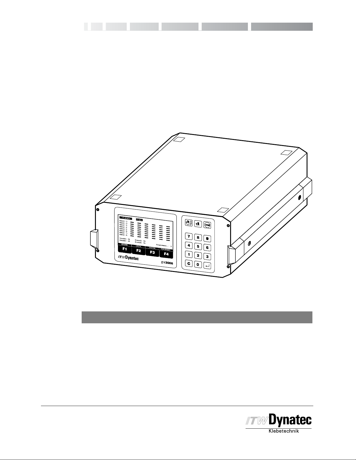
DY 2008
Pattern Controller
2008 D.BOO 11/02
For an online copy of this manual, go to www.itwdynatec.com/manuals.htm
ITW Dynatec
An Illinois Tool Works Company
31 Volunteer Drive
Hendersonville, TN 37075 USA
Telephone +1 615 824 3634
FAX +1 615 264 5222
dynatec@itwdynatec.com
www.itwdynatec.com
ITW Dynatec K.K.
Daiwashinagawa Bldg., 7-15 Konan, 3-Chome
Minata-Ku, Tokyo 108 Japan
Telephone 81 3 3450 5901
FAX 81 3 3450 8405
info@itwdynatec.co.jp
Page 2

Page 3
Page 4

Page 5

C. 2002
Manual #50-14 Revised 3/05
1: Safety Instructions 1 - 1...........................................
About this Manual 1 - 1...........................................................
Proper Use of System 1 - 1........................................................
Manual Symbols 1 - 1............................................................
Authorized Use of System 1 - 1....................................................
Installation, Maintenance, Repair or Disposal of the System 1 - 1.......................
Modification to the System 1 - 2....................................................
Working with Cover Open 1 - 2....................................................
2: Product Description 2 - 1..........................................
General 2-1....................................................................
Technical Data 2-2..............................................................
Dimensions (Basic version) 2 - 4...................................................
Operating and Connecting Elements (Basic version) 2 - 4.............................
3: Installation 3 - 1..................................................
Connectors and Pin Definitions 3 - 1................................................
Connecting the System 3 - 2......................................................
Locating an Optical Trigger (Sensor) 3 - 2...........................................
Connecting Optional Accessories 3 - 3..............................................
I
4: Operating 4 - 1...................................................
Operator’s Panel 4 - 1............................................................
Remote Purge Control 4 - 2.......................................................
Service Settings Menus 4 - 3......................................................
Production Setup Menu 4 - 4......................................................
Power On and Software Version 4 - 5...............................................
Service Settings 4-6.............................................................
Service Settings Menu 1 of 3 Overview 4 - 6..............................................
Service Settings Menu 2 of 3 Overview 4 - 8..............................................
Service Settings Menu 3 of 3 Overview 4 - 9..............................................
Factory Defaults 4-9..................................................................
Service Setting Programming Conventions 4 - 11.....................................
Display Contrast Adjustments 4 - 11.................................................
Service Settings Menu 1 4 - 12.....................................................
Select Language 4-12..................................................................
Load Program 4-13....................................................................
Trigger Assignment 4-14................................................................
Trigger Lock 4-15......................................................................
Encoder--Channel Assignment 4 - 15......................................................
Encoder Scaling (Encoder Type and Unit) 4 - 17............................................
Min/Max Speed Configuration 4 - 18.......................................................
Channel Mode Adjustment 4 - 19.........................................................
Change Security Lock 4 - 22.............................................................
Change Access Code 4 - 22.............................................................
Service Settings Menu 2 4 - 23.....................................................
Trigger Setup 4-23.....................................................................
Pressure Signaling 4-24................................................................
Pressure Assignment 4-25..............................................................
Pressure Curve Configuration 4 - 25.......................................................
Page 6

II
Manual #50-14 Revised 1/09
Spike Voltage Adjustment 4 - 27..........................................................
Spike Duration Adjustment 4 - 28.........................................................
Shutter Assignment 4-29...............................................................
Shutter Dwell Timing Adjustment 4 - 30....................................................
Change Security Lock 4 - 31.............................................................
Change Access Code 4 - 31.............................................................
Service Settings Menu 3 4 - 32.....................................................
STOP Configuration 4-32...............................................................
PC--Communication (Option) 4 - 33.......................................................
Change Profibus Address (Option) 4 - 33..................................................
Shutter Trigger Setup 4-34..............................................................
Digital Configuration 4-35...............................................................
Load Factory Defaults 4 - 37.............................................................
Change Security Lock 4 - 39.............................................................
Change Access Code 4 - 39.............................................................
Production Setup 4 - 40............................................................
Stop Function 4-41....................................................................
Glue Pattern Setup 4-42................................................................
Copy/ Paste Function 4-44..............................................................
Pressure Adjustment 4 - 45.........................................................
Adjust Minimum Pressure (2--Point Curve) 4 - 45............................................
Adjust Maximum Pressure (2--Point Curve) 4 - 45...........................................
Adjust Purge Pressure (2--Point Curve) 4 - 46..............................................
Assigning the Pressure Points to the Machine Speed (12--Point Curve) 4 - 46...................
Adjust Purge Pressure (12--Point Curve) 4 - 47.............................................
System Menus: Dot Function, Stitching and Head Position 4 - 48........................
Dot Configuration 4-48.................................................................
Stitching Configuration 4 - 50.............................................................
Offset (Head Position) 4 - 52.............................................................
Speed Compensation Adjustment 4 - 54.............................................
Manual Gluing (Purge) 4 - 55......................................................
C. 2002
5: Troubleshooting 5 - 1.............................................
Error Messages of the DY 2008 5 - 1...............................................
Communication Error 5-1..............................................................
Over Current Failure 5-1...............................................................
Compensation Error 5-1...............................................................
Appendix A
Common Accessories App. A 1........................................................
Appendix B
Printed Circuit Boards and Wiring Information App. B 1...................................
Appendix C
Programming Log App. C 1...........................................................
Page 7
C. 1998
Manual #50-14 Revised 1/03
1-1
Safety Instructions
Authorized Use of System
Only authorized persons who have read and understood the instruction manual or who
have been trained by ITW Dynatec may install, operate or dispose off this system.
Appropriate electrical safety procedures must be observed.
A copy of this manual should be kept with the installed system as reference material.
Proper Use of the System
This controller is designed for use only with ITW Dynatec hot melt or cold glue systems.
Other applications should be attempted only after consulting with ITW Dynatec.
Manual Symbols
Caution
This symbol means that failure to observe the specific instructions could
cause damage to the equipment.
Danger! High Voltage!
This symbol means there is a danger of electrical hazard.
Note! Provides useful information regarding the use of the system.
Page 8

1-2
C. 1998
Safety Instructions
Manual #50-14 Revised 1/03
Modifications to the System
No modification can be made to the system without consulting ITW Dynatec. Use only
factory--recommended parts and fittings. ITW Dynatec does not assume any resonsibility
for damage which occurs as a result of using parts that are not factory recommended.
Working with the Cover Open
Never operate this controller with open cover. There are no servicable components inside.
All settings are done via Software.
Inside the controller are electric current--carrying components. To avoid personal injury, do
not touch them while input power is ON. Disconnect and lockout main power before opening
the cover. Then wait a few seconds until all electrical components have discharged.
Page 9

C. 2002
Manual #50-14 Revised 1/03
2-1
Product Description
General
The DY 2008 Pattern Controller is one component of an adhesive application system
consisting of a hot-melt unit, cold glue pressure vessel or cold glue pump, adhesive hoses
and applicator heads. The controller can be used for hot--melt or cold glue application.
The pattern controller activates solenoids for four (Basic Version) up to 128 (Option)
applicator heads in order to create individual adhesive patterns. It is possible to program
up to 16 independent glue events (16 glue + 16 delay) per channel.
Each channel can operate in one of the possible modes: glue beads, dots, continuous
gluing, random product length and stitching.
Gluing can be triggered with a photo eye, proximity switch or by exceeding a certain
machine speed.
Every channel may be assigned to its own trigger input, if desired, to increase the accuracy
of multiple parallel running products.
In order to accelerate the timing of solenoids it is possible to apply initially a higher voltage
(Over--excitation). The voltage level and the duration time of this over--excitation is
programmable via software on a channel-by-channel basis. This enables applications for
hot--melt and cold glue.
The speed of the production machine will be registered with up to four encoders and
indicated on the display. It can be used to control the speed of one or more gear pumps of
adhesive supply units or to control the glue pressure on a cold glue system via I/P or U/P
transducers. Every time the machine speed varies the glue pressure will follow.
Working with four encoders enables application on machines with different speeds e.g.
Right--Angle machine.
The pressure vs. speed ramp can be linear or for better adaptation to production conditions
a 12--point curve is programmable.
A machine contact is available to enable or disable the controller. With this contact it is
possible to start and stop the gluing together with the parent machine.
The user can select whether the gluing stops immediately or continues.
The controller can provide an output signal to close a shutter devise (automatic tip sealer)
in order to prevent clogging of cold glue applicators from drying during production breaks.
If necessary this shutter output can be activated with a dedicated trigger input.
Alternatively the programming of the glue pattern can be done on a computer and
corresponding software. An optional RS232/485 or Profibus interface can be used to
communicate with the pattern controller from an external device.
Critical conditions can be signalled by means of two alarm outputs.
Page 10
2-2
C. 2002
Product Description
Manual 50-14 Revised 11/15
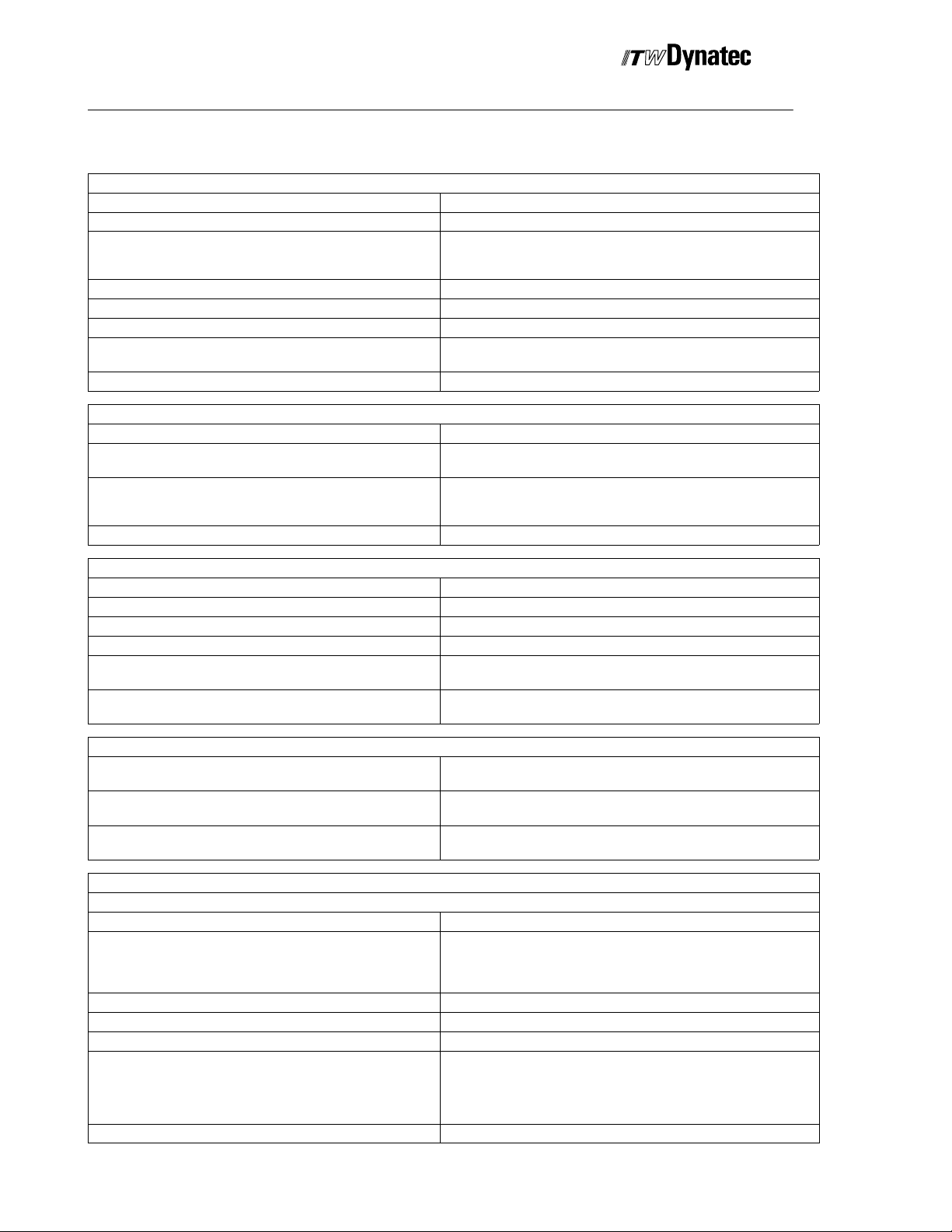
Technical Data
General
Operating Temperature
Storage Temperature
Power Supply 1/N/PE 230 V 50--60 Hz
Power Consumption 180w (8 channel version)
Operating Languages German, English, Finnish, French, Italian
Number of Programs 60 stored in permanent memory
Protection Class IP 40
CE Approval Granted yes
Trigger
Input connectors 24 V DC, max. 100 mA, NPN, PNP, Push--Pull
Max. Number 4 Master Triggers (Triggers #1 thru 4)
Assignment (every channel can be assigned to a Master
Trigger or its Channel Trigger and any trigger may be “Anded”
to a Master Trigger)
Trigger Lock 0--8000 mm (0.01 to 80.00 in)
0 °Cto+50°C(32°F to122 °F)
-- 1 0 °Cto50°C(32°F to122 °F)
1/N/PE 115 V 50--60 Hz
1/N/PE 200 V 50--60 Hz
(Option IP 54)
1 additional per channel (Channel #5 and above)
Every Trigger can be assigned to each of the channel
Via AND--Function multiple Triggers can be combined.
Encoder
Max. Number 4
Input connectors X17 and X18 24 V DC, max. 100 mA, NPN (scalable)
Assignment Any encoder can be assigned to any channel.
Configuration Metric or inch
Scaling
Indication of Production Machine Speed max. 1200 m/min (2000 pulses/m)
Speed Configuration
Start Gluing above (Vmin START) 0--999 m/min
Stop Gluing below (V min STOP) 0--999 m/min
Maximum Machine Speed (V max) 0--1200 m/min
Output (Valve Output)
Channel X1 to X4 (Basic Version) for Controlling of Solenoids Valves (Short circuit proof)
Max. Number 4 (Option max. 128)
Output Voltage Nominal: 24 V DC
Overexcitation Timing 0.5--2.5 ms adjustable per software in steps of 0.5 ms
Wattage Capacity per Channel max. 20 W
Total Wattage Capacity for Channels 1--8 max. 160 W
Speed Compensation 0--999 mm
1--4000 pulse/m
0.01--99.99 pulse/inch
4000 ft/min (50 pulses/inch)
0--999 ft/min
0--999 ft/min
0--4000 ft/min
Overexcitation:
55 V (Factory Default) or 170 V
all Channels are individually adjustable
9.99 inch
Page 11

C. 2002
2-3
Manual #50-14 Revised 11/14
Valve M od e
Standard Mode Glue pattern, with or without stitching, is initiated by a trigger
signal. Gluing at speeds between Vmin and Vmax
Standard with Dot-Mode Glue pattern, with or without stitching, is initiated by a trigger
signal. Gluing at speeds between V-min START and V-min STOP
is Dot Mode. Gluing at speeds above V-min STOP is Standard
Mode.
Dot Mode Dot- Mode between Vmin and Vmax
Random Product Length Automatic adjustment of the pattern length to different product
length. Start and Stop of the pattern is controlled with a trigger
signal. Pattern can be stitched or continuous.
Continuous Gluing with Trigger Continuous gluing controlled with a trigger signal (i.e. glue active
when trigger active). Gluing starts above 1 m/min or 1 ft/min
Continuous with Trigger and Low Speed Cut Off Continuous gluing controlled with a trigger signal (i.e. glue active
when trigger active).Gluing starts when machine speed between
Vmin and Vmax
Continuous Gluing with Low Speed Continuous gluing starts at machine speed between Vmin and
Vmax, no trigger input is required
Glue Pattern
Maximum selectable Pattern and Delay Length 0- 8000 mm in steps of 1 mm
0- 80.00 inch in steps of 0.01 inch
Stitching: Glue Bead and Break Length 1- 200 mm in steps of 1 mm
0.01- 2.00 inch in steps of 0.01 inch
Dot Mode Breaks:
1- 8000 mm in steps of 1 mm
0.01- 9.99 inch in steps of 0.01 inch
Dot Length:
0.10- 9.90 ms
Product Description
Pressure Control Output
Max. Number 4
Connectors X24 to X27 4- 20 mA or 0- 20 mA and 0- 10 V scalable
Assignment Each Pressure Control Output can be assigned to any Encoder
Pressure Range min/max-Limits 0 to 100 %
Pressure Control Mode 2- or 12- Point Curve
Shutter Control
Output Connector X23 24V DC, max. 2 A
Trigger Input X20 Controlled by dedicated input or one of the Master Triggers
Machine contact, Alarm outputs and Interfaces
Machine contact X19 NPN, normally open contact required
Ready- /Alarm output connector X21 Normally open / normally closed, potential- free 24V DC, max. 500
RS232/485 Interface Connector X30 Option
Profibus Connector X28, X29 Option
mA or 230V AC, max. 500 mA,
Page 12

2-4
C. 2002
Product Description
Dimensions (Basic Version, 4 or 8 Channels)
0 m/min
Kanal 1:
Kanal 2:
Kanal 3:
Kanal 4:
Kanal 5:
Kanal 6:
Kanal 7:
Kanal 8:
Druck1: 0%
Druck3: 0%
Druck2: 0%
MUSTER DRUCK SYSTEM KOMPENSAT.
F1 F2 F3 F4
Programm.: 1
Druck4: 0%
DY 2008
241.3mm (9.5”)
279.4mm (11”)
326mm (13”) 345 mm (14”)
Operating and Connecting Elements (Basic Version)
Manual 50-14 Revised 7/03
150mm (6”)
Operating Panel
Connectors
Main Switch
Power Inlet
Page 13
C. 1998
Manual #50-14 Revised 1/03
Installation
Caution!
Only authorized person should execute the following procedures. Observe
all applicable safety rules.
Danger!
Place this controller in a dry and dust-free environment and not in the
danger zone of other machines. The operating elements must be accesable
without hazards.
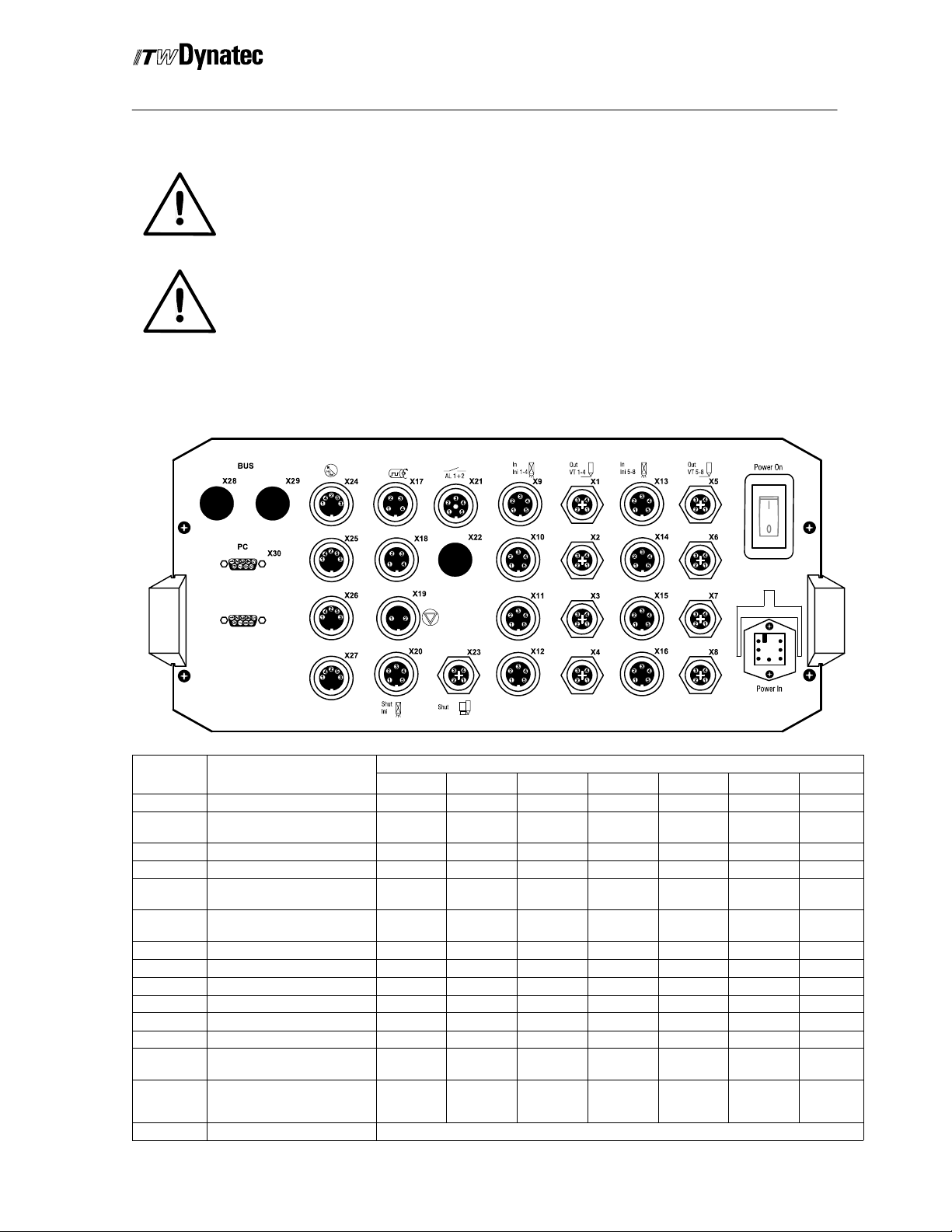
Connectors and Contact Definitions
6
3--1
REMOTE
X31
Connector Function
X1--X8 Output for Solenoids 1 to 8 + -- Shield
X9--X16 Trigger 1 to 8 GND +24 V
X17 Encoder 1 and 3 GND +24 V Encoder 1 Encoder 3
X18 Encoder 2 and 4 GND +24 V Encoder 2 Encoder 4
X19 Machine contact GND
X20 Trigger for Shutter Control GND +24 V
X21 Alarm/ Zero Speed N.O. Common N.C.
X21 Stop/ System Ready N.O. Common N.C.
X22 Not Used
X23 Shutter Output + -- Shield
X24--X27 Pressure Control Output GND 0(4)-20mA 0-10 V +24 V
X28 Profi--Bus Connector Male Bus A Bus B Shield
X29
X30
X31 Remote Control RS 485 only for ITW Dynatec Remote Control
Profi--Bus Connector
Female
PC--Interface RS 232
or RS 485
1
5VDC Bus A GND Bus B Shield
2 3 4 5 6 7
Signal
NPN
TXD (232)
B (485)
Contact Definition
Signal
NPN/PNP
Signal
NPN/PNP
RXD
(232)
GND
A (485)
Page 14

3--2
C. 2002
Installation
Manual #50-14 Revised 8/2008
Connecting the System
Caution!
The over-excitation (spike) voltage for the outputs is shut off as a factory
default. Make sure this voltage is set appropriately for the applicator heads
being used. If necessary change the over-excitation as per instructions
provided in Chapter 4 of this manual.
Note! ITW Dynatec DynaCold and DynaCold Mini applicators always require an
over-excitation voltage of 170V.
(1)
1. Plug all connectors in the corresponding
receptacles.
2. Engage the locking ring (1) of the connector plugs
to the receptacles.
3. Connect the controller to the power supply.
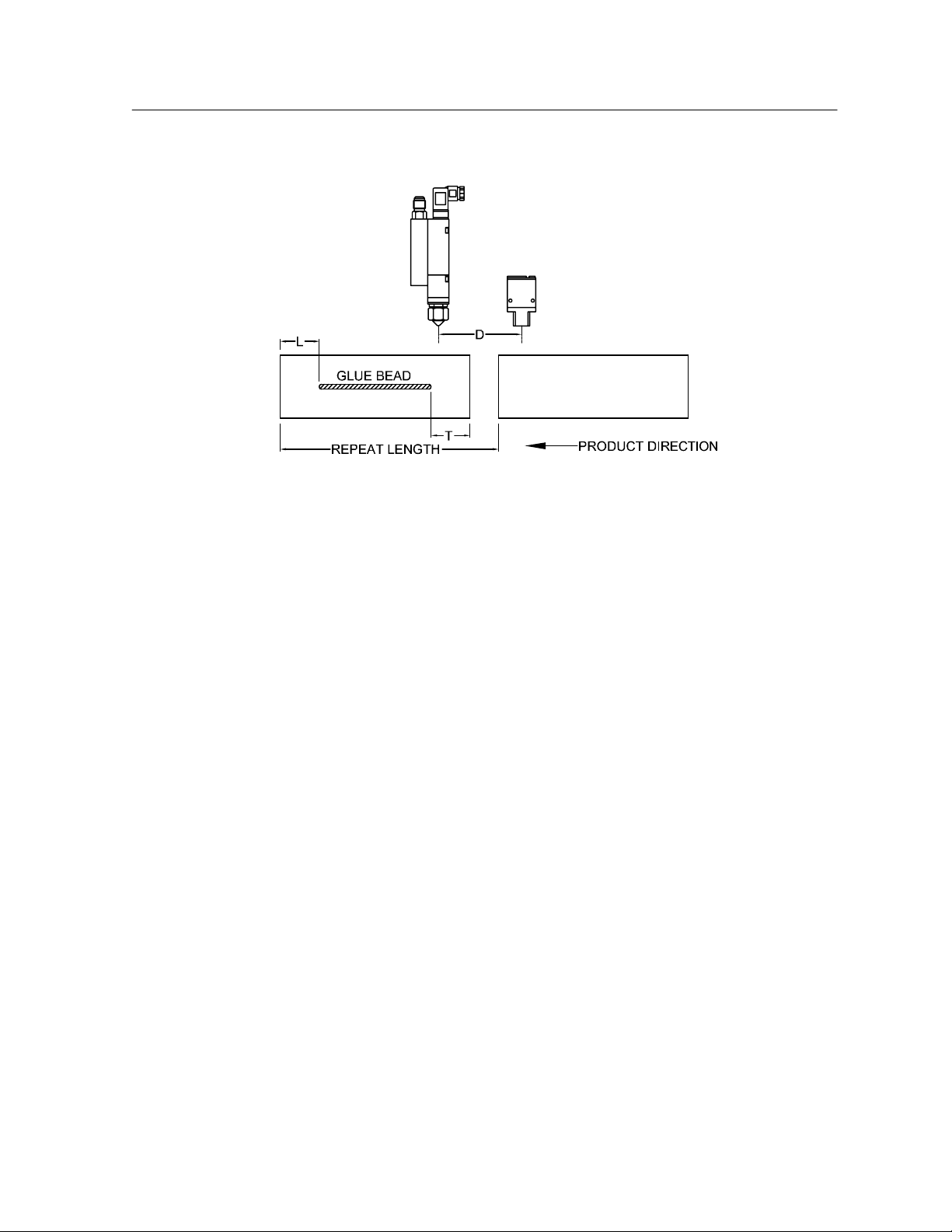
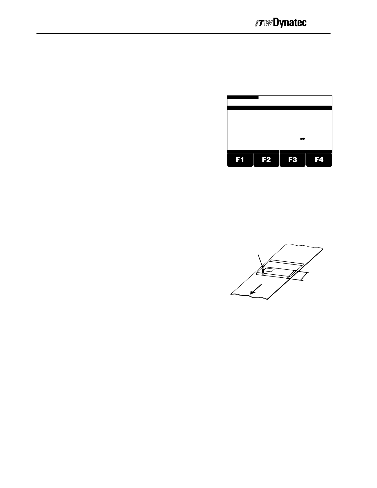
Locating an Optical Trigger (Sensor)
Use the information below to assist in the proper location of an optical triggering device.
TRIGGER LOCATION GUIDELINES (All Conditions Must Be Met)
All Intermittent Modes Except RANDOM
D + L > On Compensation
D < Repeat Length
RANDOM Mode
D + L > On Compensation
D > T + Off Compensation
D < Repeat Length
D = Distance from Optical Sensor to Glue Applicator (i.e. OFFSET)
L = Leading gap on product prior to first glue bead application.
T = Trailing gap on product after last glue bead application.
See the following diagram for additional clarification on this subject.
Page 15
C. 1998
3--3
2008 D 12/98
Manual #50-14 Revised 3/2005
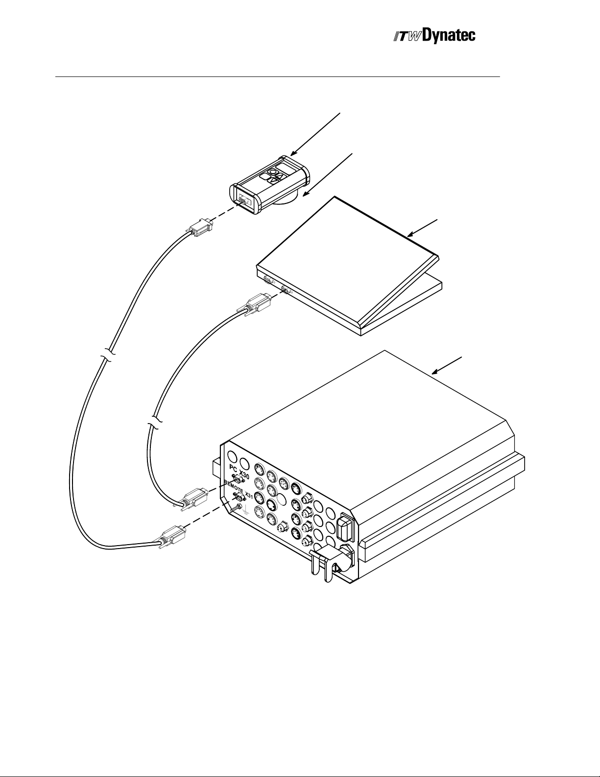
Connecting Optional Accessories
Installation
The DY2008 may be supplied with optional accessories as follows:
1. Remote Front Panel (28.11101.601): this allows the DY2008 operator interface to be
installed up to 10 meters (33 feet) away from the main control box. This is provided as an
option for the four and eight channel units and is standard for 12 or more channel units.
2. Remote Purge Control (28.11101.602): this allows one-person operation of the manual
gluing (purge) function at distances up to 10 meters (33 feet) from the Main Control Unit or
Remote Front Panel (if installed).
3. Data Interface Option (28.00005.107): this provides the ability to control the
programming of the DY2008 from another CPU via a RS232 or RS485 data interface.
Use the diagrams that follow as a guide in connecting the above accessories to the DY2008
Control Unit.
Page 16
3--4
C. 2002
Installation
Manual #50-14 Revised 8/2008
Purge Control
Magnet mount
PC
DY 2008
ConnectingOptions Directlyto Control Unit
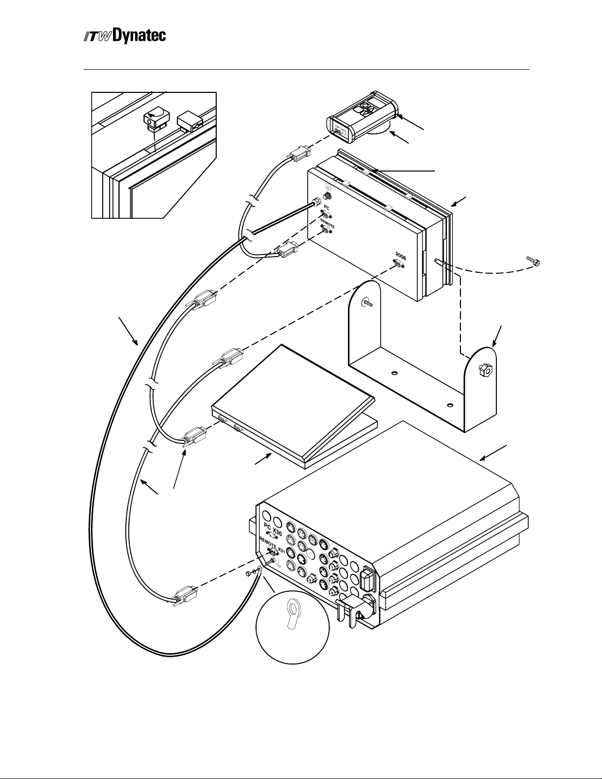
Page 17
C. 1998
3--5
2008 D 12/98
Turn mounting
clip clockwise in
slot.
Ground Wire
Manual #50-14 Revised 3/2005
Installation
Purge Control
Magnet mount
Mounting Clip (used
for panel mounting)
Remote Panel
Remove screw
to attach Mounting
Bracket.
Remote Panel
Mounting Bracket.
Data Cable
DY 2008
PC
Attach terminal
to ground wire
Connecting Options Through Remote Front Panel
Page 18

3--6
C. 2002
Installation
Manual #50-14 Revised 8/2008
ITW Dynatec
An Illinois Tool Works Company
Page 19
Operation
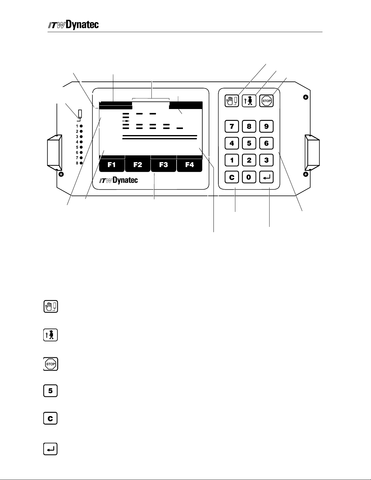
Operator’s Panel
Machine Speed
Encoder 2 Encoder 1
C. 1998
Manual #50-14 Revised 8/08
COM-STOP
COM 2-STOP
BUS-STOP
STOP
EXTER.STOP
All Channels stopped via serial interface
All Channels stopped via Purge Control
All Channels stopped via Profi--Bus
All Channels manually stopped
Stop cause by external contact
Page 4-- 1
Manual Gluing (Purge)
Service Menu
Manual Stop
LEDs Signal
Activation of the
Valve Outputs
Pressure Indication
1: 0 m/min
2: 0 m/min
C1:S
C2:S
C3:D
C4:S
C5:S
C7:C
C8:R
PRESS1: 0%
PRESS2: 0%
PATTERN SYSTEM COMP.
PRESS3: 0%
PRESS4: 0%
PRESSURE
Function Keys
Glue Pattern:
Channel 1: 3 Glue Events
Channel 2: 1 Glue Event
Channel 3: Dot Mode, 1 Event
Channel 4: 4 Glue Events
Channel 5: 5 Glue Events
Channel 6: Turned Off
Channel 7: Continuous Gluing
Channel 8: Random Length Gluing
S: Trigger Indication for Standard Mode Gluing
C: Trigger Indication for Continuous Mode Gluing
D: Trigger Indicator for Dot Mode Gluing
R: Trigger Indication for Random Mode Gluing
Function Keys F1, F2, F3, F4
STOP
EXTER.STOP
Encoder 3
3: 0 m/min
4: 0 m/min
Encoder 4
PROGRAM:
DY2008
1
Clear Button
Program Number
Numeric Keys
Enter Button
These keys can have changing functions. The lower line of the display above
the keys will indicate the current function.
Manual Gluing (Purge) Button
This button is used to activate the valve outputs manually. It is possible to select individual
channels. The button operates only when manual stop (see below) mode is activated.
Service Button
Use this button to open the configurationmenu. The button operates only when manual stop (see
below) mode is activated.
Stop Button
Pressing this button will stop gluing. “STOP” will flash at the top, center of the display when this
mode is active.
Numeric Keys
Use these keys to enter parameter values.
Clear Button
Pressing this button will reset a parameter to the previously programmed value or to “0” (zero),
depending upon the specific parameter.
Enter Button
This button is used to confirm a new entry.
Page 20
Page 4-- 2
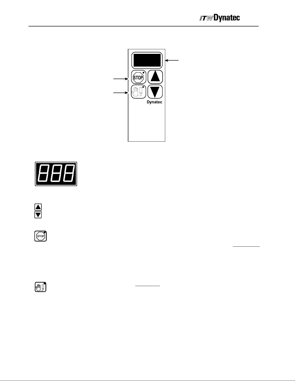
Remote Purge Control
Manual #50-14 Revised 8/08
Channel
Indicator
C. 1998
Stop Button
Manual Gluing
Button
Channel Indicator
Channel Select Buttons
Use the “increment” or “decrement” button to change the current channel displayed in the
Channel Indicator.
Channel
Select
}
Purge Control
Displays the current channel selected from the Remote Purge Control Unit.
Stop Button
Used to place the control into a STOP condition for manual gluing activation. Also causes the
pressure output circuitry (X24 through X27) to output programmed PURGE PRESSURE when
STOP is activated. STOP activation is indicated by an amber LED that is continuously
illuminated. See the section of this chapter on Stop Conditions for more detail. Deactivating
STOP will also automatically cease manual gluing operations on any channels that are still
active.
Manual Gluing (Purge) Button
Used to activate (amber LED on continuously) or deactivate (amber LED is either OFF or
flashing) the current channel displayed in the Channel Indicator LED’s.
Mounting Note
A magnet is attached to the back side of the Remote Purge Control unit for convenient mounting to any ferrous
metal object.
Page 21
C. 1998
Manual #50-14 Revised 8/08
Page 4-- 3
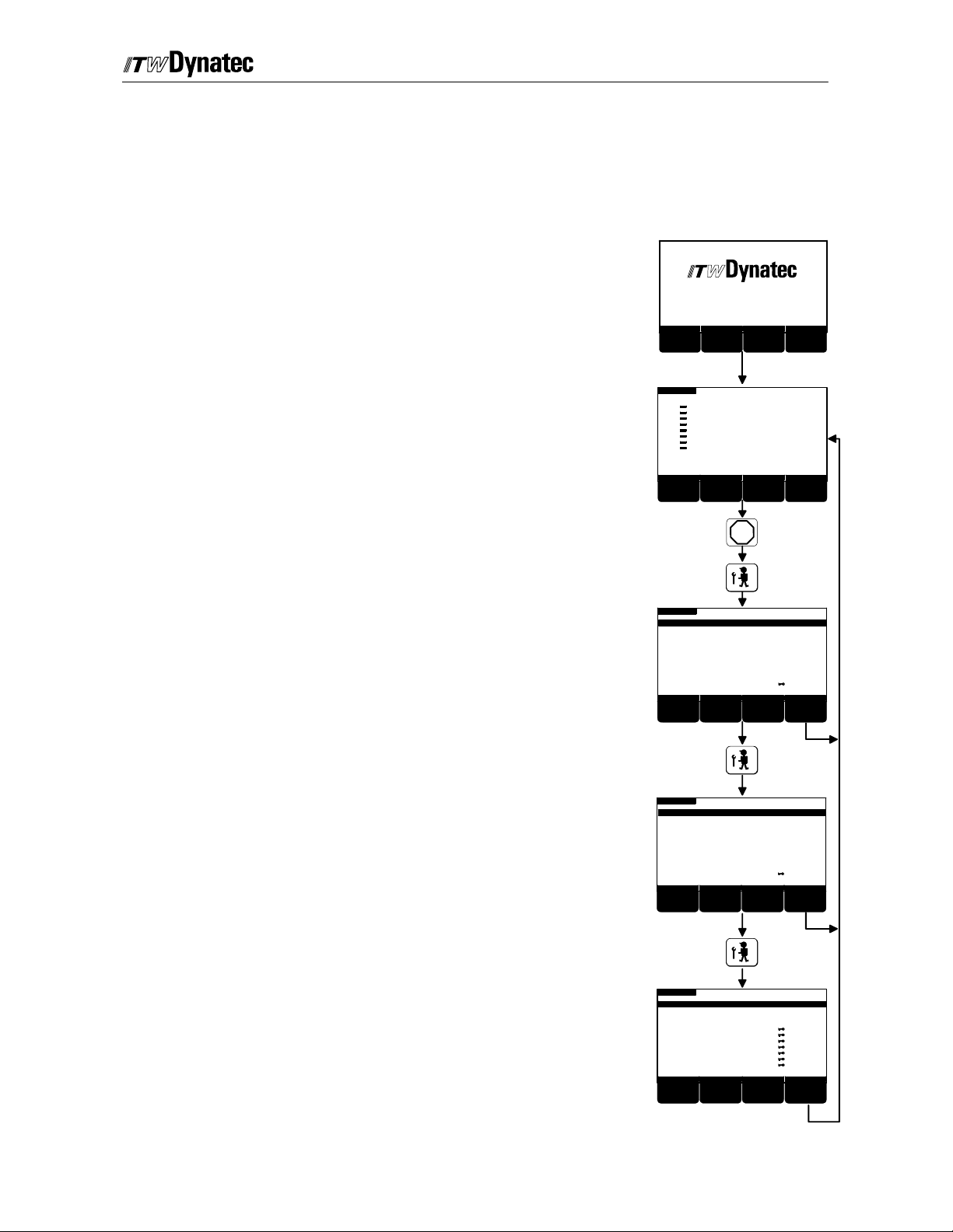
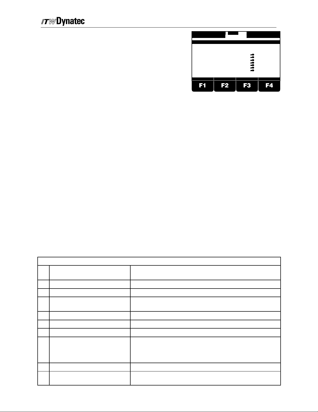
Service Setting Menus
Changing these settings may be neccesary during initial installation or after modification
to the system. After pressing the Stop button, these menus are selectable with the Service
button. The following settings are some of the available selections:
Turn power on to the control unit.
Adhesive Applic ation S ystems
Version: V2.xx
INITIALIZING CHANNEL
F1 F2 F3 F4
0 m/min
The Main Menu will come up after a few seconds
K 1:C
K2:
K3:
c4:
K5:
KC6:
K7:
K8:
PRESS1: 20%
PRESS2: 10%
Pattern
PRESS3: 10%
PRESS4: 10%
Pressure
Programm: 1
System
F1 F2 F3 F4
Compensat.
Press the Stop button,
and then the Service Settings Button.
Service Settings Menu 1 appears.
Select the desired parameter menu with the numeric
keys and procede with programming.
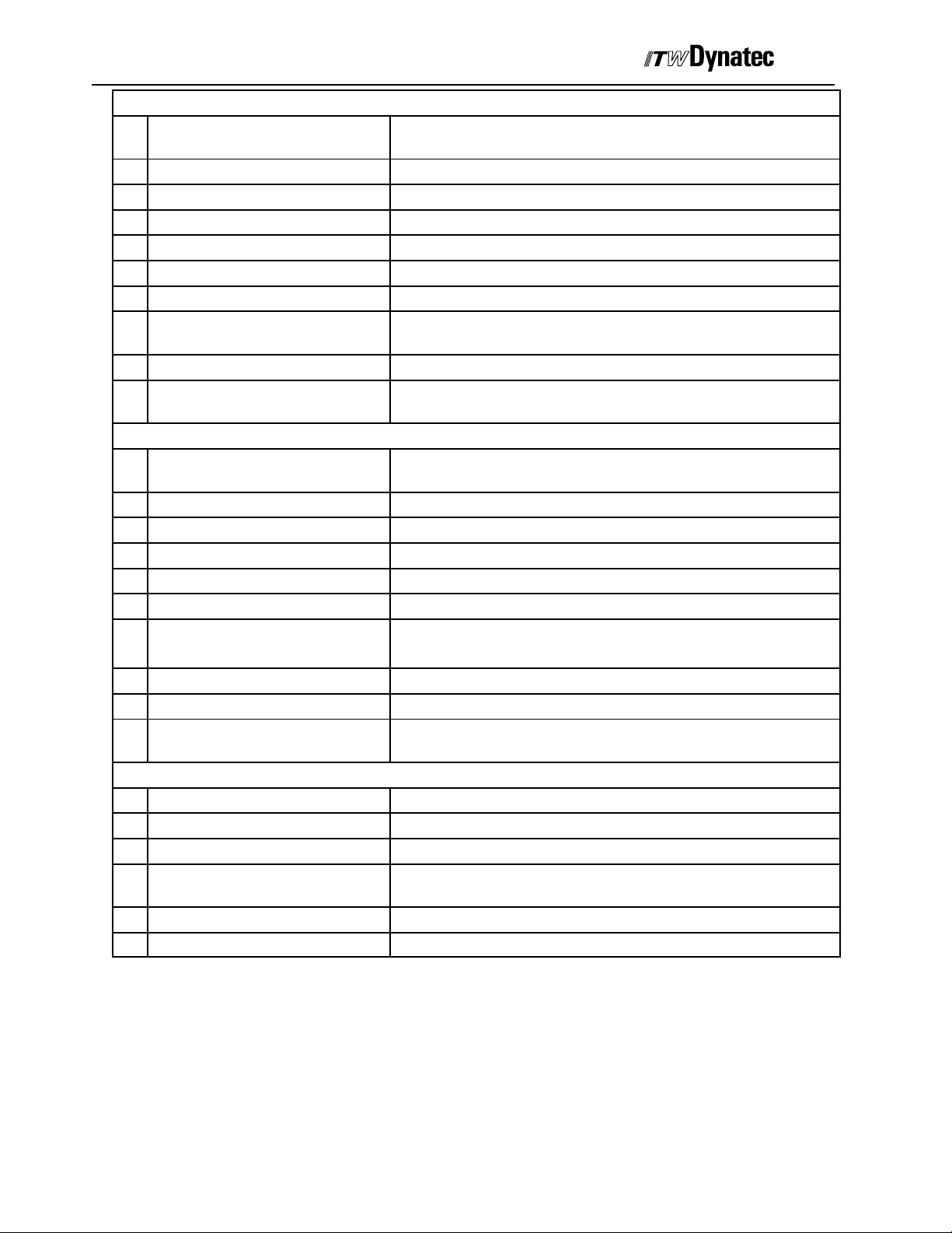
Press the Service Settings key again
Service Settings Menu 2 appears.
Select the desired parameter menu with the numeric
keys and procede with programming.
Press the Service Settings button again
Service Settings Menu 3 appears.
Select the desired parameter menu with the numeric
keys and procede with programming.
STOP
0 m/min
LANGUAGE
LOAD PROGRAM
CHANNEL : TRIGGER
TRIGGER LOCK
CHANNEL : ENCODER
ENCODER SCALING
MIN/MAX SPEED SET.
CHANNEL MODE
CHANGE SECURITY LOCK
CONTRAST+
STOP
SERVICE SETTINGS 1 OF 3
CONTRAST-
--
1
--
2
--
3
--
4
--
5
--
6
--
7
--
8
--
9
F1 F2 F3 F4
0 m/min
SERVICE SETTINGS 2 OF 3
TRIGGER SETUP
PRESSURE SIGNALING
PRESSURE ASSIGNMENT
PRESSURE CURVE
SPIKE VOLTAGE
SPIKE DURATION
SHUTTER ASSIGNMENT
SHUTTER DWELL TIME
CHANGE SECURITY LOCK
CONTRAST +
CONTRAST-
STOP
--
1
--
2
--
3
--
4
--
5
--
6
--
7
--
8
--
9
F1 F2 F3 F4
0 m/min
STOP-CONFIGURATION
PC-COMMUNICATION
PROFIBUS ADDRESS
RESERVE
RESERVE
RESERVE
RESERVE
LOAD FACTORY SETUP
CHANGE SECURITY LOCK
CONTRAST+
STOP
SERVICE SETTINGS 3 OF 3
CONTRAST-
--
1
--
2
--
3
--
4
--
5
--
6
--
7
--
8
--
9
F1 F2 F3 F4
RETURN
RETURN
RETURN
123
123
123
Use button F4 to return to the Main menu at any time.
Page 22

Page 4-- 4
Production Setup Menu
Switch Power on
Manual #50-14 Revised 8/08
C. 1998
Main Menu appears after a few seconds
Glue Pattern Set --up
or
0%
100%
0%
ZURUECK
SYSTEM
F3 F4
Pressure Configuration (Linear)
Pressure Configuration(12--Point Curve)
Display shows machine speed and glue pattern
Pressure and program number
System Configuration
Valve--Compensation
Dot Configuration
Menu Structure of the Production Settings
Stitching Configuration
0 m/min
LADE
Head Position
ZURUECK
SYSTEM
Page 23
C. 1998
Manual #50-14 Revised 8/08
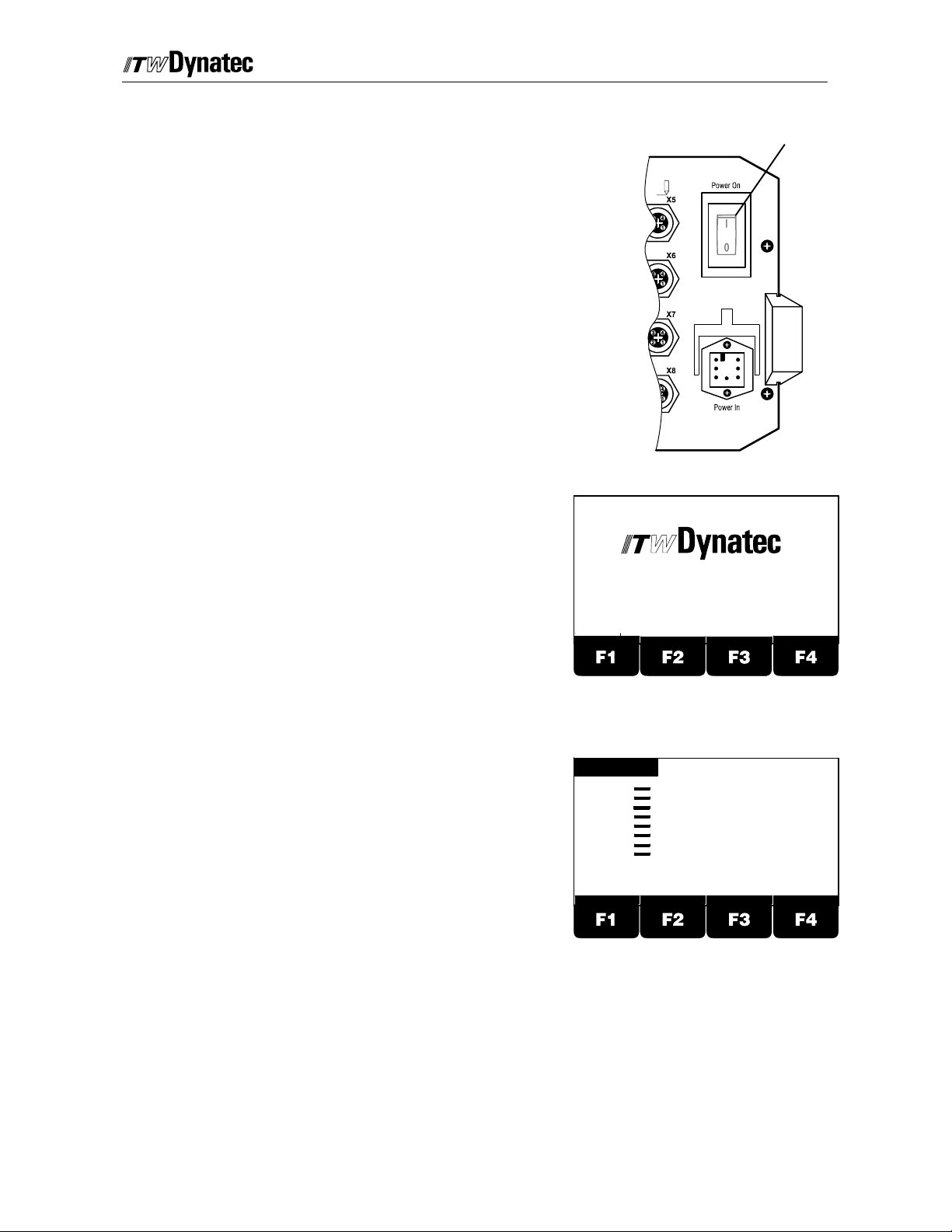
Power (Switch) On and Software--Version Indication
Page 4-- 5
The main power switch is located at the back side of the
controller.
After the controller is switched on the display shortly
indicates the ITW Dynatec logo and the Software
revision.
Main Switch
Back Side
Adhesive Application Systems
After a few seconds the screen will display the Main
Menu.
Vers io n 2 .X X
INITIALIZING CHANNEL
PATTERN
1: 0 m/min
Channel 1:
Channel 2:
Channel 3:
Channel 4:
Channel 5:
Channel 6:
Channel 7:
Channel 8:
PRESS1: 0%
PRESS2: 0%
PATTERN PRESSURE SYSTEM
PRESS3: 0%
PRESS4: 0% PROGRAM: 1
COMP.
Page 24
Page 4-- 6
Manual #50-14 Revised 8/08
Service Settings
Modification of these settings will be necessary at initial
installation or after modifications to the system. After
pressing the Stop button the menus can be selected
with the Service button.
C. 1998
Service Settings Menu 1 (of 3) Overview
1 Language: Use this menu to select the
language. All display texts will appear in the
selected language.
2 Load Program: Use this menu to store all
settings within one of 60 available programs or
recall a previously saved program.
3 Channel: Trigger: Use this m enu to determine
which trigger should be assigned for the selected
channel or to deactivate this channel. It is also
possible to combine with an additional trigger via
AND--function. In this case that channel will be
triggered only when both trigger inputs are active.
4 Trigger Lock: This function determines for what
length of distance after a trigger signal additional
trigger signals will be ignored . This function can
be necessary gluing products with cut-outs (e.g.
envelopes with window).This will prevent the
detection of the window from triggering a new
glue cycle. It is possible to select values between
1 and 9999 mm (0.01 and 99.99 inch).
1: 0 m/min
CONTRAST +
STOP
SERVICE SETTINGS 1 OF 3
LANGUAGE
LOAD PROGRAM
CHANNEL : TRIGGER
TRIGGER LOCK
CHANNEL : ENCODER
ENCODER SCALING
MIN/MAX SPEED SET.
CHANNEL MODE
CHANGE SECURITY LOCK
CONTRAST-
Window
Envelope
Code
1
--
2
--
3
--
4
--
5
--
6
--
7
--
8
--
9
123
RETURN
Trigger Lock
5 Channel: Encoder: Use this menu to assign one of the encoder inputs to each
channel.
6 Encoder Scaling: Use this menu to configure the installed encoder. Program the
number of pulse per meter (inch). If metric unit is selected, all distances will be
shown in mm and all speed indications will be shown in m/min. If inch is selected, all
distances are shown in inch and all speed indications are shown in ft/min.
7 Min/Max Speed Set: This menu determines the speed conditions for start and stop
of gluing.The start is valid for increasing speed and stop for decreasing speed.
Additionally the maximum machine speed can be selected. This value is used to
determine the pressure output curve and valve compensation.
8 Channel Mode: Use this m enu to select the valve mode. The following modes are
available:
Standard, Standard with Dot, Dot, Random Product Length, Continuous with
Page 25

C. 1998
Manual #50-14 Revised 8/08
Page 4-- 7
Trigger, Continuous with Trigger and Speed, Continuous with Speed (Vmin).
9 Change Security Lock: This menu is used to lock individual functions to prevent
unauthorized modification. Additionally it is possible to change the access code. You
can lock/unlock every above mentioned function. After locking, these functions are
only available via access code. Locking/Unlocking is only possible if you know the
access code.
Page 26

Page 4-- 8
Manual #50-14 Revised 8/08
C. 1998
Service Settings Menu 2 (of 3) Overview
1 Trigger Setup: Use this menu to select the
properties of the trigger devices used.That
means the NPN--PNP selection.
1: 0 m/min
2: 0 m/min
TRIGGER SETUP
PRESSURE SIGNALING
PRESSURE ASSIGNMENT
PRESSURE CURVE
SPIKE VOLTAGE
SPIKE DURATION
SHUTTER ASSIGNMENT
SHUTTER DWELL TIME
CHANGE SECURITY LOCK
STOP
SERVICE SETTINGS 2 OF 3
3: 0 m/min
4: 0 m/min
1
2
3
4
5
6
7
8
9
Code
--
--
--
--
--
--
--
--
2 Pressure Signaling: Use this menu to configure
the pressure control outputs. You can select from
CONTRAST+
CONTRAST-
RETURN
0--10VDC/ 0--20 mA or 4--20 mA.
3 Pressure Assignment: Use this menu to assign each of the pressure control
outputs to one of the encoders.
4 Pressure Curve: Use this menu to select between 2 or 12 point pressure curve.
5 Spike Voltage: You can select the overexcitation voltage 55V or 170V for each
channel, or you can deactivate the overexcitation for this channel.
6 Spike Duration: The duration time of the overexcitation is programmable between
0.5ms and 2.5ms.
7 Shutter Assignment: Use this menu to assign the shutter output (X23) to one of
the triggers.
123
8 Shutter Dwell Time: Use this menu to adjust the duration of time the shutter circuit
remains active after the last trigger input. Values range from 1 to 99 seconds.
9 Change Security Lock: This menu is used to lock individual functions to prevent
unauthorized modification. Additionally it is possible to change the access code. You
can lock/unlock every above mentioned function. After locking, these functions are
only available via access code. Locking/Unlocking is only possible if you know the
access code.
Page 27
C. 1998
Manual #50-14 Revised 8/08
Page 4-- 9
Service Settings Menu 3 (of 3) Overview
1 STOP--Configuration: Use this menu to select
the Stop Mode for each channel: Complete or do
not complete an interrupted gluing pattern upon
machine restart.
2 PC--Communication: Use this menu to select
1: 0 m/min
2: 0 m/min
CONTRAST+
STOP-CONFIGURATION
PC-COMMUNICATION
RESERVE
SHUTTER
RESERVE
DIGITAL
RESERVE
LOAD FACTORY SETUP
CHANGE SECURITY LOCK
STOP
SERVICE SETTINGS 3 OF 3
CONTRAST-
3: 0 m/min
4: 0 m/min
1
2
3
4
5
6
7
8
9
Code
--
--
--
--
--
--
--
RETURN
RS232 or RS485 data protocol and to adjust the
baud rate.
3 Reserve: This menu is not used.
4 Shutter Trigger Setup: Use this menu to select a NPN or PNP shutter trigger
device.
5 Reserve: This menu is not used.
6 Digital Configuration: Use this menu to configure the Machine Contact (X19) and
Alarm Output (X21).
7 Reserve: This menu is not used.
8 Load Factory Setup: In this menu you can reload the factory default for the active
program. After entering the access code the active program will be reset to the
values listed below.
9 Change Security Lock: This menu is used to lock individual functions to prevent
unauthorized modification. Additionally it is possible to change the access code. You
can lock/unlock every above mentioned function. After locking, these functions are
only available via access code. Locking/Unlocking is only possible if you know the
access code.
Factory Default Values
Service Settings Menu 1 of 3
No
Function Setting
.
1 Language English
2 Program As per operator selection
3 Trigger Assignment All Channels are assigned to Trigger 1.
The ’AND’--function is deactivated
4 Trigger Lock All Channels set to 1 mm (0.01 in)
5 Encoder Assignment All Channels are assigned to Encoder 1.
6 Encoder Scaling All Encoders are scaled to 1000 pulses/meter (10.00 ppi)
7 Speed Configuration All Encoders:
Gluing starts above 20 m/min (20 ft.min)
Gluing stops below 30 m/min (30 ft/min)
Maximum Machine Speed: 600 m/min (600 ft/min)
8 Channel--Mode All Channels are set to “Standard”
9 Security Lock Acc e s s co d e 1111, this function l o c ked
All previous functions are unlocked
Page 28
Page 4-- 10
Manual #50-14 Revised 8/08
Service Settings Menu 2 of 3
No
Function Setting
.
1 Trigger Setup All Triggers set to NPN
2 Pressure Signaling All Pressure outputs set to 4--20 mA
3 Pressure Assignment All Pressure outputs assigned to Encoder 1
4 Pressure Curve All Outputs set to 2--Point curve
5 Spike Voltage All Channels set to 55 V
6 Spike Duration All Channels set to 1.6 ms
7 Shutter Assignment The Shutter output (X23) is assigned to the shutter trigger
(X20)
8 Shutter Dwell Time 2sec.
9 Security Lock Acc e s scode 1111, th i s fu n c t i o n lo c k ed
All previous functions are unlocked
Service Settings Menu 3 of 3
No
Function Setting
.
1 STOP--Configuration All Channels: “NOT FINISH GLUING UPON RESTART”
2 PC--Communication As previously programmed
3 Reserve not used, Function locked
4 Shutter Trigger Setting NPN
5 Reserve not used, Function locked
6 Digital Configuration Machine Contact: Normally Open
Relay 1: Stop Relay 2: Alarm
7 Reserve not used, Function locked
8 Load Factory Default Function Locked
9 Security Lock Acc e s s co d e 1111, this function l o c k ed
All previous functions are unlocked
Production Menus
Function Setting
Pattern All Channels: Del.1 = 10mm (0.10 in), Glue 1 = 20 mm (0.20 in)
Pressure All Outputs: Min: 0%, Max: 100%, Purge: 70%
Stitch All Channels: Glue 4mm (0.04 in), Gap 4 mm (0.04 in), no stitch
functions are active
Offset All Channels: 20mm (0.20 in)
Compensation All Channels: ON: 0, OFF: 0
C. 1998
Page 29

C. 1998
Manual #50-14 Revised 8/08
Page 4-- 11
Service Setting Programming Conventions
The following programming conventions are employed in the Service Settings Menus:
123
RETURN
The “numeral” icon is displayed in the lower
right corner of the screen to indicate that the
numeric keypad should be used to enter the
desired value.
The “enter” icon is displayed in the lower
right corner of the screen to indicate that the
ENTER button (see page 4-1) should be
pressed in order to accept the selected
value.
Press the CLEAR Button on the numeric
keypad to revert a modified parameter to its
original value provided the ENTER button
has not already been pressed.
Press the RETURN (F4) button to go to the
next higher level of programming menus or
to undo a programming change as long as
the ENTER button has not been pressed.
1: 0 m/min
2: 0 m/min
ENCODER 1:
ENCODER 2:
ENCODER 3:
ENCODER 4:
STOP
ENCODER SCALING MENU
500
1000
1000
1000
inch
3: 0 m/min
4: 0 m/min
PULSES / Meter
PULSES / Meter
PULSES / Meter
PULSES / Meter
RETURN
123
Display Contrast Adjustments
The display brightness (contrast) is adjusted from any of the three Service Settings Menus
via the following procedure. Take care not to adjust the display too bright as this will tend
to reduce the life of the display.
1
2
3
4
5
6
7
8
9
3: 0 m/min
4: 0 m/min
Code
--
--
--
--
--
--
--
--
RETURN
123
CONTRAST +
CONTRAST-
This button is used to make the display
background darker.
This button is used to make the display
background lighter. NOTE: do not set the
display too bright as this will tend to reduce
the life of the display.
1: 0 m/min
2: 0 m/min
LANGUAGE
LOAD PROGRAM
CHANNEL : TRIGGER
TRIGGER LOCK
CHANNEL : ENCODER
ENCODER SCALING
MIN/MAX SPEED SET.
CHANNEL MODE
CHANGE SECURITY LOCK
CONTRAST+
STOP
SERVICE SETTINGS 1 OF 3
CONTRAST-
Page 30
Page 4-- 12
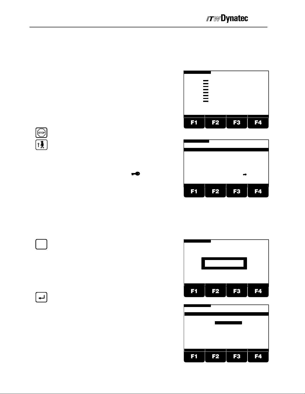
Manual #50-14 Revised 8/08
Service Settings Menu 1 (of 3) Programming
Note! The Service Settings Menu is only
accessible after activating the STOP
Button.
C. 1998
After the controller is switched on the
display shortly indicates the ITW Dynatec
logo and the Software revision.
After a few seconds the display changes
to the Main Menu. That means glue
pattern, pressure and program number will
be shown.
1: 0 m/min
C1:
C2:
C3:
C4:
C5:
C6:
C7:
C8:
PRESS1: 0%
PRESS2: 0%
PATTERN PRESSURE SYSTEM COMP.
PRESS3: 0%
PRESS4: 0%
PROGRAM:
1
Press the STOP Button.
Press the Service Button.
Select one of the listed functions by pressing the
corresponding numeric key.
Note! Functions labeled with a are
protected against modifying by an access
1: 0 m/min
CONTRAST +
LANGUAGE
LOAD PROGRAM
CHANNEL : TRIGGER
TRIGGER LOCK
CHANNEL : ENCODER
ENCODER SCALING
MIN/MAX SPEED SET.
CHANNEL MODE
CHANGE SECURITY LOCK
STOP
SERVICE SETTINGS 1 OF 3
1
2
3
4
5
6
7
8
9
CONTRAST-
Code
--
--
--
--
--
--
--
--
RETURN
123
code.
Select Language
Use this menu to select the operating language. All display texts will appear in the selected
language. Following languages are available: German, English, Finnish, French, Italian,
Swedish, Dutch, Spanish and Czech.
1
Press Button 1.
Enter Access Code if this function is
protected.
Press Enter Button.
Press a numeric key to select a language.
1: 0 m/min
1: 0m/min
0 m/min
STOP
ACCESS CODE: ----
STOP
LANGUAGE MENU
DEUTSCH
ENGLISH 2
ENGLISH
Suomi
Francais
Italiano
123
RETURN
1
2
3
4
5
123
RETURN
Page 31

Manual #50-14 Revised 8/08
RETURN
C. 1998
Press Button F4 to return to previous menu.
Load Program
Use this menu to load a new program or reload a
previously stored program.
1: 0 m/min
CONTRAST +
STOP
SERVICE SETTINGS 1 OF 3
LANGUAGE
LOAD PROGRAM
CHANNEL : TRIGGER
TRIGGER LOCK
CHANNEL : ENCODER
ENCODER SCALING
MIN/MAX SPEED SET.
CHANNEL MODE
CHANGE SECURITY LOCK
CONTRAST-
Page 4-- 13
Code
1
--
2
--
3
--
4
--
5
--
6
--
7
--
8
--
9
RETURN
123
2
Press Button 2.
Enter Access Code if this function is
protected.
Press Enter button.
2
Select one of the 60 possible programs
using the numeric keys.
Note! Loading a program the first time causes all
parameters from the previously loaded
program to be copied into the newly
loaded program with the exception of
Pattern, Mode, Stitch and Dot values.
Reloading a previously loaded program
will load all parameters as saved the last
time the program was loaded.
1: 0 m/min
ACCESS CODE: ----
1: 0 m/min
PLEASE SELECT A PROGRAM :
LOAD
STOP
STOP
PROGRAM MENU
RETURN
2
RETURN
123
123
LOAD
RETURN
Press Button F1 if you want to load a
previously saved program or if you want to
load a new program.
Press Button F4 to return to previous menu.
1: 0 m/min
CONTRAST +
STOP
SERVICE SETTINGS 1 OF 3
LANGUAGE
LOAD PROGRAM
CHANNEL : TRIGGER
TRIGGER LOCK
CHANNEL : ENCODER
ENCODER SCALING
MIN/MAX SPEED SET.
CHANNEL MODE
CHANGE SECURITY LOCK
CONTRAST-
Code
1
--
2
--
3
--
4
--
5
--
6
--
7
--
8
--
9
123
RETURN
Page 32

Page 4-- 14
Manual #50-14 Revised 8/08
Select Channel/Trigger Assignment
Use this menu to determine which trigger should be assigned for the selected channel
or to deactivate this channel. It is also possible to combine with an additional trigger via
AND--function. In this case that channel will be triggered only when both trigger inputs
are active.
NOTE! Master triggers 1 thru 4 (X9 thru X12) may be assigned to any channel.
Dedicated channel triggers are also available for each channel, #5 and greater.
C. 1998
TIME
Press Button 3.
Enter Access Code if this function is
protected.
Press Enter Button.
Select a channel with buttons F1 and F2.
With Button F3 you can select a trigger
(Master Triggers 1 to 4 or Channel Trigger
for channels 5 and greater) for the selected
channel or you can deactivate this channel.
Press F1 if you want to combine this
trigger with another trigger using the
’AND’--function. NOTE! Select “AND”
trigger value prior to “TRIGGER” value for
programming ease.
Use buttons F2 and F3 to select a trigger for
the ’AND’--function or to switch Off the
’AND’--function. NOTE! Only Master
Triggers 1 thru 4 are available as “AND”
triggers.
1: 0 m/min
ACCESS CODE: ----
1: 0 m/min
CHANNEL : TRIGGER ASSIGNMENT MENU
Channel
TRIGGER
1
In1
2
CHAN.OFF
3
In1
4
In1
AND
STOP
STOP
AND-TRIGGER
AND-OFF
AND-OFF
AND-OFF
AND-OFF
RETURN
ZURUECK
RETURN
123
RETURN
Press Enter button to accept the “AND”
trigger assignment. Press the Enter button
again to accept the basic trigger
assignment.
Repeat the procedure for the next channel.
Press button F4 to return t o previous menu.
1: 0 m/min
CONTRAST +
STOP
SERVICE SETTINGS 1 OF 3
LANGUAGE
LOAD PROGRAM
CHANNEL : TRIGGER
TRIGGER LOCK
CHANNEL : ENCODER
ENCODER SCALING
MIN/MAX SPEED SET.
CHANNEL MODE
CHANGE SECURITY LOCK
CONTRAST-
Code
1
--
2
--
3
--
4
--
5
--
6
--
7
--
8
--
9
123
RETURN
Page 33

C. 1998
Trigger Lock Adjustment
Manual #50-14 Revised 8/08
Page 4-- 15
This function determines for what distance after a
trigger signal additional trigger signals will be ignored.
This function can be necessary gluing products with
cut--outs (e.g. envelopes with window). T his will
prevent the detection of the window from triggering a
new glue cycle.
Press button 4.
Select a channel using buttons F1 or F2.
Press button F3 to highlight the Trigger Lock
value for the selected channel.
Use the numeric keys to enter the distance
you want to ignore trigger signals after a
valid trigger has been registered.
1: 0 m/min
CHAN.
1
2
3
4
1: 0 m/min
CHAN.
1
2
3
4
WINDOW
ENVELOPE
STOP
TRIGGER LOCK MENU
LOCK
1mm
1mm
1mm
1mm
STOP
TRIGGER LOCK MENU
LOCK
30 mm
1mm
1mm
1mm
TRIGGER LOCK
ZURUECK
RETURN
123
ZURUECK
RETURN
Press Enter button.
Use F 1 or F2 to select another channel.
Repeat previous steps for this channel.
RETURN
Press F4 to return to previous menu.
Channel / Encoder Assignment
Use this menu to assign one of the encoders to each
channel.
Press button 5.
Use F1 or F2 to select a channel.
1: 0 m/min
SERVICE SETTINGS 1 OF 3
LANGUAGE
LOAD PROGRAM
CHANNEL : TRIGGER
TRIGGER LOCK
CHANNEL : ENCODER
ENCODER SCALING
MIN/MAX SPEED SET.
CHANNEL MODE
CHANGE SECURITY LOCK
CONTRAST +
1: 0 m/min
CHAN.
1
2
3
4
CONTRAST-
CHANNEL : ENCODER ASSIGNMENT MENU
ENCODER
EN.1
EN.1
EN.1
EN.1
STOP
STOP
Code
1
--
2
--
3
--
4
--
5
--
6
--
7
--
8
--
9
123
RETURN
ZURUECK
RETURN
Page 34

Page 4-- 16
Manual #50-14 Revised 8/08
C. 1998
Press button F3.
Use F2 or F3 to select the encoder that you
want to assign to this channel (Encoder 1 to
4).
Press Enter button.
Note! For each of the selected encoders the
corresponding machine speed will appear
in the upper status lines of the display.
Use F 1 or F2 to select another channel.
Repeat previous steps for this channel.
1: 0 m/min
CHAN.
1
2
3
4
1: 0 m/min
CHAN.
1
2
3
4
1: 0 m/min
2: 0 m/min
CHAN.
1
2
3
4
STOP
ENCODER
EN.1
EN.1.1
EN.1
EN.1
EN.1
STOP
ENCODER
EN.1
EN.2
EN.1
EN.1
STOP
CHANNEL : ENCODER ASSIGNMENT MENU
ENCODER
EN.1
EN.2
EN.3
EN.4
ZURUECK
RETURN
RETURN
3: 0 m/min
4: 0 m/min
RETURN
RETURN
Press F4 to return to previous menu.
1: 0 m/min
2: 0 m/min
LANGUAGE
LOAD PROGRAM
CHANNEL : TRIGGER
TRIGGER LOCK
CHANNEL : ENCODER
ENCODER SCALING
MIN/MAX SPEED SET.
CHANNEL MODE
CHANGE SECURITY LOCK
CONTRAST+
STOP
SERVICE SETTINGS 1 OF 3
1
2
3
4
5
6
7
8
9
CONTRAST-
3: 0 m/min
4: 0 m/min
Code
--
--
--
--
--
--
--
--
RETURN
123
Page 35

C. 1998
Manual #50-14 Revised 8/08
Page 4-- 17
Encoder Scaling
Use this menu to configure the encoder that is installed by programming the number of
pulse per meter (inch). If the metric unit is selected all distances will be shown in “mm” and
all speed indications will be shown in “m/min”. If inch is selected all distances are shown
in “inch” and all s peed indications are shown in “ft/min”.
Press button 6.
Select an encoder using buttons F1 or F2
inch
Press button F3 if you want to change the
encoder type (i.e. metric or inch).
Note! F3 illustrates the units that would be
changed to if the button is pressed.
Use the numeric keys to enter the desired
pulses per inch (pulses per meter)
Note! Check the encoder specification to obtain
the proper setting.
1: 0 m/min
2: 0 m/min
ENCODER 1:
ENCODER 2:
ENCODER 3:
ENCODER 4:
1: 0 m/min
2: 0 m/min
ENCODER 1:
ENCODER 2:
ENCODER 3:
ENCODER 4:
1: 0 m/min
2: 0 m/min
ENCODER 1:
ENCODER 2:
ENCODER 3:
ENCODER 4:
STOP
ENCODER SCALING MENU
1000
1000
1000
1000
inch
STOP
ENCODER SCALING MENU
10.00
10.00
10.00
10.00
10.00
Meter
STOP
ENCODER SCALING MENU
500
1000
1000
1000
inch
3: 0 m/min
4: 0 m/min
PULSES / METER
PULSES / METER
PULSES / METER
PULSES / METER
RETURN
3: 0 m/min
4: 0 m/min
PULSES / inch
PULSES / inch
PULSES / inch
PULSES / inch
RETURN
3: 0 m/min
4: 0 m/min
PULSES / Meter
PULSES / Meter
PULSES / Meter
PULSES / Meter
RETURN
123
123
123
RETURN
Press Enter button.
Select another encoder using F1 or F2 and
repeat adjustment for all encoders in the
same way.
Press F4 to return to previous menu.
1: 0 m/min
2: 0 m/min
LANGUAGE
LOAD PROGRAM
CHANNEL : TRIGGER
TRIGGER LOCK
CHANNEL : ENCODER
ENCODER SCALING
MIN/MAX SPEED SET.
CHANNEL MODE
CHANGE SECURITY LOCK
CONTRAST+
STOP
SERVICE SETTINGS 1 OF 3
1
2
3
4
5
6
7
8
9
CONTRAST-
3: 0 m/min
4: 0 m/min
Code
--
--
--
--
--
--
--
--
RETURN
123
Page 36

Page 4-- 18
Manual #50-14 Revised 8/08
C. 1998
Min/Max Speed Configuration
This menu determines the speed conditions for start
and stop of gluing. The start is valid for increasing
speed and stop for decreasing speed. Additionally the
maximum machine speed can be selected. This value
is used to determine the pressure output curve and
valve compensation.
Press button 7.
Enter Access Code if this function is
protected.
Press Enter Button.
ENCODER
Select an encoder using the button F3.
1: 0 m/min
2: 0 m/min
SERVICE SETTINGS 1 OF 3
LANGUAGE
LOAD PROGRAM
CHANNEL : TRIGGER
TRIGGER LOCK
CHANNEL : ENCODER
ENCODER SCALING
MIN/MAX SPEED SET.
CHANNEL MODE
CHANGE SECURITY LOCK
CONTRAST+
1: 0 m/min
2: 0 m/min
1: 0 m/min
2: 0 m/min
GLUING STARTS ABOVE
GLUING STOPS BELOW
MAXIMUN MACHINE SPEED
CONTRAST-
ACCESS CODE: ----
MIN/MAX SPEED SETTING MENU
STOP
STOP
STOP
ENCODER 1
1
2
3
4
5
6
7
8
9
3: 0 m/min
4: 0 m/min
Code
--
--
--
--
--
--
--
--
3: 0 m/min
4: 0 m/min
3: 0 m/min
4: 0 m/min
600
RETURN
RETURN
20
30
123
m/min
m/min
m/min
1
Enter the speed at which the gluing should
start while the machine speed is ramping up
using the numeric keys.
Press Enter Button.
Press F1 or F2 to select next line.
Enter the speed at which the gluing should
stop while the machine speed is ramping
down using the numeric keys.
Press Enter Button.
1: 0 m/min
2: 0 m/min
MIN/MAX SPEED SETTING MENU
GLUING STARTED ABOVE
GLUING STOPS BELOW
MAXIMUM MACHINE SPEED
1: 0 m/min
2: 0 m/min
MIN/MAX SPEED SETTING MENU
GLUING STARTS ABOVE
GLUING STOPS BELOW
MAXIMUM MACHINE SPEED
STOP
ENCODER 1
STOP
ENCODER 1
ENCODER
ENCODER
ENCODER
RETURN
3: 0 m/min
4: 0 m/min
m/min
10
m/min
30
m/min
600
123
RETURN
3: 0 m/min
4: 0 m/min
m/min
10
m/min
35
m/min
600
123
RETURN
123
Page 37

C. 1998
Manual #50-14 Revised 8/08
Press F1 to select the next line.
Use the numeric keys to enter the maximum
machine speed e.g. 300 m/min.
Press Enter Button.
2: 0 m/min
Page 4-- 19
STOP1: 0 m/min
MIN/MAX SPEED SETTING MENU
GLUING STARTS ABOVE 10 m/min
GLUING STOPS BELOW 35 m/min
MAXIMUM MACHINE SPEED 300 m/min
ENCODER
3: 0 m/min
4: 0 m/min
RETURN
123
ENCODER
RETURN
Select another encoder with button F3 and
repeat previous steps for this encoder.
Press F4 to return to previous menu.
1: 0 m/min
2: 0 m/min
LANGUAGE
LOAD PROGRAM
CHANNEL : TRIGGER
TRIGGER LOCK
CHANNEL : ENCODER
ENCODER SCALING
MIN/MAX SPEED SET.
CHANNEL MODE
CHANGE SECURITY LOCK
CONTRAST+
STOP
SERVICE SETTINGS 1 OF 3
1
2
3
4
5
6
7
8
9
CONTRAST-
3: 0 m/min
4: 0 m/min
Code
--
--
--
--
--
--
--
--
RETURN
Channel Mode Adjustment
Use this menu to select the channel mode. Following modes are available:
Channel--Mode Description
Standard Up to 16 patterns per trigger input
Pattern can be stitched
Pattern is started with trigger signal and minimum
machine speed
Standard with Dot Up to 16 patterns per trigger input
Pattern can be stitched above “GLUE STOPS
BELOW” speed
Pattern is started with trigger signal
Dot mode is active between “GLUE STARTS
ABOVE” and “GLUE STOPS BELOW” speeds
Dot Up to 16 patterns per trigger input
All patterns are user programmable “dots”
Pattern is started with trigger signal and minimum
machine speed
Random Length Glue length depends on length of product Start
and stop delay is programmable Pattern length is
automatically adjusted. Uses trigger signal. Pattern
canalsobestitched
Continuous On Trigger Continuous gluing activated by trigger signal and is
active as long as trigger signal is present. Machine
speed has to be above 1m/min or 1ft/min. Stitching
is possible
Continuous On Trigger and Speed Continuous gluing activated by trigger signal and is
active as long as trigger signal is present. Machine
speed has to exceed programmed minimum
speed.
Continuous Above Low Speed Continuous Gluing activated by minimum machine
speed. No trigger signal is used.
123
Page 38

Page 4-- 20
Manual #50-14 Revised 8/08
C. 1998
8
Press button 8.
Enter Access Code if this function is
protected.
Press Enter Button.
Use button F1 or F2 to select a channel.
Press button F3 to change a selected
channel’s mode.
1: 0 m/min
2: 0 m/min
1: 0 m/min
2: 0 m/min
CHAN.
1
2
3
4
STOP
ACCESS CODE: ----
STOP
CHANNEL MODE MENU
MODE
STANDARD
STANDARD
STANDARD
STANDARD
3: 0 m/min
4: 0 m/min
RETURN
3: 0 m/min
4: 0 m/min
RETURN
RETURN
Press F2 or F3 to select the mode for this
channel.
Press Enter Button.
Repeat the procedure for additional
channels.
Press F4 to return to previous menu.
1: 0 m/min
2: 0 m/min
CHAN.
1
STANDARD WITH DOT
2
STANDARD
3
STANDARD
4
STANDARD
1: 0 m/min
2: 0 m/min
LANGUAGE
LOAD PROGRAM
CHANNEL : TRIGGER
TRIGGER LOCK
CHANNEL : ENCODER
ENCODER SCALING
MIN/MAX SPEED SET.
CHANNEL MODE
CHANGE SECURITY LOCK
CONTRAST+
STOP
CHANNEL MODE MENU
MODE
STOP
SERVICE SETTINGS 1 OF 3
1
2
3
4
5
6
7
8
9
CONTRAST-
3: 0 m/min
4: 0 m/min
3: 0 m/min
4: 0 m/min
Code
--
--
--
--
--
--
--
--
RETURN
RETURN
123
Page 39

C. 1998
Manual #50-14 Revised 8/08
Note! Random Length Mode incorporates a “time out”
function to prevent excessive, undesired glue flow in
the event of a product jam under the triggering device.
Set this value to be slightly greater than the longest
anticipated time by taking into account the longest
product and slowest production speeds.
TIME
Press F1 to enter the Time Out Menu.
Use the F3 button to select the existing time
value.
1: 0 m/min
2: 0 m/min
CHAN.
11
2
3
4
4
TIME
CHANNEL MODEE MENU
STANDARD
STANDARD with dot
DOT
RANDOM LENGTH
STANDARD
MODE
STOP
Page 4-- 21
3: 0 m/min
4: 0 m/min
RETURN
2
RETURN
Enter the desired time out value via the
numeric keypad.
Press the Enter Button.
Press F4 to return to the previous menu.
1: 0 m/min
2: 0 m/min
CHAN.
1
STOP
TIME OUT MENU
TIME
2 sec.4
3: 0 m/min
4: 0 m/min
RETURN
Page 40

Page 4-- 22
Manual #50-14 Revised 8/08
Change Security Lock
In this menu it is possible to lock individual functions to
prevent unauthorized modification. Additionally it is
possible to change the access code. You can
lock/unlock every above mentioned function. After
locking, these functions are only available via an
access code. Locking/Unlocking is possible only if you
know the access code.
C. 1998
Press button 9.
Enter Access Code.
Press Enter Button.
Use the numeric keys to select the function
that you want to lock or unlock.
Note! Functions labeled with a are
protected against modifying by an access
code.
Change Access Code
Press button 9.
Enter the new access code using the
numeric keys.
1: 0m/min
1: 0 m/min
CONTRAST+
1: 0 m/min
STOP
ACCESS CODE: ----
STOP
LOCK SERVICE SETTINGS 1 OF 3
LANGUAGE
LOAD PROGRAM
CHANNEL : TRIGGER
TRIGGER LOCK
CHANNEL : ENCODER
ENCODER SCALING
MIN/MAX SPEED SET.
CHANNEL MODE
CHANGE ACCESS CODE
CONTRAST--
ENTER NEW ACCESS CODE: ----
STOP
1
2
3
4
5
6
7
8
9
Code
--
--
--
--
--
--
--
--
RETURN
RETURN
Press Enter Button.
Note! Write down the access code and store in a
safe place.
RETURN
Press F4 to return to previous menu.
1: 0 m/min
CONTRAST +
STOP
SERVICE SETTINGS 1 OF 3
LANGUAGE
LOAD PROGRAM
CHANNEL : TRIGGER
TRIGGER LOCK
CHANNEL : ENCODER
ENCODER SCALING
MIN/MAX SPEED SET.
CHANNEL MODE
CHANGE SECURITY LOCK
CONTRAST-
123
RETURN
Code
1
--
2
--
3
--
4
--
5
--
6
--
7
--
8
--
9
123
RETURN
Page 41

C. 1998
Manual #50-14 Revised 8/08
Service Settings Menu 2 (of 3) Programming
Assure STOP is active.
Press Service Button until you see the menu
at right.
Use the buttons 1 to 9 to select one of the listed
functions.
Trigger Setup
Use this menu to select the properties of the trigger
devices used (NPN or PNP).
1: 0 m/min
2: 0 m/min
CONTRAST+
STOP
SERVICE SETTINGS 2 OF 3
TRIGGER SETUP
PRESSURE SIGNALING
PRESSURE ASSIGNMENT
PRESSURE CURVE
SPIKE VOLTAGE
SPIKE DURATION
SHUTTER ASSIGNMENT
SHUTTER DWELL TIME
CHANGE SECURITY LOCK
CONTRAST-
Page 4-- 23
3: 0 m/min
4: 0 m/min
Code
--
1
--
2
--
3
--
4
--
5
--
6
--
7
--
8
9
RETURN
123
1
Press button 1.
Enter Access Code if this function is
protected.
Press Enter Button.
Use button F1 or F2 to select a trigger input.
Press button F3 to change the trigger type
from NPN to PNP and vice versa.
Press Enter button and repeat previous
steps for additional trigger inputs.
1: 0 m/min
2: 0 m/min
2: 0 m/min
TRIGGER
1
2
3
4
2: 0 m/min
TRIGGER
1
2
3
4
STOP
ACCESS CODE: ----
STOP1: 0 m/min
TRIGGER SETUP MENU
NPN / PNP
NPN
NPN
NPN
NPN
STOP1: 0 m/min
TRIGGER SETUP MENU
NPN / PNP
NPN
NPN
NPN
NPN
3: 0 m/min
4: 0 m/min
RETURN
3: 0 m/min
4: 0 m/min
RETURN
3: 0 m/min
4: 0 m/min
RETURN
Page 42

Page 4-- 24
Manual #50-14 Revised 8/08
C. 1998
RETURN
Press F4 to return to previous menu.
Pressure Signaling
Use this menu to configure the pressure control
outputs.
2
Press button 2.
Enter Access Code if this function is
protected.
1: 0 m/min
2: 0 m/min
CONTRAST+
1: 0 m/min
STOP
SERVICE SETTINGS 2 OF 3
TRIGGER SETUP
PRESSURE SIGNALING
PRESSURE ASSIGNMENT
PRESSURE CURVE
SPIKE VOLTAGE
SPIKE DURATION
SHUTTER ASSIGNMENT
SHUTTER DWELL TIME
CHANGE SECURITY LOCK
CONTRAST-
STOP
ACCESS CODE: ----
3: 0 m/min
4: 0 m/min
Code
1
2
3
4
5
6
7
8
9
--
--
--
--
--
--
--
--
123
RETURN
123
RETURN
Press Enter Button.
Note! Refer to the data sheet of the I/P-- or
U/P--transducer for proper setting.
Press F1 or F2 to select the pressure output
(#1 = X24, #2 = X25, #3 = X26, #4 = X27 on
back of control).
Press button F3 to toggle between 0 to
10V/0--20mA or 4 to 20mA.
Confirm the selection with the Enter button
and repeat the procedure for the next
pressure output.
RETURN
Press F4 to return to previous menu.
2: 0 m/min
OUTPUT
1
2
3
4
1: 0 m/min
2: 0 m/min
CONTRAST+
STOP1: 0 m/min
PRESSURE SIGNALING MENU
0-10V or 0-20mA 4-20mA
STOP
SERVICE SETTINGS 2 OF 3
TRIGGER SETUP
PRESSURE SIGNALING
PRESSURE ASSIGNMENT
PRESSURE CURVE
SPIKE VOLTAGE
SPIKE DURATION
SHUTTER ASSIGNMENT
SHUTTER DWELL TIME
CHANGE SECURITY LOCK
CONTRAST-
3: 0 m/min
4: 0 m/min
1
2
3
4
5
6
7
8
9
3: 0 m/min
4: 0 m/min
4-20mA
4-20mA
4-20mA
4-20mA
Code
--
--
--
--
--
--
--
--
RETURN
RETURN
123
Page 43

C. 1998
Manual #50-14 Revised 8/08
Pressure Assignment
Use this menu to assign each of the pressure control
outputs to one of the encoders or to shut the output off.
Page 4-- 25
Press button 3.
Enter Access Code if this function is
protected.
Press Enter Button.
Use buttons F1 or F2 to select the pressure
output.
Press button F3 to select the encoder you
want to assign the pressure output to or to
shut the output off.
Confirm the selection with the Enter button
and repeat the procedure for the next
pressure output.
1: 0 m/min
ACCESS CODE: ----
2: 0 m/min
PRESSURE : ENCODER ASSIGNMENT MENU
OUTPUT
1
EN.1
2
EN.1
3
EN.1
4
EN.1
2: 0 m/min
PRESSURE : ENCODER ASSIGNMENT MENU
OUTPUT
EN.2
1
1
EN.1
2
EN.1
3
EN.1
4
ENCODER
ENCODER
EN.2
STOP
STOP1: 0 m/min
STOP1: 0 m/min
123
RETURN
3: 0 m/min
4: 0 m/min
RETURN
3: 0 m/min
4: 0 m/min
RETURN
RETURN
Press F4 to return to previous menu.
1: 0 m/min
2: 0 m/min
CONTRAST+
STOP
SERVICE SETTINGS 2 OF 3
TRIGGER SETUP
PRESSURE SIGNALING
PRESSURE ASSIGNMENT
PRESSURE CURVE
SPIKE VOLTAGE
SPIKE DURATION
SHUTTER ASSIGNMENT
SHUTTER DWELL TIME
CHANGE SECURITY LOCK
CONTRAST-
3: 0 m/min
4: 0 m/min
Code
1
2
3
4
5
6
7
8
9
--
--
--
--
--
--
--
--
123
RETURN
Page 44

Page 4-- 26
Manual #50-14 Revised 8/08
Pressure Curve Configuration
Use this m enu to select either 2 or 12-point pressure
curves.
Press button 4.
1: 0 m/min
C. 1998
STOP
ACCESS CODE: ----
Enter Access Code if this function is
protected.
Press Enter Button.
Press F1 or F2 to select a pressure output.
Use button F3 to toggle between 2-- point
and 12point pressure curve
Confirm the selection with the Enter button
and repeat the procedure for the next
pressure output.
2: 0 m/min
OUTPUT
1
1
2
3
4
2: 0 m/min
System
1
2
3
4
STOP1: 0 m/min
PRESSURE CURVE MENU
2 POINT / 12 POINT
2 POINT
2 POINT
2 POINT
2 POINT
STOP1: 0 m/min
PRESSURE CURVE MENU
2 POINT / 12 POINT
2 POINT
2 POINT
2 POINT
12-POINT
RETURN
3: 0 m/min
4: 0 m/min
1
RETURN
3: 0 m/min
4: 0 m/min
123
RETURN
Press F4 to return to previous menu.
1: 0 m/min
2: 0 m/min
CONTRAST+
STOP
SERVICE SETTINGS 2 OF 3
TRIGGER SETUP
PRESSURE SIGNALING
PRESSURE ASSIGNMENT
PRESSURE CURVE
SPIKE VOLTAGE
SPIKE DURATION
SHUTTER ASSIGNMENT
SHUTTER DWELL TIME
CHANGE SECURITY LOCK
CONTRAST-
3: 0 m/min
4: 0 m/min
Code
1
2
3
4
5
6
7
8
9
RETURN
--
--
--
--
--
--
--
--
123
RETURN
Page 45

C. 1998
Manual #50-14 Revised 8/08
Page 4-- 27
Spike Voltage Adjustment
Caution!
The factory default overexcitation voltage for applicator heads is “off”. Make
sure this setting is appropriate for the equipment used in your system. If
necessary change this value.
Note! ITW Dynatec DynaCold Series applicators must always be operated with
170V spike voltage.
Press button 5.
Enter Access Code if this function is
protected.
Press Enter Button.
Use button F1 or F2 to select a channel.
Press button F3 to choose the spike voltage
of “55V”, “170V” or “OFF”.
Press Enter button and repeat the
procedure for additional channels.
1: 0 m/min
2: 0 m/min
2: 0 m/min
SPIKE VOLTAGE
CHAN.
1
2
3
4
2: 0 m/min
CHAN.
1
1
2
3
4
STOP
ACCESS CODE: ----
STOP1: 0 m/min
SPIKE VOLTAGE MENU
55V
55V
55V
55V
STOP1: 0 m/min
SPIKE VOLTAGE MENU
SPIKE VOLTAGE
170V
55V
55V
55V
3: 0 m/min
4: 0 m/min
RETURN
3: 0 m/min
4: 0 m/min
RETURN
3: 0 m/min
4: 0 m/min
RETURN
Press F4 to return to previous menu.
1: 0 m/min
2: 0 m/min
CONTRAST+
STOP
SERVICE SETTINGS 2 OF 3
TRIGGER SETUP
PRESSURE SIGNALING
PRESSURE ASSIGNMENT
PRESSURE CURVE
SPIKE VOLTAGE
SPIKE DURATION
SHUTTER ASSIGNMENT
SHUTTER DWELL TIME
CHANGE SECURITY LOCK
CONTRAST-
3: 0 m/min
4: 0 m/min
Code
1
2
3
4
5
6
7
8
9
RETURN
--
--
--
--
--
--
--
--
123
RETURN
Page 46

Page 4-- 28
Manual #50-14 Revised 8/08
Spike Duration Adjustment
This menu allows selection of the duration for the
“SPIKE VOLTAGE” programmed in the previous
section.
Press button 6.
1: 0 m/min
2: 0 m/min
STOP
ACCESS CODE: ----
C. 1998
3: 0 m/min
4: 0 m/min
Enter Access Code if this function is
protected.
Press Enter Button.
Note! Time values range from 0.50 to 2.50ms;
1.60ms (default) is recommented for most
applications.
Use button F1 or F2 to select a channel.
PressbuttonF3toswitchtothespiketime
field.
+0.05 ms
Press button F1 to increase the spike
duration time by a step of 0.05 ms.
-0.05 ms
Press button F2 to decrease the spike
duration time by a step of 0.05 ms.
2: 0 m/min
CHAN.
1
2
3
4
2: 0 m/min
CHAN.
1
2
3
4
+0.05 ms
STOP1: 0 m/min
SPIKE DURATION MENU
TIME
1.60 ms
1.60 ms
1.60 ms
1.60 ms
STOP1: 0 m/min
SPIKE DURATION TIME
TIME
.90 ms
.90 ms
1.60 ms
1.60 ms
1.60 ms
-0.05 ms
RETURN
3: 0 m/min
4: 0 m/min
RETURN
3: 0 m/min
4: 0 m/min
123
RETURN
9
RETURN
or
Use the numeric buttons to enter the
desired value.
Press the Enter button and repeat the
procedure for addtional channels.
Press F4 to return to previous menu.
1: 0 m/min
2: 0 m/min
CONTRAST+
STOP
SERVICE SETTINGS 2 OF 3
TRIGGER SETUP
PRESSURE SIGNALING
PRESSURE ASSIGNMENT
PRESSURE CURVE
SPIKE VOLTAGE
SPIKE DURATION
SHUTTER ASSIGNMENT
SHUTTER DWELL TIME
CHANGE SECURITY LOCK
CONTRAST-
3: 0 m/min
4: 0 m/min
Code
1
2
3
4
5
6
7
8
9
--
--
--
--
--
--
--
--
123
RETURN
Page 47

C. 1998
Manual #50-14 Revised 8/08
Shutter Assignment
Use this menu to assign the shutter output (X23) to one
of the triggers.
Page 4-- 29
Press button 7.
Enter Access Code if this function is
protected.
Press Enter Button.
Press button F3 to assign the shutter t o one
of the “Master” triggers, IN1 to IN4 (X9 thru
X12) or to a dedicated input, INS (X20).
1: 0 m/min
2: 0 m/min
2: 0 m/min
SHUTTER
1
2: 0 m/min
SHUTTER
1
STOP
ACCESS CODE: ----
STOP1: 0 m/min
SHUTTER TRIGGER ASSIGNMENT MENU
TRIGGER
IN1
STOP1: 0 m/min
SHUTTER TRIGGER ASSIGNMENT MENU
TRIGGER
IN2
3: 0 m/min
4: 0 m/min
RETURN
3: 0 m/min
4: 0 m/min
RETURN
3: 0 m/min
4: 0 m/min
RETURN
Press Enter Button.
Press F4 to return to previous menu.
1: 0 m/min
2: 0 m/min
CONTRAST+
STOP
SERVICE SETTINGS 2 OF 3
TRIGGER SETUP
PRESSURE SIGNALING
PRESSURE ASSIGNMENT
PRESSURE CURVE
SPIKE VOLTAGE
SPIKE DURATION
SHUTTER ASSIGNMENT
SHUTTER DWELL TIME
CHANGE SECURITY LOCK
CONTRAST-
3: 0 m/min
4: 0 m/min
Code
1
2
3
4
5
6
7
8
9
RETURN
--
--
--
--
--
--
--
--
123
RETURN
Page 48

Page 4-- 30
Manual #50-14 Revised 8/08
Shutter Dwell Time Adjustment
This menu adjusts the duration of time the shutter
circuit remains active after the last trigger input.
C. 1998
8
1
Press button 8.
Enter Access Code if this function is
protected.
Press Enter Button.
Press button F3 to switch to the dwell time
field.
Use the numeric keys to enter the dwell
time. The valid range is 1 to 99 seconds.
1: 0 m/min
2: 0 m/min
SHUTTER
1
2: 0 m/min
SHUTTER
1
STOP
ACCESS CODE: ----
STOP1: 0 m/min
SHUTTER DWELL TIME MENU
DWELL TIME
2 sec
STOP1: 0 m/min
SHUTTER DWELL TIME MENU
DWELL TIME
10 sec
123
RETURN
3: 0 m/min
4: 0 m/min
RETURN
3: 0 m/min
4: 0 m/min
RETURN
Press Enter Button.
Press F4 to return to previous menu.
1: 0 m/min
2: 0 m/min
CONTRAST+
STOP
SERVICE SETTINGS 2 OF 3
TRIGGER SETUP
PRESSURE SIGNALING
PRESSURE ASSIGNMENT
PRESSURE CURVE
SPIKE VOLTAGE
SPIKE DURATION
SHUTTER ASSIGNMENT
SHUTTER DWELL TIME
CHANGE SECURITY LOCK
CONTRAST-
3: 0 m/min
4: 0 m/min
Code
1
2
3
4
5
6
7
8
9
123
RETURN
--
--
--
--
--
--
--
--
123
RETURN
Page 49

C. 1998
Manual #50-14 Revised 8/08
Change Security Lock
In this menu it is possible to lock individual functions to
prevent unauthorized modification. Additionally it is
possible to change the access code. You can
lock/unlock every above mentioned function. After
locking, these functions are only available via an
access code. Locking/Unlocking is possible only if you
know the access code.
Page 4-- 31
Press button 9.
Enter Access Code.
Press Enter Button.
Use the numeric keys to select the function
that you want to lock or unlock.
Note! Functions labeled with a are
protected against modifying by an access
code.
Change Access Code
Press button 9.
Enter the new access code using the
numeric keys.
1: 0m/min
1: 0 m/min
2: 0 m/min
CONTRAST+
1: 0 m/min
STOP
ACCESS CODE: ----
STOP
LOCK SERVICE SETTINGS 2 OF 3
TRIGGER SETUP
PRESSURE SIGNALING
PRESSURE ASSIGNMENT
PRESSURE CURVE
SPIKE VOLTAGE
SPIKE DURATION
SHUTTER ASSIGNMENT
SHUTTER DWELL TIME
CHANGE SECURITY LOCK
CONTRAST-
ENTER NEW ACCESS CODE: ----
STOP
3: 0 m/min
4: 0 m/min
1
2
3
4
5
6
7
8
9
Code
--
--
--
--
--
--
--
--
RETURN
RETURN
123
Press Enter Button.
Note! Write down the access code and store in a
safe place.
RETURN
Press F4 to return to previous menu.
1: 0 m/min
2: 0 m/min
CONTRAST+
STOP
SERVICE SETTINGS 2 OF 3
TRIGGER SETUP
PRESSURE SIGNALING
PRESSURE ASSIGNMENT
PRESSURE CURVE
SPIKE VOLTAGE
SPIKE DURATION
SHUTTER ASSIGNMENT
SHUTTER DWELL TIME
CHANGE SECURITY LOCK
CONTRAST-
3: 0 m/min
4: 0 m/min
Code
1
2
3
4
5
6
7
8
9
RETURN
--
--
--
--
--
--
--
--
123
RETURN
Page 50

Page 4-- 32
Manual #50-14 Revised 8/08
C. 1998
Service Settings Menu 3 (of 3) Programming
Assure STOP is active.
Press the Service button until you see the
menu at right.
Use the buttons 1 to 9 to select one of the listed
1: 0 m/min
2: 0 m/min
CONTRAST+
STOP-CONFIGURATION
PC-COMMUNICATION
RESERVE
SHUTTER TRIGGER SET
RESERVE
DIGITAL CONFIG
RESERVE
LOAD FACTORY SETUP
CHANGE SECURITY LOCK
STOP
SERVICE SETTINGS 3 OF 3
CONTRAST-
3: 0 m/min
4: 0 m/min
1
2
3
4
5
6
7
8
9
Code
--
--
--
--
--
--
--
RETURN
functions.
STOP--Configuration
This function determines the behavior of the controller in case of a restart after a stop of
the production machine. In most cases a restart will start gluing with the next trigger. Some
special applications require the current glue pattern to be completed before starting with
the next product.
1
Press button 1.
1: 0 m/min
2: 0 m/min
ACCESS CODE: ----
STOP
3: 0 m/min
4: 0 m/min
Enter Access Code if this function is
protected.
RETURN
RETURN
Press Enter Button.
Use button F1 or F2 to select a channel.
Use the F2 or F3 button to change the
Stop--function
Press Enter Button.
Press F4 to return to previous menu.
2: 0 m/min
CHAN.
1
2
3
4
2: 0 m/min
Channel
1
2
3
4
1: 0 m/min
2: 0 m/min
CONTRAST+
STOP1: 0 m/min
STOP CONFIGURATION MENU
STOP CONFIGURATION
NOT FINISH GLUING UPON RESTART
NOT FINISH GLUING UPON RESTART
NOT FINISH GLUING UPON RESTART
NOT FINISH GLUING UPON RESTART
STOP1: 0 m/min
STOP CONFIGURATION MENU
STOP CONFIGURATION
FINISH GLUING UPON RESTART
NOT FINISH GLUING UPON RESTART
NOT FINISH GLUING UPON RESTART
NOT FINISH GLUING UPON RESTART
STOP
SERVICE SETTINGS 3 OF 3
STOP-CONFIGURATION
PC-COMMUNICATION
RESERVE
SHUTTER TRIGGER SET
RESERVE
DIGITAL CONFIG
RESERVE
LOAD FACTORY SETUP
CHANGE SECURITY LOCK
CONTRAST-
3: 0 m/min
4: 0 m/min
1
2
3
4
5
6
7
8
9
Code
--
--
--
--
--
--
--
3: 0 m/min
4: 0 m/min
RETURN
3: 0 m/min
4: 0 m/min
RETURN
RETURN
Page 51

C. 1998
Manual #50-14 Revised 8/08
Page 4-- 33
PC-Communication Setup (Option)
Use this menu to select RS232 or RS485 data protocol
and adjust the baud rate.
Note! This menu is functional only when the
Data Option (X30) has been installed.
2
Press button 2.
Enter Access Code if this function is
protected.
Press Enter Button.
Use buttons F1 or F2 to select the item to be
changed.
Press buttons F2 or F3 to change the
selected item.
Press Enter Button.
1: 0 m/min
2: 0 m/min
Baudrate :
ACCESS CODE: ----
PC COMMUNICATION MENU
Port :
STOP
STOP1: 0 m/min
1,2 k
RS 232
123
RETURN
3: 0 m/min
4: 0 m/min
RETURN
Repeat this procedure for each parameter to be
changed.
Note! If the RS485 Interface is activated,
the Slave Address is adjustable.
RETURN
Press F4 to return to previous menu.
Change Profibus Address (Option)
Use this menu to change the Profibus address.
Note! This menu is functional only when the
Profibus Option (X28 & X29) has been
installed.
1: 0 m/min
2: 0 m/min
CONTRAST+
1: 0 m/min
STOP
SERVICE SETTINGS 3 OF 3
STOP-CONFIGURATION
PC-COMMUNICATION
RESERVE
SHUTTER TRIGGER SET
RESERVE
DIGITAL CONFIG
RESERVE
LOAD FACTORY SETUP
CHANGE SECURITY LOCK
CONTRAST-
STOP
ACCESS CODE: ----
3: 0 m/min
4: 0 m/min
1
2
3
4
5
6
7
8
9
Code
--
--
--
--
--
--
--
RETURN
123
RETURN
3
Press button 3.
Page 52

Page 4-- 34
Manual #50-14 Revised 8/08
Enter Access Code if this function is
protected.
C. 1998
Press Enter Button.
3
Enter the desired Profibus Address via the
numeric keypad.
Press Enter Button.
RETURN
Press F4 to return to previous menu.
Shutter Trigger Setup
Use this menu to select the properties of the dedicated
shutter trigger device (X20) as being either NPN (sink ing) or PNP (sourcing).
Press button 4.
1: 0 m/min
2: 0 m/min
CONTRAST+
1: 0 m/min
2: 0 m/min
CONTRAST+
1: 0 m/min
STOP
PROFIBUS ADDRESS
PROFIBUS ADDRESS :
PROFIBUS
CONTRAST-
STOP
SERVICE SETTINGS 3 OF 3
STOP-CONFIGURATION
PC-COMMUNICATION
RESERVE
SHUTTER TRIGGER SET
RESERVE
DIGITAL CONFIG
RESERVE
LOAD FACTORY SETUP
CHANGE SECURITY LOCK
CONTRAST-
STOP
ACCESS CODE: ----
3: 0 m/min
4: 0 m/min
3: 0 m/min
4: 0 m/min
1
2
3
4
5
6
7
8
9
STOP
Code
--
--
--
--
--
--
--
3
RETURN
RETURN
Enter Access Code if this function is
protected.
Press the Enter Button after entering the
Access Code.
Press the F3 button to select NPN or PNP.
Press the Enter Button to save the setting to
memory.
SHUTTER
1
STOP1: 0 m/min
SHUTTER DWELL TIME MENU
SHUTTER TRIGGER SETUP MENU
NPN/PNP
NPN
123
RETURN
RETURN
Page 53

Manual #50-14 Revised 8/08
RETURN
C. 1998
Press F4 to return to the previous menu.
Digital Configuration
This menu allows configuration of the Machine Contact
(X19) and the two Alarm Output (X21) relays.
1: 0 m/min
2: 0 m/min
CONTRAST+
1: 0 m/min
STOP
SERVICE SETTINGS 3 OF 3
STOP-CONFIGURATION
PC-COMMUNICATION
RESERVE
SHUTTER TRIGGER SET
RESERVE
DIGITAL CONFIG
RESERVE
LOAD FACTORY SETUP
CHANGE SECURITY LOCK
CONTRAST-
STOP
Page 4-- 35
3: 0 m/min
4: 0 m/min
Code
--
1
--
2
--
3
--
4
--
5
--
6
--
7
8
9
RETURN
Press button 6.
Enter Access Code if this function is
protected.
Press the Enter Button after entering the Access Code.
Use the F1 or F2 Button to select the item to
be changed.
Use the F3 button to highlight the current
value.
Use the F1 or F2 Button to change the parameter to the desired value. Value descriptions are as follows:
Machine Contact (X19)
ACCESS CODE: ----
SHUTTER DWELL TIME MENU
DIGITAL INPUT/OUTPUT MENU
MACHINE CONTACT:
FUNCTION RELAY 1:
FUNCTION REPLAY 2
NPN
123
RETURN
STOP1: 0 m/min
N.O.
STOP
ALARM
The machine contact provides a means of
disabling the pattern control drive outputs
via a customer-supplied external relay.
EXTER.STOP is displayed at the top, center
of the controlunit display when the drive outputs have been disabled due to this function. Possible settings for this menu item are
described below:
N.O. (Normally Open): Drive outputs are en-
abled when the X19 contacts are open and
disabled when they are closed.
N.C. (Normally Closed): Drive outputs are dis-
abled when the X19 contacts are open and
enabled when they are closed.
RETURN
Page 54

Page 4-- 36
Manual #50-14 Revised 8/08
Alarm Outputs (X21)
Two alarm output relays are accessible via
the X21 connector. One of these relays can
be configured for STOP or SYSTEM
READY; the other for ALARM or ZERO
SPEED. Either of the relays can be wired as
“normally open” or “normally closed”. See
page 3-1 (Connectors and Contact Definitions) of this manual for wiring specifications. Possible settings are described below:
FUNCTION RELAY 1:
STOP: The relay is triggered each time a
“stop condition” (i.e. STOP, BUS-STOP,
COM-STOP, COM2-STOP or EXTER.
STOP) occurs.
C. 1998
RETURN
SYSTEM READY: The relay is triggered each
time a “stop condition” (i.e. STOP, BUS-STOP, COM-STOP, COM2-STOP or
EXTER. STOP) or zero speed condition occurs.
FUNCTION RELAY 2:
ALARM: The relay is triggered at the occur-
ance of an internal fault condition, such as
OVER CURRENT or COM-ERROR.
ZERO SPEED: The relay is triggered each
time a zero speed condition occurs.
Press the Enter Button to save the setting to
memory. Repeat this procedure for each
parameter to be changed.
Press F4 to return to the previous menu.
1: 0 m/min
2: 0 m/min
CONTRAST+
STOP
SERVICE SETTINGS 3 OF 3
STOP-CONFIGURATION
PC-COMMUNICATION
RESERVE
SHUTTER TRIGGER SET
RESERVE
DIGITAL CONFIG
RESERVE
LOAD FACTORY SETUP
CHANGE SECURITY LOCK
CONTRAST-
3: 0 m/min
4: 0 m/min
1
2
3
4
5
6
7
8
9
Code
--
--
--
--
--
--
--
RETURN
Page 55

C. 1998
Manual #50-14 Revised 8/08
Load Factory Defau lt
Factory defaults will be set for parameters in the active
program. This function will not affect the other 59
programs loaded in memory.
Page 4-- 37
8
Press button 8.
Note! Always enter Access Code:
This function is protected.
RETURN
Press the F4 button to exit this menu without
resetting program values to factory defaults.
Press Enter Button after entering Access
Code.
Note! You cannot recover programmed informa-
tion once the Enter button is pressed.
The following factory defaults will be loaded:
1: 0 m/min
2: 0 m/min
1: 0 m/min
2: 0 m/min
CONTRAST+
STOP
ACCESS CODE: ----
STOP
SERVICE SETTINGS 3 OF 3
STOP-CONFIGURATION
PC-COMMUNICATION
RESERVE
SHUTTER TRIGGER SET
RESERVE
DIGITAL CONFIG
RESERVE
LOAD FACTORY SETUP
CHANGE SECURITY LOCK
CONTRAST-
3: 0 m/min
4: 0 m/min
1
2
3
4
5
6
7
8
9
3: 0 m/min
4: 0 m/min
Code
--
--
--
--
--
--
--
RETURN
RETURN
Factory Default Values
Service Settings Menu 1 of 3
No
Function Setting
.
1 Language English
2 Program As per operator selection
3 Trigger Assignment All Channels are assigned to Trigger 1.
The ’AND’--function is deactivated
4 Trigger Lock All Channels set to 1 mm (0.01 in)
5 Encoder Assignment All Channels are assigned to Encoder 1.
6 Encoder Scaling All Encoders are scaled to 1000 pulses/meter (10.00 ppi)
7 Speed Configuration All Encoders:
Gluing starts above 20 m/min (20 ft.min)
Gluing stops below 30 m/min (30 ft/min)
Maximum Machine Speed: 600 m/min (600 ft/min)
8 Channel--Mode All Channels are set to “Standard”
9 Security Lock Acce s s co d e 1111, this f u nction l o c k e d
All previous functions are unlocked
Page 56

Page 4-- 38
Manual #50-14 Revised 8/08
Service Settings Menu 2 of 3
No
Function Setting
.
1 Trigger Setup All Triggers set to NPN
2 Pressure Signaling All Pressure outputs set to 4--20 mA
3 Pressure Assignment All Pressure outputs assigned to Encoder 1
4 Pressure Curve All Outputs set to 2--Point curve
5 Spike Voltage All Channels set to 55 V
6 Spike Duration All Channels set to 1.6 ms
7 Shutter Assignment The Shutter output (X23) is assigned to the shutter trigger
(X20)
8 Shutter Dwell Time 2sec.
9 Security Lock Acce s s code 1111, th i s func t i o n lo c k e d
All previous functions are unlocked
Service Settings Menu 3 of 3
No
Function Setting
.
1 STOP--Configuration All Channels: “NOT FINISH GLUING UPON RESTART”
2 PC--Communication As previously programmed
3 Profibus Address (if installed) As previously programmed
4 Shutter Trigger Setup NPN
5 Reserve not used, Function locked
6 Digital Input/Output Contact: N.O, Relay 1: STOP, Relay 2: ALARM
7 Reserve not used, Function locked
8 Load Factory Default Function Locked
9 Security Lock Acce s s co d e 1111, this f u nction l o c k e d
All previous functions are unlocked
Production Menus
Function Setting
Pattern All Channels: Del.1 = 10mm (0.10 in), Glue 1 = 20 mm (0.20 in)
Pressure All Putputs: Min: 0%, Max: 100%, Purge: 70%
Stitch All Channels: Glue 4mm (0.04 in), Gap 4mm (0.04 in), no stitch
functions are active
Offset All Channels: 20mm (0.20 in)
Compensation All Channels: ON: 0, OFF: 0
C. 1998
Page 57

C. 1998
Manual #50-14 Revised 8/08
Change Security Lock
In this menu it is possible to lock individual functions to
prevent unauthorized modification. Additionally it is
possible to change the access code. You can
lock/unlock every above mentioned function. After
locking these functions are only available via access
code. Locking/Unlocking is only possible if you know
the access code.
1: 0 m/min
2: 0 m/min
STOP
Page 4-- 39
3: 0 m/min
4: 0 m/min
Press button 9.
Enter the Access Code.
Press Enter Button.
Use the numeric keys to select the function
that you want to lock or unlock.
Note! Functions labeled with a are
protected against modifying by an access
code.
Change Access Code
Press button 9.
1: 0 m/min
2: 0 m/min
CONTRAST+
1: 0 m/min
ACCESS CODE: ----
STOP
SERVICE SETTINGS 3 OF 3
STOP-CONFIGURATION
PC-COMMUNICATION
RESERVE
SHUTTER TRIGGER SET
RESERVE
DIGITAL CONFIG
RESERVE
LOAD FACTORY SETUP
CHANGE SECURITY LOCK
CONTRAST-
STOP
3: 0 m/min
4: 0 m/min
1
2
3
4
5
6
7
8
9
Code
--
--
--
--
--
--
--
RETURN
RETURN
Enter the new access code using the
numeric keys.
Press Enter Button.
Note! Write down the access code and store in a
safe place.
RETURN
Press F4 to return to previous menu.
1: 0 m/min
2: 0 m/min
CONTRAST+
ENTER NEW ACCESS CODE: ----
STOP
SERVICE SETTINGS 3 OF 3
STOP-CONFIGURATION
PC-COMMUNICATION
RESERVE
SHUTTER TRIGGER SET
RESERVE
DIGITAL CONFIG
RESERVE
LOAD FACTORY SETUP
CHANGE SECURITY LOCK
CONTRAST-
3: 0 m/min
4: 0 m/min
1
2
3
4
5
6
7
8
9
Code
--
--
--
--
--
--
--
RETURN
RETURN
Page 58

Page 4-- 40
Production Setup
Switch Power on
Manual #50-14 Revised 8/08
C. 1998
Main Menu appears after a few seconds
Glue Pattern Set --up
or
0%
100%
0%
ZURUECK
SYSTEM
F3 F4
Pressure Configuration (Linear)
Pressure Configuration(12--Point Curve)
Display shows machine speed and glue pattern
Pressure and program number
System Configuration
Valve--Compensation
Dot Configuration
Menu Structure of the Production Settings
Stitching Configuration
0 m/min
LADE
Head Position
ZURUECK
SYSTEM
Page 59

C. 1998
Manual #50-14 Revised 8/08
Stop Function
Activating the Stop function on the DY2008 disables all
drive outputs. Stop may be activated through any of five
means:
1. Pressing the STOP button in the top, right
corner of the front panel, in which case the
word STOP is flashing in the top, center of
the display screen.
1: 0m/min
V-MIN
V-MIN
V-MIN
V-MIN
PRESS1: 0%
PRESS2: 0%
PATTERN
Page 4-- 41
STOP
_
_
_
_
PRESS3: 0%
PRESS4: 0%
PRESSURE
PROGRAM.:
SYSTEM COMP.
1
2. Pressing the STOP button on the optional
Remote Purge Control device
(28.11101.602), in which case the words
COM2- STOP are flashing in the top, center
of the display screen.
3. Via the Machine Stop (X19) pins #1 and
#2, in which case the words EXTER STOP
are flashing in the top, center of the display
screen.
4. Activating the STOP function from a
remotely connected computer via the Data
Interface Option (28.11101.601), in which
case the words COM- STOP are flashing in
the top, center of the display screen.
1: 0m/min
V-MIN
V-MIN
V-MIN
V-MIN
PRESS1: 0%
PRESS2: 0%
PATTERN
1: 0m/min
V-MIN
V-MIN
V-MIN
V-MIN
PRESS1: 0%
PRESS2: 0%
PATTERN
1: 0m/min
V-MIN
V-MIN
V-MIN
V-MIN
COM2STOP
_
_
_
_
PRESS3: 0%
PRESS4: 0%
PRESSURE
_
_
_
_
_
_
_
_
EXTER.STOP
PRESS3: 0%
PRESS4: 0%
PRESSURE
COM-STOP
PROGRAM.:
SYSTEM COMP.
PROGRAM.:
SYSTEM COMP.
1
1
PRESS1: 0%
PRESS2: 0%
PATTERN
PRESS3: 0%
PRESS4: 0%
PRESSURE
PROGRAM.:
SYSTEM COMP.
1
Page 60

Page 4-- 42
Manual #50-14 Revised 8/08
C. 1998
5. Activating the STOP function from a
remotely connected computer via the
Profibus Option, in which case the words
1: 0m/min
V-MIN
V-MIN
V-MIN
V-MIN
_
_
_
_
BUS-STOP
BUS-STOP are flashing in the top, center of
the display screen.
PRESS1: 0%
PRESS2: 0%
PATTERN
PRESS3: 0%
PRESS4: 0%
PRESSURE
PROGRAM.:
SYSTEM COMP.
1
The Stop Function may be activated by more than one of the above sources
simultaneously. Any sources that have activated the Stop Function must also be used to
deactivate the Stop Function. Deactivation is accomplished by reversing the process used
to activate.
NOTE: STOP may be activated via the DY2008 front panel from any of the Production
Menus, however it may only be deactivated by pressing the STOP button when the MAIN
MENU is displayed.
Glue Pattern Setup
The shown display appears a few seconds after
switching on the pattern controller. If you are in a
different menu, press F4 RETURN as many times as
necessary to return to the Main Menu, as shown at
right.
1: 0 m/min
2: 0 m/min
C1:
C2:
C3:
C4:
C5:
C6:
C7:
C8:
PRESS1: 0%
PRESS2: 0%
PATTERN
PRESS3: 0%
PRESS4: 0% PROGRAM.:
PRESSURE
3: 0 m/min
4: 0 m/min
SYSTEM COMP.
1
2
Press button F1.
Use button F1 or F2 to select a channel.
Press button F3 to s elect the delay of the
first glue pattern.
Use the numeric keys to enter the distance
between product start and start of the glue
bead, e.g. 20mm
1: 0 m/min
2: 0 m/min
P:1
DEL.1 GLUE
10
Cl:
10
C2:
10
C3:
10
C4:
10
C5:
10
C6:
10
C7:
10
C8:
1: 0 m/min
2: 0 m/min
P:1
DEL. 1 GLUE
20
Cl:
10
C2:
10
C3:
10
C4:
10
C5:
10
C6:
10
C7:
10
C8:
COPY
3: 0 m/min
4: 0 m/min
DEL.2 GLUE
10
-
10
-
10
-
10
-
10
-
10
-
10
-
10
-
DEL. 2 GLUE
10
-
10
-
10
-
10
-
10
-
10
-
10
-
10
-
DEL.3 GLUE
-
-
-
-
-
-
-
-
-
-
-
-
-
-
-
-
-
-
-
-
-
-
-
-
-
-
-
-
-
-
-
-
RETURN
3: 0 m/min
4: 0 m/min
DEL. 3 GLUE
-
-
-
-
-
-
-
-
-
-
-
-
-
-
-
-
RETURN
123
Page 61

C. 1998
Manual #50-14 Revised 8/08
Page 4-- 43
5
Press button F3 to select the glue length of
the first pattern.
Use the numeric keys to enter the glue
length, e.g. 50mm.
Press button F3 to s elect the delay of the
1: 0 m/min
2: 0 m/min
P:1
DEL. 1 GLUE
Cl:
C2:
C3:
C4:
C5:
C6:
C7:
C8:
COPY
3: 0 m/min
4: 0 m/min
20
20
10
10
10
10
10
10
10
DEL. 2 GLUE
50
-
10
-
10
-
10
-
10
-
10
-
10
-
10
-
DEL. 3 GLUE
-
-
-
-
-
-
-
-
-
-
-
-
-
-
-
-
RETURN
second glue pattern.
Note! Delay values are measured from the start of the product to the start of the
next glue pattern. For example, minimum value for Delay 2 = Delay 1 + Glue
1 + 1mm (0.01 in).
1
2
3
-
-
-
-
-
-
-
-
4
If neccesary procede in the same way for additional glue patterns.
Note! If a channel is set for Random Length Mode it is only possible to adjust the
start delay (unglued margin) and end delay (distance between end of glue
bead and end of product).
Note! If a channel is set for continuous mode no pattern settings are adjustable.
Note! If you want to switch off a channel, you have to set the first glue length to 0 or
turn it off via the Channel: Trigger parameter in Service Setting Menu 1 of 3.
Note! Setting any “GLUE” value to zero will cause that and all subsequent gluing
events programmed for that channel to be set to zero.
Page 62

Page 4-- 44
Manual #50-14 Revised 8/08
Copy/Paste Function
Programming several channels with similar patterns is made easier through use of the
Copy and Paste functions. The Copy function allows the selection of a channel’s delay and
glue values to be “copied”. These values can then be easily “pasted” to other channels.
C. 1998
Completely program a channel that is to be copied as
per the instructions provided in the previous section.
COPY
Once the channel has been programmed,
press the F1 button to copy the delay and
glue values programmed in that channel.
RETURN
Press the F4 button once.
Use the F1 or F2 buttons to select another
channel.
Press the F3 button to highlight the delay
value for the first pattern.
PASTE
Press the button F1 to paste the values
copied in the previous steps. Modifications
to these values can then be made, as per
instruction supplied in the previous section.
Continue the above procedure to paste
these values into as many channels as
desired.
Note! It is possible to copy only one channel at a
time. Exiting the Pattern Menu and then
re-entering it is the only way to reset the
copy function.
1: 0 m/min
P: 2
DEL.1 GLUE DEL.2 GLUE DEL.3 GLUE
C1
C2
C3
C4
C5
C6
C7
C8
1: 0 m/min
P: 2
C1
C2
C2
C3
C4
C5
C6
C7
C8
1: 0 m/min
P: 2
C1
C2
C2
C3
C4
C5
C6
C7
C8
10 20
10 20
10 355
10 RAND.
- CONT.
- CONT.
- CONT.
10 20
PASTE
DEL.1 GLUE DEL.2 GLUE DEL.3 GLUE
10 20
10
10 20
10 355
10 RAND.
- CONT.
- CONT.
- CONT.
10 20
PASTE
DEL.1 GLUE DEL.2 GLUE DEL.3 GLUE
10 20
10
10 20
10 355
10 RAND.
- CONT.
- CONT.
- CONT.
10 20
PASTE
STOP
60 30
--
-20 -
--
--
--
--
STOP
60 30
--
-20 -
--
--
--
--
STOP
60 30
60 30
-20 -
--
--
--
--
--
--
--
--
--
--
--
--
123
RETURN
--
--
--
--
--
--
--
--
123
RETURN
--
--
--
--
--
--
--
--
123
RETURN
RETURN
Press the F4 button to exit the Pattern
Menu.
Page 63

C. 1998
Manual #50-14 Revised 8/08
Page 4-- 45
Pressure Adjustment
The shown display appears a few seconds after
switching on the pattern controller. If you are in a
different menu, press F4 RETURN as many times as
necessary to return to the Main Menu, as shown at
right.
PRESSUREPRESSURE
OUTPUT
Note! Depending on whether a 2--Point or
Press button F2.
Use button F3 to select a Pressure Output.
12--Point Pressure Curve is selected for
the particular pressure output (X24 thru
27) (Service Setting Menu 2 of 3, Function
4) different settings are necessary.
1: 0 m/min
2: 0 m/min
C1:
C2:
C3:
C4:
C5:
C6:
C7:
C8:
PRESS1: 0%
PRESS2: 0%
PATTERN
3: 0 m/min
4: 0 m/min
PRESS3: 0%
PRESS4: 0% PROGRAM.:
PRESSURE
SYSTEM COMP.
1
Minimum Pressure Adjustment (2-Point Cu rve)
1
Use the numeric keys to enter the minimum
pressure at zero machine speed, e.g. 10%.
Maximum Pressure Adjustment (2-Point Curve)
Press button F1 or F2 to select the pressure
at maximum machine speed.
9
Use the numeric keys to enter the pressure
for maximum machine speed e.g. 90%.
1: 0 m/min
2: 0 m/min
MIN. PRESSURE
MAX. PRESSURE
PURGE PRESSURE
1: 0 m/min
2: 0 m/min
MIN PRESSURE
MAX PRESSURE
PURGE PRESSURE
PRESSURE SETTINGS OUTPUT 1
10%
100%
70%
OUTPUT
PRESSURE SETTINGS OUTPUT 1
10%
90%
70%
OUTPUT
3: 0 m/min
4: 0 m/min
RETURN
3: 0 m/min
4: 0 m/min
RETURN
Page 64

Page 4-- 46
Purge Pressure Adjustment (2-Point Curve)
Manual #50-14 Revised 8/08
C. 1998
8
OUTPUT
Press button F1 or F2 until the Purge
Pressure value is highlighted.
Use the numeric keys to enter the pressure
for manual gluing, e.g. 80%.
Select the next pressure output using t he F3
1: 0 m/min
2: 0 m/min
MIN. PRESSURE
MAX. PRESSURE
PURGE PRESSURE
PRESSURE SETTINGS OUTPUT 1
OUTPUT
10%
90%
80%
3: 0 m/min
4: 0 m/min
RETURN
button.
Procede with addtional adjustment in the
same way.
Assigning the Pressure Points to the Machine Speed (12-Point Curve)
Assumption for this menu: the selected output has been set to 12-Point Curve in the Service
Setting Menu 2 of 3, Function 4.
The upper lines in this table show the machine speed.
The lower lines show the corresponding output
pressure in percent. It is possible to randomly adjust
1: 0 m/min
2: 0 m/min
SPEED
PRESS
PRESSURE SETTINGS OUTPUT 2
110
18%
150
27%
10%
0
200
36%
3: 0 m/min
4: 0 m/min
250
45%
300
54%
the values for machine speed and the associated
SPEED
350
400
450
500
550
pressure in order to create a non-linear pressure vs.
speed curve. Minimum speed is always set to zero,
maximum speed is set to the “MAX SPEED” value
PRESS
63%
72%
81%
PURGE PRESSURE 70%
OUTPUT
90%
99%
RETURN
600
100%
123
programmed in Service Settings Menu 1 of 3, Function
7.
1
Use buttons F1 and F2 to select the position
in the table you want to change.
Use the numeric keys to enter a new value.
Repeat the procedure for additional points
in the pressure curve.
Page 65

C. 1998
Manual #50-14 Revised 8/08
Purge Pressure Adjustment (12-Point Curve)
Page 4-- 47
8
OUTPUT
RETURN
Press button F1 or F2 until the Purge
Pressure value is highlighted.
Use the numeric keys to enter the pressure
for manual gluing, e.g. 80%.
Select the next pressure output using t he F3
button.
Procede with addtional adjustment in the
same way.
Press F4 to return to previous menu.
1: 0 m/min
2: 0 m/min
SPEED
PRESS
SPEED
PRESS
1: 0 m/min
2: 0 m/min
C1:
C2:
C3:
C4:
C5:
C6:
C7:
C8:
PRESS1: 0%
PRESS2: 0%
PATTERN
PRESSURE SETTINGS OUTPUT 2
110
150
0
18%
0%
350
400
63%
72%
PURGE PRESSURE 70%
PRESS3: 0%
PRESS4: 0% PROGRAM.:
PRESSURE
200
27%
36%
450
81%
OUTPUT
SYSTEM COMP.
500
90%
80%
3: 0 m/min
4: 0 m/min
250
45%
550
99%
RETURN
3: 0 m/min
4: 0 m/min
300
54%
600
100%
123
1
Page 66

Page 4-- 48
Manual #50-14 Revised 8/08
System Menus: Dot Configuration, Stitching and Head Position
C. 1998
The shown display appears a few seconds after
switching on the pattern controller. If you are in a
different menu, press F4 RETURN as many times as
necessary to return to the Main Menu, as shown at
right.
SYSTEM
Press button F3.
Use this menu to adjust the Dot-Configuration,
Stitching and Head Position (Offset) parameters.
Dot Configuration
1: 0 m/min
2: 0 m/min
C1:
C2:
C3:
C4:
C5:
C6:
C7:
C8:
PRESS1: 0%
PRESS2: 0%
PATTERN
1: 0 m/min
2: 0 m/min
C1:
C2:
C3:
C4:
C5:
C6:
C7:
C8:
DOTS
3: 0 m/min
4: 0 m/min
PRESS3: 0%
PRESS4: 0% PROGRAM.:
PRESSURE
SYSTEM MENU
STITCH OFFSET
SYSTEM COMP.
3: 0 m/min
4: 0 m/min
1
RETURN
The ability to enter the Dot Configuration Menu is
offered when one of the “dot modes” (i.e. STANDARD
WITH DOT or DOT) have been selected in the Service
Settings Menu 1 of 3, Function 8.
DOTS
Press button F1 from the SYSTEM MENU.
Only those channels with modes
programmed for dots (see above) will be
displayed.
Use the F 1 or F2 buttons to select a channel.
Press the F3 button to highlight the REPEAT
value. The REPEAT is the distance in
millimeters (inches) that the product must
travel before the next dot will be applied.
1: 0 m/min
DOT CONFIGURATION REPEAT (mm) GLUE (ms)
CHAN. 2
CHAN. 3
1: 0 m/min
DOT CONFIGURATION REPEAT (mm) GLUE (ms)
CHAN. 2
CHAN. 3
+1mm -1mm
STOP
STOP
1
10
5
1
10
1.00
4.50
RETURN
ZURUECK
1.00
4.50
RETURN
ZURUECK
123
Page 67

C. 1998
Manual #50-14 Revised 8/08
Page 4-- 49
5
4
or
+1mm
or
Use the numeric keypad or the F1/F2
buttons to enter the desired value for
REPEAT. The F1/F2 buttons will
increment/decrement the REPEAT value in
1mm (0.01”) steps as a fine-tuning
adjustment capability.
Press the F3 button to highlight the GLUE
value. THe GLUE value is the time in
milliseconds that the glue applicator will be
turned on to produced the dot.
Use the numeric keypad or the F1/F2
buttons to enter the desired value for GLUE.
The F1/F2 buttons will
increment/decrement the GLUE value in
0.10 millisecond steps as a fine-tuning
adjustment capability.
1: 0 m/min
DOT CONFIGURATION REPEAT (mm) GLUE (ms)
CHAN. 2
CHAN. 3
+ 0.10 ms - 0.10 ms
STOP
5
10
4.00
1.00
4.50
RETURN
ZURUECK
123
+0.10ms
RETURN
RETURN
RETURN
Press the F4 button, then select the next
channel.
Repeat the above procedures for each
channel.
Press the F4 button to return to the System
Menu.
Press the F4 button to return to the Main
Menu.
Page 68

Page 4-- 50
Manual #50-14 Revised 8/08
C. 1998
Stitching Configuration
Press button F2.
Use buttons F1 or F2 to select a channel.
Select a glue event (pattern) using the
button F3.
Note! Selected glue event is indicated at the
bottom of the display: “CURRENT GLUE
EVENT: X”.
C1:
C1:
C2:
C3:
C4:
C5:
C6:
C7:
C8:
C1:
C2:
C3:
C4:
C5:
C6:
C7:
C8:
0 m/min
0 m/min
0 m/min
0 m/min
0 m/min
0 m/min
STITCH MENU (mm) GLUE GAP
0 m/min
0 m/min
STITCH MENU (mm) GLUE GAP
CURRENT GLUE EVENT: 1
44
44
44
44
44
44
44
44
RETURN
44
44
44
44
44
44
44
44
RETURN
Press button F1 to activate or deactivate
stitching for the selected event. A dashed
line will indicate that stitching is activated.
Select another glue event with button F3
and repeat the procedure for all desired glue
events.
Use button F2 or F3 to select the value for
the stitch glue length.
C1:
C2:
C3:
C4:
C5:
C6:
C7:
C8:
C1:
C2:
C3:
C4:
C5:
C6:
C7:
C8:
0 m/min
0 m/min
0 m/min
0 m/min
0 m/min
0 m/min
STITCH MENU (mm) GLUE GAP
44
44
44
44
44
44
44
CURRENT GLUE EVENT: 1
STITCH MENU (mm) GLUE GAP
44
RETURN
0 m/min
0 m/min
4 4
44
44
44
44
44
44
44
RETURN
123
Page 69

C. 1998
Manual #50-14 Revised 8/08
Page 4-- 51
2
Use the numeric keys to enter the glue
length for the stitching mode (e.g. 2mm)
Note! The smallest unit is one encoder pulse
(e.g. Encoder scaling 1000pulses/m =
1mm). The stitching glue length should not
exceed the length of the glue pattern.
Press button F3.
2
Use the numeric keys to enter the stitching
gap. (e.g. 2mm).
RETURN
Press button F4.
Select additional channels using the
buttons F1 and F2. Repeat procedure in the
same way for all channels.
RETURN
Press F4 to return to previous menu.
0 m/min
0 m/min
C1:
C2:
C3:
C4:
C5:
C6:
C7:
C8:
0 m/min
0 m/min
C1:
C2:
C3:
C4:
C5:
C6:
C7:
C8:
1: 0 m/min
2: 0 m/min
C1:
C2:
C3:
C4:
C5:
C6:
C7:
C8:
DOTS
0 m/min
0 m/min
STITCH MENU (mm)( GLUE GAP
2 4
44
44
44
44
44
44
44
RETURN
0 m/min
0 m/min
STITCH MENU (mm) GLUE GAP
2 2
44
44
44
44
44
44
44
RETURN
3: 0 m/min
4: 0 m/min
SYSTEM MENU
STITCH OFFSET
RETURN
Page 70

Page 4-- 52
Manual #50-14 Revised 8/08
C. 1998
Offset (Head Position)
In order to apply the glue pattern at the proper location
it is required to enter the distance between applicator
head and trigger device for every channel.
The shown display appear a few seconds after
switching on the pattern controller. If you are in a
different menu press F4 RETURN as many times as
necessary to return to the Main Menu, as shown at
right.
SYSTEM
Press button F3.
1: 0 m/min
2: 0 m/min
C1:
C2:
C3:
C4:
C5:
C6:
C7:
C8:
PRESS1: 0%
PRESS2: 0%
PATTERN
1: 0 m/min
2: 0 m/min
C1:
C2:
C3:
C4:
C5:
C6:
C7:
C8:
DOTS
Offset
(Head Position)
Trigger
PRESS3: 0%
PRESS4: 0% PROGRAM.:
PRESSURE
SYSTEM MENU
STITCH OFFSET
Applicator
SYSTEM COMP.
3: 0 m/min
4: 0 m/min
3: 0 m/min
4: 0 m/min
RETURN
1
OFFSET
Press button F3.
Use buttons F1 and F2 to select a channel.
Press button F3.
Use the numeric keys to enter the distance
between applicator head and trigger device
for the selected channel. e.g. 30mm.
1: 0 m/min
2: 0 m/min
CHAN.
1
2
3
4
1: 0 m/min
2: 0 m/min
CHAN.
1
2
3
4
DISTANCE
20 mm
20 mm
20 mm
20 mm
DISTANCE
30 mm
20 mm
20 mm
20 mm
OFFSET MENU
OFFSET MENU
3: 0 m/min
4: 0 m/min
RETURN
ZURUECK
3: 0 m/min
4: 0 m/min
ZURUECK
RETURN
123
Page 71

C. 1998
Manual #50-14 Revised 8/08
Page 4-- 53
RETURN
RETURN
RETURN
Press button F4.
Select another channel using buttons F1
and F2 and repeat procedure for these
channels in the same way.
Press F4 to return to System Menu.
Press F4 to return to Main Menu.
1: 0 m/min
2: 0 m/min
C1:
C2:
C3:
C4:
C5:
C6:
C7:
C8:
DOTS
1: 0 m/min
2: 0 m/min
C1:
C2:
C3:
C4:
C5:
C6:
C7:
C8:
PRESS1: 0%
PRESS2: 0%
PATTERN
3: 0 m/min
4: 0 m/min
SYSTEM MENU
STITCH OFFSET
3: 0 m/min
4: 0 m/min
PRESS3: 0%
PRESS4: 0% PROGRAM.:
PRESSURE
SYSTEM COMP.
RETURN
1
Page 72

Page 4-- 54
Speed Compensation Adjustment
Manual #50-14 Revised 8/08
C. 1998
The shown display appear a few seconds after
switching on the pattern controller. If you are in a
different menu press F4 RETURN as many times as
necessary to return to the Main Menu, as shown at
right.
COMP.
Press button F4.
Use buttons F1 and F2 to select a channel.
Press button F3.
1
Measure the start delay (the distance
between where the glue bead should start
and where it actually starts) of the glue
pattern at maximum machine speed as
programmed at Service Settings Menu 1 of
3, Function 7. Enter this value using the
numeric keys (e.g. 1mm).
1: 0 m/min
2: 0 m/min
C1:
C2:
C3:
C4:
C5:
C6:
C7:
C8:
PRESS1: 0%
PRESS2: 0%
PATTERN
1: 0 m/min
0 m/min
2: 0 m/min
SPEED COMPENSATION:
0 m/min
0 m/min
0 m/min
SPEED COMPENSATION:
PRESS3: 0%
PRESS4: 0% PROGRAM.:
PRESSURE
CHAN. 1:
CHAN. 1
CHAN. 2:
CHAN. 3:
CHAN. 4:
CHAN. 5:
CHAN. 6:
CHAN. 7:
CHAN. 8:
Channel 1:
Channel 2:
Channel 3:
Channel 4:
Channel 5:
Channel 6:
Channel 7:
Channel 8:
3: 0 m/min
4: 0 m/min
SYSTEM COMP.
3: 0 m/min
4: 0 m/min
ON ( mm ) OFF
0
0
0
0
0
0
0
0
ON ( mm ) OFF
1
0
0
0
0
0
0
0
0
0
0
0
0
0
0
0
0 m/min
0 m/min
0
0
0
0
0
0
0
0
RETURN
RETURN
1
123
Note! Buttons F1 and F2 can be used to
increment/ decrement the value by 1 mm
(0.01 in) at a time.
2
Measure the the distance between the point
where the glue bead is supposed to end and
where the glue bead actually ends at
maximum machine speed as programmed
at Service Settings Menu 1 of 3, Function 7.
Enter this value using the numeric keys.
(e.g. 2 mm).
Note! Buttons F1 and F2 can be used to
increment/ decrement the value by 1 mm
(0.01 in) at a time.
0 m/min
0 m/min
0 m/min
SPEED COMPENSATION:
Channel 1:
Channel 2:
Channel 3:
Channel 4:
Channel 5:
Channel 6:
Channel 7:
Channel 8:
ON ( mm ) OFF
1
0
0
0
0
0
0
0
0 m/min
0 m/min
2
0
0
0
0
0
0
0
RETURN
Page 73

C. 1998
Manual #50-14 Revised 8/08
Select another channel using the button F1
and F2 and repeat the procedure for all
channels in the same way.
Page 4-- 55
RETURN
Press F4 to return to previous menu.
1: 0 m/min
2: 0 m/min
C1:
C2:
C3:
C4:
C5:
C6:
C7:
C8:
PRESS1: 0%
PRESS2: 0%
PATTERN
PRESS3: 0%
PRESS4: 0% PROGRAM.:
PRESSURE
3: 0 m/min
4: 0 m/min
SYSTEM COMP.
1
Manual Gluing (Purge)
Manual Gluing provides a means to activate any or all glue applicators for maintenance
functions. It can only be performed when the DY2008 is in a “stop” condition, as indicated
by STOP or COM2-STOP flashing at the top, center portion of the display panel (see “Stop
Function” in this chapter).
The DY2008 automatically adjusts its pressure outputs (X24 through X27) to the
programmed PURGE PRESSURE (see “Pressure Adjustment” in this chapter) upon
entering the Manual Gluing menu. The PURGE PRESSURE outputs will remain active until
the MANUAL GLUING menu is exited, at which time the output pressures revert back to
levels as programmed in the 2-Point or 12-Point pressure menus.
Manual Gluing may be accomplished from either the front panel of the DY2008 or via the
optional Remote Purge C ontrol (28.11101.602), if installed.
MANUAL GLUING VIA THE DY2008 FRONT PANEL
Press the STOP button at the top, right
1: 0 m/min
STOP
MANUAL GLUING
CHAN. 1:
CHAN. 1
CHAN. 2:
CHAN. 3:
CHAN. 4:
OFF
OFF
OFF
OFF
corner of the DY2008 front panel keypad
until STOP is flashing on the front panel
display
ON
RETURN
Press the MANUAL GLUING button at the
top, left corner of the DY2008 front panel
keypad to display the MANUAL GLUING
menu.
Use the F1 or F2 buttons to select the
channel to be activated for manual gluing.
Press and hold theF3buttontoactivatethe
selected channel.
Page 74

Page 4-- 56
Manual #50-14 Revised 8/08
C. 1998
RETURN
The drive output will be active only while the
F3 button is depressed unless the F1
(LOCK) button is pressed simultaneously
with the F3 ( ON) button.
The F3 button will now indicate OFF when
any channels with the manual glue “locked”
on are highlighted.
The F1 or F2 buttons may now be used to repeat the above process in order to simultaneously activate manual gluing for other
channels. Note that the green drive output
LED for any active channel will be illuminated.
Press F 3 (OFF) to deactivate any channels
that were locked “ON” or press F4
(RETURN) to deactivate manual gluing for
all channels simultaneously.
1: 0 m/min
LOCK
DEPRESS F1 & F3 SIMULTANEOUSLY
TO “LOCK” MANUAL GLUING ON
1: 0 m/min
STOP
MANUAL GLUING
CHAN. 1:
CHAN. 2
CHAN. 2:
CHAN. 3:
CHAN. 4:
STOP
MANUAL GLUING
CHAN. 1:
CHAN. 2
CHAN. 2:
CHAN. 3:
CHAN. 4:
OFF
OFF
OFF
OFF
OFF
OFF
ON
ON
ON
RETURN
RETURN
Press F4 to exit the Manual Gluing menu.
OFF
RETURN
Keep in mind the following:
1. Manual Gluing will be active only as long as the F3 (ON) button is depressed unless it
is “locked” on by simultaneously depressing the F3 (ON) and F1 (LOCK) buttons. It is possible to simultaneously activate any number of channels in this manner.
2. Any active channels will automatically be deactivated upon pressing the RETURN (F4)
button to exit the Manual Gluing menu.
3. Manual Gluing will not “time out” once it has been “locked” on. The only way to stop a
channel that has been activated in this manner is to turn the Manual Gluing for that channel
OFF or exit the menu by pressing the RETURN button.
MANUAL GLUING VIA THE REMOTE PURGE CONTROL
The Remote Purge Control (28.11101.602) is an option to allow one-person operation of
the manual gluing function at distances up to 10 meters (33 feet) from the DY2008 Pattern
Control Unit. The DY2008 does not have to be placed in a STOP condition from the front
panel of the control unit in order for the Remote Purge Control to function.
Page 75

X
REMOTE
C. 1998
Assure the Remote Purge Control is
31
Manual #50-14 Revised 8/08
properly connected to the X31 port on the
back of the DY2008 Control Unit. The
Channel LED indicator at the top of the
Remote Purge Control should be
illuminated if it is properly connected.
Press the STOP button until the amber LED
in the top, right corner is continuously
illuminated. (Note: a flashing LED indicates
a STOP condition has been activated from
another source, such as the front panel of
the DY2008 Control Unit.
Page 4-- 57
Purge Control
This will not affect the function of the
Remote Purge Control.) COM2-STOP will
be displayed at the top, center of the
DY2008 display (i.e. main control unit) when
the Remote Purge Control activates STOP,
as long as STOP has not also been
activated from any other source (see STOP
FUNCTION in this chapter).
Press the Increment or Decrement button to
select the desired channel for manual
gluing, as indicated in the LED display at the
top of the Purge Control box.
Press the MANUAL GLUING button until
the amber LED at the top, right corner of the
button is illuminated to initiate the manual
gluing function.
1: 0 m/min
V-MIN
V-MIN
V-MIN
V-MIN
PRESS1: 0%
PRESS2: 0%
PATTERN
COM2-STOP
_
_
_
_
PRESS3: 0%
PRESS4: 0%
PRESSURE
PROGRAM.:
SYSTEM COMP.
1
NOTE: Manual gluing will be active only
while the button is depressed. It is not possible to simultaneously activate manual gluing for multiple channels when using the remote purge control.
Press the STOP button until the amber LED
in the top, right corner of the button is OFF
or flashing to exit Manual Gluing.
Page 76

Page 4-- 58
Manual #50-14 Revised 8/08
Keep in mind that the DY2008 pressure control circuitry (X24 through X27) automatically
outputs the programmed PURGE PRESSURE when STOP is activated via the Remote
Purge Control. The purge pressure output remains active until the Remote Purge Control
stop condition is deactivated.
C. 1998
Page 77

C. 1998
Manual #50-14 Revised 1/03
5-1
Troubleshooting
This chapter lists possible problems of the DY2008 and how to solve them. If
malfunctions occur on the glue system and no obvious error indications are shown on
the controller, then you should also check that:
- The glue system is switched On
- The system has the proper AC input voltage
- The system has pressurized air
- All pneumatic and electric connections are correct
- There is enough adhesive in the tank
- All components are at operating temperature (hot melt only)
Error Messages of the DY2008 Controller
Communication Error
This is an internel error that can only be repaired by ITW
Dynatec personnel. In this case consult with the
Technical Service Department.
Over Current Failure
An output channel of the controller has registered
excessive overload. The display will show the
corresponding channel number.
Troubleshoot according to the table on the following
page.
Compensation Error
COM-ERROR: SLAVE 1
OVER CURRENT: VALVE 1
RETURN
This message will be displayed when an attempt to
program an OFFSET or PATTERN value conflicts with
a previously programmed COMPENSATION value for
that channel. The 2008 controller will revert the
OFFSET or PATTERN value to the maximum
acceptable value. Further changes to these
parameters can only be accomplished by first adjusting
the corresponding COMPENSATION values.
COMPENSATION ERROR
RETURN
Page 78

5-2
C. 1998
Troubleshooting
Manual #50-14 Revised 1/03
Error Message Source of Problem Solution
Com--Error: Slave x Internal Communication Error Switch Off controller and call
Technical service department
Over Current Failure Chan. x Short Circuit in cable or
connection between controller
and solenoid
Short Circuit in solenoid Switch Off controller and
Internal Short Circuit Switch Off controller and call
Switch Off controller and
check cables and
connections. Replace if
damaged
check solenoid. Replace if
necessary
Technical Service Department
Page 79

ITW Dynatec c. 2003 Appendix A pg. 1
DY2008 Controller Manual #50-14 Revised 2/05
APPENDIX A
Common Accessories
Item Part Number Description
Control Upgrades
1 28.00005.107 RS232/RS485 Data Interface (must be factory installed)
2 28.11101.602 Remote Purge Control (includes 10M cable)
3 28.11101.601 Remote Front Panel Option for 4 & 8 Channel versions (must
be factory installed)
4 28.11101.612 Bracket, Remote Panel
AC Power Cords
4 28.20000.001 Power Cord, 115VAC
5 28.20000.002 Power Cord, 200VAC
6 28.20000.003 Power Cord, 230VAC
Drive Output Cables
7 05.01004.605 Drive Cable Assembly, Unterminated, 5M
8 05.01004.610 Drive Cable Assembly, Unterminated, 10M
9 05.02104.616 Drive Cable Assembly, 9.4mm DIN, 2pole, 5M
10 05.02104.622 Drive Cable Assembly for Macon Head, 5M
11 05.02104.624 Drive Cable Assembly for Macon Head, 10M
12 05.03104.000 “Y” cable for connecting two solenoids (not for DynaCold or
Macon applicators)
11 05.02104.100 Drive Cable Extension, 10M
12 108540 ILD-2 Drive Connection Cable
Sensors and Cables
13 05.65400.501 Photo Eye, Round, 5ms Response
14 05.65300.105 Photo Eye, Flat, 1ms Response
15 108239 Fiber Optic Sensor, Teach Mode, 0.2ms Response, includes
2M Cable
16 105178 Proximity Sensor, 1ms Response, includes 5M Cable
17 05.65401.201 Proximity Sensor, 2m Cable
Page 80

Appendix A pg. 2 ITW Dynatec c. 2003
Revised 6/11 DY2008 Controller Manual #50-14
18 110018 Sensor Bracket (fits 108239 & 105178)
19 05.02105.603 Sensor Extension Cable, 5M
20 05.02105.612 Sensor Extension Cable, 10M
21 05.02105.604 Sensor Extension Cable, 25M
22 05.02105.615 “Y” Cable to Connect one sensor to two inputs
Encoders and Cables
23 05.66501.004 Encoder, 1000 PPR (encoder only)
24 70.90000.703 Encoder/Wheel/Bracket Assembly, 1000PPM
25 111420 Encoder/Wheel/Bracket Assembly, 50PPI, includes 5M Cable
26 05.02104.612 Encoder Extension Cable, 5M, 90 degree connector
27 05.02104.601 Encoder Extension Cable, 10M
28 28.20000.004 “Y” Cable to Connect Encoders #3 or #4
29 05.02104.610 “Y” Cable to Connect one encoder to two inputs
Pressure Control Accessories
30 05.67000.705 I/P Transducer Kit, includes one 05.67000.102 (see below)
31 05.67000.706 I/P Transducer Kit, includes two 05.67000.102 (see below)
32 05.67000.102 I/P Transducer EIT201-002B with 5M cable
33 05.67000.706 I/P Transducer EIT601-000 with 5M cable
34 05.02103.603 Transducer Extension Cable, 5M
35 109996 I/P Transducer, includes 3m Cable
Connectors
36 05.03002.001 or
Machine Contact Plug, 2-pin
105079
37 05.03003.003 or
Pressure Control Plug, 3-pin
105077
38 05.03005.002 Pressure Control Plug, 5-pin
39 105076 Encoder Connector Plug, 4-Pin
40 05.03003.005 or
Trigger Connector Plug, 5-Pin
105078
41 05.03003.006 or
Alarm Output Plug, 6-Pin
109011
Page 81

ITW Dynatec c. 2003 Appendix A pg. 3
DY2008 Controller Manual #50-14 Revised 2/05
42 109225 M12 Male
43 109223 M12 Female
Fuses
44 111305 Fuse, 4.0A, 20mm
45 111306 Fuse, 3.15A, 20mm
Page 82

Appendix A pg. 4 ITW Dynatec c. 2003
Revised 2/05 DY2008 Controller Manual #50-14
ITW Dynatec c. 2005
Page 83

ITW Dynatec c. 2003 Appendix B pg. 1
DY2008 Controller Manual #50-14 Revised 1/09
APPENDIX B
PC BOARD LAYOUTS AND WIRING INFORMATION
f CAUTION Only authorized persons should execute the following procedures. Observe all
applicable safety rules.
Place this control Unit in a dry and dust-fee environment and not in the danger zone
of other machines. The Operator Panel must be accessible without hazards.
f DANGER!
Note: The illustrations in this chapter are for reference only. They do not depict the
printed circuit boards of the DY2008 in full detail.
Removing PC Boards from Card Cage
Power Supply Board (28.00001.100)
The Power Supply Board regulates the DC voltage withing the Pattern Control. There is
one of these boards for each eight-drive output channels (i.e. each two Driver Cards) in
the DY2008.
See illustration of board on the following page.
Page 84

Appendix B pg. 2 ITW Dynatec c. 2003
Revised 2/05 DY2008 Controller Manual #50-14
Electrical Connector
LED Indicators
There are five green light-emitting diodes (LEDs) on the exposed edge of the Power
Supply Board. All five of these LEDs should be brightly illuminated when the card is
properly assembled into the DY2008 Card Cage and the unit is powered ON. Dimly lit or
darkened LEDs indicate a fault somewhere in the control system. Immediately contact
ITW Dynatec Technical Support for assistance in diagnosing the specific problem.
LED Function Information
Designation Voltage Function
LED 1 24VDC Drive Output Voltage
LED 2 55VDC Drive Output Voltage
LED 3 170VDC Drive Output Voltage
LED 4 24VDC Encoder, Triggers, Pressure Control Voltage
LED 5 5VDC Microprocesssor Control Voltage
Fuses
The only fuses in the DY2008 Control Unit are located on the Power Supply Board.
There are a total of six fuses on this board, each covered by a plastic shield protector. The
shield may be removed by using a small screwdriver to gently loosen the spring clips at
the ends of each fuse holder. Continuity for these fuses can be tested from the back side
of the Power Supply Board without the need for removing the plastic shields. There are
four (4) 3.15 amp (PN 111306) and two (2) 4.0 amp (PN 111305) fuses located on the
board.
Page 85

ITW Dynatec c. 2003 Appendix B pg. 3
DY2008 Controller Manual #50-14 Revised 2/05
Fuse Function Information
Designation Amperage Function
S11 4.0A 24VDC and 55VDC for Drive Output
S12 4.0A 24VDC and 55VDC for Drive Output
S13 3.15A 170VDC for Drive Output
S14 3.15A 170VDC for Drive Output
S15 3.15A 24 VDC for Encoders, Triggers and Pressure Control
S16 3.15A 5VDC for Microprocessor Control
Driver Card (28.00002.100)
The Driver Card supplies output, 24VDC, 55VDC or 170VDC, for up to four channels
within the Control Unit. There is one of these boards for each four output channels of the
unit.
It is important when installing these cards, to assure the DIP Switch (A1), positions one
through four, are all turned ON for the Driver Card used for channel outputs 1 through 4
(Driver Card #1). All other Driver Cards should have all DIP switches set to the OFF
position. Failure to properly set the DIP switches could result in a malfunction of the unit
due to improper trigger input signaling.
ON position
OFF position
Example: all sliding switches are ON Example: all sliding switches are OFF
Page 86

Appendix B pg. 4 ITW Dynatec c. 2003
Revised 2/05 DY2008 Controller Manual #50-14
Dip Switch
(S1)
Electrical Connector
Heat Sink
Communication Board (28.00003.100)
The Communication Board links the main processor on the front panel to all other
processors throughout the Control Unit. One Communication Board is designed to handle
up to sixteen drive output channels (i.e. four Driver Cards). The first Communication
Board, for channels 1 through 16, is always connected to the front panel (STRS458INT)
via a ribbon cable. Additional Communication Boards are “daisy-chained” to the first
board via a ribbon cable.
There is a DIP Switch on the Communication Board that must be properly set for the unit
to function. Below is a table to indicate the proper DIP Switch settings for different
channel capacity units.
S1 DIP Switch Setting Chart
Below is a chart to guide the setting of the S1 DIP Switches based on the number of
channels in the Control Unit. Note that the number of Communication Boards is
cumulative. Each preceding board must also be set properly within the unit.
EXAMPLE: A 44-Channel Control Unit will have a total of three Communication
Boards. S1 on the board for channels 1 through 16 will be set as per line #1 of the table
below. S1 on the board for channels 17 through 32 will be set as per line #2 of the table
following. S1 on the board for channels 33 through 44 will be set as per line #3 of the
table following.
Page 87

ITW Dynatec c. 2003 Appendix B pg. 5
DY2008 Controller Manual #50-14 Revised 2/05
Channel
Capacity
1 2 3 4 5 6 7 8
1 thru 16 1 off off off off off off off off
17 thru 32 2 on off off off off off off off
33 thru 48 3 off on off off off off off off
49 thru 64 4 on on off off off off off off
65 thru 80 5 off off on off off off off off
81 thru 96 6 on off on off off off off off
97 thru 112 7 off on on off off off off off
113 thru 128 8 on on on off off off off off
Board
Number
DIP Switch (S1) Position Settings
Dip Switch (S1)
Electrical Connector
Communication Board
Page 88

Appendix B pg. 6 ITW Dynatec c. 2003
r
Revised 11/07 DY2008 Controller Manual #50-14
Front Panel (28.11101.007)
The Front Panel contains the LED Display and entry keypad. The back side of this panel
contains several ribbon cable connectors, a four-position DIP Switch (S1), a jumper (JP1)
and a grounding stud which are described on the following illustration.
Dip Switch (S1) Jumper (JP1) Output LED Connecto
STRSPC
STRS 458RMC
STRS 458INT
d
u
t
S
g
n
i
d
n
u
o
r
G
Grounding Stud
Keypad Ribbon Cable
Data
Card
Remote Purge
Communication
Board
The Grounding Stud is located at the lower, left corner of the Front Panel. Assure that a
ground wire is securely connected to this stud at all times for proper unit operation.
Keypad Ribbon Cable
Assure the Keypad Ribbon Cable is securely attached to both connectors as indicated in
the above drawing. Improper connection could result in defective keypad operation.
DIP Switch (S1)
All four positions of this switch should be OFF when no Profibus Option is installed.
Position #1 is turned ON with the others OFF when the Profibus is installed.
Jumper (JP1)
The jumper should be on the two right-most posts of JP1 during normal operation. The
third post (DNL) should be left exposed.
Communication Board Connector (STRS458INT)
The ribbon cable from the unit’s first Communication Board (channels 1 through 16) is
attached to the STRS458INT connector. See the section discussing the Communication
Board (28.00003.100) earlier in this chapter for more details concerning this board.
Remote Purge Connector (STRS458RMC)
The Remote Purge Control option (28.11101.602) provides control of the DY2008 purge
function from a distance up to 10M (33 ft.) from the Operator Interface Unit when used
with any version of the DY2008 Pattern Control. The ribbon cable from the Purge
Control Board is attached to the STRS458RMC connector on the DY2008 front panel.
Page 89

ITW Dynatec c. 2003 Appendix B pg. 7
DY2008 Controller Manual #50-14 Revised 2/05
Computer Data Interface Connector (STRSPC)
The Computer Data Interface option (28.00005.107) offers control of the DY2008
Control Unit by an external computer via an RS232 or RS485 communication protocol.
The ribbon cable from the Computer Data Interface Card Option is attached to the
STRSPC connector on the back of the DY2008 front panel.
Output LED Connector
A ribbon cable will be connected from the drive outputs on the back side of the Control
Unit to this connector to power these LEDs. These LEDs are only used in four or eightchannel versions that do not have a Remote Front Panel Option (28.11101.601). The
drive output LEDs are installed on the main unit front panel blank for all units equipped
with the Remote Front Panel.
Remote Purge Control Board Option (28.11101.602)
The Remote Purge Control (28.11101.602) provides control of the purge function from a
distance up to 10M (33 ft.) from the Operator Interface Unit when used with any version
of the DY2008 Pattern Control. This is normally a factory-installed option consisting of a
PC Board with ribbon cable that is installed inside the DY2008, a hand-held purge
control box and a ten meter (33 ft.) cable to connect the purge control box to the
DY2008. See the chapter on Installation for more details on purge control box
connection.
RS485 Connector and Jumpers
The Remote Purge Option board has two 9-pin “D” connectors mounted on it; one
marked “485” and one marked “232”. The connector marked “485” is the one to be used
with this option. Likewise, there are two jumpers immediately behind the “485”
connector. These should both be jumpered for the indicated “485” setting.
Ribbon Cable Connection
The ribbon cable supplied with the Remote Purge Option is connected to the board on
one end and the STRS458RMC connection on the back of the Control Unit front panel on
the other end. See the previous section about the front panel for details on the location of
this connection point.
Page 90

Appendix B pg. 8 ITW Dynatec c. 2003
Revised 2/05 DY2008 Controller Manual #50-14
Solder Bridge
The Remote Purge Board is very similar to the Computer Data Interface Option
(28.00005.107) described below. The main difference is the presence of a solder bridge at
the edge of the 485 side of the board. This bridge allows the supply of 14VDC to power
the handheld Remote Purge Control device. This bridge is not present and should not be
present when using the Computer Data Interface Option.
Computer Data Interface Option (28.00005.107)
The Computer Data Interface option (28.00005.107) offers control of the DY2008 by an
external computer via an RS232 or RS485 communication protocol. This is normally a
factory-installed option consisting of a PC board with ribbon cable that is installed inside
the DY2008. See the chapter on Installation for more details on computer data interface
connections.
RS232/485 Connectors and Jumpers
The Computer Data Interface Option board has two 9-pin “D” connectors mounted on it;
one marked “485” and one marked “232”. Determine which communication protocol is
to be used and mount the card into the DY2008 accordingly. Likewise, there are two
jumpers immediately behind the “485” connector. These should both be jumpered for the
indicated “485” or “232” setting, whichever is appropriate. The above illustration shows
the jumper position for a RS232 data connection.
Ribbon Cable Connection
The ribbon cable supplied with the Computer Data Interface Option is connected to the
board on one end and the STRSPC connection on the back of the Control Unit front panel
at the other end. See the previous section about the front panel for details on the location
of this connection point.
Page 91

ITW Dynatec c. 2003 Appendix B pg. 9
DY2008 Controller Manual #50-14 Revised 1/09
Page 92

Appendix B pg. 10 ITW Dynatec c. 2003
Revised 1/09 DY2008 Controller Manual #50-14
c. 2003 ITW Dynatec
Page 93

ITW Dynatec c. 2003 Appendix C pg. 1
DY2008 Controller Manual #50-14 Revised 8/08
APPENDIX C
PROGRAMMING LOG
(Make Photo Copies of this Log and Use as Necessary)
Program #:
Production Set-Up Menus
Pattern
DEL 1
GLUE
C1
C2
C3
C4
C5
C6
C7
C8
DEL 2
GLUE
DEL 3
GLUE
DEL 4
GLUE
DEL 5
GLUE
DEL 6
GLUE
DEL 7
GLUE
Pressure
OUTPUT #1: MIN: MAX: PURGE:
DEL 8
GLUE
SPEED
PRESSURE
OUTPUT #2: MIN: MAX: PURGE:
SPEED
PRESSURE
Page 94

Appendix C pg. 2 ITW Dynatec c. 2003
Revised 8/08 DY2008 Controller Manual #50-14
Dots
CHANNEL REPEAT GLUE CHANNEL REPEAT GLUE
CHANNEL REPEAT GLUE CHANNEL REPEAT GLUE
Stitch
CHANNEL GLUE GAP EVENT(S) CHANNEL GLUE GAP EVENT(S)
Offset
CHANNEL OFFSET CHANNEL OFFSET CHANNEL OFFSET CHANNEL OFFSET
Compensation
CHANNE
L
ON
COMP
OFF
COMP
CHANNE
L
ON
COMP
OFF
COMP
CHANNE
L
ON
COMP
OFF
COMP
CHANNE
L
ON
COMP
OFF
COMP
CHANNE
L
ON
COMP
OFF
COMP
CHANNE
L
ON
COMP
OFF
COMP
CHANNE
L
ON
COMP
OFF
COMP
CHANNE
L
ON
COMP
OFF
COMP
CHANNE
L
ON
COMP
OFF
COMP
Page 95

ITW Dynatec c. 2003 Appendix C pg. 3
DY2008 Controller Manual #50-14 Revised 8/08
Service Settings Menus
Channel : Trigger
CHANNEL TRIGGER AND-
TRIG
CHANNEL TRIGGER AND-
TRIG
CHANNEL TRIGGER AND-
TRIG
CHANNEL TRIGGER AND-
TRIG
CHANNEL TRIGGER AND-
TRIG
CHANNEL TRIGGER AND-
TRIG
Trigger Lock
CHANNEL LOCK CHANNEL LOCK CHANNEL LOCK CHANNEL LOCK
CHANNEL LOCK CHANNEL LOCK CHANNEL LOCK CHANNEL LOCK
Channel : Encoder
CHANNEL ENCODER CHANNEL ENCODER CHANNEL ENCODER CHANNEL ENCODE
R
Encoder Scaling
ENCODER PPI/PPM ENCODER PPI/PPM ENCODER PPI/PPM ENCODER PPI/PPM
Min/Max Speed
GLUE STARTS ABOVE
GLUE STOPS BELOW
MAX MACHINE SPEED
EN1 EN2 EN3 EN4
Page 96

Appendix C pg. 4 ITW Dynatec c. 2003
Revised 8/08 DY2008 Controller Manual #50-14
Channel Mode
CHANNEL MODE CHANNE
L
CHANNEL MODE CHANNE
L
MODE CHANNE
L
MODE CHANNE
L
MODE
MODE
Trigger Setup
TRIGGER NPN/PNP TRIGGER NPN/PNP TRIGGER NPN/PNP TRIGGER NPN/PNP
TRIGGER NPN/PNP TRIGGER NPN/PNP TRIGGER NPN/PNP TRIGGER NPN/PNP
Pressure Signaling
OUTPUT 0-10V/4-
20mA
OUTPUT 0-10V/4-
20mA
OUTPUT 0-10V/4-
20mA
OUTPUT 0-10V/4-
20mA
1 2 3 4
Pressure Assignment
OUTPUT ENCODER OUTPUT ENCODER OUTPUT ENCODER OUTPUT ENCODER
1 2 3 4
Pressure Curve
OUTPUT 2PT/12PT OUTPUT 2PT/12PT OUTPUT 2PT/12PT OUTPUT 2PT/12PT
1 2 3 4
Spike Voltage
CHANNEL VOLTAGE CHANNEL VOLTAGE CHANNEL VOLTAGE CHANNEL VOLTAG
E
Page 97

ITW Dynatec c. 2003 Appendix C pg. 5
DY2008 Controller Manual #50-14 Revised 8/08
Spike Duration
CHANNEL TIME CHANNEL TIME CHANNEL TIME CHANNEL TIME
Shutter Assignment
TRIGGER: __________
Shutter Dwell Time
_________ SECONDS
Stop Configuration
CHANNE
L
NOT FINSH/
FINISH
CHANNE
L
NOT FINSH/
FINISH
CHANNE
L
NOT FINSH/
FINISH
PC Communication
BAUD RATE PORT ADDRESS
Profibus Address
PROFIBUS ADDRESS: _______
Shutter Trigger Setup
NPN / PNP
Digital Configuration
MACHINE CONTACT: N.O. / N.C.
FUNCTION RELAY 1: STOP / SYSTEM READY
FUNCTION RELAY 2: ALARM / ZERO SPEED
Page 98

Appendix C pg. 6 ITW Dynatec c. 2003
Revised 8/08 DY2008 Controller Manual #50-14
c. 2003 ITW Dynatec
 Loading...