

ItWatchDogs WatchDog 15, WatchDog 15P User Manual
WatchDog 15 / 15P
User Manual
ITWatchDogs, Inc.
7600 N. Capital of Texas Hwy.
Suite B-345
Austin, TX 78731
USA
http://www.itwatchdogs.com
Tel: (512)-257-1462
Fax: (309)-406-3651

Copyright Information
© Copyright 2009-2012 ITWatchDogs
All Rights Reserved. No part of this document may be used or reproduced for commercial benefit in any form or by any means,
or stored in a database or retrieval system, without prior written permission of ITWatchDogs, except in case of brief quotations
embodied in articles or reviews. Making copies of this document for any purpose other than your own individual use is a
violation of United States copyright laws and international treaty provisions. For further information, contact ITWatchDogs as
directed below.
Warning and Disclaimer
This publication is provided as-is, without warranty of any kind, either express or implied. While every precaution has been
taken in the preparation of this publication, and the information contained within was believed to be correct at the time it was
written, ITWatchDogs assumes no responsibility for errors or omissions. Neither is any liability assumed for damages resulting
from the use of the information or instructions contained herein. It is further stated that the publisher and authors are not
responsible for any damage or loss to your data or equipment that may result, directly or indirectly, from your use of this
publication and the related software or hardware. Nothing in this documentation shall be construed as conferring any license
under any of ITWatchDogs’ or any third party’s intellectual property rights, whether by estoppel, implication, or otherwise.
This equipment has been tested and found to comply with the limits for a Class A digital device, pursuant to part 15 of the FCC
Rules. These limits are designed to provide reasonable protection against harmful interference when the equipment is operated
in a commercial environment. This equipment generates, uses and can radiate radio frequency energy and, if not installed and
used in accordance with the instruction manual, may cause harmful interference to radio communications. Operation of this
equipment in a residential area may cause harmful interference, in which case the user may be required to correct the
interference at his own expense.
Modifications to this product not authorized by ITWatchDogs could void the FCC approval and negate your authority to
operate the product.
Trademark Acknowledgements
ITWatchDogs, the ITWatchDogs logo, the “Digger” mascot character, itwatchdogs.com, WeatherGoose, SuperGoose,
MiniGoose, MicroGoose, RelayGoose, WatchDog, are trademarks or registered trademarks of ITWatchDogs. Any other
trademarks, products, or company names mentioned herein are the property of their respective owners, and are used strictly
for the purposes of identifying compatibility and/or providing examples of the proper use of ITWatchDogs’ products in
conjunction with the identified product(s) or service(s). In no case should the use of such trademarks be regarded as affecting
the validity of any trademark or service mark; neither should it be construed either as an endorsement by ITWatchDogs of the
trademarked product(s) or service(s), or as an endorsement of ITWatchDogs or its products by the trademark or service mark’s
owner(s).
Sales, Support & Contact Information
To receive further information or assistance regarding this publication, or with any ITWatchDogs products, please
contact:
Headquarters: ITWatchDogs
7600 N. Capital of Texas Hwy.
Suite B-345
Austin, TX 78731
USA
E-mail:
sales inquiries, price quotes:
sales@itwatchdogs.com
technical assistance, RMA requests:
support@itwatchdogs.com
Phone: (512)-257-1462
Fax: (309)-406-3651
Web: www.itwatchdogs.com

Contents
Preface .................................................................................................................................................................2
Introducing your WatchDog-15 .............................................................................................................................3
Unpacking your WatchDog-15 .........................................................................................................................................4
Specifications .......................................................................................................................................................6
Hooking up the WatchDog-15 ..............................................................................................................................7
Connecting the external power supply ............................................................................................................................8
Connecting the Ethernet network cable ..........................................................................................................................8
Connecting external Digital Bus Sensors ........................................................................................................................9
Initial Setup (A “quick-start” guide to giving the unit an IP address) .................................................................10
Configuring the WatchDog-15 ............................................................................................................................12
Getting to the Configuration page .................................................................................................................................13
Restoring the default settings ........................................................................................................................................13
Assigning an IP Address (Network configuration settings) ............................................................................................14
Setting the real-time clock .............................................................................................................................................14
Setting an E-mail server & addresses ...........................................................................................................................15
SNMP events and managers (SNMP configuration settings) ........................................................................................16
Access control (User Accounts configuration settings) .................................................................................................16
Setting unit-identification and contact information .........................................................................................................17
IP Camera configuration settings ..................................................................................................................................17
Syslog-based Diagnostics settings ................................................................................................................................18
Installing firmware updates ............................................................................................................................................18
Choosing Fahrenheit or Celsius temperature scales ....................................................................................................19
Enabling the RPM-X2’s relays as alarm actions ...........................................................................................................19
Using the WatchDog-15......................................................................................................................................20
Viewing the current readings via the Overview page displays ......................................................................................21
Assigning “friendly” names to the sensor devices .........................................................................................................22
To change the “friendly-name” label of the WatchDog-15 ......................................................................................22
To change the “friendly-name” labels of attached Digital-Bus sensors ..................................................................22
Disconnected, or “unplugged” sensors ..........................................................................................................................23
“Unavailable” sensors? ...........................................................................................................................................24
Applying an offset to the internal temperature reading ..................................................................................................24
Viewing the logged data as a graph ..............................................................................................................................25
Managing the WatchDog-15’s data-logging ..................................................................................................................26

To download logged data from the WatchDog-15 ..................................................................................................26
To clear the WatchDog-15’s logging memory .........................................................................................................26
Getting the current sensor & device status via XML .....................................................................................................26
Downloading the .MIB files for SNMP ...........................................................................................................................27
Setting alarm thresholds and actions ............................................................................................................................27
Setting alarms on the WatchDog-15’s built-in temperature & humidity sensors .....................................................27
Setting alarms on remote sensors attached to the Digital Sensor Bus ...................................................................29
Removing unwanted alarms from the list ................................................................................................................29
Identifying tripped alarms on the web page ............................................................................................................30
Appendix A: Some free E-mail services’ SMTP configurations ..........................................................................31
Appendix B: Potential SMTP issues when using Exchange 2010 .....................................................................32

Preface
About this Manual:
This manual is designed to help you set up and use your WatchDog-15 Monitor. The first chapter will
provide you with a basic introduction to the WatchDog-15 itself, along with instructions on how to
properly install and connect it; subsequent chapters will explain each of the WatchDog-15’s functions in
detail.
Note: this manual assumes that the user has at least some basic familiarity with connecting Internetcapable devices to an internal network or LAN, including how to properly configure any routers or
switches to allow the monitoring unit to be reached via a web browser on a host PC within that network,
and to allow the unit to reach other devices or services (i.e. IP cameras, e-mail servers, NTP services, etc.)
which your application may require.
Obtaining Related Documentation:
This manual is specifically concerned with the WatchDog-15 monitoring unit itself. For more information
concerning the various sensors and accessories available for the monitoring unit, refer to the appropriate
manual for the specific accessory in question. These manuals can be downloaded from our web site, in
theSupport→Documentationsectionhere:
http://www.itwatchdogs.com/documentation.aspx
Document Conventions:
This document uses some or all of the following conventions:
system messages
user-typed commands
[KEY]
web page controls
<user setting>
Note:
Warning:
Messages which the unit displays to the user are shown in monospaced
italic “Courier”
Information you must enter is shown in monospaced “Courier”
Square brackets are used to indicate that the user should press a specific key
or keys on the user’s PC keyboard; i.e. [ENTER] means the user should hit
the “Enter” key, as opposed to typing the word “enter”. [CTRL][C] means
to hit the “control” and “c” keys together.
The names of buttons or control boxes on the unit’s web page are shown in
Arial italic.
Elements which the user must fill in with their own specific information are
shown in italics between angle brackets; i.e. <ip address>, <account name>
Text highlighted in yellow means reader take note. Notes contain
suggestions or cautions which the reader should keep in mind when trying to
use a particular feature of the product.
Text highlighted in red means reader be careful! Warnings indicate
situations where equipment damage, malfunction, or data loss could result if
the highlighted information or instructions are not followed by the user.
►Modelspecific
►information
WatchDog-15 User Manual rev. A1.02 – Sept.24, 2012
Information which only applies to one or more specific models will be
highlighted in grey, with an ►arrowprecedingthetext.
[ 2 ]

Introducing your WatchDog-15
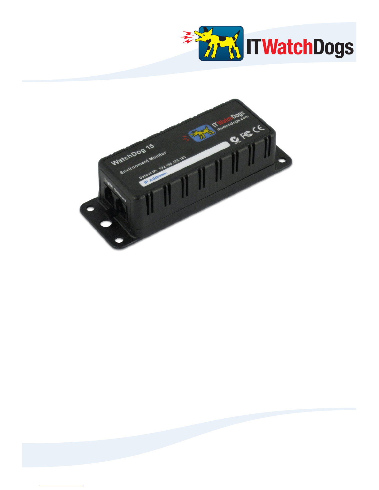
Designed specifically for small-scale applications, the WatchDog-15 provides web-enabled temperature and
humidity monitoring in a compact, low-cost unit with a simple, easy-to-use web interface. Two Digital Sensor
Bus ports provide connections for additional sensors, allowing one WatchDog-15 unit to monitor conditions at
multiple locations within a room. This makes the WatchDog-15 ideal for applications where space is at a
premium, such as small-office server closets, remote telecommunications-equipment sites, or climate-controlled
storage facilities.
The WatchDog-15 comes in two models: The standard “WatchDog-15” model, and the enhanced
“WatchDog-15P” model which includes Power-over-Ethernet (PoE) capability. Aside from the PoE option, both
models function identically, so in general the term “WatchDog-15” or “monitoring unit” will refer generically to
both models in this manual. If it is necessary to point out behavior or information which only applies to a specific
model, such model-specific information (and the model it applies to) will be highlighted in grey.
In this introductory section, you will find illustrations of the WatchDog-15 and its side-panel connections,
along with brief explanations of the unit’s various features and a summary of its specifications.
NOTE: The information provided in the following sections applies to WatchDog-15 units
running at least firmware version v1.4.2. Earlier firmware versions may not have all of the
capabilities described, while later versions may have additional capabilities not included in
this version of the manual. If in doubt, please consult our web site for change-logs, manual
updates, or errata sheets which may apply to your particular model and firmware revision.
WatchDog-15 User Manual rev. A1.02 – Sept.24, 2012
[ 3 ]
Unpacking your WatchDog-15:
When you first open up the box your WatchDog-15 came in, you should find the following items. (Note that
the actual appearance of the devices you received may vary slightly from the sample illustrations shown here.)
WatchDog-15
WatchDog-15
Default IP: 192.168.123.123
IP Address:
Dogs
IT
+6VDC power supply
• Input voltage range: 100 ~ 240VAC, 50/60Hz
• Output voltage: +6VDC, 2A (max.)
• Operating temperature range: 0 – 40°C / 32 – 104°F (typ.)
This power supply is capable of worldwide-voltage (120~240VAC, 50/60Hz) operation, and connects to the
WatchDog-15 via a standard 2.1mm center-positive DC barrel plug.
WARNING: Using any DC power supply other than the model(s) supplied or approved by ITWatchDogs
may damage your WatchDog-15 and void your warranty! If the standard +6VDC wall transformer-style power
supply is not suitable for your application, please contact ITWatchDogs’ sales & service department to discuss
possible alternatives.
The standard +6VDC power supply normally supplied with the WatchDog-15 comes with a U.S.-style
(NEMA 5-15, ungrounded) plug. Power supplies with a U.K.-style (BS 1363) plug, or with a “universal” kit of
interchangeable U.S. / U.K. / European (CEE 7/4) / Australian (AS 3112) plugs, are available as an option.
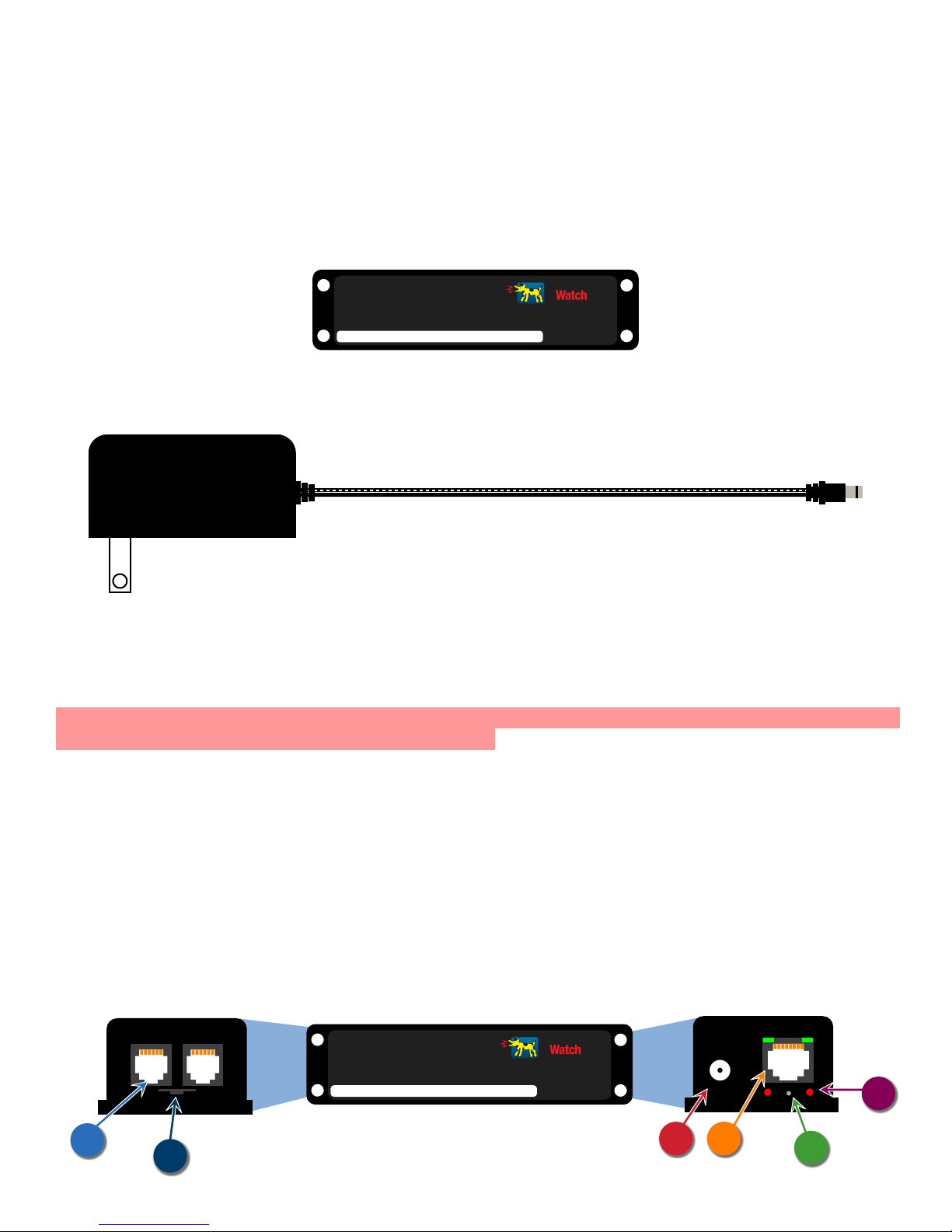
Below is a quick overview of the physical connections and indicators on the side panels of the WatchDog-15.
(Note: the sample diagrams shown below have been simplified for clarity, and are not to scale; the actual physical
appearance of the unit may vary.)
DIGITAL SENSORS
A
B
WatchDog-15 User Manual rev. A1.02 – Sept.24, 2012
WatchDog-15
Default IP: 192.168.123.123
IP Address:
[ 4 ]
ETHERNET
Dogs
IT
C
6VDC
D
RESET
F
E

Digital Sensor jacks:
A
These 6P6C modular jacks allow you to connect one or more Digital Bus-type sensors to the WatchDog-15.
Note that while only two physical jacks are provided, the WatchDog-15 can support up to four external sensors
via the use of a passive port splitter to multiply the number of physical connection points. (This will be illustrated
in the sample hookup diagrams later in this section.)
The Digital Bus-type sensors used by the WatchDog-15 are the same as those used by the WeatherGoose
series. The WatchDog-15 supports all of the existing single-function sensors, such as RT-series temperature
sensors, RTAFHD3 temperature/airflow/humidity probes, and the RPM-X2 Remote Power Manager. Complex
multifunction accessories such as the IOE I/O Expander, however, are not supported due to their large datastorage requirements; generally, these devices are better suited to the WeatherGoose-II series.
Also note that the WatchDog-15 does not support discontinued “legacy” devices such as the RTAF2 or
RTAFH2 airflow probes, or the PowerEgg series of AC power monitors.
NOTE: the WatchDog-15 has a maximum limit of 600 ft. of total cable length on the Digital Sensor Bus; i.e.
you can have a single external sensor 600ft away from the unit, or two sensors with 300 ft. cables, or two at 100
ft. plus two at 200ft., or any other combination of cable lengths as long as (A) the number of sensors does not
exceed four, and (B) the cable lengths do not add up to more than 600 ft. total.
Temperature/Humidity sensor tab:
B
The WatchDog-15’s built-in temperature and humidity sensors are mounted here, protected by a metal cage
around the circuit-board tab. The unit should be mounted in such a way that this tab is exposed to the environment
to be monitored.
DC power jack:
C
The +6VDC power supply’s 2.1mm, center-positive barrel plug fits into this socket to provide power to the
WatchDog-15.
Ethernet jack:
D
This jack features two green LEDs indicating the connection status. The LED on the right indicates
“link/active”; it will light up solidly when the unit is physically connected to the network (“link”), and blink when
the unit is being accessed (“active”). The left-hand LED indicates the link speed; when lit, it indicates a 100Mbit
connection.
RESET pinhole:
E
Holding down the switch behind this pinhole for approximately 15 seconds, until both the Active and Idle
LEDs light up solidly (no blinking pattern), will reset the unit’s IP address to the factory default of
192.168.123.123. It will also clear any User Accounts username/password settings on the Config tab, allowing
you to regain access to the unit even if you’ve forgotten your passwords or accidentally misconfigured the unit.
If this pinhole switch is held down for at least 5 seconds while powering up the unit, it will completely erase
all settings and return the WatchDog-15 to its “out-of-the-box” factory configuration.
Active / Idle LEDs:
F
Located below the Ethernet jack on either side of the RESET pinhole, these serve as indicators that the
WatchDog-15 is operating properly and communicating with the sensor-bus controller and external sensors (if
any). The “Idle” LED will normally blink approximately once a second while the WatchDog-15 is operating,
while the “Active” LED will light up when the main CPU is actively exchanging data with the internal or external
sensors via the bus controller.
WatchDog-15 User Manual rev. A1.02 – Sept.24, 2012
[ 5 ]

Specifications
• Power requirements – WatchDog-15 unit: +6VDC
140mA (0.84W) typ. (no external sensors,)
350mA (2.1W) max. (4x RTAFHD3 sensors)
• Power requirements – AC Power Adapter: 100 ~ 240VAC, 50/60Hz
(included w/unit)
• Power requirements – Power-over-Ethernet: IEEE 802.3af-compliant (48VDC, 1W typ.)
(WatchDog-15P model only)
• Inputs: 2 Digital Sensor Bus connections (2x 6P6C modular jacks)
• Log-Data Capacity: 1Mb (1024Kb)
• Log-Data Rate: (built-in sensors only*): 20Kb/day (approx.)
• Maximum Digital Sensor Bus cable length: 600ft (182m)
• Operating Temperature Range: –20° ~ +85°C (–4°F ~ +185°F)
†
• Supplied Accessories: (1x) AC Power Adapter, 100~240VAC in, +6VDC out
*
Remote Digital Bus sensors will require an additional 3 ~ 12Kb per day, approximately, depending on the sensor type.
†
Note: typical operating range of the included AC power supply is 0 – 40°C (32 – 104°F). For operation outside of this
temperature range, ITWatchDogs recommends using either Power-over-Ethernet, or using a power supply designed specifically
to operate at extended temperature ranges instead of the included power supply.
WatchDog-15 User Manual rev. A1.02 – Sept.24, 2012
[ 6 ]

Hooking up the WatchDog-15
Once you have unpacked the WatchDog-15 and verified that all of the accessories are in the box, the next step
is to mount the unit in an appropriate location and connect it to your network. The following sections will provide
illustrated examples of how to:
• Connect the external power supply
• Connect the unit to your network via the Ethernet jack
• Connect external Digital Sensor Bus sensors to the sensor jacks
WatchDog-15 User Manual rev. A1.02 – Sept.24, 2012
[ 7 ]
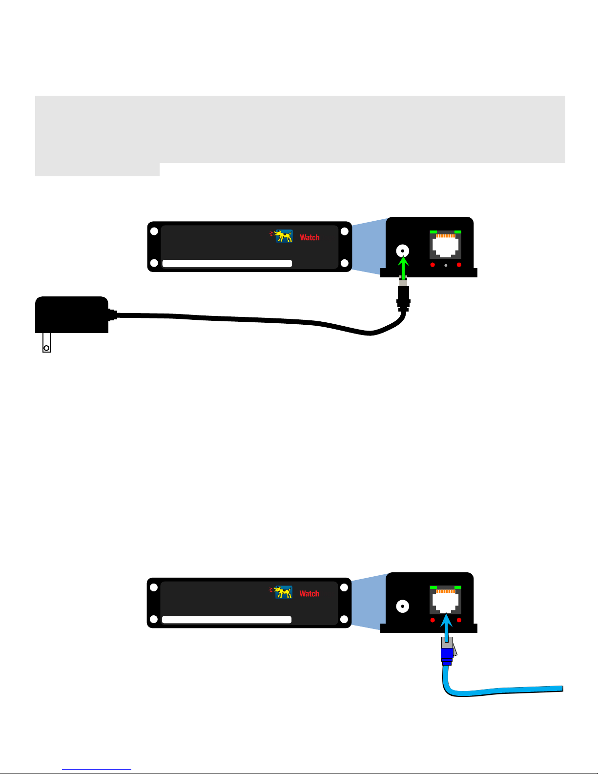
Connecting the external power supply:
The 6VDC power supply’s barrel-plug connector fits into the matching socket, marked “6VDC”, on the
WatchDog-15 as shown below.
►Note:evenifyoupurchasedthePoweroverEthernetcapableWatchDog15Pmodel,andintendtousethePoE
feature to power the unit instead, it may still be necessary to connect the 6VDC power supply while performing
the initial setup and configuration, as the built-in Ethernet ports on most desktop and laptop PCs are generally not
equipped to power external devices via PoE. The WatchDog-15 contains internal protection circuitry to prevent
both power-supply sources from getting cross-connected if both PoE power and the 6VDC power supply are
connected simultaneously.
ETHERNET
WatchDog-15
Default IP: 192.168.123.123
IP Address:
Dogs
IT
6VDC
RESET
Connecting the Ethernet network cable:
Connecting the WatchDog-15 to your network is as simple as plugging a standard Ethernet cable into the
Ethernet jack, as shown here. If the connection is successful (and the WatchDog-15 has power, of course), the
right-hand LED (“link/data”) will illuminate. The “link/data” LED will also blink when the unit is actively
transferring data across the network connection.
The left-hand LED (“speed”) illuminates whenever the unit is connected to a 100Mbit network connection.
If the network connection is only 10Mbit-capable, the “speed” LED will remain unlit.
ETHERNET
WatchDog-15
Default IP: 192.168.123.123
IP Address:
Dogs
IT
6VDC
RESET
WatchDog-15 User Manual rev. A1.02 – Sept.24, 2012
[ 8 ]
 Loading...