

ItWatchDogs APD-G05 Installation & User Manual

APD-G05
GSM Auto-Dialer
installation & user guide
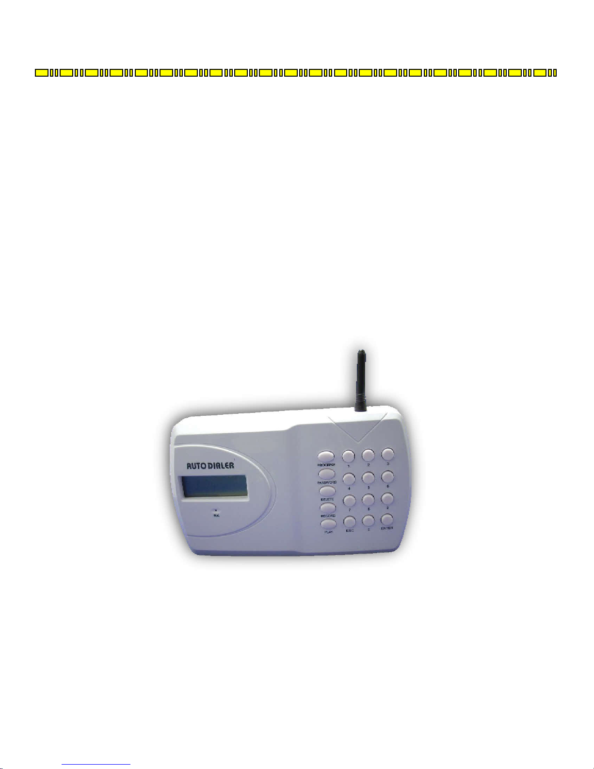
APD-G05 GSM autodialer
While the WeatherGoose monitor series provides IT administrators and facilities managers with a powerful
combination of e-mail and SNMP-based alerts – what happens if your network connections go down and the
messages can’t be sent? Models equipped with dry-contact relays, such as the RelayGoose-II, can even trigger
alarm lights or sirens via the relay outputs – but what if there’s no one around to hear or see them?
The APD-G05 GSM autodialer provides another option. When combined with an ITWatchDogs monitoring
unit equipped with output relays, such as a RelayGoose-II, the APD-G05 can be programmed to call up to nine
different phone numbers and play a pre-recorded message to each person who answers, until one of them
acknowledges the message by pressing the * or # key on their phone, whenever it is triggered by the monitoring
unit’s output relays. The unit can also be programmed to send SMS messages rather than voice, can play one of
two different messages, depending on which trigger input is activated, and can call certain numbers for one trigger
vs. another. It also has a built-in audible alarm, is able to dial out even while running on battery power, and can
be programmed to send out a periodic “test” message to verify that the unit is operating properly.
APD-G05 GSM autodialer
Your APD-G05 GSM autodialer should have come with the following items included in the box:
Ÿ (1) APD-G05 Autodialer
Ÿ (1) 7.2V NiMH battery pack (found inside the battery compartment)
Ÿ (1) 12Vdc power supply
Ÿ (2) drywall anchors and matching screws.
In addition to the items in the kit, to install the APD-G05, you will need (at minimum):
Ÿ an activated SIM card (the unit can use both monthly-contract and prepaid-account cards)
Ÿ at least one length of 2-conductor alarm wire, to connect the APD-G05 to the dry-contact relay terminals on
the relay outputs.
Ÿ appropriate tools (Philips and flat-head screwdrivers, drill, ruler, stud finder, etc.) to mount the unit on the
wall and to connect the wires to the terminal block
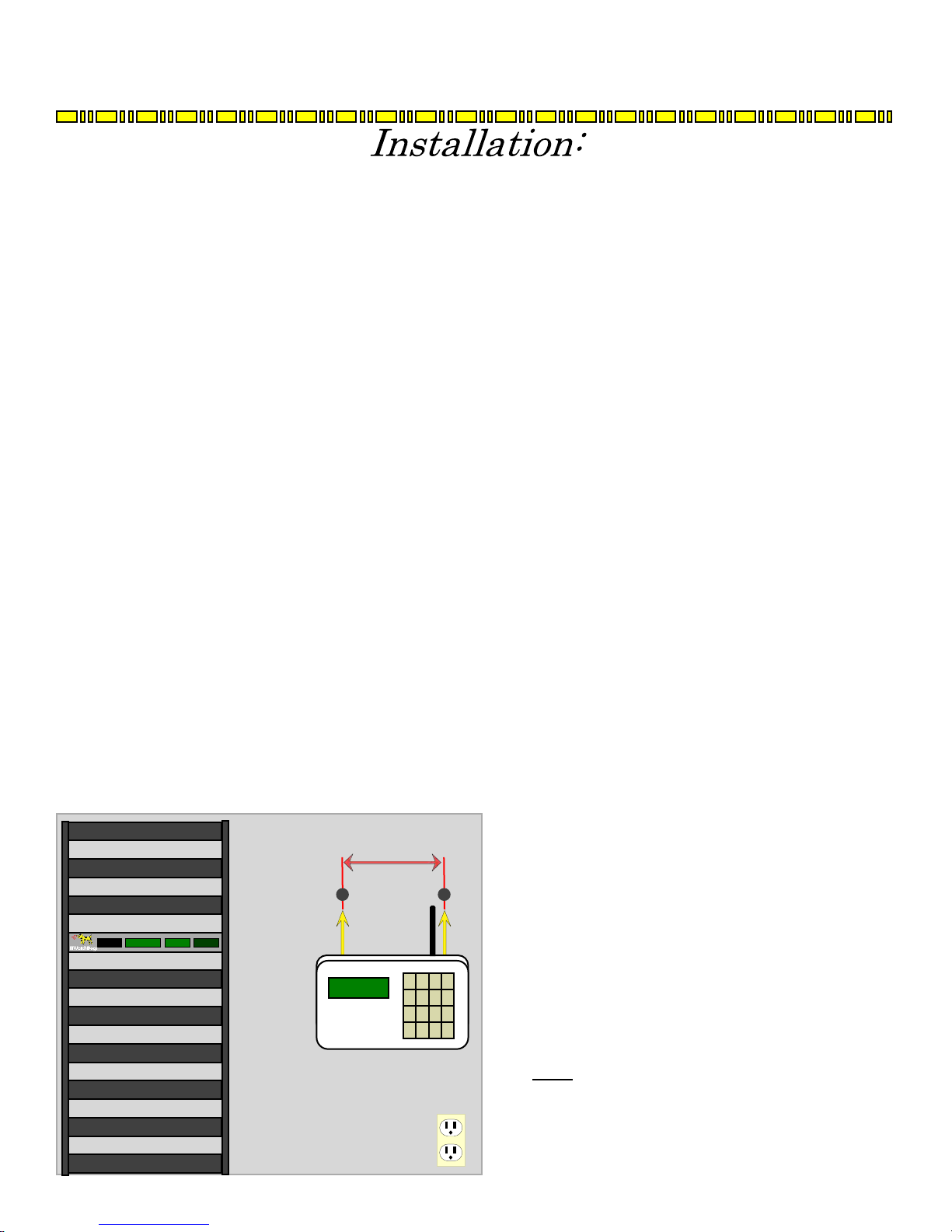
Before you proceed, make sure you’ve chosen an appropriate spot to mount the autodialer; ideally, it should
be located conveniently near an AC power socket, high enough on the wall to be easily operated, in an area where
the unit can get good cell-phone reception. Don’t worry too much about the distance between the autodialer and
the monitoring unit; since the trigger is just a dry-contact relay signal, the trigger signal is essentially immune to
interference from induced EM or RF noise, so the wiring between the autodialer and the monitoring unit can be
dozens, or even hundreds of feet if necessary. (Just make sure the wiring is routed such that no one can trip over
it, and that it can’t get crushed or damaged by equipment rolling over it!)
When choosing a spot for mounting, make sure that there is no electrical wiring or plumbing running behind
the wall in the spot where you intend to drill holes for the drywall anchors. You should also check the cell-phone
signal reception in that spot, by holding your own cell phone up against the wall in the intended mounting space
to see how many “bars” you get; if your cell phone’s reception is poor, then the APD-G05’s reception will also
be poor, and the unit may not work reliably in that location.
160mm
An example of mounting the APD-G05 GSM autodialer unit to
the wall is shown here. The mounting holes should be drilled
160mm apart, using a drill bit just slightly smaller than the
diameter of the drywall anchors; push the anchors into the
holes, then use a philips-head screwdriver to screw the included
fixing screws into the anchors. Make sure you leave about
2~3mm of the screw body protruding from the anchor, so that
the APD-G05 can be hung onto the screw heads.
Also, be sure to make all of the necessary electrical
connections, including connecting the 7.2V NiMH battery
pack, before hanging the unit on the wall.
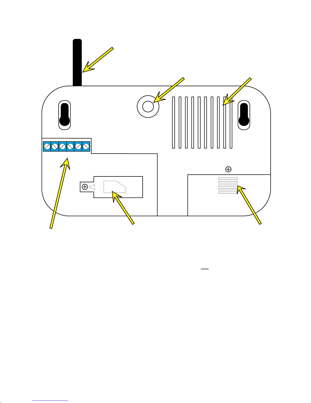
Before you mount the APD-G05 to the wall, turn it over so that you are looking at the back of the unit:
ANTENNA
TAMP TR2 TR1 0V 12V+
ANTI-TAMPER SWITCH
SPEAKER
SIM CARD COMPARTMENT
TERMINAL BLOCK
BACKUP BATTERY
COMPARTMENT
Both the backup-battery and SIM card compartments are secured with a small Philips-head screw. There is
also a raised ridge on the battery-compartment door to provide some friction-lock, so be careful when removing
or replacing the cover. For now, go ahead and remove the cover, but do not connect the battery pack just yet.
Instead, remove the pack and set it aside along with the cover and locking screw.
In addition to the battery pack and connector, you will find a small switch marked “NORMAL / ERASE”
Make sure this switch is in the “NORMAL” position.
To hook up the trigger and anti-tampering signals from the monitoring unit’s relay outputs to the APD-G05
autodialer, you will need at least one length of 2-conductor wire – while we recommend using 2-conductor
alarm-panel wire such as Coleman Cable part# 511014501, Belden Wire & Cable part# 82442 8771000, or
equivalent, any plain old 22 AWG copper wiring will suffice. Examples of these connections will be shown on
the following pages, along with instructions on how to install the SIM card, backup battery, and power supply.

Installing the SIM card:
The first thing to do, even before connecting the power supply or trigger wiring, is to install the SIM card.
The APD-G05 can accept either monthly-contract or pre-paid (“pay-as-you-go”) SIM cards and accounts, so the
choice of cell-phone carrier and service is up to you. (Note that if a pre-paid SIM is used, we recommend
programming the unit to make periodic “self-test” calls to keep the pre-paid account “live”; see the section on
programming the card for more details.) However, keep in mind that some pre-paid accounts – usually the types
associated with so-called “disposable” phones – may be more difficult to use with the APD-G05 than others; in
particular, if the carrier requires you to use the phone itself to add extra minutes to the SIM card, by placing the
phone into a special “refill mode” and typing in lengthy strings of code numbers, you will not be able to perform
this operation from the APD-G05; instead, you’ll have to remove the SIM card from the unit and put it back into
the phone every time you wish to top up the card.
To insert the SIM card:
1. Remove the locking screw from the SIM card cover and flip the cover open, as shown below, to
expose the SIM card slot and card holder.
2. Slide the SIM card holder back and flip it open to expose the card slot and contacts. Be careful not to
apply too much force to the card holder, or to touch the contacts.
3. Insert the SIM card into the slot, with the card’s contacts facing downwards and the beveled corner at
the top right, as shown.
4. Close the SIM card holder and slide it back into the locked position, then replace the SIM card cover
and its locking screw.
TAMP TR2TR1 0V 12V+
SIM
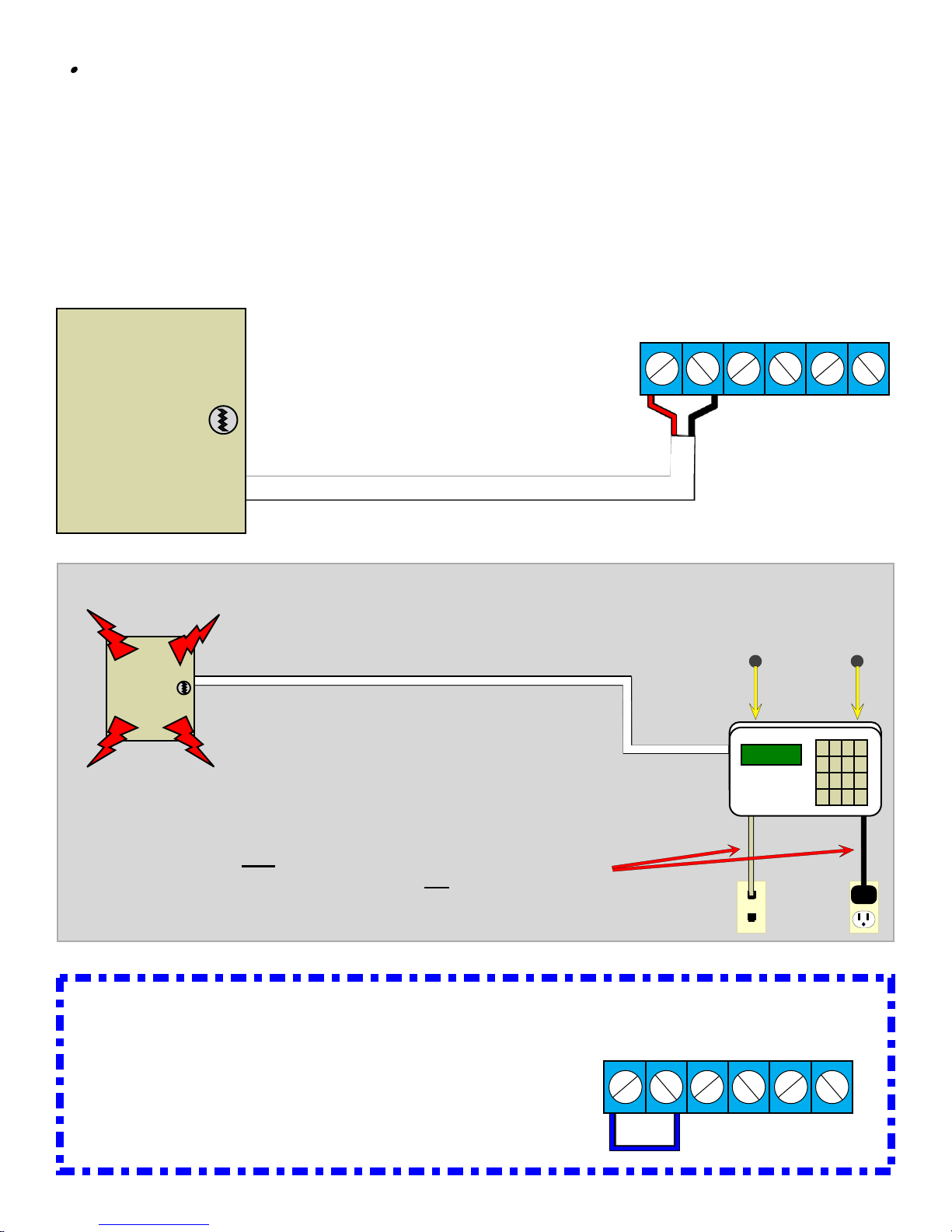
Connecting the anti-tamper switch signal:
The terminals marked TAMP are an NC (Normally-Closed) dry-contact pair, intended for connection to a
building-alarm panel. These contacts will remain closed as long as the unit remains mounted to the wall, keeping
the anti-tamper switch depressed; if anyone attempts to physically tamper with the APD-G05 unit by removing it
from the wall, the anti-tamper switch will be released and the TAMP contact pair will open.
Whether or not you wish to use this function is up to you; if you do, then you should run a length of
2-conductor alarm wire back to your alarm panel. (You could also, of course, run this signal back to one of the
Analog Inputs on the monitoring unit itself, if you wish.) If not, you should jumper the two TAMP terminals
together with a short piece of wire, as shown below.
security
alarm
panel
TAMP TR2TR1 0V 12V+
if the anti-tamper function is desired, run a
2-conductor pair back to your alarm panel,
as shown here, back to any input which is
designed to trigger the security alarm when
contact is broken.
any attempt to tamper with the unit by removing
it from the wall or cutting the alarm wire will set
off the building security alarm
note, however, that this anti-tamper function is
only activated by the spring-loadedswitch on the
back of the unit; it will not activate if the power
supply or phone cord are cut or disconnected.
IMPORTANT NOTE:
if this anti-tamper function is not going to be used,
the TAMP terminals should be jumpered together
with a short piece of wire, as shown here.
TAMP TR2TR1 0V 12V+

Connecting the trigger signals:
The terminals marked TR1 and TR2 are dry-contact triggers which will activate the APD-G05 autodialer.
Each of these inputs functions independantly, allowing you to program the autodialer to dial one of two different
lists of numbers and deliver one of two different recorded messages depending on which input is triggered. Used
in combination with dry-contact relay-equipped ITWatchDogs monitoring unit you could, for example, have the
autodialer call a different set of numbers for a detected water leak on the floor vs. an over-temperature condition
in the room; or, you could use a single autodialer in combination with monitoring units located in different racks
to deliver a different alarm message specific to which rack’s monitoring unit triggered the alarm. Some examples
of these applications will be shown below.
The TR1 and TR2 inputs are triggered when a contact closure grounds the input to 0V, which means that these
inputs should be connected to the NO (Normally Open) contact pairs of the monitoring unit. (For purposes of
illustration, these examples will assume the use of a RelayGoose-II monitoring unit; however, the APD-G05
autodialer can be used with any ITWatchDogs monitoring unit or accessory equipped with appropriate drycontact relay outputs.)
Example #1: One relay output, one trigger input
The simplest application, of course, is using a single trigger input in combination with a single output from a
single monitoring unit (in this example, a RelayGoose-II). Note that since the relay outputs on an ITWatchDogs
monitoring device are true dry-contacts, you will need to bring the 0V (or DC ground) over from the APD-G05
autodialer terminals as well as the TR1 trigger signal, as shown here.
RELAY 1 RELAY 2 RELAY 3
NC NOC
NC NOC
NC NOC
TAMP TR2TR1 0V 12V+
relay 1 de-energized
(no alarm condition)
When wired as shown above, any alarm event associated with RELAY 1 in the RelayGoose-II will energize
the relay, closing the circuit and activating the autodialer sequence. (Instructions on how to set alarms and
associate them with the relays can be found in the Setup Guide & User Manual for your particular model of
monitoring unit or accessory.)
RELAY 1 RELAY 2 RELAY 3
NC NOC
NC NOC
NC NOC
TAMP TR2TR1 0V 12V+
relay 1 energized
(unit is in alarm condition)
completes the circuit and
triggers the autodialer
 Loading...