

Page 1

Access
Control
Panel
DLK642
Installation
Manual
®
DLK642
A C C E S S C O N T R O L P A N E L
Page 2

2 Integrated Technical Vision Ltd http://www.itvsystems.com.ua
Page 3

http://www.itvsystems.com.ua Integrated Technical Vision Ltd 3
This manual covers installation, programming and utilization of DLK642 access
control panel. Read this manual carefully prior to installing and programming the
unit.
Design Change Disclaimer
Information due to design changes and product improvements in this manual is
the subject to change without notice. ITV reserves the right to change the
product design any time, that will subsequently affect the contents of this manual.
ITV assumes no responsibility for any mistakes that can appear in the manual.
The company guarantees that this Installation Manual is up to date and
corresponds with the unit you purchase.
Reproduction Disclaimer
All rights to this document are preserved by Integrated Technical Vision Ltd.
Copying, printing and any other kind of unauthorised reproduction of this
document or a part of it is prohibited.
Trademarks
ITV® is a registed trademark of Integrated Technical Vision Ltd.
Training and technical support
Integrated Technical Vision Ltd provides training in installation, programming and
utilisation of DLK642 access control panel. For detailed information about the
training and discussing of our particular requirements to the unit please contact
our personnel by the phone numbers below.
It is recommended, for the staff intended for sales and installation of DLK642
access control panel, to take instruction courses conducted by ITV company.
Technical support for all products of Integrated Technical Vision Ltd can be
obtained on business time by the following phones:
+380(0)44 248 65 88
+380(0)44 248 65 89
+380(0)44 248 65 90
This support assumes the calls of trained specialists. End users must apply to
their dealers or installers before phoning us. This information is available on our
web site
www.itvsystems.com.ua
Page 4

4 Integrated Technical Vision Ltd http://www.itvsystems.com.ua
Contents
Preface.....................................................................................................................5
Features...................................................................................................................5
Specifications...........................................................................................................5
Terms........................................................................................................................7
What's inside............................................................................................................9
Controls and connections on board........................................................................11
Control Panel Operation.........................................................................................12
Main Mode ............................................................................... .................12
Alarm Mode ............................................................................. .................13
Free Pass Mode ...................................................................... .................14
Blocked Mode ......................................................................... .................14
Mounting..................................................................................................................15
Wiring......................................................................................................................15
Limited Warranty.....................................................................................................20
Page 5

http://www.itvsystems.com.ua Integrated Technical Vision Ltd 5
Preface
DLK642 is an access control panel which operates as totally stand-alone unit with
a fully distributed database. All valid card numbers, time zones and relay pulse
times are loaded to control panel memory. The panel can control access into two
doors with no dependency on a central computer system.
Primary goals of Access Control System are: identification of a person,
confirmation or not confirmation of access, control of movements in a necessary
zone. It can provide time and attendance logging, in addition to usual task of
restricting individuals’ access to certain areas.
All users' access information is captured on a server, where system managers
can retrieve and analyse the information. This data provides recording of staff
movement within an organization, whether it is a small company or a company
that employs thousands.
Features
• Supports all Wiegand reader technologies
• Distributed database for independent operation
• Operates in remote site configurations with dial-up (requires NDC-B052)
• Card, keypad or card and keypad access support
• On-board lithium battery for data storage
• 4-wire RS-485
• 8 supervised programmable inputs
• Tamper alarm
• 2 Form C relays
• Two transistor outputs
• Nonvolatile memory
• Local antipassback function
• Built-in buzzer
Specifications
• Inputs 8 programmable EOL supervised inputs
• Outputs
• Two 5 A @ 24 V relays
• Two open drain outputs 0.5 A @ 24V (with multifuse protection)
• Networking RS485 interface
• EPROM:
• Identificators 1024
• Events 1920
• Time zones up to 250
• Schedules up to 250
• Holidays up to 250
• Input Voltage +10…15 VDC
Features
Page 6

6 Integrated Technical Vision Ltd http://www.itvsystems.com.ua
• Voltage ripple 500 mV @ 12 V
• Power consumption:
• Standby current 80 mA@ 12V
• Maximal current 130 mA@ 12V
• Environmental requirements:
• Operation temperature 0 °С … +55 °С;
• Relative Humidity 80% relative at +35°С;
• Physical dimensions:
• Width 155mm
• Height 95mm
• Depth 32mm
• Weight 0,25 kG
Specifications
Page 7

http://www.itvsystems.com.ua Integrated Technical Vision Ltd 7
Terms
Access point
Access point is a logical concept of the access control system implying control of
passing through a door in one direction. It consists of reader, access control panel
(or its part), door supervision devices (like magnetic sensor, RTE etc.) and door
locking device. For instance, the turnstile with two way passes has two Access
points – one for entrance and the other one for exit, door of this type is called
double-sided door. A door with a reader on one side has only one Access point –
Entry point, and it is called single-sided door.
Antipassback
Antipassback function is implemented in DLK642 access control panel in order to
prevent the situation when user gives his ID to another person after passing into
the premises. If this function is on, DLK642 tracks an ID position – Inside or
Outside the premises. On any attempt to pass in the same direction twice
DLK642 denies access and stores “Access Denied, Antipassback” event into the
Log.
Antipassback function can be set on only in case of the double-sided door control.
Code matching
DLK642 can activate alarm on attempt of a code (or ID) matching. Code matching
is considered when invalid code (or ID) is entered several times succesively. Valid
code entering clears the counter. This function switching on and number of code
entrances are subjects of programming.
Door Contact (DC)
In access control systems various sensors are used to supervise door status
(opened or closed) – magnetic door sensor, sensor of the turnstile rotor position,
inductive sensor of car passing through the road barrier, etc.
Door Contact terminal of DLK642 is intended for connection of these sensors.
Door time
If door sensor is open, corresponding access point goes into alarm. Alarm is not
invoked, if contact is opened during Door Time interval. This interval starts when
access is granted and lasts for the programmed time or terminates on opening
and subsequent closing of door contact.
Downloading
DLK642 is to be downloaded after all parameters setting – modes of inputs,
outputs, access rights and others on PC. During downloading parameters are
rewritten into access control panel. If you change control panel parameters in
your computer, they will not take effect until this parameters are downloaded to
control panel.
PIN (Personal Identification Number)
Some readers have built-in keypad. Keypad may be used for PIN entering. It can
be both self dependant or used as an additional code to ID. When PIN is programmed as additional code, DLK642 waits for PIN entering after ID is read-out.
PIN is associated with ID.
Terms
Page 8

8 Integrated Technical Vision Ltd http://www.itvsystems.com.ua
Proximity Identificator
In access control systems each user has ID (identificator) with unique code.
Proximity IDs may be in shape of plastic card, keytrinket, etc.
Reader
Readers are devices assigned for reading information from IDs and transmitting it to
control panel
There are several types of IDs and readers for them. It is essential that reader and
control panel should use the same interface. DLK642 utilizes Wiegand interface.
RTE (Request to Exit)
To exit from the premises with a single-sided door, a button wired to control panel is
used. This button is called RTE (Request To Exit) button. If someone opens a door
otherwise than pressing RTE button – by re-energising locking device, opening lock
with a key etc., "Door Forced Open" event arises.
RTE button may be used for remote door opening as well.
Schedules
DLK642 is capable to store up to 250 time zones. 250 week schedules can be
combined from these time zones.
Moreover DLK642 can store several “floating” schedules, based on a period
different to a week. The number of such “floating” schedules depends on period
length.
“Several IDs' access
To enter high security premises presence of more than one person may be
required . DLK642 allows to assign up to 15 groups of people with the access
rights. Access is granted only in case when one person from each group is
present. For instance you have the room which can be attended only by
personnel of R&D department escorted with guard. You can form two groups for
this access – group of R&D employees and group of guard. Access is granted if
two IDs from different groups read by panel readers – one belongs to R&D
department employee and the other one – is a guardian.
Time zone
Any interval of time which has the beginning and the end.
Terms
Page 9
http://www.itvsystems.com.ua Integrated Technical Vision Ltd 9
What's inside
General Configuration
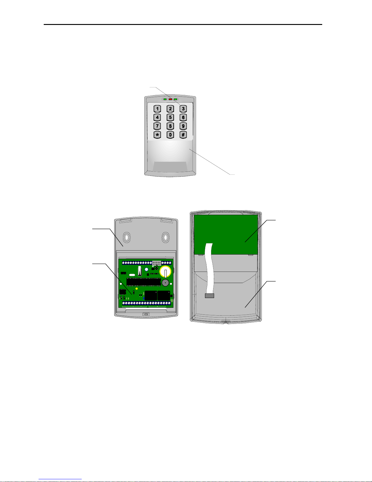
The layout of DLK642 is shown on Diagram1 below.
Figure1. a). General view of DLK642, b) DLK642 with front cover off
1 - LEDs,
2 - built-in reader,
3 - backplate,
4 - panel's PCB,
5 - PCB of the reader,
6 - front cover.
2
a)
1
D1 D0 GN RDZ1 GND + ER BZZ2 GNDZ3Z4 GNDZ5Z6 GND
A+
B- GND + EB Z7 GND Z8 -PW R+ TM NC1 C1 NO1 NC2 C2 NO2 SA BEL
X1
S3
S4
S6
BAT
RST
S8
S9
X3
DLK
642
VL1
X2
X2
S5
3
4
5
6
б)
What's inside
Page 10
10 Integrated Technical Vision Ltd http://www.itvsystems.com.ua
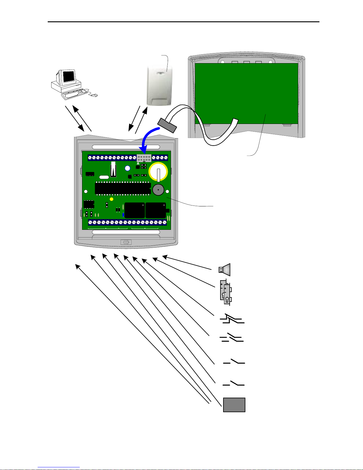
Wiring Configurations
Figure2.Terminals layout.
D1 D0 GN RDZ1 GN D + ER BZZ2 G NDZ3Z4 G N DZ5Z6 G N D
A+
B- GND + EB Z7 GN D Z8 -PW R+ TM N C1 C1 N O1 N C2 C2 N O2 SA B EL
X1
S3
S4
S6
BAT
RST
S8
S9
X3
DLK
64
2
VL1
X2
X2
S5
Panel's PCB
PCB of built-in
reader
Bell
Locks or strikes
PC
RS485
Door Contacts
RTE's button
Free Pass
button
Door Blocking
button
Mains Status
Power Supply +12 В
Battery Status
External reader
What's inside
Page 11
http://www.itvsystems.com.ua Integrated Technical Vision Ltd 11
Controls and connections on board
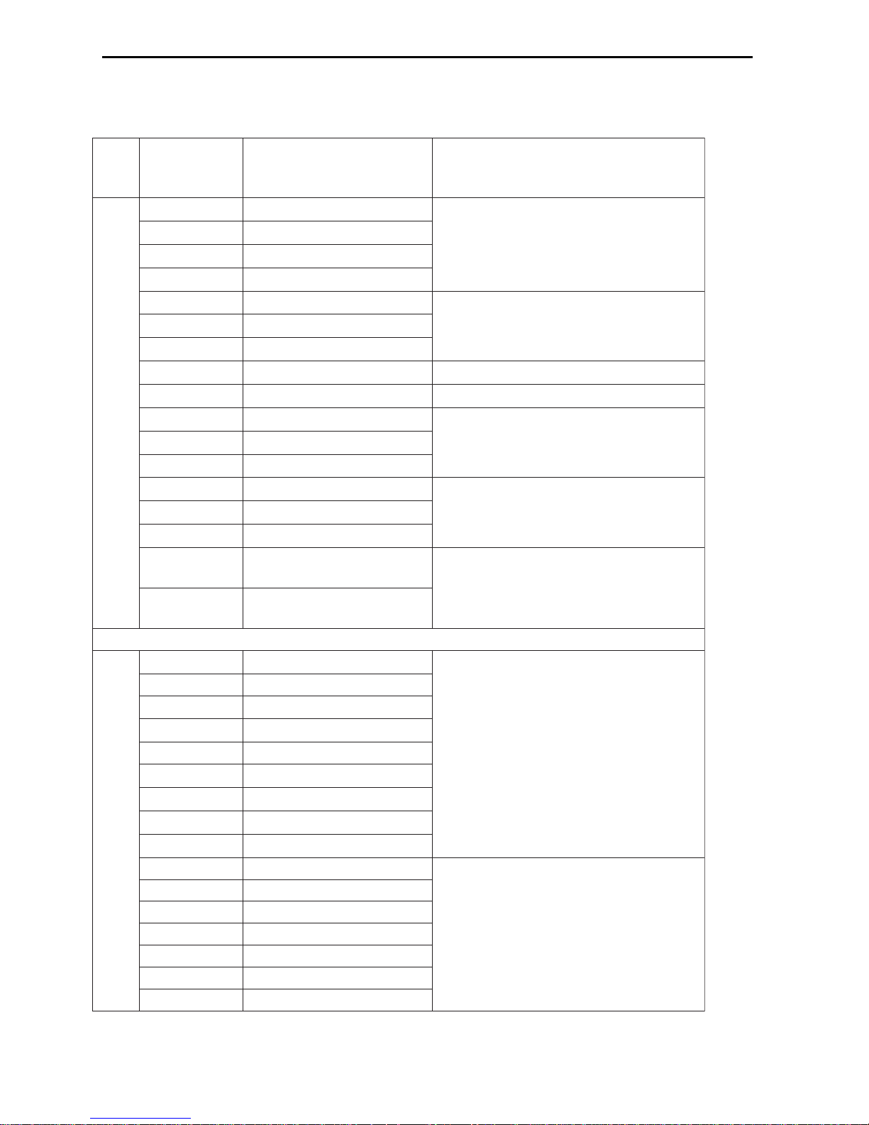
Terminals' assignment
-imreT
lan
kcolb
lanimreTnoitcnuFnoitpircseD
1X
+AA-584SR
enilpord584SR
-BB-584SR
DNGnommoC584-SR
BE+584SR21+
7Z
7enoZ
elbammargorpdesivrepusLOE
noitcennoc8,7stupni
DNG
nommoC
8Z
8enoZ
+RWP-
rewoP
ylppusrewopgnitcennocrofslanimreT
MT
tcatnoCrepmaT)desolcyllamroN(tuptuotcatnocrepmaT
1CN
desolcyllamroN
stcatnoc1yaleR1CnommoC
1ONnepoyllamroN
2CN
desolcyllamroN
stcatnoc2yaleR
2CnommoC
2ON
nepoyllamroN
AS
@V21+tuptuorotsisnarT
A3,0
lanoitucexefonoitcennocroF
secived
LEB
tuptuorotsisnarT ( nepo
A3,0@)niard
2X
6ZZeno 6
noitcennoc'stupniLOE6-1
DNG
DNG
5ZZeno 5
4ZZeno 4
DNGDNG
3ZZeno 3
2ZZeno 2
DNG
nommoC
1Z
1enoZ
DNG
V21-
slanimretnoitcennocredaeR
BE+21+ V
ZB
lortnocrezzuB
1D
ATAD 1
0D
ATAD 0
NG
lortnocDELneerG
DR
lortnocDELdeR
Controls and connections on board
Page 12

12 Integrated Technical Vision Ltd http://www.itvsystems.com.ua
Jumpers and LED
- RST - Reset jumper
- S3, S4, S6 - Jumpers for RS-485 load selection
- S5 - Tamper
- BAT - Real-time clock power switch
- S8, S9 - Reader mode (Wiegand/Special reader) setting jumpers
- VL1 - Live function indicator
Jumper BAT should be shorted before installation and broken during transportation
and storage.
Control Panel Operation
Control panels are supplied unprogrammed. In this state reader LEDs do not light.
VL1 panel yellow LED blinks 5 times per second. Panel does not respond to IDs'
passing and inputs' opening and closing. A panel should be downloaded to start
operation mode with DC Configurator or Golden Gate program.
Yellow LED starts to blink one time per second and switches to the main mode
automatically after successful settings' downloading.
Panel can be turned to the unloaded status only with command from PC, see
programming instruction.
Panel can control two independent access points. Each access point may be in
one of four modes: main mode, alarm, blocked or free pass. Free pass mode has
the highest priority, as panel switches to this mode in case of fire; then blocked,
alarm and main modes follow.
Main Mode
Panel grants or denies access to cardholders in this mode. In Main mode reader's
LEDs blink red.
Access with ID
To access the premises cardholder passes identificator to a reader. If it is valid a
panel grants access, unlocks a door and green LED switches on.
Access with ID and PIN
To access the premises cardholder passes ID to the reader. The panel checks
necessity of PIN entering and if it is necessary, reader starts to blink yellow, that
means PIN entering is awaited. After valid PIN entering door is unlocked, reader's
LED lights green.
Using RTE
To exit out of the premises with a single-sided door, users have to depress (press
& release) Request to Exit button. Reader and panel LEDs light green.
“Several IDs” access
To access the high security premises, bank depot for instance, the presence of
more than one person may be required. At least two people should enter the
depot, for example a board member escorted with a guard. You can program the
panel thus access will be granted after two cards of different groups are passed to
the reader.
Control Panel Operation
Page 13

http://www.itvsystems.com.ua Integrated Technical Vision Ltd 13
Access Denial
Access may be denied for the following reasons (LED lights red):
- Panel is not downloaded (LED does not light or blink)
- ID is not enrolled (red LED and buzzer switch on for a second)
- ID time expired (red LED and buzzer switch on for a second)
- Access is prohibited at the present moment/day (red LED and buzzer switch on for
a second)
- Attempt of repeated access with Antipassback function switched on (red LED and
buzzer switch on for a second)
- Lost or blocked ID is passed (red LED and buzzer switch on for a second)
- The panel is in Alarm mode (red LED lights uninterruptedly)
- The panel is in Blocked mode ( LED blinks red and yellow)
- Attempt of code matching (if the function was switched during programming)
In Alarm mode panel activates outputs assigned for Bell and Alarm. Alarm output
is deactivated when panel switches into a mode different to alarm.
Bell output is deactivated after programmed time.
If access point is in Alarm state it is prohibited to pass through this point. RTE
button unlocks a door.
To switch Alarm mode off pass ID card with “Alarm off” sign or give a command
from PC.
Alarm Mode
In alarm mode reader red LED lights constantly.
Access point switches into Alarm mode for following reasons:
- In case of door ajar
- Attempt of access with lost ID
- If door is opened too long (door time expired)
- In case of attempt of code matching (if switched on during programming).
Access point does not go into alarm mode in case of panel box tampering, alarm
output activates only.
You can forbidd access point change into Alarm mode in case of "Door opened too
long" event. The prohibition can be programmed for each door separately.
In alarm mode panel activates outputs assigned for BELL and ALARM. Alarm
output is deactivated when panel switches into a mode different to alarm mode
and it is recommended to program duration time for BELL output.
If access point is in alarm mode passing through this point is prohibited. RTE
button unlocks the door.
To switch alarm mode off pass ID with “Alarm OFF” sign or switch it off with
command from computer.
Control Panel Operation
Page 14

14 Integrated Technical Vision Ltd http://www.itvsystems.com.ua
Free Pass Mode
Sometimes situations arise when a door should be open for free pass to everyone,
e.g. in case of fire, earth quake or any other disaster. For such cases the panel has
Free Pass mode.
In this mode reader LED blinks green and yellow alternately.
Access point switches into Free Pass mode with PC operator command or if an
input, programmed as “Free Pass”, is violated.
Access point is in Free Pass Mode until this input is open or operator cancels the
mode.
While Access point is in Free Pass mode the locking device is locked and the
panel does not respond to IDs' passing, PIN entry or RTE button pressing.
The control panel allows you assigning of Free Pass function to an input for one
access point A, B or two access points together (A + B).
Blocked Mode
Blocked Mode is intended for use in situations when access to the premises
should be prohibited for everyone, in case of security alarm for instance. When
Access point is in the Blocked mode access is granted only to IDs with “Security
Service” sign. Door cannot be unlocked with RTE button.
During Blocked mode time reader LED blinks red and yellow alternately.
Access point switches into Blocked mode with PC operator command or when
input, programmed as “Blocking” is violated. Access point remains in Blocked
mode while this input is violated or operator cancels the mode.
The control panel allows you assigning of Blocking function to an input for one
access point A, B or two access points together (A + B).
Control Panel Operation
Page 15
http://www.itvsystems.com.ua Integrated Technical Vision Ltd 15
Mounting
Design and view of DLK642 access control panel allow to mount it directly at a door
and use built-in reader and keypad. It should be stationed at access point at a height,
convenient for all users.
While mounted on metal surface, reading range decreases.
Do not mount the panel or lay wires closely to mains power wiring and other
sources of electromagnetic interference.
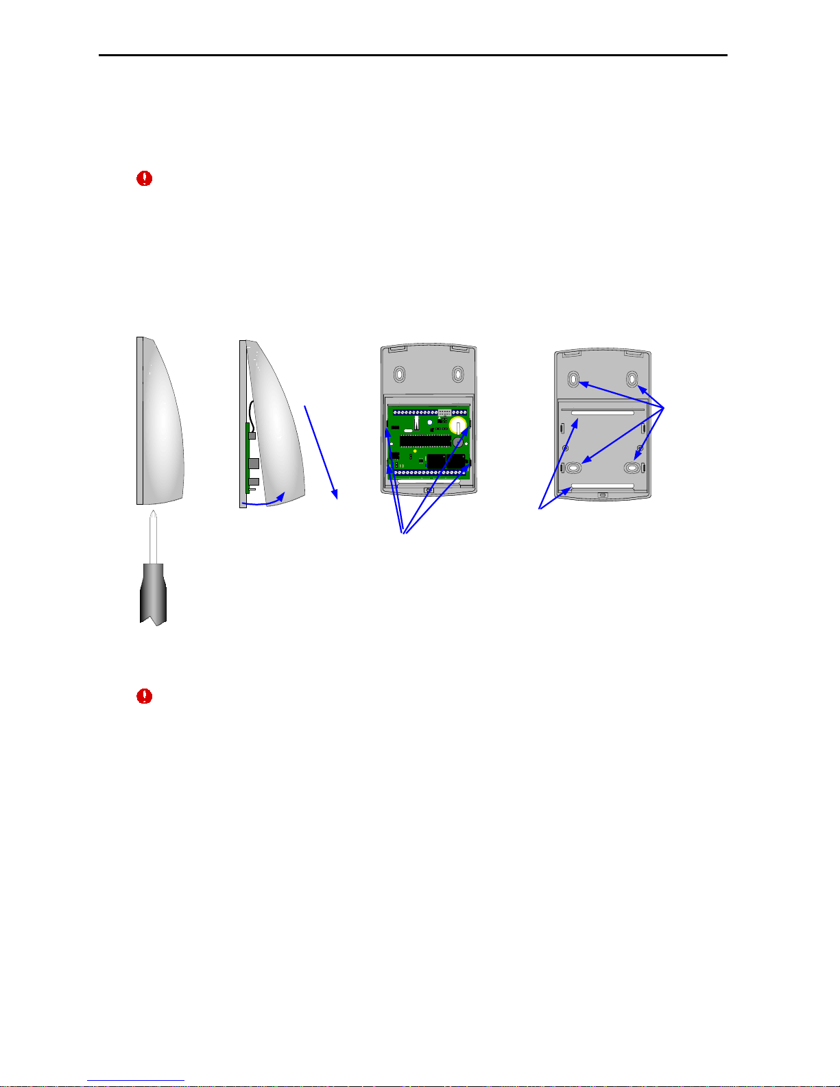
To mount the panel on a wall proceed as follows:
- Release the screw in the lower part of cover (Figure 3a)
- Lift front cover slightly in the bottom part and pull it downwards (Figure 3b)
a) b) c) d)
Figure3. DLK642 mounting specifications.
While istalling the panel set jumper BAT into lower position before programming.
Set it into upper position for a long term storage and trasportation.
Wiring
Connecting readers
DLK642 can control two access points using two readers, one is built-in reader
the other one is external reader. They can be readers produced by ITV Ltd or
other readers with Wiegand interface.
X2 terminal block is intended for access point A (entrance in case of double-sided
door) reader connection. It can be iPN series reader or another one with
Wiegand interface.
X3 terminal is intended for access point B (exit in case of double-sided door)
reader connection.
Reader and controller are to be mounted on wall directly at a door at convenient
height.
5...10мм
Fixing tabs
D1 D0 GN RDZ1 GND + ER BZZ2 GNDZ3Z4 GN DZ5Z6 GND
A+ B- GND +EB Z7 GND Z8 -PWR+
TM N C1
C1 N O1 NC2
C2 N O2 SA BEL
X1
S3
S4
S6
BAT
RST
S8
S9
X3
DLK
64
2
VL1
X2
X2
S5
Wirihg
holes
Fixing holes
Mounting
Page 16
16 Integrated Technical Vision Ltd http://www.itvsystems.com.ua
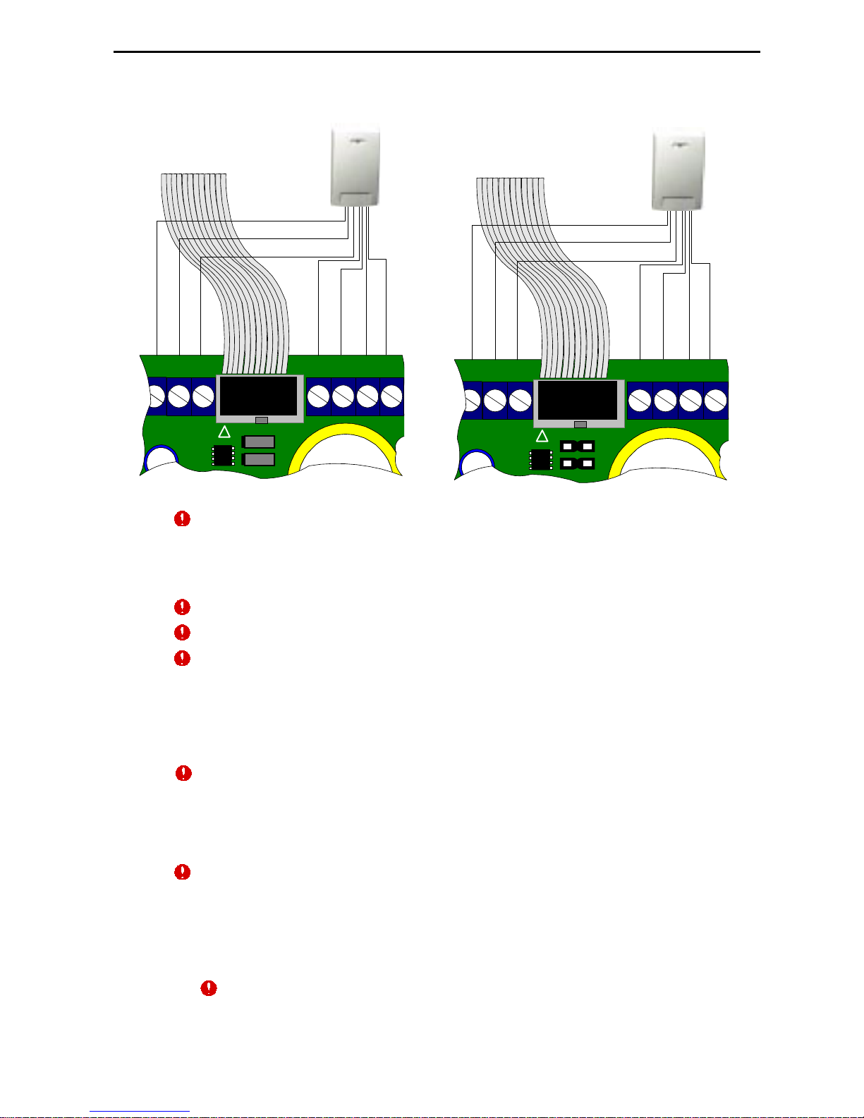
The wiring is shown on Diagram below.
Wires colours can differ in readers of other vendors. Please refer to your reader
installation manual.
External reader connecting cable length can be increased up to 50 meters by
AWG 8x0.22 cable.
During increasing of cable length mind the conductors.
Do not mount the reader on metal surface. It decreases reading distance.
Reader is to be mounted at 50sm minimum distance from controller. Otherwise
reading distance will be decreased.
Inputs wiring
DLK642 has eight EOL inputs. All inputs are programmable - see details in
Golden Gate manual. After reset to factory defaults all inputs become unassigned and not supervised. All inputs supervise shortage and break. EOL usage
is mandatory.
The following input functions are possible:
- door sensor (A, B, A+B)
- RTE button
- door sensor + RTE button
- free pass (A, B, A+B)
- blocking (A, B, A+B)
- state monitoring
Input normal state is from 1,4 kOm up to 3 kOm. Input short circuit is less
than 1,4 kOm and input break is more than 3 kOm.
D1 D0 GN RDGND+ERBZ
S8
S9
X3
X2
white
orange
brown
blue
red
black
green
Built-in reader
connection
cord
Wiegand
reader
D1 D0 GN RDGND+ERBZ
S8
S9
X3
X2
white
green
orange
blue
red
black
yellow
Built-in reader
connection
cord
iPN series
special reader
Wiring
Page 17
http://www.itvsystems.com.ua Integrated Technical Vision Ltd 17
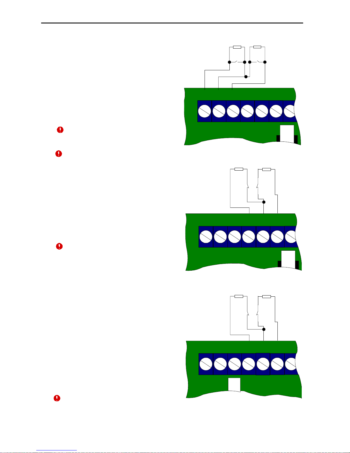
RTE button
Request To Exit (RTE) button is to be
used in case of single-sided door. In this
case door opens on depressing of RTE
button.
RTE button may be used for remote
door opening - for secretary or guard to
open a door, for instance.
On the diagram wiring of normally
opened RTE button is shown. RTE is
wired to Z5 and Z6 terminals.
Usage of deblocking button on electric lock
instead of RTE buton will cause "Door
forced open" event.
It is not recommended to use Z7 and Z8
terminals for RTE button connection.
Door Sensor
Door state (opened or closed) is determined by the state of door sensor. If door
sensor is not connected, the panel is not
able to determine events of door forced
open or unclosed door.
Wiring of normally closed door sensors
to Z3 and Z4 terminals is shown on
wiring diagram.
It is not recommended to use Z7 and Z8
terminals for door sensor connection.
Free Pass and Blocking
An input may be programmed for Free Pass or Blocking.
If input is programmed for Free Pass
DoorA & DoorB, Free Pass Door A or
Free Pass Door B then shortage or
opening of this input unlocks corresponding locking device and personnel can
pass freely through the door.
If input is programmed for Blocking, then
shortage or breaking of this input
discards access rights to all IDs, except
for those with “Security service” mark.
Wiring of normally closed (NC) or
normally open (NO) control panel
contacts to Z1 and Z2 terminals is shown
on wiring diagram.
It is not recommended to use Z7 and Z8
terminals for free pass and blocking iinputs accessing.
Door
Sensor of
access
point A
EOL
resistor
Door
Sensor of
access
pointB
EOL
Resistor
Z2Z3Z4 G N DZ5Z6 G N D
X2
S5
Blocking
wiring
with NC
or NO
contacts
EOL
FreePass
wiring
with NC
or NO
contacts
EOL
Z1Z2 G N DZ3Z4 G N D
X2
S5
RTE
button for
access
point B
RTE button
for access
point A
EOL
resistor
EOL
resistor
Z2Z3Z4 G N DZ5Z6 G N D
X2
S5
Wiring
Page 18
18 Integrated Technical Vision Ltd http://www.itvsystems.com.ua
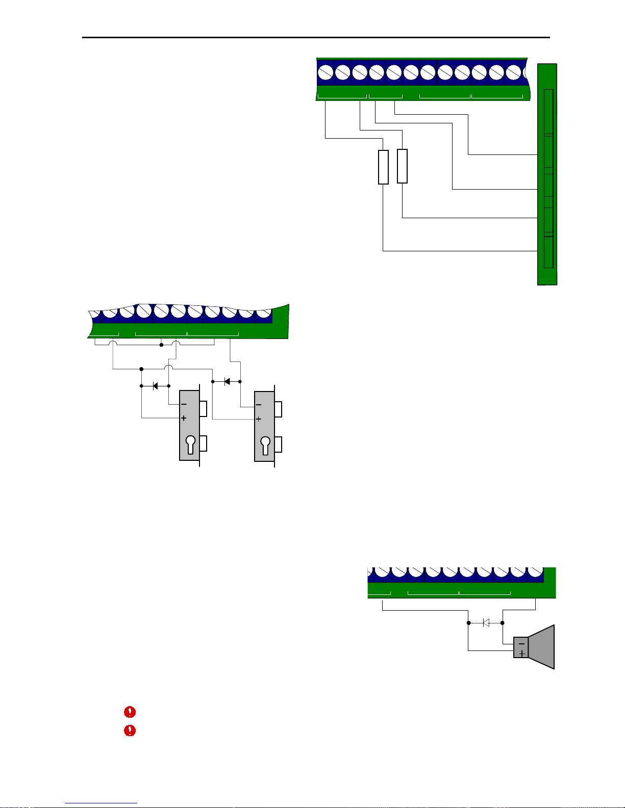
Power supply wiring
It is recommended to use PSU
1,5 power supply with battery
backup, manufactured by ITV
Ltd. This power supply
provides 12V power rated at
1,5A. 4AH or 7AH battery may
be used as well. PSU1,5
power supply has outputs for
signalling of mains power
state and battery state. Wiring
with mains power and battery
state supervising with Z7 and
Z8 terminals is shown on the
picture.
Locking devices
DLK642 has two relay outputs with C form
contacts. Operation time of this outputs may be
programmed from 1 to 255 sec. That allows to
control practically any type of locking device.
Wiring of locking devices is shown on wiring
diagram.
Relay contact rating is 5 Amp @ 24 Volts.
Commutation of inductive load, electric lock for
instance, causes high energy electric impulse
induced through relay contacts. To save
contacts from damage, protect them with diode,
connected in reverse to current supply of the
coil.
Note the fact, that some cheap electric door strikes are not intended for being
energized for prolonged time. Program relay time as short as possible to avoid
door strike coil overheating.
Sirens, Bells and agents
There are two additional programmable
transistor outputs for siren, bell or other
agents control.
Bell output is rated at 300 mA @ 12V and
sinks to the ground.
SA is rated at 300 A @ 12V and sinks to the
ground.
This outputs are electronically protected
against overload. In case of overload
corresponding event is generated.
Some sirens require polarity observing.
Electric bells are often the inductive load for power supply. While connecting bells mind
the warning about the inductive load above.
~220 V power normal
Battery normal
~ AC ~ +12 V
GND PWG ACG
GND
+12 V
DLK642
Power
unit
R
n
2 kOm
Z8 -P W R + TM N C 1 C1 N O1 N C2 C2 N O 2GNDZ7
R
n
2 kOm
Bell
+12 V up to 500 мА
WR+ TM N C1 C1 N O 1 NC2 C2 N O 2 SA B EL
X1
Wiring
Lock of
access
point A
Lock of
access
point B
-PWR+TMNC1 C1 NO1 NC2 C2 NO2 SA BEL
X1
Page 19
http://www.itvsystems.com.ua Integrated Technical Vision Ltd 19
black
yellow
blue
red
A+
B- GN D + EB Z
S3
S4
Z8 -PW R+ TMNC1 C1 NO1 NC2 C2 NO2 S A B EL
X1
LNET
RS485
RS485
RS232
Jumpers
shorted
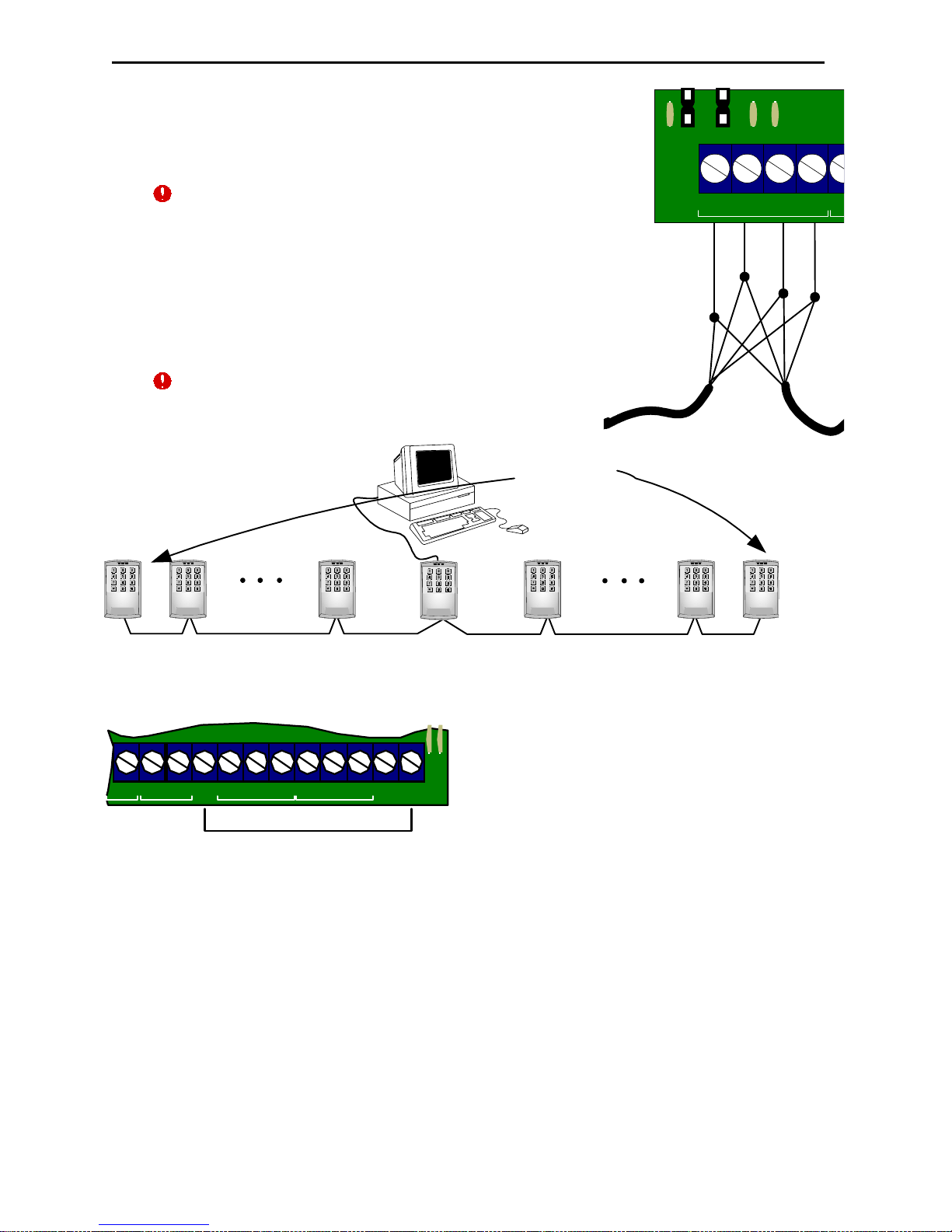
RS-485 Interface
RS-485 Interface is used for networking of the system
components - PC and panels. The range of RS-485 bus
is up to 1200 meters. The number of panels is up to 32.
RS-485 port is protected against overvoltage (60V) and
crosspolarity.
Unshielded four-wire cable may be used for RS-485
wiring. To obtain the maximal range of 1200 meters use
0.4 mm 2 cross section wire. 0.2 mm two-cross section
wire will provide the range of 500 meters .
On the first and last panel in the drop-line short jumpers
S3, S4 and S6 to add the resistive load.
Take care of proper grounding of all panels in the network.
Adress setting
Each panel on RS-485 drop line must have the
unique address from 0 to 31.
To set panel's address proceed as follows:
1. Disconnect feeding of the panel
2. Short terminals TM and BEL
3. Supply feeding. Buzzer will beep several times and current address settings will be
displayed with buzzer beeps and right green LED blinks. The digit is displayed as
number of beeps and blinks with a pause between digits. For example, number 23 is
displayed as:
2 beeps and right green LED blinks, pause, 3 blinks and beeps.
Zero is displayed with continuous sound and LEDs blink. For example, number 04 is
displayed as:
1 continuous sound and right green LED blink then 4 blinks and beeps.
After current address settings displaying, all LEDs blink simultaneously.
4. Enter desired address and press [#] button. Two digits have to be entered
necessarily, for example address 1 is to be entered as [0][1][#].
5. Disconnect feeding of the panel
6. Remove shortage from TM and BEL terminals
Panel is ready for operation with new address.
Wiring
Page 20

20 Integrated Technical Vision Ltd http://www.itvsystems.com.ua
071004
Limited Warranty
Integrated Technical Vision Ltd. warrants that for a period of eighteen months from
the date of purchase, the product shall be free of defect in materials and workmanship under normal use and that in fulfilment of any breach of such warranty,
Integrated Technical Vision Ltd. shall, at its option, repair or replace the defective
equipment upon return of the equipment to its repair depot. This warranty applies
only to defects in parts and workmanship and not damaged incurred in shipping or
handing, or damaged due to causes beyond the control of Integrated Technical
Vision Ltd. such as lightning, excessive voltage, mechanical shock, water damage,
or damage arising out of abuse, alteration or improper application of the equipment.
The foregoing warranty shall apply only to the original buyer, and is and shall be lieu
of any and all other warranties, whether expressed or implied and of all other
obligations or liabilities on the part of Integrated Technical Vision Ltd. This
warranty contains the entire warranty. Integrated Technical Vision Ltd. neither
assumes, nor authorizes any other person purporting to act on its behalf to
modify or to change this warranty, nor to assume for it any warranty or liability
concerning this product.
In no event shall Integrated Technical Vision Ltd. be liable for any direct, indirect
or consequential damages. Loss of anticipated profits, loss of time or any other
losses incurred by the buyer in connection with the purchase, installation or
operation or failure of this product.
Limited Warranty
 Loading...