

Instruction Manual
for
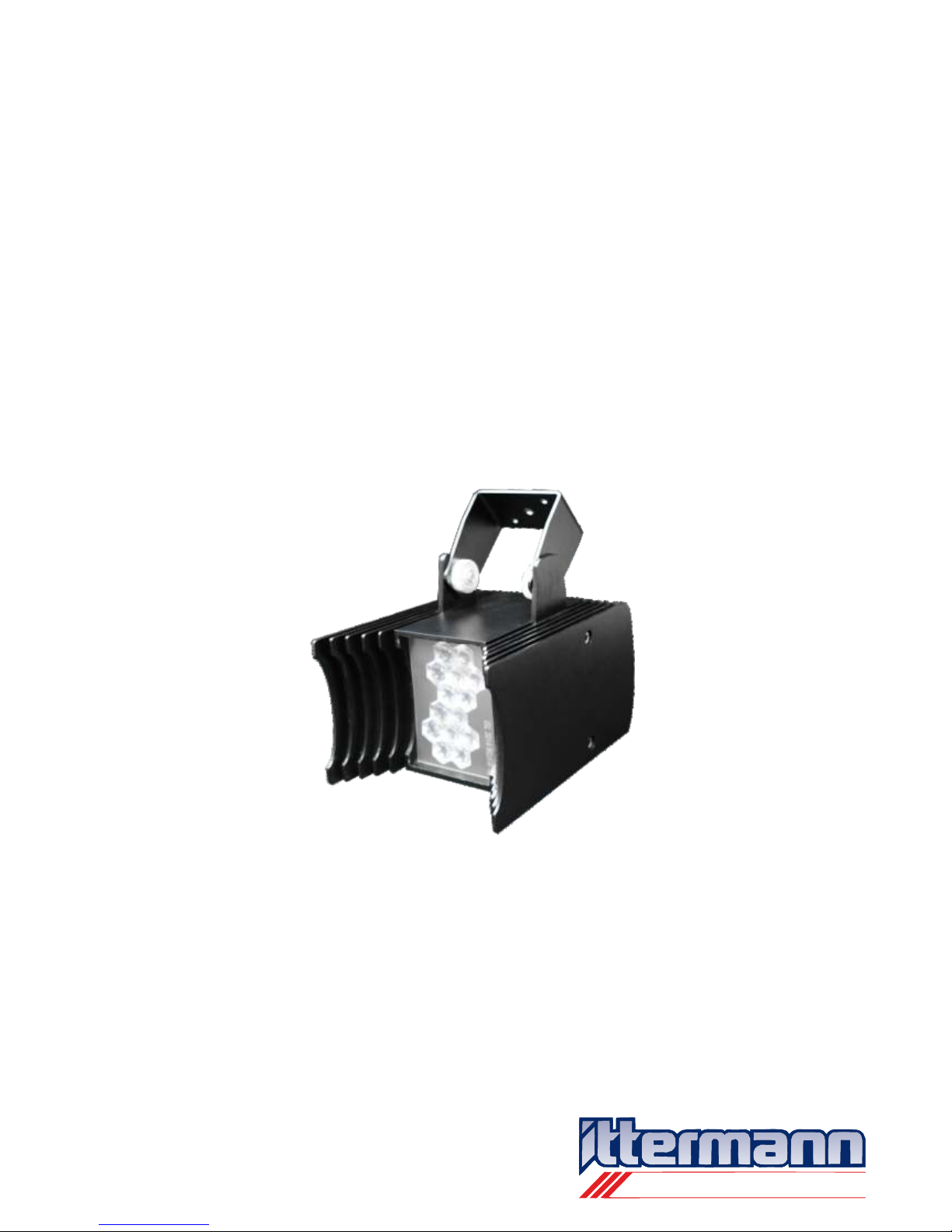
Ittermann SpotLight LED-Flood light
iSL 3014
electronic GmbH
Ittermann electronic GmbH
Köhlergasse 16-18
D - 99842 Ruhla
Phone:
+49 (0)36929
-
75-0
Fax:
+49 (0)36929 - 75-35
Internet:
www.ittermann.de
E-mail:
info@ittermann.de
Instruction Manual iSL 3014
Dated 09th of June 2011

Instruction Manual iSL 3014
Dated 09th of June 2011
Page 2/31
electronic GmbH
Ittermann electronic GmbH
Köhlergasse 16-18
D - 99842 Ruhla
Phone:
+49 (0)36929
-
75-0
Fax:
+49 (0)36929 - 75-35
Internet:
www.ittermann.de
E-mail:
info@ittermann.de
Table of contents
Page
5
5
5
5
7
7
8
9
9
11
11
12
12
13
14
41 General information
1.1 Product description
1.2 Vendor data
1.3 Compliance
1.4 Instruction Manual
1.5 Shipment
2 Terms and Definitions
3 Product Description
3.1 Designated Use
3.2 Design and over all functions
3.3 Type of user
3.4 Technical Data
3.5 Safety notes
4 Supplies
5 Preparation of the product for use
5.1 Preparation before installation
5.2 Installation and electrical connection
5.3 Transition
Technical information and specific terms
4
4
6 Operation
6.1 Preface
6.2 Mode without external control
(Stand-Alone mode)
6.3 Mode with external control
6.3.1 DMX-Mode
6.3.1.1 Technical information and specific terms
6.3.1.2 DMX-Networks with iSL3014
6.3.1.3 Adjustment of addresses
at the DIP-Switches
6.3.1.4 DMX-address from the internal storage
6.3.2 RDM-DMX-Mode
6.3.2.1
6.3.2.2 RDM-DMX-networks with iSL3014
15
15
15
16
16
16
21
22
24
25
25
28

electronic GmbH
Ittermann electronic GmbH
Köhlergasse 16-18
D - 99842 Ruhla
Phone:
+49 (0)36929
-
75-0
Fax:
+49 (0)36929 - 75-35
Internet:
www.ittermann.de
E-mail:
info@ittermann.de
Table of contents
Page
29
29
29
30
30
31
31
A1
A1
A3
A5
A12
A17
B1
7 Cleaning, warranty and troubleshooting by user
7.1 Cleaning and warranty
7.2 Troubleshooting
8 Guarantee
9 List of spare parts
10 Abandonment
11 Subject index
A Appendix
Graphic chart of special programs and
DIP-switch adjustments in Stand-Alone mode
(Description on the example of the iSL3014-RGBW)
A.1 Special programs / Type A (SP / Type A)
A.2 Special programs / Type B (SP / Type B)
A.3 Special programs / Type C (SP / Type C)
A.4 Special programs / Type D (SP / Type D)
A.5 Special programs / Type E (SP / Type E)
B Appendix
Graphic chart of special programs
with DMX- and RDM-DMX mode
(Description example iSL3014-RGBW)
Instruction Manual iSL 3014
Dated 09th of June 2011
Page 3/31

electronic GmbH
Ittermann electronic GmbH
Köhlergasse 16-18
D - 99842 Ruhla
Phone:
+49 (0)36929
-
75-0
Fax:
+49 (0)36929 - 75-35
Internet:
www.ittermann.de
E-mail:
info@ittermann.de
1 General information
1.1 Product description
1.2 Vendor data
Description Place of description
Name of producer: Ittermann Back wall
: iSL 3014 Front
Type: RGBW-12 / -50, Front
RGB-12 / -50,
RGBA-12 / -50,
A-12 / -50,
B-12 / -50,
C-12 / -50,
G-12 / -50,
O-12 / -50,
R-12 / -50,
U-12 / -50,
W27-12 / -50,
W30-12 / -50,
W40-12 / -50,
W50-12 / -50,
W65-12 / -50,
RW-12 / -50,
BW-12 / -50,
RBW-12 / -50
Serial number: Ceiling- or wall
fixing bracket
Compliance: Back wall
Ittermann electronic GmbH
Köhlergasse 16-18
99842 Ruhla
Phone +49 (0)36929 75-0
Fax +49 (0)36929 75-35
E-mail info@ittermann.de
Hompage www.ittermann.de
Series
Instruction Manual iSL 3014
Dated 09th of June 2011
Page 4/31

electronic GmbH
Ittermann electronic GmbH
Köhlergasse 16-18
D - 99842 Ruhla
Phone:
+49 (0)36929
-
75-0
Fax:
+49 (0)36929 - 75-35
Internet:
www.ittermann.de
E-mail:
info@ittermann.de
1.3 Compliance
1.4 Instruction Manual
1.5 Shipment
Certificated standards: - EN 55015:2006 + A1:2007 + A2:2009
- EN 61547:2009
The declaration of compliance of the European Union and the
EMV-audit report for the product Ittermann SpotLight iSL3014
can be requested from the producer.
The instruction manual is part of the product and must be stored with
the product.
The edition number is written on every page of the manual.
The details of the manual are checked continuously. Amendments will
be done with the following manual edition.
Changes can be made without notice.
Illuminant
14 high performance LEDs and applied on a metal core
printed board
Luminous element
of the LED flood light, which works simultaneously as
cooling element
- LED – Flood light Ittermann SpotLight iSL3014 with ceiling- or
wall fixing bracket
- 2
- RJ-45 connection lable, lenght = 0,25 m
- Instruction manual
knurled nuts
optics
Housing
2 Terms and Definitions
Instruction Manual iSL 3014
Dated 09th of June 2011
Page 5/31

electronic GmbH
Ittermann electronic GmbH
Köhlergasse 16-18
D - 99842 Ruhla
Phone:
+49 (0)36929
-
75-0
Fax:
+49 (0)36929 - 75-35
Internet:
www.ittermann.de
E-mail:
info@ittermann.de
Program
The logical sequence of commands or assignments which are
achieved by the internal control system of the LED flood light.
Every function, that means everything what the flood light is able to do,
is based on a program or a part of a program. Which program or which
part of a program is active, depends on exactly defined terms and
conditions. Such terms and conditions might be e.g. operating modes
(see chapter 6.3.2.1 Technical information and specified definitions).
Special program
An autonomous running light-example. Special programs are stored in
the internal memory disk of the LED flood light. Some of the special
programs can be activated by special DIP- switch settings in standalone mode. During DMX- and RDM-DMX-mode all special programs
can be performed.
Type of control
Describes the possibilities of controlling the LED-flood lights
1. Mode without external control
2. Mode with external control
Stand-Alone mode
Type of control mode, which doesn´t need an external control.
With this type of control you can activate different special programs
by using the DIP-switch.
DMX- and RDM-DMX-mode
These are types of control, where the LED-flood lights are controlled
by a Bus-system. When using these mode types you need an external
control system, e.g. a mixing desk. The transfer of information
between external control system and LED-flood light is done by
DMX- or RDM-DMX-protocols.
Instruction Manual iSL 3014
Dated 09th of June 2011
Page 6/31

electronic GmbH
Ittermann electronic GmbH
Köhlergasse 16-18
D - 99842 Ruhla
Phone:
+49 (0)36929
-
75-0
Fax:
+49 (0)36929 - 75-35
Internet:
www.ittermann.de
E-mail:
info@ittermann.de
DMX – protocol (DMX = Digital Multiplex)
Is a standardized digital controlling protocol used in stage- and event
technology which controls dimmer, “intelligent” flood lights and effect
DMX has been standardized by the USITT (“USITT DMX512”,
“USITT DMX512/1990”) followed by DIN 56930-2 in 2000 and
ANSI E1.11 (known as DMX512A) in November 2004.
The data stream of DMX protocols always flow in one direction: from
the external control system to the end unit in use.
RDM- protocol (RDM = Remote Device Management)
Is an extension of the DMX – protocol. It allows a bi-directional
communication between external control system and end unit, which
means the data stream flows in two directions.
With RDM the operating comfort increases considerably. E.g. reprogramming of addresses, diagnose of mistakes and transferring
other important information.
The protocol is defined in the “American National Standard
E1.20 – 2006, Entertainment Technology, RDM Remote Device
Management over DMX512 Networks”, published by the
Entertainment Services and Technology Association (ESTA).
The LED flood light Ittermann SpotLight of the serie iSL3014 has been
designed for in-room use but not for use in humid rooms, e.g. saunas
or bath-rooms.
LED flood lights with small angle of radiation are suitable for
punctual accentuation of objects. LED flood lights with a wide angle of
radiation optics are suitable for the illumination of rooms.
The flood lights can be fixed at walls and ceilings.
Notes for installation: see chapter 5 Preparation of the product
for use”
equipment.
optics
3 Product Description
3.1 Designated Use
Instruction Manual iSL 3014
Dated 09th of June 2011
Page 7/31
i
electronic GmbH
Ittermann electronic GmbH
Köhlergasse 16-18
D - 99842 Ruhla
Phone:
+49 (0)36929
-
75-0
Fax:
+49 (0)36929 - 75-35
Internet:
www.ittermann.de
E-mail:
info@ittermann.de
3.2 Design and over all functions
The LED flood light Ittermann SpotLight of the serie iSL3014 consists
of 14 high performance LEDs, which work with co-current flow. The
angle of radiation depends on the attached optics.
Illuminants and lenses of the LED flood light varies from
type to type, see chapter 3.4 Technical data
The active thermic management caters for a high effectiveness of light
and a long life of the LEDs.
By using the DIP-switches at the back of the light you can choose the
types of control.
see chapter 6 Operation for detailed description
for RJ-45 plug connection, please look at chapter
3.4 Technical data
Instruction Manual iSL 3014
Dated 09th of June 2011
Page 8/31
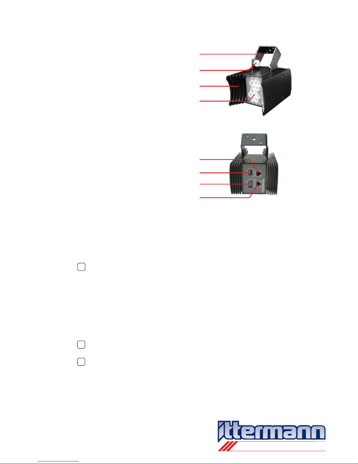
Back view
i
i
i
Front with light exit
IN:
OUT:
DIP-switch 1 (SW1)
DIP-switch 2 (SW2)
RDM-DMX und Power
RDM-DMX und Power
Luminous element
Knurled nuts
Ceiling- or wall
fixing bracket
iSL 3014 RGBW-12ds
RGBW
50
12
ws
sw
si
ds
RGB
RGBA
R
G
B
U
C
A
O
W27
W30
W40
W50
W65
RW
BW
RBW
Serial identification
14
= red, green, blue, white
= 2x25° optic
= 2x6° optic
= housing colour: white
= housing colour: black
= housing colour: silver
= housing colour: dark silver
= red, green, blue
= red, green, blue, amber
= red
= green
= blue
= royal blue
= cyan
= amber
= red-orange
= white, 2700 K (warm white)
= white, 3000 K (warm white)
= white, 4000 K (neutral white)
= white, 5000 K (cold white)
= white, 6500 K (cold white)
= red, white (4000 K)
= blue, white (4000 K)
= red, blue, white (4000 K)
= 14 high performance LEDs
electronic GmbH
Ittermann electronic GmbH
Köhlergasse 16-18
D - 99842 Ruhla
Phone:
+49 (0)36929
-
75-0
Fax:
+49 (0)36929 - 75-35
Internet:
www.ittermann.de
E-mail:
info@ittermann.de
3.3 Type of user
3.4 Technical Data
Mode without external control (Stand-Alone mode)
The usage does not require any special knowledge.
Mode with an external control
Special knowledge necessary.
Instruction Manual iSL 3014
Dated 09th of June 2011
Page 9/31

electronic GmbH
Ittermann electronic GmbH
Köhlergasse 16-18
D - 99842 Ruhla
Phone:
+49 (0)36929
-
75-0
Fax:
+49 (0)36929 - 75-35
Internet:
www.ittermann.de
E-mail:
info@ittermann.de
Voltage: DC 24 V bis 48 V
Power input: app. 50 W
Depends on the used LEDs
Luminous intensity: Depends on the used LEDs and optics
Average life: Ø min. 60.000 hours
Ambient temperature: -20 … +40 °C
Degree of protection: IP20
RJ-45 plug configuration: 1, 3, 7 = Power +
2, 6, 8 = Power –
4 = Data – (B)
5 = Data + (A)
Type of control: - without external control
(Stand-Alone mode)
- with external control
(DMX- and RDM-DMX mode)
Dimming: 256 steps (8 Bit)
Colour mixing: 256 steps per colour (8 Bit per colour)
Programs: 31 internal special programs
17 of them are performable in
Stand-Alone mode
Dimensions: 110 x 113 x 150 mm (wide x hight x
depth, without fixing brackets)
Weight: 1,4 kg
Housing: aluminium with powder coating
Housing colous: - light silver (metallic)
- dark silver (metallic)
- white (RAL9003, soft, fine structure)
- black (RAL9005, soft, fine structure)
Changes of design and technical amendments can be made without
notice by the producer any time.
Instruction Manual iSL 3014
Dated 09th of June 2011
Page 10/31

electronic GmbH
Ittermann electronic GmbH
Köhlergasse 16-18
D - 99842 Ruhla
Phone:
+49 (0)36929
-
75-0
Fax:
+49 (0)36929 - 75-35
Internet:
www.ittermann.de
E-mail:
info@ittermann.de
3.5 Safety notes
4. Supplies
The instruction manual is part of the product and must be stored with
the product.
In case of disregard the instruction manual damages of the product,
fire or other dangers might occur.
Before installation and using the product, please read the instruction
manual completely.
The product is not a toy. Please take care that children have no
access to it.
Please don´t insert anything into the housing.
Don´t look into the lights directly when they are switched on. LEDs are
very bright and might cause retina damages.
The related supplies have been especially developed and tested for
this product. The producer therefore recommends to make use of
these supplies only according to safety and warranty reasons (see
chapter 4 Supplies).
The ceiling- or wall fixing bracket shall only be assembled at a
horizontal or vertical seat with adequate consistency and tensileloaded capacity. Please assemble the ceiling- or wall fixing bracket the
way that it is impossible for the LED flood light, to fall down. (see
chapter 5 Preparation of the product for use).
Avoid contact which aggressive other materials.
Supplies are:
- Mains adapter 60 W including connection adapter and power
cable for one LED flood light Ittermann SpotLight iSL3014
- Mains adapter 120 W including connection adapter and
power cable for a maximum of two LED flood lights
Ittermann SpotLight iSL3014
- DMX-junction box (RDM-capable)
Instruction Manual iSL 3014
Dated 09th of June 2011
Page 11/31
electronic GmbH
Ittermann electronic GmbH
Köhlergasse 16-18
D - 99842 Ruhla
Phone:
+49 (0)36929
-
75-0
Fax:
+49 (0)36929 - 75-35
Internet:
www.ittermann.de
E-mail:
info@ittermann.de
- RJ-45 connecting cable
(SFTP 300 CAT.5E 26AWGX4P (Cu) PATCH ISO/IEC 11801 &
EN 50173, configuration by TIA/EIA 568B)
Longueurs: 0,25m Colours: grey, black, white,
1,00m Colour: black
2,00m Colour: black
5,00m Colour: black
10,00m Colour: black
20,00m Colour: black
keep the maximum cable length, see chapter
6.3.1.2 DMX-networking with iSL3014
- For laying cables in-wall:
Rotatable in-wall mechanism and UP-distribution conductor
board (instead of ceiling- or wall fixing bracket)
The LED flood light Ittermann SpotLight iSL3014 decrees different
types of control. The supplies depend on the used type of control and
on the number of flood lights in one line.
In case of using the mode without an external control (Stand-Alone
mode) you only need an external mains adapter with connection
adapter and power cable as well as one or more RJ-45 connecting
cables for power supply.
In case of using the mode with an external control you need
additionally a DMX-junction box to connect the external control.
5 Preparation of the product for use
5.1 Preparation before installation
- Unpack the product
- Please check the delivery on completeness and intactness.
Don´t install the product in case there is something missing or
damaged.
- Store the original packaging if possible.
Instruction Manual iSL 3014
Dated 09th of June 2011
Page 12/31
i
11223
3
5
4
4
6
SW1
SW2
ON
ON
OFF
OFF
electronic GmbH
Ittermann electronic GmbH
Köhlergasse 16-18
D - 99842 Ruhla
Phone:
+49 (0)36929
-
75-0
Fax:
+49 (0)36929 - 75-35
Internet:
www.ittermann.de
E-mail:
info@ittermann.de
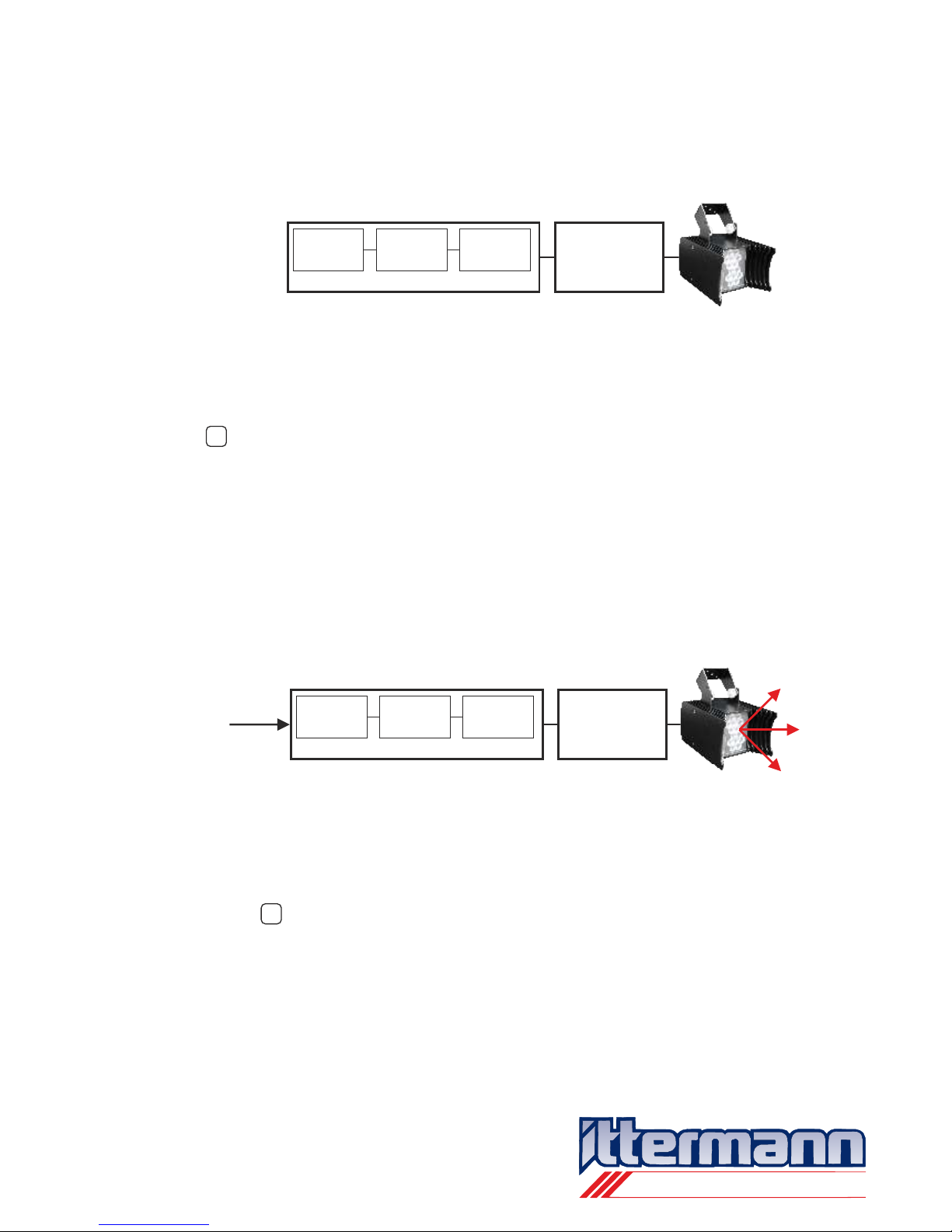
5.2 Installation and electrical connection
- Choose the place of installation of the LED flood light where
adequate air exchange is assured in the neighborhood.
If that is not always possible the active thermic management of
the Ittermann SpotLight LED-flood light prevents a strong
temperature rise of the luminous element and therefore a
reduction of the duration of life.
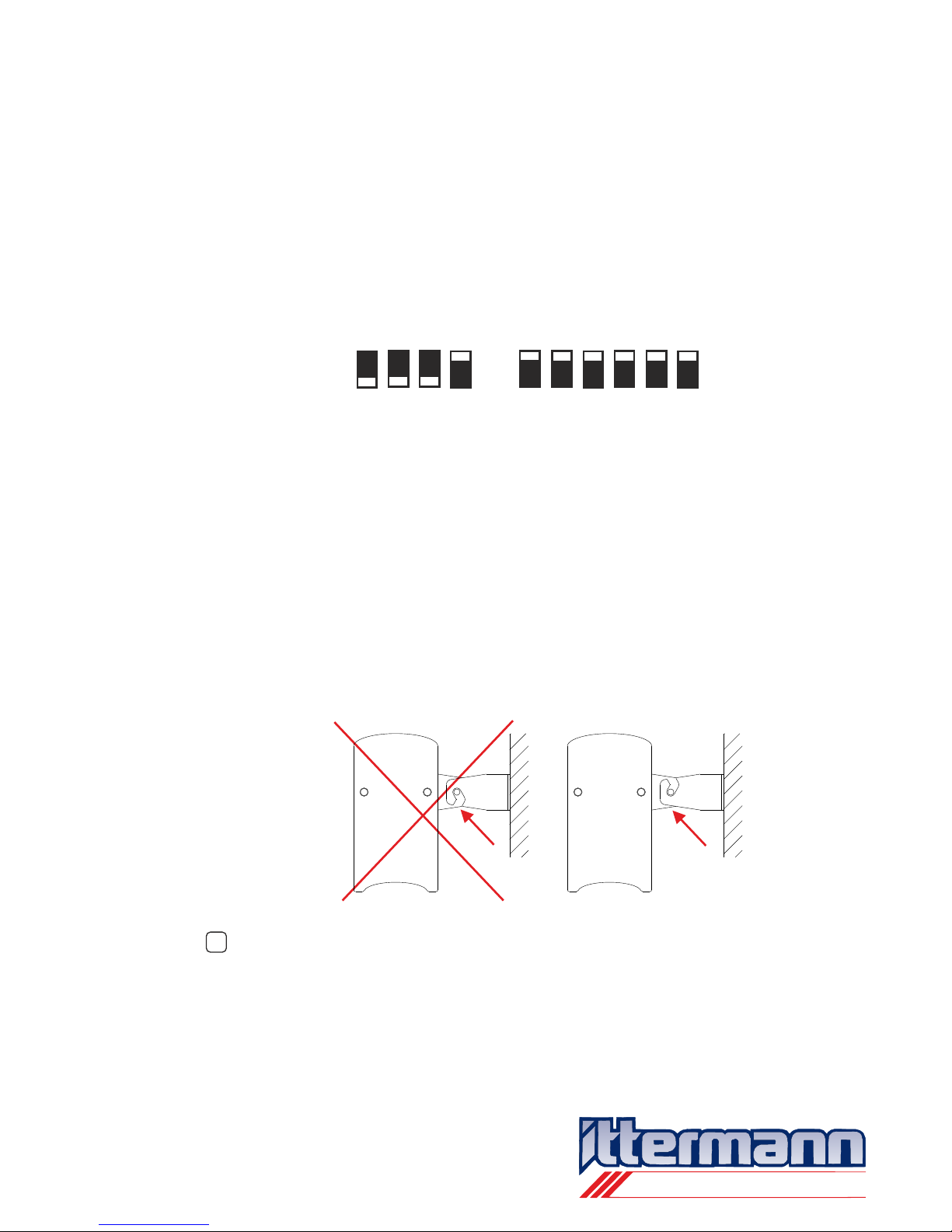
- Please bring the DIP-switches into the following positions:
This switch setting starts the special program No. 17 in StandAlone mode. All LED-groups will be activated one after
another.
- Mount the ceiling- or wall fixing brackets at an applicable place
and tighten the screws strong. The ceiling- or wall fixing bracket
shall only be assembled at a horizontal or vertical seat with
adequate consistency and tensile-loaded capacity.
The montage of the ceiling- or wall fixing bracket should be the
way that it is impossible for the LED flood light, to fall down
Please take care that the knurled nuts a tightened very strong
after hang on and adjust the LED flood light!
Instruction Manual iSL 3014
Dated 09th of June 2011
Page 13/31
i
electronic GmbH
Ittermann electronic GmbH
Köhlergasse 16-18
D - 99842 Ruhla
Phone:
+49 (0)36929
-
75-0
Fax:
+49 (0)36929 - 75-35
Internet:
www.ittermann.de
E-mail:
info@ittermann.de
- Attach the RJ-45 connecting cable (supply) to the LED-flood light
(please use jack “IN”)
- Put the other side of the RJ-45 connecting cable (supply) in the
RJ-45 jack of the connection adapter of the mains adapter 60 W
or 120 W (supply).
Please check before supply voltage if the network power cable is
in order. In case of a damaged network power cable the light
must not get in use.
- Establish the network connection.
Therefore put one side of the network power cable in the mains
adapter 60 W or 120 W (supply) and the other side in a power
jack (230 V).
Please don´t look into the lights directly. Put a sheet of
paper - or something like that - before the light exit.
- For switching off the flood light, pull the power cable.
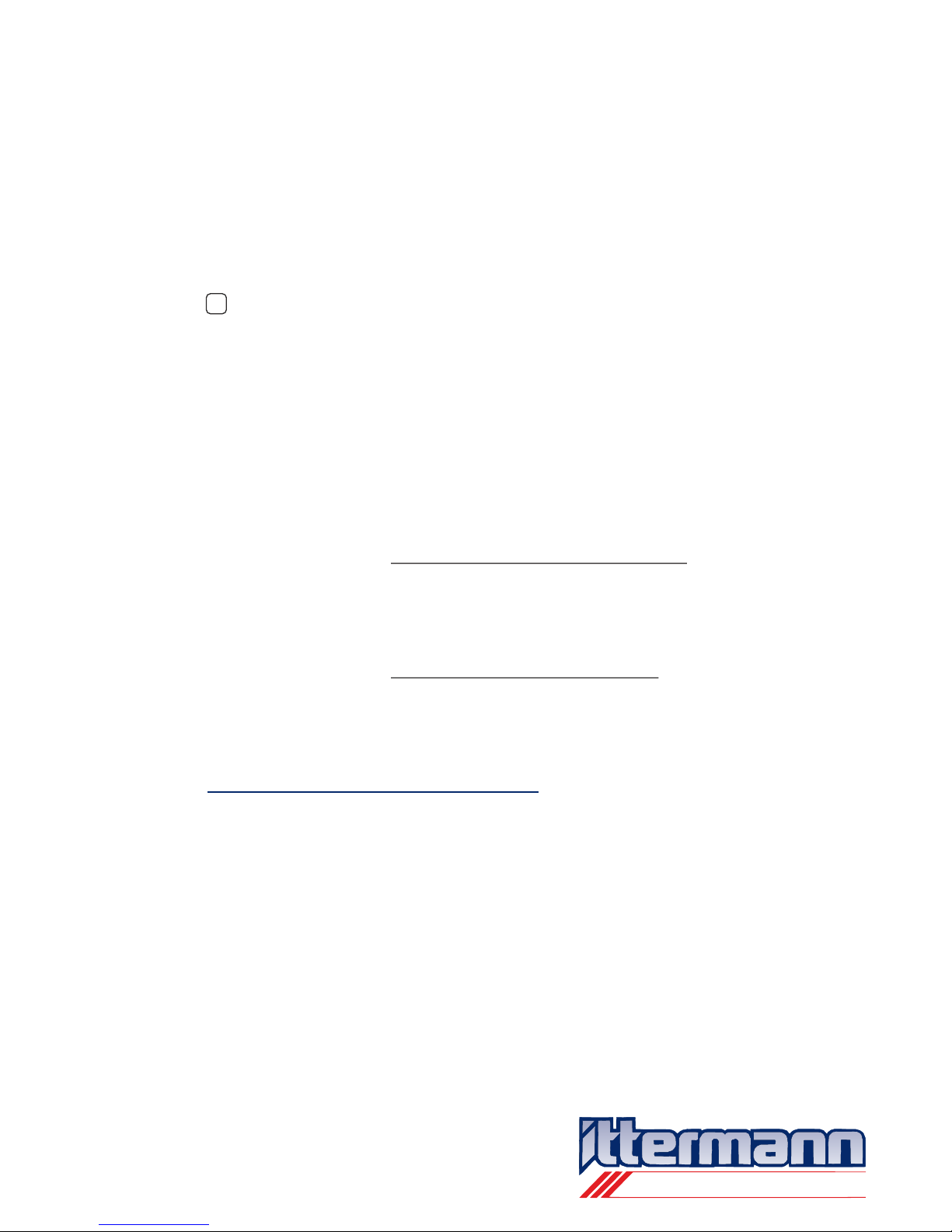
5.3 Transition
- The chosen special program will start.
In this process each LED group will dim up and down.
Instruction Manual iSL 3014
Dated 09th of June 2011
Page 14/31
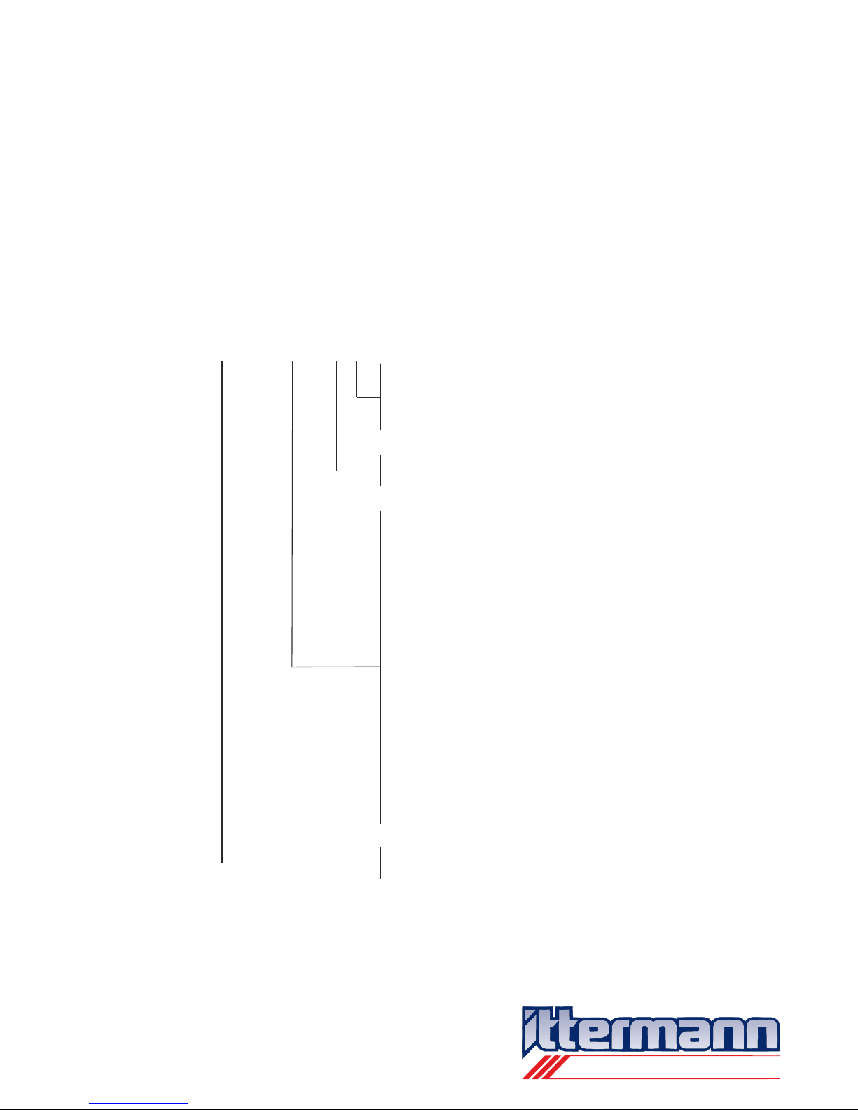
power
supply
60W or 120 W
power
supply
60W or 120 W
connection
adapter
connection
adapter
power
cable
power
cable
supply
supply
supply
supply
RJ-45
connecting cable
RJ-45
connecting cable
system design (schematic picture)
AC 230 V
Light
transition (schematic picture)
i
i

electronic GmbH
Ittermann electronic GmbH
Köhlergasse 16-18
D - 99842 Ruhla
Phone:
+49 (0)36929
-
75-0
Fax:
+49 (0)36929 - 75-35
Internet:
www.ittermann.de
E-mail:
info@ittermann.de
6 Operation
6.1 Preface
6.2 Mode without external control (Stand-Alone mode)
The Itterman SpotLight LED flood light requires – depending on the
type of use – no special knowledge or expert knowledge.
To prevent chilling you with overloaded briefing instructions, we
structured this chapter according to the type of control mode you will
use.
- Chapter 6.2 Mode without external control (Stand-Alone mode):
The usage does not require any special knowledge
- Chapter 6.3 Mode with external control (DMX- and RDM-DMX
mode): Special knowledge necessary
Systemaufbau
As you can see on the demonstrations, you can use only one iSL3014
when using a 60 W . When using a 120 W
you can install a maximum of two iSL3014 in a row. For
connecting the second iSL3014 in the row please use the RJ-45 jack
“OUT”.
The maximum length of the cable in one row: 20 m
power supply power supply
Instruction Manual iSL 3014
Dated 09th of June 2011
Page 15/31
system design with 60 W mains adapter (schematic picture)
system design with 120 W mains adapter (schematic picture)
i
power
supply
60W
connection
adapter
power
cable
supply supply
RJ-45
connecting cable
supply
RJ-45
connecting cable
power
supply
120 W
connection
adapter
power
cable
supply supply
RJ-45
connecting cable

electronic GmbH
Ittermann electronic GmbH
Köhlergasse 16-18
D - 99842 Ruhla
Phone:
+49 (0)36929
-
75-0
Fax:
+49 (0)36929 - 75-35
Internet:
www.ittermann.de
E-mail:
info@ittermann.de
Special programs in Stand-Alone mode
(Description on the example of the iSL3014-RGBW)
Five special programs are available.
Type A Each colour can be switched separately and for each
colour there are four levels of lightness
(0 % = off, 25 %, 75 % and 100 %).
Type B All colours are active, the lightnes is defined by the DIP-
switch SW2; 64 levels of lightness are available.
With RGBW this setting will cause white light with 64
possible lightness levels.
Type C 8 special programs with white and
8 speed levels can be justified.
Type D 8 special programs with stroboscopic effects and
8 speed levels can be justified.
Type E 8 special programs without white and
8 speed levels can be justified.
DIP-switch-adjustments
See appendix A Graphic chart of special programs and DIP-switch
adjustments in Stand-Alone mode (Description on the example of the
iSL3014-RGBW)
6.3 Mode with external control
6.3.1 DMX-Mode
6.3.1.1 Technical information and specific terms
Technical information
Is a standardized digital controlling protocol used in stage- and event
technology.
Instruction Manual iSL 3014
Dated 09th of June 2011
Page 16/31

electronic GmbH
Ittermann electronic GmbH
Köhlergasse 16-18
D - 99842 Ruhla
Phone:
+49 (0)36929
-
75-0
Fax:
+49 (0)36929 - 75-35
Internet:
www.ittermann.de
E-mail:
info@ittermann.de
The DMX controlling protocol is based on a RS-485-interface. The
data transfer occurs symmetric and serial. Because of the symmetric
data transfer DMX has a high interference resistance, because
external errors affect both data links constantly. The receiver analyzes
not
For the construction of connections 5-pole XLR-jacks are specified.
Because it is cheaper 3-pole jacks are used often, too. But that
doesn´t fit the norm.
For the connection lines please use high quality cables, which are able
to transfer the data with high speed (no microphone cables). Capable
are Twisted-Pair-cables with an impedance level of app. 120 ohm.
For connecting the Itermann SpotLight LED-flood lights Cat5-Patch
cable are provided.
see Chapter 4 Supplies
To connect supply voltage and busses of the Ittermann SpotLight
LED-flood light, RJ-45 plug connectors are used. These plug
connectors are usual for ISDN (IAE), structured wiring and computer
networks.
The decision to use for the iSL-LED flood lights RJ-45 plug connectors
has been taken for design reasons. The small and handy design of the
flood light would have not been possible when using XLR-plugs and
moreover an additional plug connector has to be placed for the supply
voltage in that case.
The special RJ-45 configuration of the plug connector on the
Ittermann SpotLight LED-flood light with it´s supplies allows sharing a
maximum of 216 watt in one row (with a supply voltage of 48 V),
without to excess the capacity of the loading system.
For the RJ-45 plug configuration see Chapter 3.4 Technical
Data
the index level but the index difference.
At the transmitter is a socket connector and at
the receiver is a plug connector provided.
Instruction Manual iSL 3014
Dated 09th of June 2011
Page 17/31
i
i

electronic GmbH
Ittermann electronic GmbH
Köhlergasse 16-18
D - 99842 Ruhla
Phone:
+49 (0)36929
-
75-0
Fax:
+49 (0)36929 - 75-35
Internet:
www.ittermann.de
E-mail:
info@ittermann.de
DMX-Networks
DMX-Networks are systems with one transmitter and several receivers
which are connected by bus lines. Transmitter can be e.g. PCs or light
mixing boards and receivers can be e.g. Dimmer, intelligent flood lights
and effect equipment.
The bus stations (transmitter and receiver) are switched back to back
(bus-topology).
One transmitter can be connected to a maximum of 32 receivers. For
more than 32 receivers you have to install a repeater. In case of
branching you should apply splitter (Repeater and splitter amplify and
regenerate the bus signal).
Most bus-technologies start with a transmitter at the beginning of a
chain. To prevent signal-reflections within this constellation – even in
very long chains – it is necessary to install a 120 Ohm-terminator at
the bus-end, after the last receiver. If the transmitter is not located at
the end of a chain, both ends have to be terminated.
The control system roots control information to the receiver by
DMX-protocol. This information is completed by the receivers. You can
power 512 channels with information by using the DMX-protocol.
Channel means, within this context, the controllable function of a
receiver.
The transmitter gets to know how to complete a function by 8 data bits,
which built a DMX-slot together with one start bit and two stop bits.
With 8 data bits a space of 256 DMX-accounts (0 to 255) are possible.
Which function is saved on which channel and is controlled with which
DMX-account is defined by the producer in a DMX-channelconfiguration-chart.
The data transmission works as follows:
One after another a maximum of 512 slots are send by bus lines from
the transmitter to the receivers. Which channel shall use the data of
one slot is regulated by addresses. Each channel gets an address
continuously from 1 to 512. After a start mark each receiver has to
count the transferred slots and filter the special slot which he is able to
react on because of it´s address.
As most receivers in a bus are multifunctional devices, which means
more than one channel has to be controlled, such a device gets a
Instruction Manual iSL 3014
Dated 09th of June 2011
Page 18/31
electronic GmbH
Ittermann electronic GmbH
Köhlergasse 16-18
D - 99842 Ruhla
Phone:
+49 (0)36929
-
75-0
Fax:
+49 (0)36929 - 75-35
Internet:
www.ittermann.de
E-mail:
info@ittermann.de
DMX-start address. This receiver evaluates from the start address the
used number of consecutive slots. The start address of the next
receiver is forwarded of this number of addresses, which the receiver
before has evaluated.
For example: Does the first receiver evaluate in the bus the
addresses 1 – 8, the start address of the next
receiver is 9.
In Chapter 6.3.1.3 “Adjustment of addresses at the DIPSwitches” of the iSL3014, you find the description for the
addressing of the Ittermann SpotLight LED-flood light.
A DMX-Slot consists of:
- one start bit
- one start byte (at the beginning of the DMX package)
respectively 8 data bits (control-information for the single
channels)
- two stop bits.
A DMX-package consists of:
- one “break” (or “reset”) with the logical index 0:
the minimum length has to be 88 µs
- one “mark after break” with the logical index 1:
the minimum length has to be 8 µs
- a first slot, consisting of:
one start bit, one start byte and 2 stop bits
- a “mark” between the slots with the logical index 1
- a second slot, consisting of:
one start bit, 8 data bits (controlling information for the first
channel) and 2 stop bits
- one “mark” between the slots, logical index 1
- The 512nd slot, consisting of one start bit, 8 data bits (controlling
information for the 512nd channel) and 2 stop bit
- one “mark” between the packages, logical index 1.
Configuration and timing of the DMX-protocol
Instruction Manual iSL 3014
Dated 09th of June 2011
Page 19/31
i

electronic GmbH
Ittermann electronic GmbH
Köhlergasse 16-18
D - 99842 Ruhla
Phone:
+49 (0)36929
-
75-0
Fax:
+49 (0)36929 - 75-35
Internet:
www.ittermann.de
E-mail:
info@ittermann.de
All 512 control-information might be, but need not to be transferred. If
the transfer is interrupted any time it can be activated again by
sending a new DMX package. The “break”-sequency is always the
start of a new package.
The start byte has account 0 at DMX. All receivers, which only
understand DMX and no other protocol language (e.g. RDM), must
ignore packages which have a start byte unlike 0.
The speed of data transfer is 250 kbits/s. Therefore the speed of data
transfer for one bit is about 4 µs, for a slot 44 µs (11 x 4 µs) and for a
data package (512 slots) about 22.528 µs (512 x 44 µs).
The length of a DMX package results from the sum of parameter:
+ 88 µs (break)
+ 8 µs (mark after break)
+ 44 µs (first slot with start byte)
+ 22.528 µs (512 slots; data for channels 1 – 512)
= 22.668 µs.
This corresponds to a frequency of 44,11 Hz. The maximum break
between two DMX packages is fixed with 1s.
Instruction Manual iSL 3014
Dated 09th of June 2011
Page 20/31

electronic GmbH
Ittermann electronic GmbH
Köhlergasse 16-18
D - 99842 Ruhla
Phone:
+49 (0)36929
-
75-0
Fax:
+49 (0)36929 - 75-35
Internet:
www.ittermann.de
E-mail:
info@ittermann.de
6.3.1.2 DMX-Networks with iSL3014
The following picture shows the easiest possibility to build a
DMX-Network with the Ittermann SpotLight LED-flood light.
maximum cable length of a chain from iDMX_OUT to
iDMX-LOOP_IN: 20 meters
The maximum cable length depends on the ohmic resistance of the
cable. If a longer chain is necessary special cables need to be used.
Instruction Manual iSL 3014
Dated 09th of June 2011
Page 21/31
DMX OUT
DMX IN
DMX-junction box
supplies
POWER_IN
iDMX_OUT
DMX_IN
DMX_LOOP_OUT
iDMX_LOOP_IN
System design
DMX-junction box and 120 W power supply (schematic picture)
i
power
supply
120 W
connection
adapter
power
cable
supply
supply
RJ-45
connecting cable
supply
RJ-45
connecting cable
supply
RJ-45
connecting cable
supply
RJ-45
connecting cable

electronic GmbH
Ittermann electronic GmbH
Köhlergasse 16-18
D - 99842 Ruhla
Phone:
+49 (0)36929
-
75-0
Fax:
+49 (0)36929 - 75-35
Internet:
www.ittermann.de
E-mail:
info@ittermann.de
6.3.1.3 Adjustment of addresses at the DIP-Switches
Each Ittermann SpotLight LED-flood light is able to evaluate control
information for 8 channels. Therefore 8 back-to-back addresses have
to be created.
At the example of the iSL3014 RGBW these 8 addresses contain
control information for:
- Red LEDs
- Green LEDs
- Blue LEDs
- White LEDs
- Master Dimmer
- special programs 1 to 31
- special parameter 1 (for special programs)
- special parameter 2 (for special programs).
That means every iSL3014 needs a space of 8 byte for addresses.
Red gets the DMX start-address.
On a DMX-512-Bus 64 LED-flood lights can be connected (512/8=64).
Please keep in mind that starting at 32 devices you should install a
repeater.
Instruction Manual iSL 3014
Dated 09th of June 2011
Page 22/31
RED
WHITE
Sprog
SPara 1
SPara 2
MDim
BLUE
GREEN
DMX-address DMX-address +1 DMX-address +2
DMX-address +3
DMX-address +5
DMX-address +6
DMX-address +7
DMX-address +4
Mdim = Master Dimmer (operates on all four colours and channels)
Sprog = Special programs
Spara 1-2 = special parameter 1 to 2
01
1
2
3
5
4
6
SW2
ON
OFF
DMX-address of the iSL3014
1 2
3
4
SW1
ON
OFF
Meaning of the DIP-switch adjustments SW2
Meaning of the DIP-switch adjustments SW1
DMX-mode, address of SW2
(position of SW1-3 and SW1-4 unimportant)
electronic GmbH
Ittermann electronic GmbH
Köhlergasse 16-18
D - 99842 Ruhla
Phone:
+49 (0)36929
-
75-0
Fax:
+49 (0)36929 - 75-35
Internet:
www.ittermann.de
E-mail:
info@ittermann.de
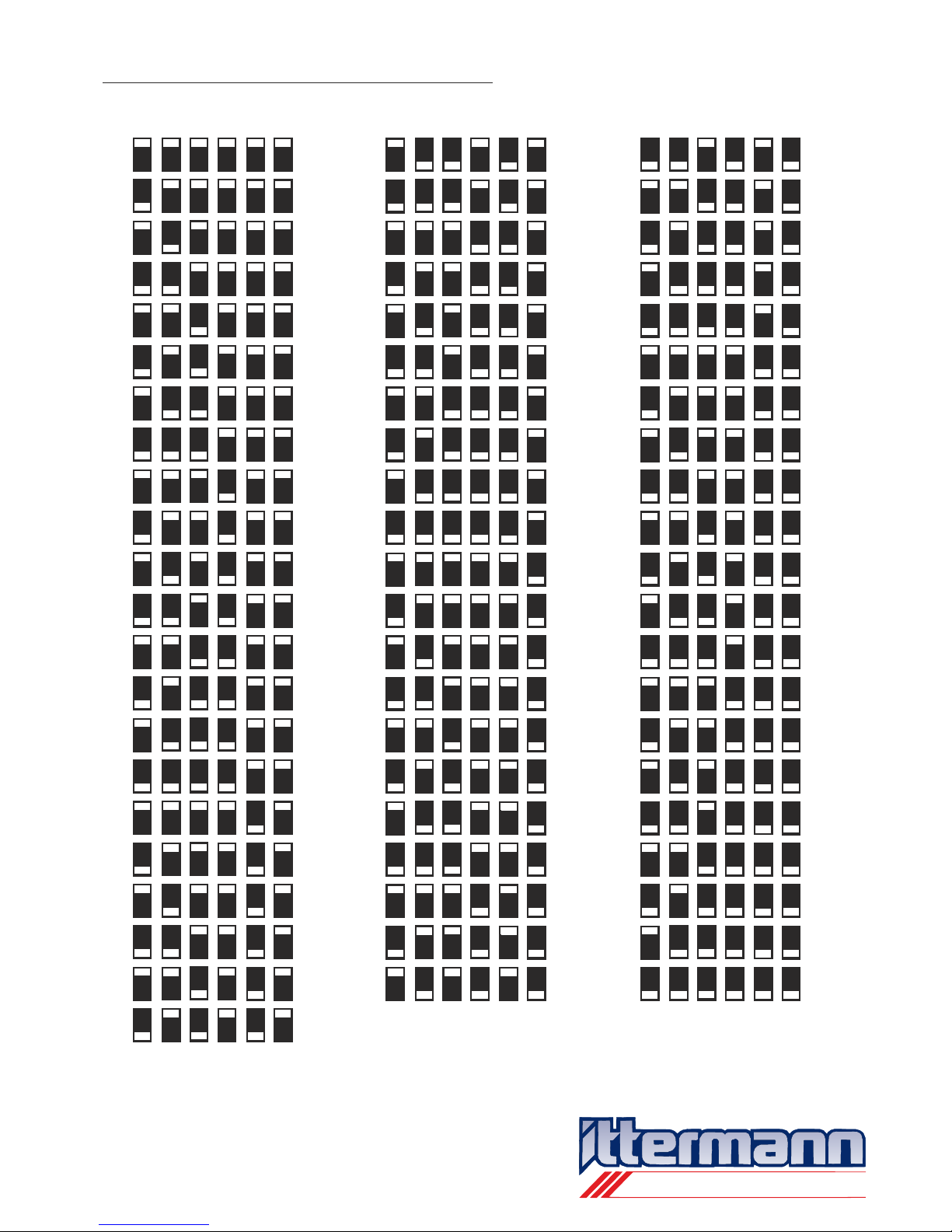
Addressing list by DIP-switch position SW2
001
009
017
025
033
041
049
057
065
073
081
089
097
105
113
121
129
137
145
153
161
169
345
353
361
369
377
385
393
401
409
417
425
433
441
449
457
465
473
481
489
497
505
177
185
193
201
209
217
225
233
241
249
257
265
273
281
289
297
305
313
321
329
337
1
11
2
22
3
33
5
55
4
44
6
66
address
addressaddress
ON
ON
ON
ON
ON
ON
ON
ON
ON
ON
ON
ON
ON
ON
ON
ON
ON
ON
ON
ON
ON
ON
ON
ON
ON
ON
ON
ON
ON
ON
ON
ON
ON
ON
ON
ON
ON
ON
ON
ON
ON
ON
ON
ON
ON
ON
ON
ON
ON
ON
ON
ON
ON
ON
ON
ON
ON
ON
ON
ON
ON
ON
ON
ON
OFF
OFF
OFF
OFF
OFF
OFF
OFF
OFF
OFF
OFF
OFF
OFF
OFF
OFF
OFF
OFF
OFF
OFF
OFF
OFF
OFF
OFF
OFF
OFF
OFF
OFF
OFF
OFF
OFF
OFF
OFF
OFF
OFF
OFF
OFF
OFF
OFF
OFF
OFF
OFF
OFF
OFF
OFF
OFF
OFF
OFF
OFF
OFF
OFF
OFF
OFF
OFF
OFF
OFF
OFF
OFF
OFF
OFF
OFF
OFF
OFF
OFF
OFF
OFF
Instruction Manual iSL 3014
Dated 09th of June 2011
Page 23/31

electronic GmbH
Ittermann electronic GmbH
Köhlergasse 16-18
D - 99842 Ruhla
Phone:
+49 (0)36929
-
75-0
Fax:
+49 (0)36929 - 75-35
Internet:
www.ittermann.de
E-mail:
info@ittermann.de
In difference to the Stand-Alone mode, where only a part of special
programs can be activated by the DIP-switches, within the DMX-mode
it is possible to reach all 31 internal special programs. For that function
channel “Sprog” is designated. The channels “SPara1” and “SPara2”
deliver parameters for special programs, e.g. the time index for the
speed.
A list of all internal special programs is available in Appendix B
Graphic chart of special programs with DMX- and RDM-DMX mode
(Description example iSL3014-RGBW).
This function is only useable if the external control system is
RDM-able. In this case, the DMX-address does not be adjusted at the
DIP-switch SW2 at the Ittermann SpotLight LED-flood light, but can be
written into the internal storage (EEPROM) of the flood light by an
RDM-command. The advantage is that the configuration of a network
in use can be done from a control desk.
The delivery state of all Ittermann SpotLight LED-flood light is
that all have the same address in the internal storage and the
mode level = 0. Therefore they can be used without an
RDM-able external control (see Chapter 6.3.1.3 “Adjustment of
addresses at the DIP-Switches”).
6.3.1.4 DMX-address from the internal storage
Instruction Manual iSL 3014
Dated 09th of June 2011
Page 24/31
01
1
2
3
5
4
6
SW2
ON
OFF
The adjustment of SW2 is not requested
(SW2 unimportant)
1 2
3
4
SW1
ON
OFF
Meaning of the DIP-switch adjustments SW2
Meaning of the DIP-switch adjustments SW1
DMX-mode, address from the internal
storage (adjustment from SW1-3 and
SW 1-4 unimportant)
i

electronic GmbH
Ittermann electronic GmbH
Köhlergasse 16-18
D - 99842 Ruhla
Phone:
+49 (0)36929
-
75-0
Fax:
+49 (0)36929 - 75-35
Internet:
www.ittermann.de
E-mail:
info@ittermann.de
6.3.2 RDM-DMX-Mode
6.3.2.1 Technical information and specific terms
Function notes
RDM is the extension for the DMX-protocol. The valid norm is called
ANSI E1.20-2006.
The permanent send DMX data flow breaks for a short moment (just a
few milliseconds), if after a “Break” the RDM-specific start byte is send
from the transmitter. This sequence signalizes to the receivers, that a
RDM-package is send. A RDM-package is always sent directly to the
receiver. This is possible because the allocation of a unique
identification number (UID = Unique Identify). This number is made up
of the manufacture-ID, which has to be applied for at the ESTA
(Entertainment Services and Technology Association), and the serial
number of the producer.
The receiver evaluates the information of the RDM-package and
sends an answer on the same wire (half duplex). The answering of
more than one participant is avoided by the specific request (Pollen) to
the unique identification number (UID).
Receivers which are not RDM compliant, does not evaluate RDMinformation. They can be contacted by DMX. For that reason you can
mix both types of receiver in one network.
Technical information
To use RDM transmitter, receiver, splitter and repeater have to be
RDM-able.
With RDM the connecting cables of one row have to be terminated at
both ends. The terminator of the transmitter is mostly already installed
in it.
Instruction Manual iSL 3014
Dated 09th of June 2011
Page 25/31

electronic GmbH
Ittermann electronic GmbH
Köhlergasse 16-18
D - 99842 Ruhla
Phone:
+49 (0)36929
-
75-0
Fax:
+49 (0)36929 - 75-35
Internet:
www.ittermann.de
E-mail:
info@ittermann.de
RDM-protocol composition
- RDM-specific start code
- Length of the message
- End address (UID of receiver)
- Source address (ID of transmitter)
- Transaction number
- Port ID / Response Type
- Message count
- Sub-Device
- User data
- Check sum
RDM-commands
The Norm ANSI E1.20-2006 defines, that RDM-able devices have
implemented a minimum-instruction set. These commands are marked
as “Required” in the specification (see ANSI E1.20-2006, chart A-3).
Beside the “Required” commands the Ittermann SpotLight LED-spot
light iSL3014 has implemented specific RDM-commands.
Mode levels of the iSL3014
Mode levels are operating figures, which are used to process the
control information of the 8 channels of the Ittermann SpotLight
LED-flood light.
The ground state of mode level at delivery of the LED-flood light is “0”.
The change of the mode level is only possible by RDM-command.
Mode level 0
Precondition for a control system by DMX
Mode level 1, 2 and 3
Not in use at iSL3014
Instruction Manual iSL 3014
Dated 09th of June 2011
Page 26/31

electronic GmbH
Ittermann electronic GmbH
Köhlergasse 16-18
D - 99842 Ruhla
Phone:
+49 (0)36929
-
75-0
Fax:
+49 (0)36929 - 75-35
Internet:
www.ittermann.de
E-mail:
info@ittermann.de
Mode level 4
RDM-command “Identify Device” applies
Mode level 5
This mode level processes the control information for the
channels 1 – 8, which are saved in the internal storage, which
contains the figures for this mode level. The content of the
storage can only be changed by RDM-command.
Also the figures can be defined as elusive (available until switchoff the power supply) or permanent (are available again after
switch-on the power supply). Please look at the RDM-command
“SET NV-Operating-Mode” in Appendix D.
Mode level 6
The figures, which are saved in the internal storage of mode
level 6 and 7, processes just once (single-shot). These figures
are the control information for channels 1 – 4 (colour light c
hannels). They can only by changed by an according
RDM-command.
Mode level 7
The figures, which are saved in the internal storage of mode
level 6 and 7, processes in an infinite loop. These figures are the
control information for channels 1 – 4 (colour light channels).
They can only by changed by an according RDM-command.
Mode levels 200, 201, 203, 204 and 205
These mode levels show information about the DIP-switch
configuration of SW1. They can be read by a RDM-command but not
changed. Please look at the RDM-command “GET NV-OperatingMode”.
Instruction Manual iSL 3014
Dated 09th of June 2011
Page 27/31

electronic GmbH
Ittermann electronic GmbH
Köhlergasse 16-18
D - 99842 Ruhla
Phone:
+49 (0)36929
-
75-0
Fax:
+49 (0)36929 - 75-35
Internet:
www.ittermann.de
E-mail:
info@ittermann.de
RDM can operate in a processing DMX-network. It is a precondition,
that all members of the network are RDM-able. Also both ends of the
chain have to be terminated.
6.3.2.2 RDM-DMX-networks with iSL3014
Instruction Manual iSL 3014
Dated 09th of June 2011
Page 28/31
1 2
3
4
1
1
1
1
2
2
2
2
3
3
3
3
4
4
4
4
SW1
SW1
SW1
SW1
SW1
ON
ON
ON
ON
ON
OFF
OFF
OFF
OFF
OFF
Mode level 200
(special program / Type A, adjustment
from SW1-3 and SW 1-4 unimportant)
Mode level 201
(special program / Type B)
Mode level 202
(special program / Type C)
Mode level 203
(special program / Type D)
Mode level 204
(special program / Type E)

electronic GmbH
Ittermann electronic GmbH
Köhlergasse 16-18
D - 99842 Ruhla
Phone:
+49 (0)36929
-
75-0
Fax:
+49 (0)36929 - 75-35
Internet:
www.ittermann.de
E-mail:
info@ittermann.de
7 Cleaning, warranty and troubleshooting by user
7.1 Cleaning and warranty
7.2 Troubleshooting
Before cleaning and maintenance please cut the flood-light from
the power supply (pull the power cable). Cool down the LED
flood light!
The Ittermann SpotLight LED-flood light should be cleaned constantly
from dust. Please use a fluff free cloth which is lightly wet. Take care
that no humidity gets into the flood-light (particularly at the back).
Don´t use alcohol or solvent cleanser for the cleaning.
Please check the fixing of the flood light from time to time to preclude
a fall down of it.
Within the Ittermann SpotLight LED-flood light are no parts to be
maintained.
Not each disturbance is caused by a real error. The following to do´s
can be done by your own:
- cut the flood-light from the power supply (pull the power cable)
- check the cable
- check the DIP-switch configuration
- establish the network connection again
In use of an external control system:
Check if the problem is caused by the control or by the flood-light. E.g.
test the iSL3014 in stand-alone mode separately.
If you cannot solve the problems on these ways, send back the floodlight to the producer. The packaging should be chosen carefully to
preclude damages by transportation. We recommend using the
original package.
In case of needing spare parts, please only use original spare parts.
For questions and requirements please contact the producer.
Instruction Manual iSL 3014
Dated 09th of June 2011
Page 29/31
i

electronic GmbH
Ittermann electronic GmbH
Köhlergasse 16-18
D - 99842 Ruhla
Phone:
+49 (0)36929
-
75-0
Fax:
+49 (0)36929 - 75-35
Internet:
www.ittermann.de
E-mail:
info@ittermann.de
8 Guarantee
9 List of spare parts
The charge-free recreation of the operational reliability of the Ittermann
SpotLight LED-flood light within the warranty period of the producer
has the following prerequisites:
- the sales receipt and the notification of warranty claim within the
guarantee period
- the flood-light has to be send to the producer postage free
together with a description of the problem; after the acceptance
of the warranty claim, the producer will refund the cheapest
postage
The packaging should be chosen carefully to preclude damages
by transportation. We recommend using the original package.
The guarantee expires, if:
- the flood-light is damaged
- the flood-light was used or warranted incorrect
- changes have been made without authority
Address of producer and contact details:
Ittermann electronic GmbH
Köhlergasse 16-18
99842 Ruhla
Phone +49 (0)36929 75-0
Fax +49 (0)36929 75-35
E-mail info@ittermann.de
Hompage www.ittermann.de
- Ceiling- or wall fixing brackets
- Knurled nuts
- Foil for the front
- Foil for the back
Instruction Manual iSL 3014
Dated 09th of June 2011
Page 30/31
i

electronic GmbH
Ittermann electronic GmbH
Köhlergasse 16-18
D - 99842 Ruhla
Phone:
+49 (0)36929
-
75-0
Fax:
+49 (0)36929 - 75-35
Internet:
www.ittermann.de
E-mail:
info@ittermann.de
10 Abandonment
11 Subject index
- Cut the flood-light from the power supply (pull the power cable).
- Don´t dispose the flood-light in usual consumer waste.
You have to depollute it at a special disposal for electronic
waste.
Program 6, 10
RDM-command 26f.
RDM-DMX-network 28
RDM-protokol 7, 26
RJ-45 plug configuration 10, 17f.
Special program 6, 16, 22, 24
Stand-Alone-mode 6,9, 12, 15f.
Type of control 6, 15
Thermic management 8, 13
Patges
Mode level 26ff.
DMX-address 18, 22ff.
DMX-network 18f., 21
DMX-package 19f.
DMX-protocol 7, 17, 19ff.
DMX-slot 18f.
DMX- and RDM-DMX mode 6, 16ff.
External control 6,9,12, 16ff.
Channel 18f.
Compliance 4, 5
Luminous element 5
Illuminant 5
RDM-DMX-mode 6, 25ff.
Instruction Manual iSL 3014
Dated 09th of June 2011
Page 31/31

electronic GmbH
Ittermann electronic GmbH
Köhlergasse 16-18
D - 99842 Ruhla
Phone:
+49 (0)36929
-
75-0
Fax:
+49 (0)36929 - 75-35
Internet:
www.ittermann.de
E-mail:
info@ittermann.de
A Appendix
Graphic chart of special programs and DIP-switch adjustments
in Stand-Alone mode
(Description on the example of the iSL3014-RGBW)
A.1 Special programs / Type A (SP / Type A)
Each colour can be switched separately and for each colour there are
four levels of lightness (0 % = off, 25 %, 75 % and 100 %).
Instruction Manual iSL 3014
Dated 09th of June 2011
Appendix A, Page A1/A23
ON
ON
ON
ON
ON
OFF
OFF
OFF
OFF
OFF
Meaning of DIP-switch-adjustments
SW1-3, SW1-4 und SW2-1 bis SW2-6
Meaning of DIP-switch-adjustments
SW1-1, SW1-2
0% = aus
special program / Type A
25%
50%
100% = maximum brightness
112
2
3
3
5
4
4
6
SW1
SW2
ON
ON
OFF
OFF
blue
green
red
white
SP / Type A
= 0% = aus
= 0% = aus
= 0% = aus
= 0% = aus
Examples

electronic GmbH
Ittermann electronic GmbH
Köhlergasse 16-18
D - 99842 Ruhla
Phone:
+49 (0)36929
-
75-0
Fax:
+49 (0)36929 - 75-35
Internet:
www.ittermann.de
E-mail:
info@ittermann.de
Instruction Manual iSL 3014
Dated 09th of June 2011
Appendix A, Page A2/A23
112
2
3
3
5
4
4
6
SW1
SW2
ON
ON
OFF
OFF
blue
green
red
white
SP / Type A
= 100%
= 50%
= 25%
= 0% = aus
112
2
3
3
5
4
4
6
SW1
SW2
ON
ON
OFF
OFF
blue
green
red
white
SP / Type A
= 100%
= 0% = aus
= 0% = aus
= 0% = aus
112
2
3
3
5
4
4
6
SW1
SW2
ON
ON
OFF
OFF
blue
green
red
white
SP / Type A
= 50%
= 0% = aus
= 0% = aus
= 0% = aus
112
2
3
3
5
4
4
6
SW1
SW2
ON
ON
OFF
OFF
blue
green
red
white
SP / Type A
= 25%
= 0% = aus
= 0% = aus
= 0% = aus
Examples

electronic GmbH
Ittermann electronic GmbH
Köhlergasse 16-18
D - 99842 Ruhla
Phone:
+49 (0)36929
-
75-0
Fax:
+49 (0)36929 - 75-35
Internet:
www.ittermann.de
E-mail:
info@ittermann.de
A.2 Special programs / Type C (SP / Type C)
All colours are active, the is defined by the DIP-switch
SW2; 64 levels of are available.
With RGBW this setting will cause white light with 64 possible
levels.
brightness
brightness
brightness
Instruction Manual iSL 3014
Dated 09th of June 2011
Appendix A, Page A3/A23
Examples
1
2
3
5
4
6
SW2
ON
OFF
2% brightness
SP / Type B
1 2
3
4
SW1
ON
OFF
1
2
3
5
4
6
SW2
ON
OFF
50% brightness
25% brightness
12% brightness
7% brightness
4% brightness
2% brightness
1 2
3
4
SW1
ON
OFF
Meaning of DIP-switch-adjustments SW2
Meaning of DIP-switch-adjustments SW1
special program / Typ B

electronic GmbH
Ittermann electronic GmbH
Köhlergasse 16-18
D - 99842 Ruhla
Phone:
+49 (0)36929
-
75-0
Fax:
+49 (0)36929 - 75-35
Internet:
www.ittermann.de
E-mail:
info@ittermann.de
Instruction Manual iSL 3014
Dated 09th of June 2011
Appendix A, Page A4/A23
1
2
3
5
4
6
SW2
ON
OFF
2%+12%+50%= 64%
brightness
SP / Type B
1 2
3
4
SW1
ON
OFF
1
2
3
5
4
6
SW2
ON
OFF
2%+4%+7%=13%
brightness
SP / Type B
1 2
3
4
SW1
ON
OFF
Examples
1
2
3
5
4
6
SW2
ON
OFF
2%+4%=6% brightness
SP / Type B
1 2
3
4
SW1
ON
OFF

electronic GmbH
Ittermann electronic GmbH
Köhlergasse 16-18
D - 99842 Ruhla
Phone:
+49 (0)36929
-
75-0
Fax:
+49 (0)36929 - 75-35
Internet:
www.ittermann.de
E-mail:
info@ittermann.de
A.3 Special programs / Type C (SP / Type C)
8 special programs with white and 8 speed levels can be justified.
Instruction Manual iSL 3014
Dated 09th of June 2011
Appendix A, Page A5/A23
1
1
1
1
1
1
1
1
1
1
1
1
1
1
1
1
2
2
2
2
2
2
2
2
2
2
2
2
2
2
2
2
3
3
3
3
3
3
3
3
3
3
3
3
3
3
3
3
5
5
5
5
5
5
5
5
5
5
5
5
5
5
5
5
4
4
4
4
4
4
4
4
4
4
4
4
4
4
4
4
6
6
6
6
6
6
6
6
6
6
6
6
6
6
6
6
SW2
SW2
SW2
SW2
SW2
SW2
SW2
SW2
SW2
SW2
SW2
SW2
SW2
SW2
SW2
SW2
ON
ON
ON
ON
ON
ON
ON
ON
ON
ON
ON
ON
ON
ON
ON
ON
OFF
OFF
OFF
OFF
OFF
OFF
OFF
OFF
OFF
OFF
OFF
OFF
OFF
OFF
OFF
OFF
SP 17
1
SP 18
2
SP 19
5
SP 20
10
SP 21
50
SP 29
200
SP 30
1000
SP 31
5000
Meaning of DIP-switch-adjustments SW2
special program number
speed
1 2
3
4
SW1
ON
OFF
Meaning of DIP-switch-adjustments SW1
special program / Type C

Instruction Manual iSL 3014
Dated 09th of June 2011
Appendix A, Page A6/A23
OFF
OFF
Sp / Type C
Sp / Type C
112
2
3
3
4
4
SW1
SW1
ON
ON
OFF
OFF
1
1
2
2
3
3
5
5
4
4
6
6
SW2
SW2
ON
ON
speed: 1
speed: 2
SP 17
SP 17
Examples

Instruction Manual iSL 3014
Dated 09th of June 2011
Appendix A, Page A7/A23
OFF
OFF
Sp / Type C
Sp / Type C
112
2
3
3
4
4
SW1
SW1
ON
ON
OFF
OFF
1
1
2
2
3
3
5
5
4
4
6
6
SW2
SW2
ON
ON
speed: 200
speed: 5000
SP 17
SP 17
Examples

Instruction Manual iSL 3014
Dated 09th of June 2011
Appendix A, Page A8/A23
OFF
OFF
Sp / Type C
Sp / Type C
112
2
3
3
4
4
SW1
SW1
ON
ON
OFF
OFF
1
1
2
2
3
3
5
5
4
4
6
6
SW2
SW2
ON
ON
speed: 1
speed: 1
SP 18
SP 19
Examples

Instruction Manual iSL 3014
Dated 09th of June 2011
Appendix A, Page A9/A23
OFF
OFF
Sp / Type C
Sp / Type C
112
2
3
3
4
4
SW1
SW1
ON
ON
OFF
OFF
1
1
2
2
3
3
5
5
4
4
6
6
SW2
SW2
ON
ON
speed: 1
speed: 1
SP 20
SP 21
Examples

Instruction Manual iSL 3014
Dated 09th of June 2011
Appendix A, Page A10/A23
OFF
OFF
Sp / Type C
Sp / Type C
112
2
3
3
4
4
SW1
SW1
ON
ON
OFF
OFF
1
1
2
2
3
3
5
5
4
4
6
6
SW2
SW2
ON
ON
speed: 200
speed: 1000
SP 29 ( ) increasingly warm white
SP 30 ( ) change from cold white to warm white
Examples
zoom factor oft the grafic: 2

Instruction Manual iSL 3014
Dated 09th of June 2011
Appendix A, Page A11/A23
OFF
Sp / Type C
1 2
3
4
SW1
ON
OFF
1
2
3
5
4
6
SW2
ON
speed: 200
SP 31 ( ) change from warm white cold white
Examples
The programs 29, 30 and 31 are sample applications to create
deticated colour temperatures of white light.
The production of the sleep hormone Melatonin is among others
controlled by the blue part of light. Therefore in the evening - for
example - by the reduction of blue parts of the light the
Melatoninproduction can be stimulated with the result that humans get
tired. The other way round it is possible by exalting the blue part of the
light, to reduce the Melatoninproduction, which might it make easier to
wake up in the morning.
For that reason it is recommendable to use warm red light in the
evening and cold blue white light in the morning to keep the inside
clock of humans in a balance.

electronic GmbH
Ittermann electronic GmbH
Köhlergasse 16-18
D - 99842 Ruhla
Phone:
+49 (0)36929
-
75-0
Fax:
+49 (0)36929 - 75-35
Internet:
www.ittermann.de
E-mail:
info@ittermann.de
A.4 Special programs / Type D (SP / Type D)
8 special programs with stroboscopic effects and
8 speed levels can be justified.
Instruction Manual iSL 3014
Dated 09th of June 2011
Appendix A, Page A12/A23
1
1
1
1
1
1
1
1
1
1
1
1
1
1
1
1
2
2
2
2
2
2
2
2
2
2
2
2
2
2
2
2
3
3
3
3
3
3
3
3
3
3
3
3
3
3
3
3
5
5
5
5
5
5
5
5
5
5
5
5
5
5
5
5
4
4
4
4
4
4
4
4
4
4
4
4
4
4
4
4
6
6
6
6
6
6
6
6
6
6
6
6
6
6
6
6
SW2
SW2
SW2
SW2
SW2
SW2
SW2
SW2
SW2
SW2
SW2
SW2
SW2
SW2
SW2
SW2
ON
ON
ON
ON
ON
ON
ON
ON
ON
ON
ON
ON
ON
ON
ON
ON
OFF
OFF
OFF
OFF
OFF
OFF
OFF
OFF
OFF
OFF
OFF
OFF
OFF
OFF
OFF
OFF
SP 16.1
1
SP 16.2
3
SP 16.3
5
SP 16.4
10
SP 16.5
20
SP 16.6
50
SP 16.7
100
SP 16.8
250
Meaning of DIP-switch-adjustments SW2
special program number
speed
1 2
3
4
SW1
ON
OFF
Meaning of DIP-switch-adjustments SW1
special proram / Type D

Instruction Manual iSL 3014
Dated 09th of June 2011
Appendix A, Page A13/A23
OFF
OFF
Sp / Type D
Sp / Type D
112
2
3
3
4
4
4
SW1
SW1
ON
ON
OFF
OFF
1
1
2
2
3
3
5
5
4
4
6
6
6
SW2
SW2
ON
ON
speed: 100
speed: 100
SP 16.1
SP 16.2
Examples

Instruction Manual iSL 3014
Dated 09th of June 2011
Appendix A, Page A14/A23
OFF
OFF
Sp / Type D
Sp / Type D
112
2
3
3
4
4
4
SW1
SW1
ON
ON
OFF
OFF
1
1
2
2
3
3
5
5
4
4
6
6
6
SW2
SW2
ON
ON
speed: 100
speed: 100
SP 16.3
SP 16.4
Examples

Instruction Manual iSL 3014
Dated 09th of June 2011
Appendix A, Page A15/A23
OFF
OFF
Sp / Type D
Sp / Type D
112
2
3
3
4
4
4
SW1
SW1
ON
ON
OFF
OFF
1
1
2
2
3
3
5
5
4
4
6
6
6
SW2
SW2
ON
ON
speed: 100
speed: 100
SP 16.5
SP 16.6
Examples

Instruction Manual iSL 3014
Dated 09th of June 2011
Appendix A, Page A16/A23
OFF
OFF
Sp / Type D
Sp / Type D
112
2
3
3
4
4
4
SW1
SW1
ON
ON
OFF
OFF
1
1
2
2
3
3
5
5
4
4
6
6
6
SW2
SW2
ON
ON
speed: 100
speed: 100
SP 16.7
SP 16.8
Examples

electronic GmbH
Ittermann electronic GmbH
Köhlergasse 16-18
D - 99842 Ruhla
Phone:
+49 (0)36929
-
75-0
Fax:
+49 (0)36929 - 75-35
Internet:
www.ittermann.de
E-mail:
info@ittermann.de
A.5 Special programs / Type E (SP / Type E)
8 special programs without white and 8 speed levels can be
justified.
Instruction Manual iSL 3014
Dated 09th of June 2011
Appendix A, Page A17/A23
1
1
1
1
1
1
1
1
1
1
1
1
1
1
1
1
2
2
2
2
2
2
2
2
2
2
2
2
2
2
2
2
3
3
3
3
3
3
3
3
3
3
3
3
3
3
3
3
5
5
5
5
5
5
5
5
5
5
5
5
5
5
5
5
4
4
4
4
4
4
4
4
4
4
4
4
4
4
4
4
6
6
6
6
6
6
6
6
6
6
6
6
6
6
6
6
SW2
SW2
SW2
SW2
SW2
SW2
SW2
SW2
SW2
SW2
SW2
SW2
SW2
SW2
SW2
SW2
ON
ON
ON
ON
ON
ON
ON
ON
ON
ON
ON
ON
ON
ON
ON
ON
OFF
OFF
OFF
OFF
OFF
OFF
OFF
OFF
OFF
OFF
OFF
OFF
OFF
OFF
OFF
OFF
SP 1
1
SP 2
2
SP 3
5
SP 4
10
SP 5
50
SP 6
200
SP 7
1000
SP 11
5000
Meaning of DIP-switch-adjustments SW2
special program number
speed
1 2
3
4
SW1
ON
OFF
Meaning of DIP-switch-adjustments SW1
special program / Type E

Instruction Manual iSL 3014
Dated 09th of June 2011
Appendix A, Page A18/A23
OFF
OFF
Sp / Type E
Sp / Type E
112
2
3
3
4
4
SW1
SW1
ON
ON
OFF
OFF
1
1
2
2
3
3
5
5
4
4
6
6
SW2
SW2
ON
ON
speed: 1
speed: 2
SP 1
SP 1
Examples

Instruction Manual iSL 3014
Dated 09th of June 2011
Appendix A, Page A19/A23
OFF
OFF
Sp / Type E
Sp / Type E
112
2
3
3
4
4
SW1
SW1
ON
ON
OFF
OFF
1
1
2
2
3
3
5
5
4
4
6
6
SW2
SW2
ON
ON
speed: 200
speed: 5000
SP 1
SP 1
Examples
Instruction Manual iSL 3014
Dated 09th of June 2011
Appendix A, Page A20/A23
OFF
OFF
Sp / Type E
Sp / Type E
112
2
3
3
4
4
SW1
SW1
ON
ON
OFF
OFF
1
1
2
2
3
3
5
5
4
4
6
6
SW2
SW2
ON
ON
speed: 1
speed: 1
SP 2
SP 3
Examples

Instruction Manual iSL 3014
Dated 09th of June 2011
Appendix A, Page A21/A23
OFF
OFF
Sp / Type E
Sp / Type E
112
2
3
3
4
4
SW1
SW1
ON
ON
OFF
OFF
1
1
2
2
3
3
5
5
4
4
6
6
SW2
SW2
ON
ON
speed: 1
speed: 1
SP 4
SP 5
Examples
Instruction Manual iSL 3014
Dated 09th of June 2011
Appendix A, Page A22/A23
OFF
OFF
Sp / Type E
Sp / Type E
112
2
3
3
4
4
SW1
SW1
ON
ON
OFF
OFF
1
1
2
2
3
3
5
5
4
4
6
6
SW2
SW2
ON
ON
speed: 1
speed: 1
SP 6
SP 7
Examples
Instruction Manual iSL 3014
Dated 09th of June 2011
Appendix A, Page A23/A23
OFF
Sp / Type E
1 2
3
4
SW1
ON
OFF
1
2
3
5
4
6
SW2
ON
speed: 1
SP 11
Examples

electronic GmbH
Ittermann electronic GmbH
Köhlergasse 16-18
D - 99842 Ruhla
Phone:
+49 (0)36929
-
75-0
Fax:
+49 (0)36929 - 75-35
Internet:
www.ittermann.de
E-mail:
info@ittermann.de
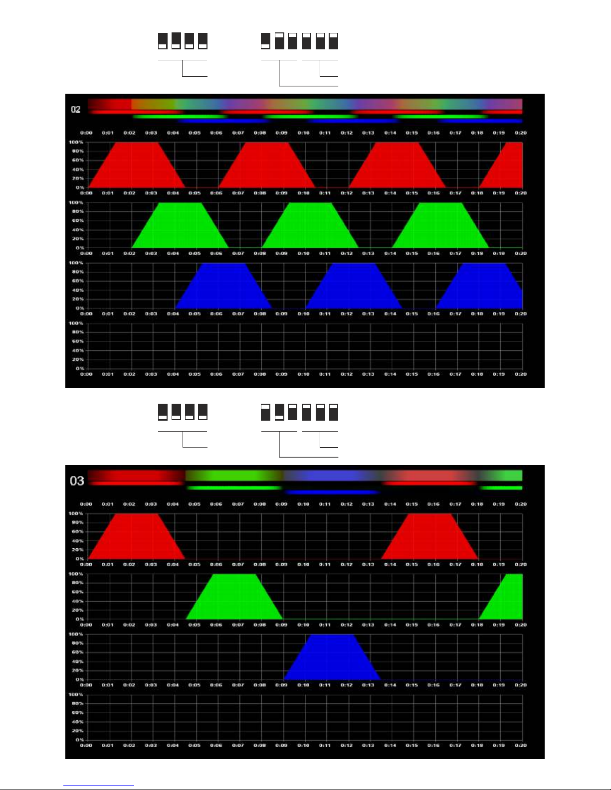
B Appendix
Graphic chart of special programs with DMX- and
RDM-DMX-mode (Description example iSL3014-RGBW)
Instruction Manual iSL 3014
Dated 09th of June 2011
Appendix B, Page B1/B6
special program1 with speed 1
special program 3 with speed 1
special program 5 with speed 1
special program 2 with speed 1
special program 4 with speed 1
special program 6 with speed 1

electronic GmbH
Ittermann electronic GmbH
Köhlergasse 16-18
D - 99842 Ruhla
Phone:
+49 (0)36929
-
75-0
Fax:
+49 (0)36929 - 75-35
Internet:
www.ittermann.de
E-mail:
info@ittermann.de
Instruction Manual iSL 3014
Dated 09th of June 2011
Appendix B, Page B2/B6
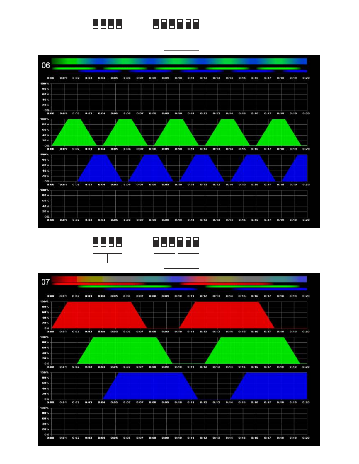
special program 7 with speed 1
special program 9 with speed 1
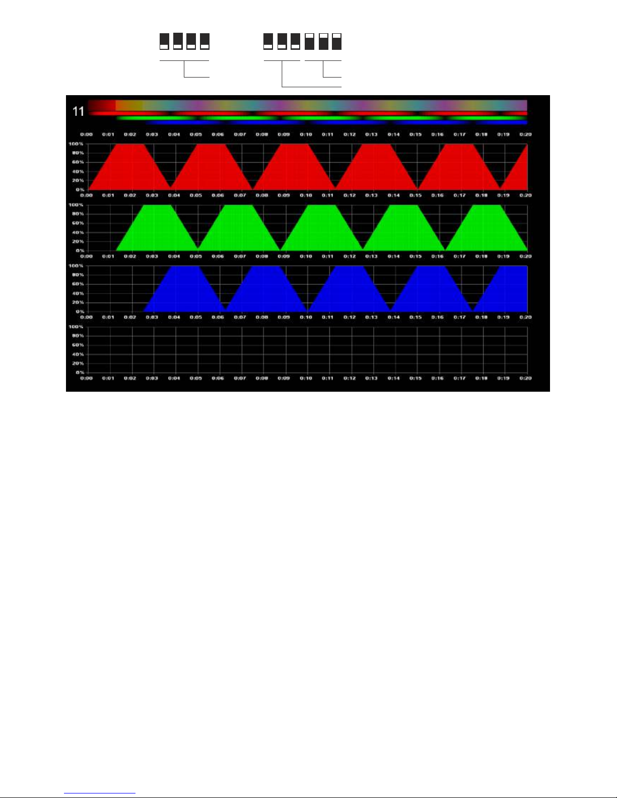
special program 11 with speed 1
special program 13 with speed 1
special program 8 with speed 1
special program 10 with speed 1
special program 12 with speed 1
special program 14 with speed 1
electronic GmbH
Ittermann electronic GmbH
Köhlergasse 16-18
D - 99842 Ruhla
Phone:
+49 (0)36929
-
75-0
Fax:
+49 (0)36929 - 75-35
Internet:
www.ittermann.de
E-mail:
info@ittermann.de
Instruction Manual iSL 3014
Dated 09th of June 2011
Appendix B, Page B3/B6
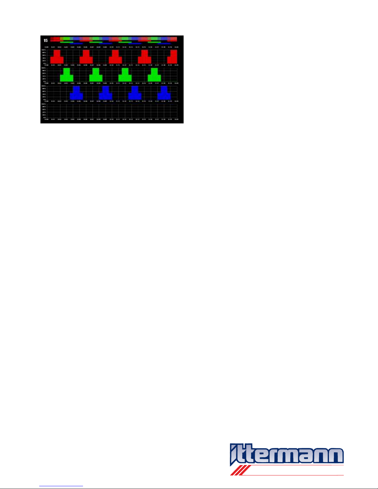
special program 15 with speed 1

electronic GmbH
Ittermann electronic GmbH
Köhlergasse 16-18
D - 99842 Ruhla
Phone:
+49 (0)36929
-
75-0
Fax:
+49 (0)36929 - 75-35
Internet:
www.ittermann.de
E-mail:
info@ittermann.de
Instruction Manual iSL 3014
Dated 09th of June 2011
Appendix B, Page B4/B6
special program 16-1 with speed 100
special program 16-3 with speed 100
special program 16-5 with speed 100
special program 16-7 with speed 100
special program 16-2 with speed 100
special program 16-4 with speed 100
special program 16-6 with speed 100
special program 16-8 with speed 100

electronic GmbH
Ittermann electronic GmbH
Köhlergasse 16-18
D - 99842 Ruhla
Phone:
+49 (0)36929
-
75-0
Fax:
+49 (0)36929 - 75-35
Internet:
www.ittermann.de
E-mail:
info@ittermann.de
Instruction Manual iSL 3014
Dated 09th of June 2011
Appendix B, Page B5/B6
special program 17 with speed 1
special program 19 with speed 1
special program 11 with speed 1
special program 23 with speed 1
special program 18 with speed 1
special program 20 with speed 1
special program 22 with speed 1
special program 24 with speed 1

electronic GmbH
Ittermann electronic GmbH
Köhlergasse 16-18
D - 99842 Ruhla
Phone:
+49 (0)36929
-
75-0
Fax:
+49 (0)36929 - 75-35
Internet:
www.ittermann.de
E-mail:
info@ittermann.de
Instruction Manual iSL 3014
Dated 09th of June 2011
Appendix B, Page B6/B6
special program 25 with speed 1
special program 27 with speed 1
special program 29 with speed 1
special program 31 with speed 1
special program 26 with speed 1
special program 28 with speed 1
special program 30 with speed 1
 Loading...