

Page 1

WEDECO Aquada
GB
DE
F
Installation and Maintenance Instructions
Installations- und Wartungsanleitung
Notice d’installation et de Maintenance
I
Istruzioni di Installazione e Manutenzione
Page 2

Contents
1. General&Applications
2. Assembly&Installation
2.1. Reactor
2.1.1. Assembly of Reactor
2.1.2. Installation of Quartz Sleeve and of UV Lamp
2.1.2.1. Cleaning and Replacement of Quartz Sleeve
2.1.2.2. Fitting of UV Sensor (only for Maxima)
2.1.3. Connection to the Water Line Network
2.2. ControlSystem
2.2.1. Assembly of Control Box
2.2.2. Electrical Connection
2.2.3. Connection of UV Lamp
3. Commissioning
3.1. Units with Solenoid Valve
3.1.1. Units without Solenoid Valve
3.2. Tightness Test
4. Software
4.1. Alarm Messages
4.2. New Start after Replacement of UV Lamp
5. ExplodedDiagram
6. SparePartsList
7. Declarationofconformity(page82)
ATTENTION:
Please read this manual carefully and follow the instructions given in it.
Installation must be carried out only by authorized technicians.
2
Page 3

1. General & Applications
Disinfection by means of ultraviolet light (UV) is an efficient, economic and particularly environmentally friendly process.
UV light kills pathogene microorganisms within a few seconds without leaving any
residues, harmful by-products or affecting the sense of smell or of taste.
Thanks to this the operators‘ exposure to danger by handling harmful chemicals is
excluded.
The effect of the UV light is used by very effective UV-C radiation (254 Nm). Within
a few seconds this brings about a photochemical reaction in DNA (desoxyribonucleic acid) which is vital for all microorganisms. By this microorganisms are either killed
or their ability to increase is destroyed.
The rate of kill depends on minimum UV radiation (UV dose), i.e. the time that a microorganism is exposed to a certain intensity of UV radiation (W/m²). At a UV dose
of 400 J/m² the most important human pathogene bacteria and virus are reduced
by 4 logs (decimal exponents), which corresponds to international requirements
and ensures safe disinfection.
The disinfection performance of a UV system is essentially based on the fact that
each volume element obtains the necessary UV dose when it passes through the UV
reactor. To ensure this the radiation field and hydraulic properties in the UV system
have been optimally adapted to each other.
UV radiation of drinking water does not cause any undesired secondary reactions
based on the UV doses we use for disinfection.
As we do not add efficient disinfective substances to the water by UV radiation,
there are no deposit effects when the volume element has passed through the UV
reactor.
ATTENTION:
Correct function (disinfection performance) can only be guaranteed when original ITT Water & Wastewater spare parts (lamps,
ballasts, etc. ) are used.
Should you have any questions please contact:
www.wedeco.com
Tel.: +49 (0) 5221 930-777
Fax : +49 (0) 5221 930-196
3
GB
Page 4

General Safety Instructions
ELECTRIC SHOCK!
Attention - dangerous electrical voltage. The non-observance of this
instruction can cause serious personal injuries.
ENSURE EYE PROTECTION IS WORN!
IMPORTANT!
Instruction regarding useful tips or other information.
CAUTION!
UV-C radiation is harmful to the eyes and skin! UV lamps should be used
only in the irradiation chamber if suitable protection caps have been fitted.
Persons should never be exposed to UV-C radiation.
• Make sure this disinfection unit is only used for the intended purpose as describ ed in the operating instructions. The use of additional apparatus, which have not
been recommended by and are not sold by ITT Water & Wastewater can cause an
unsafe situation.
• This disinfection unit is to be installed properly before use according to the opera ting instructions
• Do not use a unit with damaged electrical lead or plug, or a unit with faulty func tions, or a unit, which has been dropped or has been damaged in some way
• Make sure the unit is unplugged when it is not being used before fitting, or remo ving any parts, or before cleaning the unit. Do not remove the plug from the
socket by pulling the electrical lead, but take the plug directly out of the socket.
4
Page 5

• Ensure the disinfection unit is electrically isolated before:
A. Carrying out repairs
REMARK:
Werecommendthatanymaintenanceiscarriedoutbyqualifiedpersons.
B. Cleaning
C. Replacement of the UV lamp
• The unit is to be depressurized before maintenance
• Do not use the UV lamp outside of the UV disinfection reactor
UV systems, which have been equipped with a solenoid valve,
should not be used without flowing water for long periods
(max. 48 hours). In cases of longer absence the system is to be
put out of operation.
WEDECO UV lamps have been designed for permanent operation
to reach their best disinfection capacity.
Frequent switching on and off reduces the life of the UV lamp!
Max. 200 switching operations!
5
GB
Page 6

2. Assembly & Installation
The following items must be checked prior to installation:
• A max. operating pressure of 1000 K Pa (10 bar) must not be exceeded
• The max. ambient temperature is 40° C
• The max. water temperature is 25° C
• The max. flow rate must not be exceeded (see section 2.1.)
• The installation site of the reactor must be frost-protected and dry
2.1. Reactor
The following reactor types are available in the Aquada series:
*
Flow rate: 400 J/m2, UV-Transmission: 94 %
Make sure the national standards and prescriptions for assembly and installation are observed. Installation must be carried
out only by qualified technicians.
Type Length Diameter Connections„Min. free space
above reactor
Max. flow rate*
m
3
/h
1 470 mm 70 mm R 1/2 370 mm 0,70
2 670 mm 70 mm R 3/4 570 mm 1,77
4 670 mm 101,6 mm R 3/4 570 mm 3,01
7 1030 mm 101,6 mm R1 920 mm 6,20
10 1030 mm 140 mm R1 1/2 920 mm 9,00
6
Page 7

2.1.1. Assembly of Reactor
• Before installation ensure you know which reactor type you are using.
(Information about the reactor type can be found on the type plate)
• Make sure that there is enough free space above the reactor (for dimensions see
section 2.1.), otherwise it will not be possible to install the UV lamp and to
maintain the system
• The reactor is to be fixed by means of the enclosed assembly clips either on the
wall or on a special holder
• In units with a UV sensor the reactor can only be assembled in a vertical position
• The assembled reactor is to be protected from frost exposure
UV lamp
Outlet
UV sensor (optional)
Control box
Inlet
7
GB
Page 8

2.1.2. Installation of Quartz Sleeve and of UV Lamp
The reactor is supplied together with a built-in quartz sleeve. The black head piece
in which the UV lamp is to be inserted has been screwed to a tightness of 5 Nm
in our factory. Prior to commissioning all screw connections are to be checked for
tightness.
ForinstallationofUVlampseesection2.2.3.
2.1.2.1. Cleaning and Replacement of Quartz Sleeve
The transparent plug of the lamp connection is to be turned slightly to the left or
the right (up to the raised part in the head piece) and then removed.
Remove UV lamp from the reactor by pressing the two transparent catching tabs.
Unscrew head piece from reactor and then carefully remove it together with the
quartz sleeve.
Then remove any coating from the quartz sleeve and reassemble it after cleaning.
The quartz sleeve and the head piece are two single parts.
In case of disassembly, hold both parts in order to avoid the
quartz sleeve slipping out of the head piece!
UV lamp
O-ring
Lamp filament wiring
Quartz sleeve
Head piece Catching tabs
UV lamp
O-ring
8
Page 9

Assembling manual
The transparent lamp connector must properly snap
into the groove on the head
piece.
The UV lamp is also to be
cleaned before assembly.
It is to be inserted into the
head piece from above until
the two transparent catching
tabs of the connecting plug
lock into place in the head
piece.
After the assembly of the UV
lamp the transparent lamp
connecting plug is to be fitted on the head piece. Make
sure that it locks into place.
(Seeguideintheplug)
This figure shows the transparent lamp connector
pushed too far.
Head piece UV lamp
Transparent connecting plug
Put the connection plug onto
the head piece until it clicks
in.
The connection plug is
properly installed. It does not
seperate when pulled away
from the head piece.
UV lamp
Transparent lamp
connection
Head piece
9
GB
Page 10

2.1.2.2. Fitting of UV Sensor
In our factory the UV sensor has been fitted to the control (only for Maxima model).
It is only to be screwed to the reactor. Tightening should be carried out with a light
tool only. A starting torque of 5 Nm is sufficient. Make sure this torque is not exceeded, otherwise the quartz glass in the sensor may be damaged.
To avoid breakage, do not remove the quartz glass plate (located in the sensor)
when cleaning it. The glass plate should only be cleaned with a soft, clean cloth.
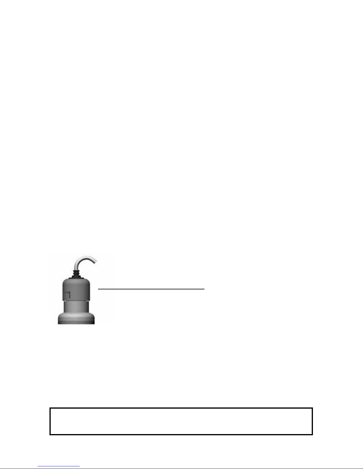
2.1.3. Connection to the Water Line Network
• When carrying out the connection to the water line network make sure to fit stop
valves on the inlet and outlet of the reactor to make maintenance easier
• UV resistant material is to be used for the connections to the water line network.
For the connection sizes please refer to the table in section 2.1.
• The connection to water line network is to be carried out in accordance with the
national regulations
• A solenoid valve is offered as an optional (Proxima, Maxima). This prevents wa ter flowing through in the case of power failure or insufficient UV intensity in the
reactor
UV sensor
NOTE:
The sensor is to be cleaned in regular intervals depending on the water
quality. For this purpose unscrew sensor after it has been depressurized
and is free from water, and then clean the quartz glass with the cleaner.
10
Page 11
2.2. Control System
The following equipment variants can be supplied:
1.Altima
• Visual function control of UV lamp by transparent lamp connection
• Control box which can be fastened easily (assembly on the wall or reactor)
2.Proxima
• As Altima variant
• Possibility of connecting a solenoid valve which allows water flow only in the case
of a shining UV lamp
• Control of the solenoid valve by a micro-controller
• Remaining life of UV lamp shown on the display
• Visual and acoustic alarm in the case of lamp failure
3.Maxima
• As Proxima variant
• A UV sensor which continuously monitors the intensity, switches off the solenoid
valve when the minimum intensity is not reached and emits a visual and acoustic
alarm. The intensity is shown on the display.
11
GB
Page 12

2.2.1. Assembly of the Control Box
The control box can be fitted directly to the reactor by means of the supplied fastening bands.
• Assembly on the wall is also possible. For this method drill two holes
(hole spacing 134 mm) and fit dowels and screws. Then the control
housing can be hung on the screws.
• In the case of wall mounting the lengths of the supplied cables are to be taken
into account
» Connecting line to the mains: 200 cm
» Sensor cable: 150 cm (only for Maxima)
» Lamp cable : 150 cm
» Solenoid valve cable: 150 cm (optional)
2.2.2. Electrical Connection
Pull bands through the opening
of the housing and fasten them
to the reactor.
The supplied cables must not be shortened or lengthened!
When the control box is connected to the mains make sure to
observe the valid national regulations as well as the indications
on the type plate (supply voltage, frequency, etc). The unit shall
only be operated with power lines including a ground wire (PE).
Installation work is to be carried out only by qualified electricians. Make sure to remove mains plug from socket before
carrying out work at the unit.
The grounding cable (earth) is to be connected to the reactor!
Do not open the housing of the control unit, otherwise the guarantee will become void!
12
Page 13

2.2.3. Connection of UV Lamp
• Unpack UV lamp and wipe it with a clean cloth (do not touch the lamp with your
fingers)
• Insert the lamp into the head piece until the transparent catching tabs of the
lamp connecting plug lock into place in the head piece (when you insert the lamp,
slightly press in catching tabs with two fingers; see figure 1 page 8)
• When inserting the UV lamp, make sure that the lamp filament wirings (see fig. 1
page 8) do not attenuate the sensor signal. The wirings must not be in front of
the sensor window.
Make sure to check all important items of the operating instructions
prior to commissioning.
3.1. Units with Solenoid Valve
• Loosen head piece by two turns
• Open stop valve of domestic water supply system
• Air escapes through the head piece. Leave the head piece open until water flows
out. After that relock the head piece. Becarefulofsplashwater!
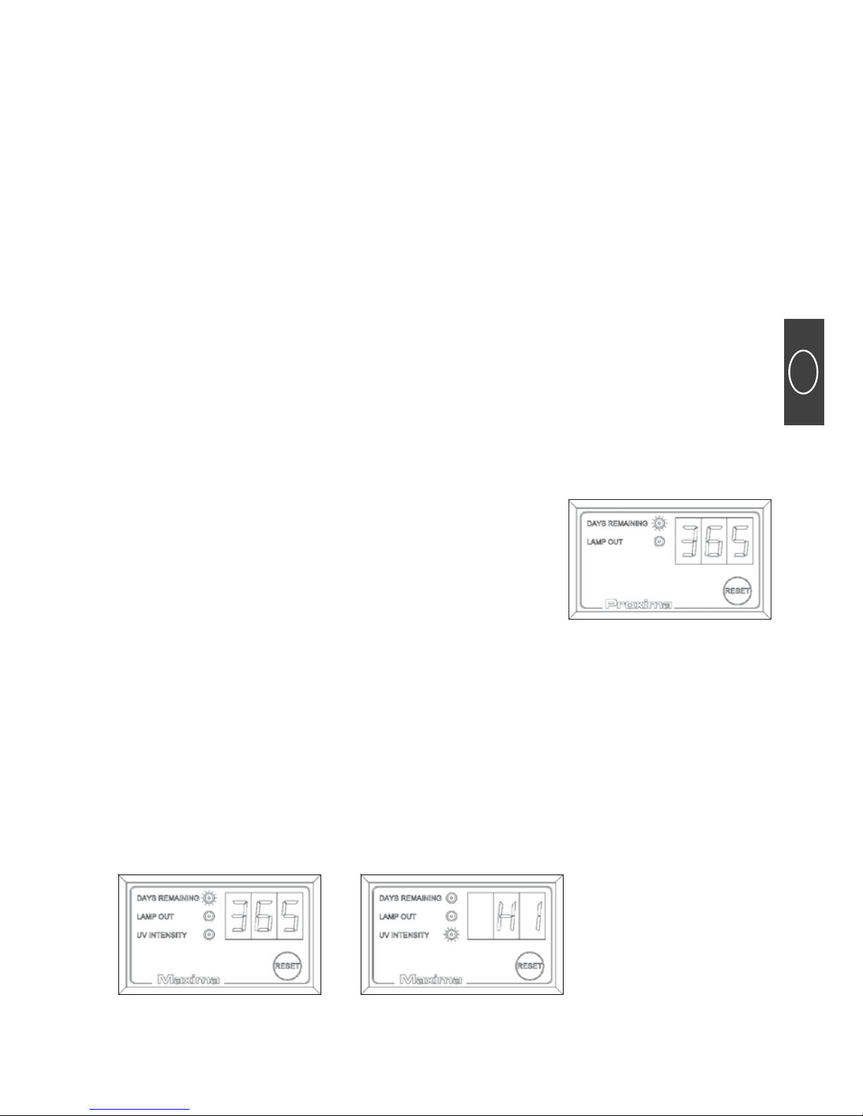
• Commission UV system. Insert plug into socket. The display shows:
3. Commissioning
Sample Proxima
13
GB
Page 14
• Press Reset button for approx. 10 seconds after having switched on the unit, until
you hear a signal
• The unit is now in the warm up phase. After 5 minutes the solenoid valve is
switched on and fully opened.
• Now open the stop valve slowly but completely. At the same time a water tap is
to be opened to ensure that the rest of the air escapes from the unit.
3.1.1. Units without Solenoid Valve
• Open a water tap
• Open slowly the main water tap of the domestic water supply plant until the air
has completely escaped from the unit
• Insert the mains plug into the socket. The display of the Proxima and Maxima unit
shows 365 days
• Press the Reset button for approx. 10 sec. after switching on (Proxima, Maxima)
• Now the unit is in the warming up phase. After 5 minutes it has reached the
highest intensity and is ready for use.
The function control of the Altima units can be seen through the
blue shiny cap.
All UV systems must only be switched on after the reactor has been filled
with water.
14
Page 15

3.2. Tightness Test
4. Software
The Aquada units (Proxima & Maxima) are equipped with a monitoring unit which
is controlled by a micro-controller. The Aquada unit (Altima) is equipped with an
visual function control (section 3.1.1.)
• After first commissioning 365 is shown on the display and the LED „days of use“
is lit up (Proxima, Maxima)
• Press the RESET button for approx. 10 sec. (directly after switching on)
• The initialization time is 5 minutes
• After this the unit is ready for operation and the outlet solenoid valve is switched
on
• The display of the Maxima version now changes every 2 seconds from the display
of the days of use to the display of the UV intensity. The Proxima display remains
showing the days of use. In normal rating operation, the intensity is shown by HI
in the display.
• The display always shows the remaining number of days of use
After commissioning, all screw connections are to be checked
for tightness.
ITT Water & Wastewater do not assume any responsibility for
water damage(s)!
15
GB
Page 16

4.1. Alarm Messages
Thefollowingalarmmessagescanoccurduringoperation:
AL1 » UV lamp failed
AL2 » UV intensity less than 55 % of set value
AL3 » End of lamp life (days of use = 0)
AL4 » UV intensity between 55 % and 70 % of set value
AL5 » UV lamp life < 30 days of use
Alarm 1
• UV lamp has not ignited
• UV lamp is defect
• Lamp failure LED is lit up
» Check plug connection of UV lamp
» Remove transparent cap as described and fit it once more
» Insert new UV lamp
» Have ballast checked by authorized service technician
Alarm 2
• Quartz sleeve is dirty
• Sensor is dirty
• End of UV lamp life (due to frequent switching on and off)
• Unit has been operated too long without flowing water (reactor is heated up)
• Lamp filament wiring is in front of the sensor window
» Disassemble quartz sleeve as described in section 2.1.2.1. and clean with a cleaner
» Disassemble sensor and clean sensor window
» Avoid frequent switching on and off, as the unit has been designed for
continuous operation
» Switch unit off and let it cool down
» Turn transparent lamp connector by 45°
Alarm 3
• End of UV lamp life
» Install new lamp (Use only original WEDECO spare parts)
16
Page 17

Alarm 4
• Normal UV lamp ageing (disinfection is still given)
• Cleaning could be required soon
• Lamp filament wiring is in front of the sensor window
» Normal operating conditions can be restored by cleaning the unit
» In the display „HI“ is replaced by „LO“ (only Maxima)
» Turn transparent lamp connector by 45°
Alarm 5
• End of lamp life in 30 days
» Order new UV lamp
4.2. New Start after Replacement of UV Lamp
The quartz sleeve and sensor should be cleaned
after each replacement of the UV lamp. The reactor
should be cleaned when necessary.
For the new start of the system proceed in the same
way as for first commissioning. When you press the
RESET button (press for 10 sec.), directly after switching on, the day counter is reset to 365 and the
unit is newly initialized.
All alarm messages are also given acoustical. The acoustical signal can be
reset by pressing the RESET button.
17
GB
Page 18

5. Exploded Diagram
1 » control box
2 » reactor
3 » quartz sleeve
4 » UV lamp
5 » head piece
6 » O-ring (head piece)
7 » lamp connection
8 » O-ring (quartz sleeve)
9 » UV sensor
10 » sensor connection
11 » control fastening band
12 » reactor fastening band
13 » reactor fastening band
18
Page 19

6. Spare Parts List
Spare Part No. Description
760054 Control Box AQUA 1 Altima
760055 Control Box AQUA 2 & 4 Altima
760056 Control Box AQUA 7 & 10 Altima
760057 Control Box AQUA 1 Proxima
760058 Control Box AQUA 2 & 4 Proxima
760059 Control Box AQUA 7 & 10 Proxima
760060 Control Box AQUA 1 Maxima
760061 Control Box AQUA 2 & 4 Maxima
760062 Control Box AQUA 7 & 10 Maxima
703321 Quartz sleeve 25 x 1,3 x 360 (inc. seal)
703322 Quartz sleeve 25 x 1,3 x 560 (inc. seal)
703323 Quartz sleeve 25 x 1,3 x 910 (inc. seal)
37085 UV Lamp NLR 1825 WS (Aquada 1)
37086 UV Lamp NLR 1845 WS (Aquada 2 & 4)
37087 UV Lamp NLR 1880 WS (Aquada 7 & 10 )
36538 Head piece
Ø 48 x 40 PBT Crastin S 600
35492 O-Ring 24,77 x 5,33 FPM
37126 Assembly Lamp cable Ölflex 5 x 0,75 mm² 1,5 m
703324 Assembly Sensor window 18 x 2 (inc. Seal)
37250 Assembly UV Sensor (inc. Seal)
38127 power cord swiss
37155 power cord european
37156 power cord italian
36944 power cord british
36623 Reactor R1 (304)
36622 Reactor R2 (304)
36621 Reactor R4 (304)
36620 Reactor R7 (316 L)
36619 Reactor R10 (316 L)
36628 Reactor (Sensor) R1 (304)
36627 Reactor (Sensor) R2 (304)
36626 Reactor (Sensor) R4 (304)
36625 Reactor (Sensor) R7 (316 L)
36624 Reactor (Sensor) R10 (316 L)
37360 Face Spanner
37361 Torque-controlled Spanner „Slipper“ 2 - 10 Nm
19
GB
Page 20

Page 21

21
WEDECO Aquada
GB
DE
F
Installation and Maintenance Instructions
Installations- und Wartungsanleitung
Notice d’installation et de Maintenance
I
Istruzioni di Installazione e Manutenzione
Page 22

Inhalt
1. Allgemeines&Anwendungen
2. MontageundInstallation
2.1. Reaktor
2.1.1. Montage des Reaktors
2.1.2. Einbau des Quarzrohres und des UV-Strahlers
2.1.2.1. Säubern und Austauschen des Quarzrohres
2.1.2.2. Anbringen des UV-Sensors (nur Maxima)
2.1.3. Wasseranschlüsse herstellen
2.2. Steuerung
2.2.1. Montage der Steuerung
2.2.2. Elektrische Anschlüsse
2.2.3. Anschluss des UV-Strahlers
3. Inbetriebnahme
3.1. Geräte mit Magnetventil
3.1.1. Geräte ohne Magnetventil
3.2. Dichtigkeitsprüfung
4. Software
4.1. Fehlermeldungen
4.2. Neustart nach Tausch des UV Strahlers
5. Explosionszeichnung
6. Ersatzteilliste
7. EG-Konformitätserklärung(Seite82)
ACHTUNG:
Bitte lesen Sie dieses Handbuch sorgfältig und befolgen Sie die darin
gegebenen Hinweise. Die Installation darf nur von autorisierten Fachleuten
durchgeführt werden.
22
Page 23

1. Allgemeines & Anwendungen
Die Desinfektion mittels ultraviolettem Licht (UV) ist ein wirksames, wirtschaftliches
und besonders umweltfreundliches Verfahren.
UV-Licht tötet pathogene Mikroorganismen innerhalb von Sekunden ohne Rückstände, schädliche Nebenprodukte oder Geruchs- und Geschmacksbeeinträchtigungen. Eine Gefährdung des Betriebspersonals durch den Umgang mit gesundheitsschädlichen Chemikalien ist dadurch ebenfalls ausgeschlossen.
Die Wirkungsweise des UV-Lichts wird durch den Einsatz besonders effektiver UV-C
Strahlung (254 Nm) genutzt. Sie bewirkt eine sekundenschnelle, photochemische
Reaktion in der für alle Mikroorganismen lebensnotwendigen DNS (Desoxyribonucleinsäure). Dadurch wird der Mikroorganismus entweder abgetötet oder seine
Vermehrungsfähigkeit zerstört.
Die Reduktionsrate ist abhängig von der UV-Mindestbestrahlung (UV-Dosis), das bedeutet der Zeit in der ein Mikroorganismus einer bestimmten UV-Bestrahlungsstärke
(W/m²) ausgesetzt ist. Für die sichere Desinfektion von Trinkwasser wird bei einer
UV-Dosis von 400 J/m² die geforderte Reduktion der wichtigsten humanpathogenen
Bakterien, Parasiten und Viren um 4 Zehnerpotenzen erreicht.
Die Desinfektionsleistung einer UV-Anlage beruht im Wesentlichen darauf, dass
jedes Volumenelement beim Durchströmen des UV-Reaktors die notwendige UVDosis erhält. Um dies zu gewährleisten, sind Bestrahlungsfeld und Hydraulik in der
UV-Anlage optimal aufeinander abgestimmt.
Die UV-Bestrahlung von Trinkwasser führt bei den zur Desinfektion eingesetzten
UV-Dosiswerten zu keinen unerwünschten Nebenreaktionen. Da dem Wasser durch
die UV-Bestrahlung keine desinfektionswirksame Substanz zugesetzt wird, ist nach
Passieren des UV-Reaktors keine Depotwirkungen vorhanden.
ACHTUNG:
Nur bei Verwendung von orginal WEDECO Ersatzteilen (Strahler,
EVG, usw.) kann die Funktion (Desinfektionsleistung) sichergestellt werden.
Bei Fragen wenden Sie sich an:
www.wedeco.com
Tel.: +49 (0) 5221 930-777
Fax : +49 (0) 5221 930-196
23
DE
Page 24

Allgemeine Sicherheitshinweise
ELEKTROSCHOCK!
Achtung gefährliche elektrische Spannung. Die Nichtbeachtung dieses
Hinweises kann zu schwerwiegenden körperlichen Schäden führen.
EIN AUGENSCHUTZ IST ZU TRAGEN!
WICHTIG!
Hinweis auf einen nützlichen Tipp oder eine andere Information.
VORSICHT!
UV-C Strahlung ist schädlich für Augen und Haut! UV-Lampen dürfen nur
in der Strahlungskammer benutzt werden, wenn geeignete Schutzabdeckungen angebracht sind. Personen sollten niemals der UV-C Strahlung
ausgesetzt werden.
• Verwenden Sie dieses Desinfektionsgerät nur für den vorgesehenen Zweck wie in
der Betriebsanleitung beschrieben. Die Verwendung von Zusatzgeräten, die nicht
von ITT Water & Wastewater empfohlen oder vertrieben werden, können einen
unsicheren Zustand hervorrufen.
• Dieses Desinfektionsgerät ist vor Gebrauch ordnungsgemäß und in Übereinstimm ung mit der Betriebsanleitung zu installieren.
• Betreiben Sie kein Gerät, das eine beschädigte Anschlussleitung oder Stecker hat,
das Fehlfunktionen aufweist oder fallengelassen oder auf irgendeine Weise
beschädigt wurde.
• Der Stecker eines Gerätes, das nicht in Gebrauch ist, muss stets aus der Steck dose entfernt werden, bevor Teile angebracht oder abgenommen werden oder
das Gerät gereinigt wird. Ziehen Sie das Desinfektionsgerät niemals an der An schlussleitung aus der Steckdose. Fassen Sie den Stecker fest an und ziehen Sie
diesen direkt aus der Steckdose.
24
Page 25

• Das UV-Desinfektionsgerät ist immer vom Stromkreis zu trennen bevor:
A. Irgendwelche Reparaturen durchgeführt werden
ANMERKUNG:
Wirempfehlendringend,dassjeglicheWartungsarbeitendurchqualifi ziertesFachpersonalausgeführtwird.
B. Eine Reinigung durchgeführt wird
C. Der Austausch des UV-Strahlers vorgenommen wird
• Vor Wartungsarbeiten das Gerät immer drucklos machen.
• Den UV-Strahler nicht außerhalb des UV-Desinfektionsgerätes betreiben.
UV-Anlagen, die mit Magnetventil ausgestattet sind dürfen nicht
längere Zeit (max. 48 Stunden) ohne Wasserdurchfluss betrieben
werden. Bei längerer Abwesenheit ist die Anlage außer Betrieb
zu nehmen.
Die WEDECO UV-Strahler sind für den Dauerbetrieb ausgelegt
und erreichen dann ihre größte Desinfektionsleistung.
Häufiges Ein- und Ausschalten vermindert deutlich die Lebensdauer des UV-Strahlers!
Maximal 200 Schaltvorgänge!
25
DE
Page 26

2. Montage und Installation
Vor der Installation sind folgende Punkte sicherzustellen:
• Der max. Betriebsdruck von 1000 K Pa (10 bar) darf nicht überschritten werden
• Die max. Umgebungstemperatur beträgt 40° C
• Die max. Wassertemperatur beträgt 25° C
• Die max. Durchflussmenge darf nicht überschritten werden (siehe 2.1. Reaktor)
• Der Einbauort des Reaktors und der Steuerung muss frostfrei und trocken sein.
2.1. Reaktor
Folgende Reaktortypen sind in der Aquada-Serie erhältlich:
*
Durchfluss: 400 J/m2, UV-Transmission: 94 %
Bei der Montage und Installation sind die landesüblichen Normen und Vorschriften einzuhalten. Die Installation darf nur von
Fachkräften durchgeführt werden.
Typ Länge Durchmesser Anschlüsse
„
Min. Freiraum
oberh. des Reaktors
Max. Durchfluss*
m
3
/h
1 470 mm 70 mm R 1/2 370 mm 0,70
2 670 mm 70 mm R 3/4 570 mm 1,77
4 670 mm 101,6 mm R 3/4 570 mm 3,01
7 1030 mm 101,6 mm R1 920 mm 6,20
10 1030 mm 140 mm R1 1/2 920 mm 9,00
26
Page 27

2.1.1. Montage des Reaktors
• Stellen Sie bitte vor dem Einbau sicher, welchen Reaktortyp sie verwenden.
(Informationen über den Reaktortyp finden Sie auf dem Typenschild)
• Es ist sicherzustellen, dass sich genügend Freiraum oberhalb des Reaktors befindet
(Maße siehe Tabelle 2.1. Reaktor), da sonst das Einsetzen des UV-Strahlers und
die Wartung der Anlage nicht möglich sind.
• Der Reaktor ist mit den beiliegenden Montageschellen auf der Wand oder einem
anzufertigenden Gestell zu befestigen.
• Bei Geräten mit UV-Sensor ist nur eine vertikale Montage des Reaktors zulässig.
• Der Reaktor ist frostsicher zu montieren.
• ITT Water & Wastewater empfiehlt den Reaktor mit einer Metallleitung anzu schließen (Kupfer, Stahl) Kunststoffleitungen müssen aus UV beständigem
Material sein!
Strahleranschluss
Auslauf
UV Sensor
Steuerung
Zulauf
27
DE
Page 28

2.1.2. Einbau des Quarzrohres und des UV-Strahlers
Der Reaktor wird mit eingebautem Quarzrohr geliefert. Das schwarze Kopfstück, in
das der UV-Strahler eingeführt wird, ist mit 5 Nm werksseitig verschraubt worden.
EinbauUV-StrahlersiehePunkt2.2.3.
2.1.2.1. Säubern und Austauschen des Quarzrohres
Der transparente Stecker des Strahleranschlusses ist durch leichtes drehen nach
links oder rechts (bis auf die Erhöhung im Kopfstück) abzuziehen.
Den UV-Strahler durch Drücken der beiden transparenten Rastfahnen aus dem
Reaktor entfernen. Kopfstück aus dem Reaktor rausdrehen und dann vorsichtig
mit dem Quarzrohr entfernen. (BeideTeilefesthalten)
Anschließend den Belag mit einem feuchten Tuch (ggf. Reiniger verwenden) vom Quarzrohr
entfernen und im sauberen, trockenen Zustand wieder einbauen.
Das Quarzrohr und das Kopfstück sind zwei Einzelteile. Beim
Ausbau beide Teile festhalten, da sonst das Quarzrohr aus dem
Kopfstück rutschen könnte!
Reaktor
O-ring
O-ring
Strahler Rückführung
Quarzrohr
Kopfstück Rastfahnen
UV-Strahler
28
Page 29

Montageanleitung
Richtig eingebauter Strahler
Anschluss!
Der UV-Strahler ist ebenfalls
vor dem Einbau mit einem
trockenen Tuch zu säubern.
Er wird von oben durch das
Kopfstück geführt, bis die
beiden transparenten Rastfahnen des Anschlusssteckers im Kopfstück einrasten.
Nach dem Einsetzen des UVStrahlers ist der transparente
Strahleranschlussstecker auf
das Kopfstück aufzustecken
bis er einrastet.
(AufFührungimStecker
achten)
Falsch eingebauter Strahler
Anschluss!
Kopfstück UV Strahler
Stecken Sie den Steck er
richtig auf das Kopfstück
(Achten Sie auf die Führung)
Stecken Sie den Anschlussstecker auf, bis er einrastet.
UV-Strahler
Transparenter
Strahleranschluss
Kopfstück
Transparenter Strahleranschlussstecker
29
DE
Page 30

2.1.2.2. Anbringen des UV-Sensors
Der UV-Sensor ist werksseitig an der Steuerung angebracht (nur Maxima). Er muss
lediglich an den Reaktor geschraubt werden. Die Verschraubung darf nicht mit
schwerem Werkzeug erfolgen. Der Sensor sollte handfest (ca. 5 Nm) angezogen
werden. Bei Missachtung kann es zur Zerstörung der im Sensor befindlichen Quarzglasscheibe kommen.
Zur Reinigung darf die Quarzglasscheibe, die sich im Sensor befindet, nicht ausgebaut werden, da es sonst zur Zerstörung des Quarzglases kommen kann! Sie sollte
lediglich mit einem weichen, sauberen Tuch gereinigt werden.
2.1.3. Wasseranschlüsse herstellen
• Bei den Wasseranschlüssen ist darauf zu achten, dass am Zu- und Ablauf des
Reaktors Absperrvorrichtungen angebracht werden, da diese die Wartungs arbeiten erleichtern
• Für die Wasseranschlüsse ist UV beständiges Material zu verwenden. Anschluss größen entnehmen Sie bitte der Tabelle unter 2.1. Reaktor.
• Die Wasseranschlüsse sind gemäß den geltenden Vorschriften durchzuführen
• Es wird optional ein Magnetventil angeboten (Proxima, Maxima), welches den
Durchfluss bei Ausfall der Versorgungsspannung sowie zu geringer UV-Intensität
im Reaktor verhindert
UV-Sensor
HINWEIS:
Der Sensor ist abhängig von der Wasserbeschaffenheit in regelmäßigen
Intervallen zu reinigen. Dazu Sensor im druck und wasserlosen Zustand
abschrauben und die Quarzscheibe reinigen.
30
Page 31

2.2. Steuerung
Es sind folgende Ausstattungsvarianten erhältlich:
1.Altima
• Optische Funktionskontrolle des UV-Strahlers durch transparenten Strahleran schluss
• leicht zu befestigende Steuerung (Wand oder Reaktormontage)
2.Proxima
• Zusätzlich zum Umfang der Altima-Variante
• Anschlussmöglichkeit eines Magnetventils, das einen Durchfluss nur bei einge schaltetem UV Strahler zulässt
• Steuerung des Magnetventils durch einen Microcontroler
• Displayanzeige der verbleibenden Lebensdauer des
UV-Strahlers
• Optisch und akustischer Alarm bei Strahlerausfall
3.Maxima
• Zusätzlich zum Steuerumfang der Proxima-Variante
• Ein UV-Sensor, der ständig die Intensität überwacht und bei Unterschreiten der
min. Intensität das Magnetventil schaltet und einen optischen und akustischen
Alarm herausgibt. Intensität wird im Display angezeigt.
31
DE
Page 32

2.2.1. Montage der Steuerung
Die Steuerung kann mit den mitgelieferten Befestigungsbändern direkt am Reaktor
befestigt werden.
• Eine Wandmontage ist ebenfalls möglich. Hierbei sind zwei Löcher zu bohren
(Lochabstand 134 mm) und mit Dübeln und Schrauben zu versehen. Dann lässt
sich das Steuergehäuse mit den dafür vorgesehenen Löchern auf die Schrauben
einhängen.
• Bei einer Wandmontage ist auf die mitgelieferten Leitungslängen zu achten:
» Netzanschlussleitung: 200 cm
» Sensorleitung: 150 cm (nur Maxima)
» Strahleranschluss: 150 cm
» Magnetventilleitung: 150 cm (Optional)
2.2.2. Elektrische Anschlüsse
Befestigungsbänder durch die
Ge häuse-Öffnung ziehen und fest
am Reaktor befestigen.
Eine Auftrennung oder Verlängerung der Leitungen ist nicht
zulässig!
Beim Anschluss der Steuerung sind die national geltenden Vorschriften, sowie die Angaben auf dem Typenschild einzuhalten
(Netzspannung, Frequenz, etc.). Das Gerät ist nur an Netzformen
zu betreiben , die einen Schutzleiter (PE) beinhalten. Die Installationsarbeiten sind nur von Elektrofachkräften durchzführen. Bei
Arbeiten am Gerät ist grundsätzlich der Netzstecker zu ziehen.
Die elektrischen Anschlussdaten entnehmen Sie bitte dem Typenschild auf dem Gerät.
Der Potentialausgleichsleiter (Erde) ist am Reaktor anzuschließen!
Das Öffnen des Steuerghäuses führt zum Verlust der Garantie!
32
Page 33

2.2.3. Anschluss des UV Strahlers
• Der UV-Srahler ist aus der Verpackung zu entfernen und mit einem sauberen
Tuch abzuwischen (nicht mit den Fingern auf den Strahler fassen)
• Den Strahler in das Kopfstück einführen bis die transparenten Rastfahnen des
Strahlersteckers im Kopfstück einrasten. (Rastnasen beim Einführen mit zwei
Fingern leicht eindrücken; siehe Bild 1, Seite 32)
• Es muß beim Einführen des UV-Strahlers darauf geachtet werden, dass die Rück führungen (siehe Bild 1, Seite 32) das Sensorsignal nicht schwächen. Sie dürfen
nicht vor dem Sensorfenster verlaufen.
Vor der Inbetriebnahme sollten alle wichtigen Punkte der Bedienungsanleitung nochmals überprüft werden.
3.1. Geräte mit Magnetventil
• Das Kopfstück zwei Umdrehungen lösen
• Den Absperrhahn der Hauswasseranlage leicht öffnen
• Durch das Kopfstück entweicht Luft. Das Kopfstück solange geöffnet lassen bis
Wasser austritt. Dann das Kopfstück wieder fest verschließen.
Achtung Spritzwasser!
• Die UV-Anlage in Betrieb nehmen. Den Netzstecker in die Steckdose stecken.
Das Display zeigt (Beispiel Maxima):
3. Inbetriebnahme
Anzeige nach der Inbetriebnahme des Gerätes.
Nach 5 Minuten wechselt
das Gerät zwischen beiden
Anzeigen.
33
DE
Page 34

• Den Reset Button nach dem Einschalten ca. 10 sek. gedrückt halten bis ein Signal ton zu hören ist
• Das Gerät befindet sich nun in der Aufwärmphase. Nach 5 Minuten wird das
Magnetventil eingeschaltet und hat nun vollen Durchfluss.
• Nun den Absperrhahn langsam ganz öffnen. Gleichzeitig ist ein Wasserhahn zu
öffnen, um die restliche Luft aus dem Gerät zu bekommen.
3.1.1. Geräte ohne Magnetventil
• Es ist eine Wasserentnahmestelle zu öffnen
• Den Haupthahn der Hauswasseranlage langsam öffnen bis die gesamte Luft aus
dem Gerät entwichen ist
• Den Netzstecker in die Steckdose stecken. Die Geräte Proxima und Maxima zeigen
beide 365 Tage im Display.
• Den Reset Button nach dem Einschalten ca. 10 sek. gedrückt halten bis ein Signal ton zu höhren ist (Proxima, Maxima)
• Das Gerät befindet sich nun in der Aufwärmphase und hat nach 5 Minuten die
höchste Intensität erreicht und ist voll einsatzfähig
Bei den Altima Geräten ist die
Funk tionskontrolle des UVStrah lers nur durch die blau
schimmernde Anschlusskappe
zu sehen.
Alle UV Anlagen dürfen nur eingeschaltet werden, wenn der Reaktor mit
Wasser gefüllt ist.
34
Page 35

3.2. Dichtigkeitsprüfung
4. Software
Die Aquada-Geräte (Proxima & Maxima) verfügen über eine Mikrokontroler gesteuerte Überwachungseinheit. Das Aquada-Gerät (Altima) verfügt über eine optische
Funktionskontrolle (Punkt 3.1.1.)
• Nach der Erst-Inbetriebnahme erscheint im Display die Anzeige 365 und die LED
„Nutzungstage“ leuchtet. (Proxima, Maxima)
• Der RESET Button ist für 10 sek. zu drücken, bis ein Signalton zu höhren ist
(direkt nach dem Einschalten)
• Die Initialisierungszeit beträgt 5 Minuten
• Danach sind die Geräte betriebsbereit und der Magnetventilausgang wird ge schaltet
• Das Display der Maxima Version wechselt nun im 2 sek. Takt die Anzeige zwischen
Nutzungstage und UV-Intensität. Das Proxima Display verbleibt bei der Anzeige
Nutzungstage. Die Intensität wird im Nennbetrieb durch „HI“ im Display ange zeigt.
• Das Display zeigt immer die noch verbleibenden Nutzungstage an
Nach der Inbetriebnahme sind alle Schraubverbindungen auf
Dichtigkeit zu überprüfen.
ITT Water & Wastewater übernimmt keine Haftung für Wasserschäden!
35
DE
Page 36

4.1. Fehlermeldungen
FolgendeFehlermeldungenkönnenwährenddesBetriebesauftreten:
AL1 » UV-Strahler ausgefallen
AL2 » UV-Intensität unter 55 % des Sollwertes
AL3 » Ende der Strahler Lebensdauer (Nutzungstage = 0)
AL4 » UV-Intensität zwischen 55 % und 70 % des Sollwertes (Display Anzeige „LO“)
AL5 » UV-Strahler Lebensdauer < 30 Nutzungstage
Alarm 1
• UV-Strahler hat nicht gezündet
• UV-Strahler ist defekt
• „Lampenausfall“ LED leuchtet
» Steckverbindung am Strahler überprüfen
» Transparente Kappe wie beschrieben entfernen und nochmals aufstecken
» Neuen UV-Strahler einsetzen
» EVG durch autorisierten Service überprüfen lassen
Alarm 2
• Quarzrohr verschmutzt
• Sensor verschmutzt
• UV-Strahler am Ende der Lebensdauer (durch häufiges Ein & Ausschalten)
• Gerät zu lange ohne Wasserdurchfluss betrieben (Reaktor heizt sich auf)
• Strahlerrückführung verläuft vor dem Sensorfenster
» Quarzrohr wie beschrieben (Ab.: 2.1.2.1.) ausbauen und mit Reiniger reinigen
» Sensor ausbauen und Sensorscheibe reinigen
» Häufiges Ein- & Ausschalten vermeiden. Gerät ist für Dauerbetrieb ausgelegt.
» Gerät ausschalten und abkühlen lassen
» Transparenten Strahleranschlussstecker um 45° drehen
Alarm 3
• UV-Strahler am Ende der Lebensdauer
» Neuen UV-Strahler einbauen (Nur orginal WEDECO Ersatzteile verwenden)
36
Page 37

Alarm 4
• Normale UV-Strahler Alterung (Entkeimung ist noch gegeben)
• Eine Reinigung kann bald erforderlich sein
• Strahlerrückführung verläuft vor dem Sensorfenster
» Durch die Reinigung des Gerätes wird der Normale Betriebszustand wieder er reicht
» Die Displayanzeige „HI“ wird durch „LO“ ersetzt (nur Maxima)
» Transparenten Strahleranschlussstecker um 45° drehen
Alarm 5
• Ende der Strahlernutzungsdauer in 30 Tagen
» Neuen UV-Strahler bestellen
4.2. Neustart nach Tausch des UV-Strahlers
Bei jedem Tausch des UV Strahlers sollten auch das
Quarzrohr und der Sensor gereinigt werden. Der
Reaktor sollte nach Bedarf einer Reinigung unterzogen werden.
Beim Neustart der Anlage ist wie bei der ersten Inbetriebnahme zu verfahren. Durch das Betätigen des
Reset Buttons (10 sek. gedrückt halten) direkt nach
dem Einschalten wird der Tageszähler wieder auf
365 gesetzt und das Gerät wird neu initialisiert.
Alle Alarm-Meldungen werden auch akustisch wiedergegeben. Der Signalton lässt sich durch betätigen des RESET Buttons zurücksetzen.
37
DE
Page 38

5. Explosionszeichnung
1 » Steuerung
2 » Reaktor
3 » Quarzrohr
4 » UV-Strahler
5 » Kopfstück
6 » O-Ring (Kopfstück)
7 » Strahleranschluss
8 » O-Ring (Quarzrohr)
9 » UV-Sensor (Maxima)
10 » Sensor Befestigung
11 » Befestigung Steuerung
12 » Reaktor Befestigung
13 » Reaktor Befestigung
38
Page 39

6. Ersatzteilliste
Ersatzteil-Nr. Ersatzteil-Bezeichnung
760054 Baugr. Schaltkasten AQUA 1 Altima
760055 Baugr. Schaltkasten AQUA 2 & 4 Altima
760056 Baugr. Schaltkasten AQUA 7 & 10 Altima
760057 Baugr. Schaltkasten AQUA 1 Proxima
760058 Baugr. Schaltkasten AQUA 2 & 4 Proxima
760059 Baugr. Schaltkasten AQUA 7 & 10 Proxima
760060 Baugr. Schaltkasten AQUA 1 Maxima
760061 Baugr. Schaltkasten AQUA 2 & 4 Maxima
760062 Baugr. Schaltkasten AQUA 7 & 10 Maxima
703321 Baugr. Quarzglasrohr 25 x 1,3 x 360 (inkl. Dichtung)
703322 Baugr. Quarzglasrohr 25 x 1,3 x 560 (inkl. Dichtung)
703323 Baugr. Quarzglasrohr 25 x 1,3 x 910 (inkl. Dichtung)
37085 UV-Strahler NLR 1825 WS (Aquada 1)
37086 UV-Strahler NLR 1845 WS (Aquada 2 & 4)
37087 UV-Strahler NLR 1880 WS (Aquada 7 & 10)
36538 Kopfstück
Ø 48 x 40 PBT Crastin S 600
35492 Runddichtring 24,77 x 5,33 FPM
37126 Konfektionierung Leitung Ölflex 5 x 0,75 mm² 1,5 m
703324 Baugruppe Sensorquarzglasscheibe (inkl. Dichtung)
37250 Baugruppe UV-Sensor (inkl. Dichtung)
38127 Anschlußleitung schweizerisch
37155 Anschlussleitung europäisch
37156 Anschlussleitung Italienisch
36944 Anschlussleitung britisch
36623 Reaktorgehäuse R1 (304)
36622 Reaktorgehäuse R2 (304)
36621 Reaktorgehäuse R4 (304)
36620 Reaktorgehäuse R7 (316 L)
36619 Reaktorgehäuse R10 (316 L)
36628 Reaktorgehäuse (Sensor) R1 (304)
36627 Reaktorgehäuse (Sensor) R2 (304)
36626 Reaktorgehäuse (Sensor) R4 (304)
36625 Reaktorgehäuse (Sensor) R7 (316 L)
36624 Reaktorgehäuse (Sensor) R10 (316 L)
37360 Stirnlochschlüssel 35 mm
37361 Drehmomentschlüssel „Slipper“ 2 - 10 Nm
39
DE
Page 40

40
Page 41

41
WEDECO Aquada
GB
DE
F
Installation and Maintenance Instructions
Installations- und Wartungsanleitung
Notice d’installation et de Maintenance
I
Istruzioni di Installazione e Manutenzione
Page 42

Sommaire
1. Généralitésetapplications
2. Montageetinstallation
2.1. Réacteur
2.1.1. Montage du Réacteur
2.1.2. Installation de la gaine de quartz et de la lampe UV
2.1.2.1. Nettoyage et remplacement de la gaine de quartz
2.1.2.2. Mise en place du capteur UV
2.1.3. Raccordement au circuit d’eau
2.2. Systèmedecommande
2.2.1. Montage du boîtier de commande
2.2.2. Branchements électriques
2.2.3. Mise en place de la lampe UV
3. Miseenservice
3.1. Système avec électrovanne
3.1.1. Système sans électrovanne
3.2. Contrôle d‘étanchéité
4. Logiciel
4.1. Messages d‘alarme
4.2. Nouvelle mise en service après le remplacement de la lampe UV
5. Vueéclatée
6. Listedespiècesderechange
7. Déclarationdeconformité(page82)
ATTENTION:
Lisez soigneusement cette notice et conformez-vous aux instructions
qu’elle contient. L’installation ne peut être effectuée que par des techniciens qualifiés.
42
Page 43

1. Généralités et applications
La désinfection de l’eau par la lumière ultraviolette (UV) est un procédé efficace,
économique et particulièrement respectueux de l’environnement.
La lumière UV détruit les micro-organismes pathogènes en quelques secondes sans
laisser de résidus, de sous-produits nocifs et sans altérer l’odeur et le goût de l’eau.
Les opérateurs n’ont pas à manipuler des produits chimiques dangereux.
L’effet de la lumière ultraviolette est particulièrement efficace à la longueur d’onde
de 254 Nm. En quelques secondes elle provoque une réaction photochimique dans
l’acide désoxyribonucléique (ADN), vital pour tous les micro-organismes. Ces microorganismes sont soit détruits, soit empêchés de proliférer.
Le taux de destruction dépend de la dose d’exposition UV, c’est-à-dire du temps
d’exposition d’un micro-organisme à une certaine intensité de rayonnement UV (W/
m²). À une dose UV de 400 J/m² , les virus et les agents pathogènes les plus importants sont réduits de 4 « unités log », ce qui correspond aux normes internationales
et garantit une désinfection sûre.
Les performances de désinfection d’un système UV reposent essentiellement sur le
fait que chaque unité de volume traversant le réacteur UV reçoit la dose UV nécessaire. Pour cela, on a optimisé le champ de rayonnement et les propriétés hydrauliques du système UV.
L’irradiation de l’eau potable par les ultraviolets ne provoque aucune réaction secondaire indésirable aux doses UV que nous utilisons pour la désinfection.
Comme nous n’ajoutons pas de désinfectant à l’eau, il n’y a pas de dépôt après le
passage du volume unitaire dans le réacteur UV.
ATTENTION:
Une désinfection correcte ne peut être garantie que si des pièces de rechange WEDECO d’origine (lampes, ballasts, etc.) sont
utilisées.
Pour toute question, contactez:
www.wedeco.com
Tel.: +33 (0) 1 49 90 01 40
Fax : +33 (0) 1 49 90 01 41
43
F
Page 44

Consignes générales de sécurité
RISQUE D’ÉLECTROCUTION!
Attention – tension électrique dangereuse. Le non-respect de cette consigne peut entraîner des blessures graves.
UNE PROTECTION OCULAIRE EST INDISPENSABLE!
IMPORTANT!
Conseils utiles ou autres informations.
ATTENTION!
Le rayonnement UV-C est dangereux pour les yeux et pour la peau !
N’utilisez les lampes UV que dans la chambre d’irradiation et seulement si
des dispositifs de protection appropriés sont en place.
Les personnes ne doivent jamais être exposées aux rayonnements UV-C.
• Veillez à ce que cet appareil de désinfection ne soit utilisé que dans le but prévu,
conformément à la notice d’utilisation. L’utilisation d’appareils supplémentaires
qui n’ont pas été recommandés ni vendus par WEDECO peut nuire à la sécurité.
• Cet appareil de désinfection doit être installé correctement avant son utilisation
conformément à la notice
• N’utilisez pas l’appareil si le câble ou la prise électrique est en mauvais état, s’il
fonctionne incorrectement ou s’il a subi des dommages quelconques
• Veillez à ce que l’appareil soit débranché lorsqu’il n’est pas en service avant de
démonter ou de remonter des pièces ou avant de le nettoyer. Ne débranchez pas
le câble d’alimentation secteur en tirant dessus : sortez la fiche directement de la
prise de courant.
44
Page 45

• Vérifiez l’isolement électrique de l’appareil de désinfection avant d’effectuer les
opérations suivantes:
A. Préparation
REMARQUE:
Nousrecommandonsdeconfierlesopérationsdemaintenanceàdes
personnesqualifiées.
B. Nettoyage
C. Remplacement de la lampe UV
• Avant toute opération d’entretien, dépressurisez l’appareil
• N’utilisez pas la lampe UV à l’extérieur du réacteur UV
Les systèmes UV équipés d’une électrovanne ne doivent pas être
utilisés sans débit d’eau pendant une période prolongée (48
heures maximum).
Sinon, le système doit être arrêté.
Les lampes UV WEDECO ont été conçues pour atteindre leur
meilleure capacité de désinfection en service continu.
Des cycles marche-arrêt fréquents abrègent la durée de vie de la
lampe UV!
Max . 200 opérations de commutation!
45
F
Page 46

2. Montage et installation
Effectuez les vérifications suivantes avant l’installation:
• Il ne faut pas dépasser une pression de service maximal de 1000 KPa
• La température ambiante maximale est de 40° C
• La température maximale de l’eau est de 25° C
• Le débit maximal ne doit pas être dépassé (voir paragraphe 2.1.)
• Le site d’installation du réacteur doit être sec et à l’abri du gel
2.1. Réacteur
Les types de réacteurs suivants sont disponibles pour la série AQUADA:
*
pour une transmittance UV (à 254 Nm sur 10 mm) de 94% et une dose UV délivrée de 400 J/m²
Attention de respecter les normes et règles nationales pour
le montage et l’installation. L’installation doit être effectuée
uniquement par des techniciens qualifiés.
Type Longueur Diamètre Raccords Espace libre minimal
au-dessus du réacteur
Débit maxi*
m
3
/h
1 470 mm 70 mm R 1/2 370 mm 0,70
2 670 mm 70 mm R 3/4 570 mm 1,77
4 670 mm 101,6 mm R 3/4 570 mm 3,01
7 1030 mm 101,6 mm R1 920 mm 6,20
10 1030 mm 140 mm R1 1/2 920 mm 9,00
46
Page 47

2.1.1. Montage du Réacteur
• Avant l’installation, vérifiez le type de réacteur. (Voir la plaquette signalétique).
• Veillez à ce qu’il y ait assez d’espace libre au-dessus du réacteur (pour les dimen sions, voir paragraphe 2.1.) pour installer la lampe UV et entretenir le système
• Le réacteur doit être fixé à l’aide des pièces de fixation fournies soit au mur, soit
sur un support spécial
• Dans les systèmes comportant un capteur UV, le réacteur doit être monté vertical ement
• Le réacteur monté doit être protégé contre le gel
Lampe UV
Sortie
Capteur UV (facultatif)
Boîtier de commande
Entrée
47
F
Page 48

2.1.2. Installation de la gaine de quartz
et de la lampe UV
Le réacteur est fourni avec une gaine de quartz. La tête de couleur noire qui doit
recevoir la lampe UV a été serrée à un couple de 5 Nm dans notre usine. Avant la
mise en service, vérifiez le serrage de tous les raccords vissés.
Pourl’installationdelalampeUV,voirparagraphe2.2.3.
2.1.2.1. Nettoyage et remplacement de la gaine de quartz
La fiche transparente de la lampe doit être tournée légèrement vers la gauche ou
vers la droite (jusqu’à la partie en relief de la tête), puis retirée.
Retirez la lampe UV du réacteur en pressant les deux pattes transparentes. Dévissez la tête du réacteur, puis sortez-la soigneusement avec la gaine de quartz.
Éliminez les dépôts éventuels de la gaine de quartz et remontez-la après nettoyage.
La gaine de quartz et la pièce de tête sont deux éléments séparés. En cas de démontage, maintenir les deux pièces afin
d‘éviter que la gaine quartz ne se désolidarise de la tête.
Réacteur
Joint torique
Joint torique
Câblage de la lampe
Gaine de quartz
Tête Pattes
Lampe UV
48
Page 49

Notice de montage
Le connecteur transparent de
la lampe doit être correctement clipsé dans la gorge de
la pièce de tête.
La lampe UV doit également être nettoyée avant
sa mise en place. Il faut
l’introduire dans la tête par
le dessus jusqu’à ce que les
deux pattes transparentes
s’enclenchent.
Ce schéma montre que le
connecteur transparent de
lampe a été poussé trop loin.
Pièce de tête noire Lampe UV
Emboîter le capuchon transparent sur l‘épaulement et
encliqueter sur la pièce de
tête.
La connection est bien réalisée. Tourner le capuchon sur
l‘épaulement pour dégager la
connection.
Après la mise en place de la
lampe UV, montez la fiche
transparente sur la tête.
Veillez à ce qu’elle se bloque
correctement en position
(voir le guide dans la prise).
Lampe UV
Connecteur transparent
de lampe
Pièce de têtenoire
Capuchon et connecteur transparent
49
F
Page 50

2.1.2.2. Mise en place du capteur UV
Dans notre usine, le capteur UV a été mis en place (seulement pour le modèle Maxima). Il reste à le visser sur le réacteur. Le serrage doit être effectué uniquement avec
un outil léger. Un couple initial de 5 Nm est suffisant. Attention de ne pas dépasser
ce couple, sinon vous risquez d’endommager le quartz du capteur.
Afin d’éviter toute casse, ne pas retirer la plaque de verre de quartz (situé dans le
capteur) lors du nettoyage. La plaque de verre doit uniquement être nettoyée avec
un chiffon doux et propre.
2.1.3. Raccordement au circuit d’eau
• Pour le raccordement au circuit d’eau, installez des robinets d’arrêt à l’entrée et à
la sortie du réacteur pour faciliter l’entretien
• Un matériau résistant aux UV doit être utilisé pour le raccordement au circuit
d’eau. Pour les dimensions des raccords, reportez-vous au tableau du paragraphe
2.1.
• Le raccordement au circuit d’eau doit être effectué conformément à la réglemen tation nationale
• Une électrovanne est proposée en option (Proxima, Maxima). Elle a pour but de
couper l’eau en cas de panne d’alimentation électrique ou d’intensité UV insuffi sante dans le réacteur.
Capteur
NOTA:
Il faut nettoyer le capteur à intervalles réguliers en fonction de la qualité
de l’eau. Pour ce faire, dévissez le capteur après l’avoir dépressurisé, et
vidé de son eau, puis nettoyez le tube quartz avec le produit de nettoyage.
50
Page 51

2.2. Système de commande
Les variantes d’équipement suivantes peuvent être fournies:
1.Altima
• Contrôle visuel de la lampe UV par le raccord de lampe transparent
• Boîtier de commande facile à fixer (au mur ou sur le réacteur)
2.Proxima
• Comme variante du système Altima
• Possibilité d’installer une électrovanne qui ne laisse s’écouler l’eau que lorsque
l’intensité UV est suffisante
• Commande de l’électrovanne par un microcontrôleur
• Affichage de la durée de vie restante de la lampe
UV sur l’écran
• Alarmes visuelle et sonore en cas de panne de
lampe
3.Maxima
• Comme variante du système Proxima
• Un capteur UV qui contrôle continuellement l’intensité coupe l’alimentation de
l’élecrovanne lorsque l’intensité minimale n’est pas atteinte et émet une alarme
visuelle et sonore. L’intensité est affichée sur l’écran.
51
F
Page 52

2.2.1. Montage du boîtier de commande
Le boîtier de commande peut être monté directement sur le réacteur à l’aide des
colliers fournis.
• Le boîtier de commande peut aussi être fixé au mur. Dans ce cas, percez deux
trous (espacés de 134 mm) et mettez des chevilles et des vis. Vous pouvez ensuite
accrocher la boîte de commande aux vis.
• Dans le cas du montage mural, il faut tenir compte de la longueur des câbles
fournis:
» Câble d’alimentation secteur: 200 cm
» Câble de capteur: 150 cm (pour Maxima seulement)
» Câble de lampe: 150 cm
» Câble d’électrovanne: 150 cm (option)
2.2.2. Branchements électriques
Sortez les colliers par l’ouverture
du boîtier et fixez-les au réacteur.
Les câbles fournis ne doivent être ni raccourcis ni allongés!
Pour le raccordement du boîtier de commande au secteur,
respectez la réglementation nationale en vigueur ainsi que
les indications figurant sur la plaquette signalétique (tension
d’alimentation, fréquence, etc.) L’installation ne doit être effectuée que par des électriciens qualifiés. Avant toute intervention
sur le matériel, débranchez le câble secteur de la prise de courant.
Le câble de mise à la terre doit être connecté au réacteur!
NE PAS OUVRIR le boîtier de commande; cela annulerait la garantie!
52
Page 53

2.2.3. Mise en place de la lampe UV
• Déballez la lampe UV et essuyez-la avec un chiffon propre (ne la touchez pas avec
les doigts)
• Introduisez la lampe dans la tête jusqu’à l’enclenchement des pattes transparen tes (en introduisant la lampe, pressez légèrement les pattes entre deux doigts; voir
figure 1 page 52)
Vérifiez tous les points importants de la notice d’utilisation avant la
mise en service.
3.1. Système avec électrovanne
• Dévissez la tête (deux tours)
• Ouvrez le robinet d’arrêt du circuit d’eau
• L’air s’échappe par la tête. Laissez la tête ouverte jusqu’à ce que de l’eau en sorte.
Rebloquez la tête. Attention aux éclaboussures!
• Mettez le système UV en service. Branchez le câble sur la prise de courant.
L’écran affiche:
3. Mise en service
Sample Proxima
53
F
Page 54

• Appuyer sur le bouton de réinitialisation environ 10 secondes après avoir mis le
système sous tension jusqu’à ce qu’un signal soit audible
• Le système est en phase de préchauffage. Au bout de 5 minutes, l’électrovanne
est sous tension et complètement ouverte.
• Ouvrez le robinet d’arrêt lentement mais complètement. Parallèlement, ouvrez un
robinet d’eau pour que le reste de l’air s’échappe.
3.1.1. Système sans électrovanne
• Ouvrez un robinet d’eau
• Ouvrez lentement le robinet principal du circuit d’eau jusqu’à ce qu’il n’y ait plus
d’air dans le système
• Branchez le câble sur la prise de courant. L’écran du système Proxima ou Maxima
affiche 365 jours
• Appuyez sur le bouton de réinitialisation pendant environ 20 secondes après la
mise sous tension (Proxima, Maxima)
• Le système est en phase de préchauffage. Au bout de 5 minutes, l’intensité est
maximale et le système est prêt à fonctionner.
Le fonctionnement de la lampe
peut être contrôlé à travers le
capuchon transparent.
Tous les systèmes UV ne doivent être mis sous tension uniquement si le
réacteur est rempli d’eau.
54
Page 55

3.2. Contrôle d’étanchéité
4. Logiciel
Les appareils Aquada (Proxima & Maxima) sont équipés d’un système de surveillance piloté par un microcontrôleur. L’appareil Aquada Altima est équipé d’un
contrôle de fonctionnement visuel (paragraphe 3.1.1.)
• Après la mise en service initiale, 365 est affiché sur l’écran et le voyant lumineux
«jours d’utilisation» est allumé (Proxima, Maxima)
• Appuyez sur le bouton de réinitialisation pendant environ 10 secondes
(juste après la mise sous tension)
• Le temps d’initialisation est de 5 minutes
• Le système est alors prêt à fonctionner et l’électrovanne de sortie est sous tension
• L’écran de la version Maxima alterne entre l’affichage des jours d’utilisation et
l’affichage de l’intensité UV à 2 secondes d’intervalle. L’écran de la version Proxi ma affiche en permanence le nombre de jours d’utilisation.
• En fonctionnement normal, l’intensité est indiquée par „HI“ sur l’écran
• L’écran affiche toujours le nombre de jours d’utilisation restants
Après la mise en service, il faut vérifier l’étanchéité de tous les
raccords vissés.
ITT Water & Wastewater ne saurait être tenu responsable de
dégâts occasionnés par l’eau.
55
F
Page 56

4.1. Messages d’alarme
Lesmessagesd’alarmesuivantspeuvents’afficherencoursdefonctionnement:
AL1 » Panne de lampe UV
AL2 » Intensité UV inférieure à 55 % de la valeur de consigne
AL3 » Fin de vie de la lampe (jours d’utilisation = 0)
AL4 » Intensité comprise entre 55 % et 70 % de la valeur de consigne
AL5 » Durée de vie restante de la lampe UV < 30 jours
Alarme 1
• La lampe UV ne s’est pas allumée
• La lampe UV est défectueuse
• Le voyant de panne de lampe est allumé
» Vérifiez la connexion de la lampe UV
» Retirez le chapeau transparent comme indiqué et remettez-le en place
» Installez une lampe UV neuve
» Faites vérifier le ballast par un technicien qualifié
Alarme 2
• La gaine de quartz est sale
• Le capteur est sale
• Lampe UV en fin de vie (à cause de cycles marche-arrêt fréquents)
• Le matériel a fonctionné trop longtemps sans débit d’eau
(échauffement du réacteur)
• Le câblage de la lampe à filament est en face de la fenêtre du capteur
» Démontez la gaine de quartz comme indiqué au paragraphe 2.1.2.1. et nettoyez la avec le produit de nettoyage
» Démontez le capteur et nettoyez la fenêtre du capteur
» Évitez les cycles marche-arrêt fréquents car l’appareil a été conçu pour un service
continu
» Mettez le système hors tension et laissez-le refroidir
» Tourner le connecteur transparent de la lampe de 45°
Alarme 3
• Lampe UV en fin de vie
56
Page 57

» Installez une lampe neuve (utilisez exclusivement des pièces de rechange WEDECO
d’origine)
Alarme 4
• Vieillissement normal de la lampe UV (la désinfection est toujours assurée)
• Nettoyez la lampe à bref délai
• Le câblage de la lampe à filament est en face de la fenêtre du capteur
» Les conditions normales de fonctionnement peuvent être établies en nettoyant
l’appareil
» Sur l’écran, „HI“ est remplacé par „LO“ (Maxima seulement)
» Tourner le connecteur transparent de la lampe de 45°
Alarme 5
• Fin de vie de la lampe dans 30 jours
» Commandez une lampe UV neuve
4.2. Nouvelle mise en service après le remplacement
de la lampe UV
Après chaque remplacement de la lampe UV, il faut
nettoyer la gaine de quartz et le capteur. Le réacteur
doit être nettoyé lorsque le besoin s’en fait sentir.
Pour une nouvelle mise en service du système, procédez de la même manière que pour la première mise
en service. Lorsque vous appuyez sur le bouton de
réinitialisation (pendant 10 secondes), juste après la
mise sous tension, le compteur de jours est remis à
365 et l’appareil est réinitialisé.
Tous les messages d’alarme sont accompagnés d’un signal sonore.
Appuyez sur le bouton de réinitialisation pour faire cesser ce signal.
57
F
Page 58

5. Vue éclatée
1 » boîtier de commande
2 » réacteur
3 » gaine de quartz
4 » lampe UV
5 » pièce de tête
6 » joint torique (tête)
7 » connecteur transparent
de lampe
8 » joint torique (gaine de
quartz)
9 » capteur UV
10 » connecteur du capteur UV
11 » collier de fixation du
boîtier de commande
12 » collier de fixation du
réacteur
13 » collier de fixation du
réacteur
58
Page 59

6. Liste des pièces de rechange
Rev. Fabricant Description
760054 Boitier électrique AQUA 1 Altima
760055 Boitier électrique AQUA 2 & 4 Altima
760056 Boitier électrique AQUA 7 & 10 Altima
760057 Boitier électrique AQUA 1 Proxima
760058 Boitier électrique AQUA 2 & 4 Proxima
760059 Boitier électrique AQUA 7 & 10 Proxima
760060 Boitier électrique AQUA 1 Maxima
760061 Boitier électrique AQUA 2 & 4 Maxima
760062 Boitier électrique AQUA 7 & 10 Maxima
703321 Gaine de Quartz 25 x 1,3 x 360 (inclus joint)
703322 Gaine de Quartz 25 x 1,3 x 560 (inclus joint)
703323 Gaine de Quartz 25 x 1,3 x 910 (inclus joint)
37085 Lampe UV NLR 1825 WS (Aquada 1)
37086 Lampe UV NLR 1845 WS (Aquada 2 & 4)
37087 Lampe UV NLR 1880 WS (Aquada 7 & 10)
36538 Joint torique pour connecteur 46 x 1,5
35492 Pièce de tête
Ø 48 x 40 PBT Crastin S 600
37126 Joint torique pour gaine de quartz 24,77 x 5,33 FPM
703324 Connecteur de lampe + Câble Ölflex 5 x 0,75 mm² 1,5 m
37250 Capteur UV (inc. joint torique)
37155 Cable d‘alimentation (Europe)
36623 réacteur R1 (304)
36622 réacteur R2 (304)
36621 réacteur R4 (304)
36620 réacteur R7 (316 L)
36619 réacteur R10 (316 L)
36628 réacteur (Capteur) R1 (304)
36627 réacteur (Capteur) R2 (304)
36626 réacteur (Capteur) R4 (304)
36625 réacteur (Capteur) R7 (316 L)
36624 réacteur (Capteur) R10 (316 L)
59
F
Page 60

Page 61

61
WEDECO Aquada
GB
DE
F
Installation and Maintenance Instructions
Installations- und Wartungsanleitung
Notice d’installation et de Maintenance
I
Istruzioni di Installazione e Manutenzione
Page 62

Contenuti
1. Generale&Applicazioni
2. AssemblaggioedInstallazione
2.1. Reattore
2.1.1. Assemblaggio del reattore
2.1.2. Installazione del tubo in quarzo e della lampada UV
2.1.2.1. Pulizia e sostituzione del tubo in quarzo
2.1.2.2. Installazione del sensore UV (solo per modello Maxima)
2.1.3. Connessioni al circuito idaulico esistente
2.2. Sistemadicontrollo
2.2.1. Assemblaggio dell’unità di controllo
2.2.2. Collegamenti elettrici
2.2.3. Collegamento della lampada UV
3. Collaudo
3.1. Unità con valvola solenoidale
3.1.1. Unità senza valvola solenoidale
3.2. Test di tenuta idraulica
4. Software
4.1. Messaggi di allarme
4.2. Nuova accensione dopo la sostituzione della lampada UV
5. Diagrammaesploso
6. Garanzia
7. Dichiarazionediconformità(pagina82)
ATTENZIONE:
Leggere attentamente il manuale e seguire le istruzioni contenute in esso.
Si consiglia di far eseguire l’installazione solo da personale autorizzato.
62
Page 63

1. Generale & Applicazioni
La disinfezione per mezzo della luce ultravioletta (UV) è un processo economico e particolarmente rispettoso dell’ambiente.
La luce UV, infatti, uccide i microorganismi patogeni nel giro di poche secondi, senza
lasciare alcun residuo, pericolosi sottoprodotti o sapori ed odori di alcun genere. Grazie
a questo specifico meccanismo di azione, viene anche scongiurato per gli operatori il
pericolo di esposizione e utilizzo di prodotti chimici pericolosi.
L’effetto della luce UV si esplica per mezzo della radiazione UV-C (254 Nm). Questa
radiazione, nel giro di pochi secondi, permette di ottenere una reazione fotochimica
distruttiva nel DNA (acido desossiribonucleico), elemento vitale per i microorganismi.
Questo permette di distruggere completamente tali microrganismi oppure di impedirne
la capacità riproduttiva.
La quantità di microorganismi uccisi dipende essenzialmente dalla radiazione UV minima
applicata (dose UV: ovvero il tempo che un determinato microrganismo viene esposto ad
una certa intensità di radiazione UV (W/m²). Con una dose UV di 400 J/m², le più importanti specie patogene ed i principali virus vengono ridotti di 4 log (esponenete decimale),
il che corrisponde a rispettare i dettami degli standard internazionali e ad assicurare una
sicura disinfezione.
La performance di disinfezione di un sistema UV è essenzialmente basata sul fatto che
ciascun elemento in volume (di acqua da trattare) riceva la necessaria dose UV durante il
passaggio all’interno del reattore UV. Per assicurare quanto appena detto, ogni sistema
UV WEDECO viene progettato per la ottimizzazione sia della geometria del campo di
radiazione, sia dell’idraulica di flusso.
La radiazione UV delle acque potabili, utilizzando i dosaggi adeguati per la disinfezione,
non causa alcuna reazione secondaria indesiderata. Dal momento che, utilizzando la
radiazione UV, non vengono aggiunte sostanze chimiche al processo di disinfezione,
viene anche scongiurata la possibilità di formazione di depositi durante il passaggio
dell’effluente attraverso il volume di radiazione (camera di reazione UV in acciaio inox).
ATTENZIONE:
Il corretto funzionamento (performance di disinfezione) può
essere garantito soltanto utilizzando pezzi di ricambio originali
WEDECO (lampade, ballasts, etc.).
Per ulteriori informazioni contattare::
www.wedeco.com
Tel.: +39 080-5910518
Fax : +39 080-5910514
63
I
Page 64

Istruzioni Generali di Sicurezza
SHOCK ELETTRICO!
Attenzione – scarica elettrica pericolosa. Il mancato rispetto di questa
prescrizione potrebbe provocare seri infortuni alle persone.
ASSICURARSI DI INDOSSARE PROTEZIONI PER GLI OCCHI!
IMPORTANTE!
Istruzioni per suggerimenti utili o informazioni di altro genere.
ATTENZIONE!
La radiazione UV-C è pericolosa per gli occhi e per la pelle! Le lampade UV
dovrebbero essere utilizzate soltanto all’interno della camera di irradiazione dopo aver fissato l’apposito cappuccio di protezione. Vietato esporsi
direttamente alla radiazione UV-C.
• Assicurarsi che l’unità di disinfezione sia utilizzata esclusivamente per lo scopo
proposto, così come descritto nelle istruzioni d’uso. L’uso di apparecchi
addizionali, di cui non se ne sia consigliato l’uso e che non siano commercializzati
da WEDECO potrebbero causare inefficienza delle performance di disinfezione.
• L’unità di disinfezione proposta deve essere installata in modo appropriato, se guendo le istruzioni di funzionamento indicate nel presente manuale, prima di
essere utilizzata
• Non utilizzare unità di disinfezione con apparati elettrici parzialmente danneggiati,
o funzionanti non al pieno delle potenzialità, oppure danneggiati in alcuni suoi
componenti più in generale
• Assicurarsi che l’unità sia scollegata elettricamente in caso di non utilizzo o prima
dell’installazione, o durante la sostituzione di qualsiasi componente, oppure
durante la pulizia. Non rimuovere la spina dalla presa elettrica tirando il condu tore isolato, estrarre la spina dalla presa agendo direttamente su di essa.
64
Page 65

• Assicurarsi che l’unità di disinfezione sia elettricamente isolata prima di:
A. Effettuare riparazioni
NOTA:
WEDECOraccomandadifareffettuarelemanutenzionisolodapersonale
qualificato.
B. Effettuare la pulizia periodica
C. Sostituire la lampada UV
• L’unità UV deve essere depressurizzata prima della manutenzione
• Non utilizzare la lampada UV al di fuori della camera di disinfezione
I sistemi UV equipaggiati con valvola solenoidale, non dovrebbero essere usati in assenza di flusso per lunghi periodi (max.
48 ore). In casi di arresti di flusso superiori alle 48 ore, il sistema
dovrebbe essere spento.
Le lampade WEDECO UV sono progettate per funzionamento in
continuo, al fine di assicurare le migliori performance di disinfezione. Frequenti cicli di accensione e spegnimento riducono la
vita utile delle lampade!
Max. 200 accensioni e spegnimenti!
65
I
Page 66

2. Assemblaggio ed Installazione
Verificare i seguenti punti prima dell’installazione:
• Non superare la massima pressione di funzionamento 1000 K Pa (10 bar)
• Massima temperatura ambiente 40° C
• Massima temperatura acqua 25° C
• Non superare la massima portata di progetto (vds. sezione 2.1.)
• Il luogo di installazione del reattore UV deve essere asciutto e protetto dal freddo
2.1. Reattore
La serie AQUADA contempla i seguenti tipi di reattori:
*
Portata: 400 J/m2, Trasmissione UV: 94 %
Assicurarsi che siano rispettati gli standard nazionali e le prescrizioni per l’assemblaggio e l’installazione. L’installazione dovrebbe essere effettuata solo da tecnici qualificati.
Tipo Lunghezza Diametro Connessioni„Spazio min. dispon. al
di sopra del reattore
Portata Max.
m
3
/h
1 470 mm 70 mm R 1/2 370 mm 0,70
2 670 mm 70 mm R 3/4 570 mm 1,77
4 670 mm 101,6 mm R 3/4 570 mm 3,01
7 1030 mm 101,6 mm R1 920 mm 6,20
10 1030 mm 140 mm R1 1/2 920 mm 9,00
66
Page 67

2.1.1. Assemblaggio del reattore
• Prima dell’installazione assicurarsi del tipo di reattore che si sta utilizzando.
(l’informazione del tipo di reattore è reperibile sulla targhetta di identificazione)
• Assicurarsi che ci sia spazio sufficiente al di sopra del reattore (per le dimensioni
vedere la sezione 2.1.), altrimenti non sarà possibile installare la lampada UV ed
effettuare le manutenzioni
• Il reattore deve essere fissato tramite le apposite staffe o a muro o su speciale
supporto
• Le unità dotate di sensore UV devono necessariamente essere istallate in posizione
verticale
• Il reattore assemblato deve essere protetto dalla esposizione al freddo
Lampada UV
Uscita
Sensore UV (opzione)
Quadro di controllo
Ingresso
67
I
Page 68

2.1.2. Installazione del tubo in quarzo e della
lampada UV
Il reattore è fornito unitamente ad un tubo in quarzo già assemblato. L’apposito
alloggiamento nero all’interno del quale deve essere inserita la lampada UV è stato
già fissato con una coppia di 5 Nm. Prima del collaudo, verificare la tenuta idraulica
di tutte le connessioni.
PerinstallarelalampadaUVvederelasezione2.2.3.
2.1.2.1. Pulizia e Sostituzione del tubo in quarzo
La presa trasparente di connessione della lampada UV deve essere girata lievemente o verso sinistra oppure verso destra (fino al punto di incastro con il pezzo
capo lampada) e poi rimossa.
Rimuovere la lampada UV dal reattore spingendo le due linguette di fissaggio
trasparenti. Svitare il pezzo capo lampada dal reattore e poi rimuoverlo con cautela
unitamente al tubo in quarzo.
Rimuovereogniresiduodaitubiinquarzoerimontareilsistemadopoaverpulito
internamenteancheilreattore.
Il tubo in quarzo ed il pezzo capo lampada sono componenti
indipendenti. In caso di smontaggio, reggere entrambi i componenti per evitare lo scivolamento del tubo in quarzo al di fuori
del pezzo capo lampada!
reattore
O-ring
filamenti elettrici lampada
Tubo in quarzo
Capo lampada Linguette di fissaggio
Lampada UV
O-ring
68
Page 69

Montaggio: introduzione
Pulire anche la lampada UV
prima di effettuare il nuovo
assemblaggio. Inserire quindi
la lampada UV dall’alto attraverso il pezzo capo lampada
fino a che le due linguette
di fissaggio trasparenti della
presa di connessione non
siano ben incastrate negli
appositi alloggiamenti del
pezzo capo lampada.
Dopo l’assemblaggio della
lampada UV, la presa di
connessione trasparente deve
essere fissata al pezzo capo
lampada. Assicurarsi che
la stessa sia perfettamente
incastrata negli appositi
alloggiamenti.
(Vedere la guida grafica sotto
riportata).
Il connettore trasparente
della lampada deve essere
adeguatamente incastrato
nella guida del pezzo capo
lampada.
Questa figura schematizza
il connettore trasparente
della lampada incastrato
all’interno della guida.
Capo lampada Lampada UV
Inserire la presa di
connessione sul pezzo di
testa fino a farla incastrare al
suo interno.
La presa di connessione è
installata correttamente. Non
è possibile estrarla tirandola
via verso l’esterno dal pezzo
capolampada.
Lampada UV
Connessione traspa-
rente lampada
Capo lampada
Presa di connessione trasparente
69
I
Page 70

2.1.2.2. Fissaggio del sensore UV
Il sensore UV viene già preventivamente fissato in fabbrica all’interno della camera
di reazione (solo per modelli Maxima) per i collaudi interni. E’ quindi solo necessario
svitarlo per normale manutenzione. La guarnizione di tenuta dovrebbe essere rimossa non a mano, ma solo usando un apposito arnese leggero. E’ sufficiente applicare
una coppia di torsione di circa 5 Nm. Assicucarsi di non superare questo valore
della coppia di torsione, altrimenti si potrebbe danneggiare la finestra di quarzo del
sensore.
Per evitare rotture, si consiglia di non rimuovere il disco di fissaggio del cristallo in
quarzo (interno al sensore) durante la pulizia. Il disco di fissaggio del cristallo dovrebbe essere pulito semplicemente con un panno soffice ed asciutto.
2.1.3. Connessione al circuito idraulico esistente
• Durante questa fase, assicurarsi anzitutto di poter disporre di valvole di arresto del
circuito a monte ed a valle del punto di alloggiamento del reattore UV, in modo
da escluderlo in caso di evenienza e per facilitare la manutenzione
• Utilizzare materiale resistente alla radiazione UV per le connessioni al reattore. Per
le dimensioni delle connessioni, riferirsi alla tabella riportata alla sezione 2.1.
• Effettuare le connessioni tra reattore UV e tubazioni idrauliche di arrivo ed uscita
in accordo alle regolamentazioni e standard nazionali
• E’ offerta in opzione anche una valvola solenoidale (per versioni Proxima,
Maxima). Questo dispositivo impedisce il passaggio di acqua in caso di arresto
dell’alimentazione elettrica o di intensità UV insufficiente
Sensore
NOTA:
Il sensore deve essere pulito ad intervalli regolari e prestabiliti a seconda
della qualità dell’acqua. Per questa procedura, svitare il sensore dopo aver
depressurizzato e drenato la camera di reazione, e quindi pulire il cristallo
di quarzo con il detergente.
70
Page 71

2.2. Sistema di controllo
E’ possible fornire le seguenti varianti di equipaggiamento:
1.Altima
• Controllo della lampada UV con funzione visiva attraverso la connessione traspa rente
• Unità di controllo che può facilmente essere applicata al reattore (da posizionarsi
o sul reattore o a muro con apposite staffe)
2.Proxima
• Come variante Altima
• Possibilità di collegare una valvola solenoidale che permette il pasaggio di acqua
solo con lampada UV perfettamente funzionante
• Controllo della valvola solenoidale con micro-controller
• Display con visualizzazione vita residua lampada UV
• Allarme visivo ed acustico per guasto lampada
3.Maxima
• Come variante Proxima
• Sensore UV per monitoraggio continuo intensità, permette lo spegnimento della
valvola solenoidale in caso di non raggiungimento dell’intensità minima ed
emette un segnale di allarme visivo e sonoro. L’intensità viene visualizzata sul
display.
71
I
Page 72

2.2.1. Assemblaggio dell’unità di controllo
L’unità di controllo può essere fissata direttamente sul reattore o a muro tramite le
apposite staffe fornite in equipaggiamento standard da WEDECO.
• E’ anche possible il fissaggio a muro. In questo caso praticare due fori sul muro
(diametro 134 mm) e fissare le apposite viti e rondelle. Successivamente è possi bile appendere l’unità di controllo alle viti.
• In caso di montaggio a muro, tenere in considerazione la lunghezza del cavo
elettrico fornito
» Lunghezza linea elettrica fino ad alimentazione principale: 200 cm
» Lunghezza cavo sensore UV: 150 cm (solo per Maxima)
» Lunghezza cavo lampada: 150 cm
» Cavo valvola solenoidale: 150 cm (optional)
2.2.2. Collegamenti elettrici
Tirare le staffe attraverso le aperture dell’alloggiamento ed agganciarle al reattore.
Non accorciare o allungare il cavo elettrico fornito!
Quando l’unità di controllo è collegata all’alimentazione elettrica, assicurarsi di osservare le regolamentazioni nazionali in
vigore così come le indicazioni riportate sulla targhetta identificativa (voltaggio di alimentazione, frequenza, ecc.). Il sistema
dovrebbe essere messo in funzione soltanto con linee di alimentazione comprensive di cavo di terra (PE). L’installazione
dovrà essere effettuata soltanto da tecnici qualificati. Assicurarsi di scollegare l’alimentazione elettrica prima di effettuare
qualsiasi intervento di manutenzione sul reattore.
Il cavo di terra (messa a terra) deve essere collegato al reattore !
Non aprire l’alloggiamento dell’unità di controllo, onde evitare
l’invalidazione della garanzia!
72
Page 73

2.2.3. Collegamento della lampada UV
• Disimballare la lampada UV e pulirla con un panno pulito ed asciutto (non toccare
la lampada con le dita)
• Inserire la lampada nel pezzo capo lampada fino a che le linguette trasparenti di
fissaggio della lampada vadano a fissarsi all’interno dell’alloggiamento del pezzo
capo lampada (inserendo la lampada, premere dolcemente sulle linguette di fis saggio con le dita così come schematizzato in figura 1 a pagina 74).
• Inserendo la lampada UV, assicurarsi che i filamenti della stessa (vedere fig. 1
pagina 74) non attenuino il segnale UV ricevuto dal sensore (creando una zona
d’ombra davanti al sensore). I filamenti non devono essere messi di fronte al
sensore.
Assicurarsi di verificare tutte le prescrizioni fornite nelle istruzioni
prima del collaudo.
3.1. Unità con valvola solenoidale
• Svitare il pezzo capo lampada (due giri)
• Aprire la valvola di arresto del circuito di alimentazione idrica
• L’aria fuoriesce attraverso il pezzo capo lampada. Lasciare aperto il pezzo capo
lampada mentre l’acqua scorre fuori di esso. Richiudere il pezzo capo lampada.
Attenzione agli spruzzi di acqua!
• Collaudo del sistema UV. Inserire la spina nella presa elettrica. Il display segnala:
3. Collaudo
Esempio Proxima
73
I
Page 74

• Tenere premuto il bottone Reset per circa 10 secondi dopo aver acceso l’unità,
fino a udire un segnale acustico
• Il sistema è ora nella fase di riscaldamento. Dopo 5 minuti la valvola solenoidale si
accende aprendosi completamente.
• Aprire la valvola di arresto completamente e lentamente. Aprire contemporanea mente la valvola di sfiato per assicurarsi che defluisca anche l’aria residua presente
nel reattore.
3.1.1. Unità senza valvola solenoidale
• Aprire la valvola di sfiato
• Aprire lentamente la valvola principale di arresto dell’alimentazione idrica fino a
far fuoriuscire completamente l’aria dal reattrore
• Inserire la spina nella presa. Il display delle serie Proxima e Maxima indica 365
giorni
• Tenere premuto il bottone Reset per circa 10 secondi dopo aver acceso l’unità
(Proxima, Maxima)
• Il sistema è ora nella fase di riscaldamento. Dopo 5 minuti si raggiunge l’intensità
massima e l’unità è pronta per l’uso.
Il controllo funzionale della serie
Altima può essere visualizzato
attraverso il cappuccio blu
fluorescente e trasparente.
Tutti i sistemi UV devono essere accesi solo dopo aver riempito il reattore
con acqua.
74
Page 75

3.2. Test di tenuta idraulica
4. Software
Le unità Aquada (Proxima & Maxima) sono equipaggiate con un’unità di monitoraggio gestita da micro-controller. L’unità Aquada (Altima) è dotata, invece, di controllo funzionale di tipo visivo (sezione 3.1.1.).
• Dopo il primo collaudo il display visualizza 365 e si accende il LED “giorni di utiliz zo“ (Proxima, Maxima)
• Tenere premuto il bottone RESET per circa 10 sec. (immediatamente dopo
l’accensione)
• Il tempo di inizializzazione è 5 minuti
• Subito dopo l’unità è pronta per il normale funzionamento e la valvola solenoi dale di uscita è accesa
• Il display della versione Maxima cambia ogni 2 sec. la visualizzazione tra la lettura
dei giorni rimanenti all’esaurimento della lampada e la lettura dell’intensità UV. Il
display della versione Proxima visualizza soltanto i giorni effettivi di utilizzo.
Durante il normale funzionamento, l’intensità è visualizzata con HI sulb display.
• Il display visualizza sempre i giorni rimanenti alla sostituzione lampada
Verificare, dopo il collaudo, la tenuta idraulica di tutte le connessioni e/o giunzioni del sistema.
ITT Water & Wastewater non si assume responsabilità per danni
provocati da eccessiva pressione dell’acqua!
75
I
Page 76

4.1. Messaggi di allarme
Iseguentimessaggidiallarmepossonoesserevisualizzatiduranteilnormale
funzionamento:
AL1 » Guasto lampada UV
AL2 » Intensità UV minore del 55 % del valore di settaggio
AL3 » Fine vita lampada (giorni rimasti = 0)
AL4 » Intensità UV tra il 55 % ed il 70 % del valore di settaggio
AL5 » Vita residua lampada UV < 30 giorni di utilizzo
Alarm 1
• lampada UV non accesa
• lampada UV difettata
• LED guasto lampada acceso
» Verificare la presa di collegamento della lampada UV
» Rimuovere il cappuccio trasparente come descritto e fissarla nuovamente
» Inserire una nuova lampada UV
» Far verificare l’efficienza del ballast solo da personale autorizzato
Alarm 2
• Tubo in quarzo sporco
• Sensore sporco
• Fine vita lampada UV (dovuta alle frequenti accensioni e spegnimenti)
• L’unità è stata tenuta in funzione per troppo tempo senza flusso di acqua
all’interno (reattore surriscaldato)
• Filamenti elettrici della lampada posizionati di fronte al cristallo del sensore
(cono d’ombra)
» Estrarre il tubo in quarzo così come descritto nella sezione 2.1.2.1 e pulirlo con la
soluzione deteregente WEDECO QA 32
» Estrarre il sensore UV dalla sede e pulirne il cristallo
» Evitare frequenti accensioni e spegnimenti, dal momento che il sistema è progetto
per funzionare in continuo
» Spegnere il sistema e lasciarlo raffreddare
» Ruotare il connettore trasparente della lampada di circa 45°
Alarm 3
• Fine vita lampada
76
Page 77

» Installare una nuova lampada UV (Usare solo pezzi di ricambio originali WEDECO)
Alarm 4
• Normale invecchiamento lampada UV (disinfezione ancora in atto)
• Potrebbe essere richiesta una procedura di pulizia
• I filamenti elettrici della lampada si trovano di fronte al cristallo del sensore
» Ripristinare le normali condizioni di funzionamento pulendo il sistema.
» Sul display la lettura „HI“ è sostituita dalla lettura „LO“ (solo versione Maxima)
» Ruotare il connettore trasparente della lampada di circa 45°
Alarm 5
• Fine vita lampada entro 30 giorni
» Ordinare una nuova lampada UV
4.2. Nuova accensione dopo la sostituzione della
lampada UV
Il tubo in quarzo ed il sensore dovrebbero essere
puliti dopo ogni sostituzione della lampada UV. Il
reattore dovrebbe essere pulito quando necessario.
Per la nuova accensione procedere con le stesse
modalità seguite per la procedura di collaudo.
Premendo il bottone RESET (premere per 10 sec.),
immediatamente dopo aver acceso il sistema, il contaore è resettato a 365 giorni ed il sistema comincia
a funzionare nuovamente.
Tutti i messaggi di allarme sono forniti anche acusticamente. Il segnale
acustico può essere resettato premendo il bottone RESET.
77
I
Page 78

5. Diagramma esploso
1 » unità di controllo
2 » reattore
3 » tubo in quarzo
4 » lampada UV
5 » pezzo capo lampada
6 » O-ring (capo lampada)
7 » connessione lampada
8 » O-ring (tubo in quarzo)
9 » sensore UV
10 » connessione sensore
11 » staffa fissaggio unità
di controllo
12 » staffa fissaggio
reattore
13 » staffa fissaggio
reattore
78
Page 79

Elenco parti di ricambio
ricambio Description
760056 Unità di controllo AQUA 7 & 10 Altima
760057 Unità di controllo AQUA 1 Proxima
760058 Unità di controllo AQUA 2 & 4 Proxima
760059 Unità di controllo AQUA 7 & 10 Proxima
760060 Unità di controllo AQUA 1 Maxima
760061 Unità di controllo AQUA 2 & 4 Maxima
760062 Unità di controllo AQUA 7 & 10 Maxima
703321 Tubo in quarzo 25 x 1,3 x 360 (inc. guarnizione)
703322 Tubo in quarzo 25 x 1,3 x 560 (inc. seal)
703323 Tubo in quarzo 25 x 1,3 x 910 (inc. seal)
37085 Lampada UV NLR 1825 WS (Aquada 1)
37086 Lampada UV NLR 1845 WS (Aquada 2 & 4)
37087 Lampada UV NLR 1880 WS (Aquada 7 & 10)
36538 Pezzo capo lampada
Ø 48 x 40 PBT Crastin S 600
35492 O-Ring 24,77 x 5,33 FPM
37126 Cavo lampada assemblato Ölflex 5 x 0,75mm² 1,5m
703324 Cristallo sensore assemblato 18 x 2 (inc. guarnizione)
37250 Sensore UV assemblato (inc. guarnizione)
38127 Cavo alimentazione Svizzera
37155 Cavo alimentazione Europa
37156 Cavo alimentazione Italia
36944 Cavo alimentazione Inghilterra
36623 Reattore R1 (304)
36622 Reattore R2 (304)
36621 Reattore R4 (304)
36620 Reattore R7 (316 L)
36619 Reattore R10 (316 L)
36628 Reattore (Sensore) R1 (304)
36627 Reattore (Sensore) R2 (304)
36626 Reattore (Sensore) R4 (304)
36625 Reattore (Sensore) R7 (316 L)
36624 Reattore (Sensore) R10 (316 L)
37360 Chiave di fissaggio
79
I
Page 80

Due anni di garanzia per l’unità di disinfezione UV
ITT Water & Wastewater fornisce, per questa unità di disinfezione UV, una garanzia di anni
due (2) dalla data di acquisto. La garanzia si intende valida solo se l’unità viene installata e
manutenuta secondo le istruzioni fornite nel presente manuale. Guasti inerenti i materiali e la
manodopera verranno forniti gratuitamente al cliente durante il periodo di garanzia.
Cinque anni di garanzia per il reattore
ITT Water & Wastewater fornisce, per il reattore UV, una garanzia di anni cinque (5) dalla
data di acquisto. In caso di danni per il cliente derivanti da difetti di produzione al reattore,
ITT Water & Wastewater fornirà gratuitamente un nuovo reattore durante questo periodo di
garanzia.
Un anno di garanzia (prorata) per la lampada UV
ITT Water & Wastewater fornisce, per la lampade UV, un garanzia di anni uno (1) dalla data di
acquisto (garanzia in accordo alla UV Lamp Warranty policy disponibile su richiesta).
La garanzia è limitata alla sola lampada e non comprende i costi di eventuale manodopera per
la sostituzione.
La garanzia non è più valida se:
1. il sistema non viene installato e fatto funzionare in accordo alle istruzioni fornite in questo
manuale;
2. vengano causati danni da non corretto utilizzo, cause accidentali, negligenza dell’operatore,
gelo, fuoco, inondazioni ed atti vandalici;
3. vengano rimosse o rese illeggibili le targhette identificative con i codici originali di produzione dei componenti del sistema; La garanzia rimarrà valida utilizzando soltanto pezzi di ricambio originali WEDECO. Tutti i modelli devono funzionare ed essere manutenuti in accordo alle
istruzioni operative fornite dal costruttore.
La garanzia non risulta più valida se il sistema UV viene rimosso dal punto di installazione
originario, o se la pressione di funzionamento supera i 10 bar, oppure se la temperatura
dell’acqua da trattare supera i 25° C o scende al di sotto del punto di congelamento (0° C).
Assicurarsi di restituire a ITT Water & Wastewater tutti I componenti difettati per controllo e
riparazione o per sostituzione. ITT Water & Wastewater provvederà a verificare e testare tutti
I componenti difettati identificando le cause dei difetti. I componenti difettati devono essere
spediti al costruttore in porto assegnato. ITT Water & Wastewater non sarà responsabile per i
costi di manodopera addizionale, ma soltanto delle riparazioni standard da effettuarsi per la
riparazione dei danni e/o inconvenienti. Danni collaterali e/o consequenziali non sono contemplati nella presente garanzia.
Tutti i reclami devono essere comunicati per iscritto alla ITT Water & Wastewater entro trenta
(30) giorni dalla data di riscontro del danno e/o guasto.
Presentare la ricevuta di garanzia dell’impianto per assicurare la validità della
garanzia.
6. Garanzia
80
Page 81

81
I
Page 82

82
Page 83

Notes/Notizen/Notes/Note:
__________________________________________________________________________
__________________________________________________________________________
___________________________________________________________________________
___________________________________________________________________________
___________________________________________________________________________
___________________________________________________________________________
___________________________________________________________________________
___________________________________________________________________________
___________________________________________________________________________
___________________________________________________________________________
___________________________________________________________________________
___________________________________________________________________________
___________________________________________________________________________
___________________________________________________________________________
___________________________________________________________________________
___________________________________________________________________________
___________________________________________________________________________
___________________________________________________________________________
___________________________________________________________________________
___________________________________________________________________________
___________________________________________________________________________
___________________________________________________________________________
___________________________________________________________________________
___________________________________________________________________________
___________________________________________________________________________
___________________________________________________________________________
___________________________________________________________________________
83
Page 84

09 / 2009 · This brochure has been printed on chlorine-free paper
ITT Water & Wastewater Herford GmbH
Boschstr. 4
32051 Herford, Germany
Tel +49 (0) 5221 930-0
Fax +49 (0) 5221 930-222
wedeco.de@itt.com
www.wedeco.com
What can ITT Water & Wastewater do for you?
Integrated solutions for fluid handling are offered by ITT Water & Wastewater as a
world leader in transport and treatment of wastewater. We provide a complete range
of water, wastewater and drainage pumps, equipment for monitoring and control,
units for primary and secondary biological treatment, products for filtration, oxidation and disinfection, and related services. ITT Water & Wastewater, headquartered
in Sweden, operates in some 140 countries across the world, with own plants in
Europe, China and North and South America. The company is wholly owned by the
ITT Corporation of White Plains, New York, supplier of advanced technology products and services.
www.ittwww.com
 Loading...