

ITT TruBlue 710 Installation, Operation And Maintenance Manual


Table of Contents
Introduction and Safety ..........................................................................................................4
Introduction ............................................................................................................................. 4
Safety ...................................................................................................................................... 5
Safety terminology and symbols ........................................................................................... 5
Environmental safety ............................................................................................................ 6
User safety ........................................................................................................................... 7
Product warranty ..................................................................................................................... 8
Transportation and Storage .................................................................................................10
Inspect the delivery ............................................................................................................... 10
Inspect the package ........................................................................................................... 10
Inspect the unit ................................................................................................................... 10
Transportation guidelines ...................................................................................................... 10
Pump handling and lifting ................................................................................................... 10
Storage guidelines ................................................................................................................ 11
Long-term storage ................................................................................................................. 11
Product Description .............................................................................................................. 12
General description ............................................................................................................... 12
Table of Contents
General description optional i-ALERT®2 Equipment Health Monitor ................................ 14
Nameplate information .........................................................................................................15
Installation ............................................................................................................................. 16
Pre-installation ...................................................................................................................... 16
Pump location guidelines ...................................................................................................... 16
Foundation requirements ...................................................................................................... 16
Baseplate-mounting procedures ........................................................................................... 17
Prepare the baseplate for mounting ................................................................................... 17
Prepare the foundation for mounting .................................................................................. 18
Install the baseplate using shims or wedges ...................................................................... 18
Baseplate-leveling worksheet ............................................................................................. 20
Install the pump, driver, and coupling .................................................................................... 21
Pump-to-driver alignment ...................................................................................................... 21
Alignment checks ............................................................................................................... 21
Permitted indicator values for alignment checks ................................................................ 22
Cold settings for parallel vertical alignment ........................................................................ 22
Alignment measurement guidelines ...................................................................................22
Attach the dial indicators for alignment ............................................................................... 23
Pump-to-driver alignment instructions ................................................................................ 23
Grout the baseplate .............................................................................................................. 26
Piping checklists ................................................................................................................... 28
General piping checklist ..................................................................................................... 28
Suction-piping checklist ...................................................................................................... 29
Discharge piping checklist .................................................................................................. 31
Bypass-piping considerations ............................................................................................. 32
Final piping checklist .......................................................................................................... 32
Commissioning, Startup, Operation, and Shutdown ......................................................... 33
Preparation for startup .......................................................................................................... 33
Remove the coupling guard .................................................................................................. 34
Check the rotation - Frame Mounted ..................................................................................... 36
Couple the pump and driver .................................................................................................. 36
Model 710 TruBlue Installation, Operation, and Maintenance Manual 1

Table of Contents
Install the coupling guard ...................................................................................................... 36
Bearing lubrication ................................................................................................................ 38
Lubricating oil requirements ............................................................................................... 38
Shaft-sealing options ............................................................................................................ 38
Mechanical seal options ..................................................................................................... 39
Connection of sealing liquid for mechanical seals .............................................................. 39
Pump priming ........................................................................................................................ 39
Prime the pump with the suction supply above the pump ................................................... 39
Prime the pump with the suction supply below the pump ................................................... 39
Other methods of priming the pump ................................................................................... 41
Start the pump ...................................................................................................................... 41
Activate optional the i-ALERT®2 Health Monitor ...................................................................42
Limits of operation ................................................................................................................. 43
Pump operation precautions ................................................................................................. 43
Shut down the pump ............................................................................................................. 44
Deactivate the i-ALERT®2 Equipment Health Monitor ........................................................... 44
Reset the i-ALERT®2 Health Monitor .................................................................................... 45
Make the final alignment of the pump and driver ................................................................... 46
Maintenance ........................................................................................................................... 47
Maintenance schedule .......................................................................................................... 47
Bearing maintenance ............................................................................................................ 48
Lubricating oil requirements .................................................................................................. 48
Change the oil ....................................................................................................................... 48
Shaft seal maintenance ......................................................................................................... 50
Mechanical-seal maintenance .............................................................................................. 50
Disassembly .......................................................................................................................... 51
Disassembly precautions ...................................................................................................... 51
Tools required ....................................................................................................................... 51
Drain the pump ..................................................................................................................... 52
Remove the coupling ............................................................................................................ 52
Remove the back pull-out assembly ..................................................................................... 52
Remove the coupling hub ..................................................................................................... 53
Remove the impeller ............................................................................................................. 53
Remove the seal-chamber cover .......................................................................................... 55
Disassemble the power end .................................................................................................. 55
Guidelines for optional i-ALERT®2 Equipment Health Monitor disposal ................................ 56
Pre-assembly inspections .................................................................................................... 57
Replacement guidelines ........................................................................................................ 57
Shaft replacement guidelines ................................................................................................ 58
Bearing-frame inspection ...................................................................................................... 58
Seal chamber and stuffing box cover inspection ................................................................... 59
Bearings inspection ............................................................................................................... 60
Reassembly ........................................................................................................................... 61
Assemble the rotating element and bearing frame ................................................................ 61
Shaft sealing ......................................................................................................................... 63
Seal the shaft with a cartridge mechanical seal .................................................................. 63
Install the impeller ................................................................................................................. 64
Install the back pull-out assembly ......................................................................................... 64
Post-assembly checks .......................................................................................................... 65
Assembly references ............................................................................................................ 66
Sound pressure levels ........................................................................................................ 66
Bolt torque values ............................................................................................................... 66
Bearing types ..................................................................................................................... 66
Model 710 TruBlue Installation, Operation, and Maintenance Manual2

Table of Contents
Spare parts ......................................................................................................................... 67
Troubleshooting .................................................................................................................... 68
Operation troubleshooting ..................................................................................................... 68
Alignment troubleshooting .................................................................................................... 69
Assembly troubleshooting ..................................................................................................... 69
i-ALERT®2 Equipment Health Monitor troubleshooting ......................................................... 69
Parts Listings and Cross-Sectionals ................................................................................... 70
Cross-sectional drawing - TruBlue model 710 ......................................................................70
TruBlue Model 710 parts list and materials of construction ................................................... 72
Local ITT Contacts ................................................................................................................73
Regional offices .................................................................................................................... 73
Model 710 TruBlue Installation, Operation, and Maintenance Manual 3

Introduction and Safety
Introduction and Safety
Introduction
Purpose of this manual
The purpose of this manual is to provide necessary information for:
• Installation
• Operation
• Maintenance
• This product is intended to be serviced through the complete replacement of the Power
End Kit, as opposed to individual component part replacement.
CAUTION:
Failure to observe the instructions contained in this manual could result in personal injury and
property damage, and may void the warranty. Read this manual carefully before installing and
using the product.
NOTICE:
Save this manual for future reference and keep it readily available.
Requesting other information
Special versions can be supplied with supplementary instruction leaflets. See the sales
contract for any modifications or special version characteristics. For instructions, situations, or
events that are not considered in this manual or in the sales documents, please contact the
nearest ITT representative. Always specify the exact product type and identification code when
requesting technical information or spare parts.
Model 710 TruBlue Installation, Operation, and Maintenance Manual4

Safety
Introduction and Safety
WARNING:
• The operator must be aware of the pumpage and take appropriate safety precautions to
prevent physical injury.
• Risk of serious injury or death. If any pressure-containing device is over-pressurized, it can
explode, rupture, or discharge its contents. It is critical to take all necessary measures to
avoid over-pressurization.
• Risk of death, serious personal injury, and property damage. Installing, operating, or
maintaining the unit using any method not prescribed in this manual is prohibited.
Prohibited methods include any modification to the equipment or use of parts not provided
by ITT. If there is any uncertainty regarding the appropriate use of the equipment, please
contact an ITT representative before proceeding.
• Risk of serious personal injury. Applying heat to impellers, propellers, or their retaining
devices can cause trapped liquid to rapidly expand and result in a violent explosion. This
manual clearly identifies accepted methods for disassembling units. These methods must
be adhered to. Never apply heat to aid in their removal unless explicitly stated in this
manual.
• If the pump or motor is damaged or leaking, electric shock, fire, explosion, liberation of
toxic fumes, physical harm, or environmental damage may result. Do not operate the unit
until the problem has been corrected or repaired.
• Risk of serious personal injury or property damage. Dry running may cause rotating parts
within the pump to seize to non-moving parts. Do not run dry.
• Risk of death, serious personal injury, and property damage. Heat and pressure buildup
can cause explosion, rupture, and discharge of pumpage. Never operate the pump with
suction and/or discharge valves closed.
• Running a pump without safety devices exposes operators to risk of serious personal
injury or death. Never operate a unit unless appropriate safety devices (guards, etc.) are
properly installed. See specific information about safety devices in other sections of this
manual.
CAUTION:
Risk of injury and/or property damage. Operating a pump in an inappropriate application can
cause over pressurization, overheating, and/or unstable operation. Do not change the service
application without the approval of an authorized ITT representative.
Safety terminology and symbols
About safety messages
It is extremely important that you read, understand, and follow the safety messages and
regulations carefully before handling the product. They are published to help prevent these
hazards:
• Personal accidents and health problems
• Damage to the product
• Product malfunction
Hazard levels
Hazard level Indication
DANGER:
A hazardous situation which, if not avoided, will
result in death or serious injury
Model 710 TruBlue Installation, Operation, and Maintenance Manual 5

Introduction and Safety
Hazard level Indication
A hazardous situation which, if not avoided,
WARNING:
CAUTION:
could result in death or serious injury
A hazardous situation which, if not avoided,
could result in minor or moderate injury
NOTICE:
Hazard categories
Hazard categories can either fall under hazard levels or let specific symbols replace the
ordinary hazard level symbols.
Electrical hazards are indicated by the following specific symbol:
Electrical Hazard:
These are examples of other categories that can occur. They fall under the ordinary hazard
levels and may use complementing symbols:
• Crush hazard
• Cutting hazard
• Arc flash hazard
Environmental safety
The work area
Always keep the station clean to avoid and/or discover emissions.
Waste and emissions regulations
Observe these safety regulations regarding waste and emissions:
• Appropriately dispose of all waste.
• Handle and dispose of the processed liquid in compliance with applicable environmental
regulations.
• Clean up all spills in accordance with safety and environmental procedures.
• Report all environmental emissions to the appropriate authorities.
• A potential situation which, if not avoided,
could result in undesirable conditions
• A practice not related to personal injury
WARNING:
If the product has been contaminated in any way, such as from toxic chemicals or nuclear
radiation, do NOT send the product to ITT unless it has been properly decontaminated.
Electrical installation
For electrical installation recycling requirements, consult your local electric utility.
Recycling guidelines
Always follow local laws and regulations regarding recycling.
Model 710 TruBlue Installation, Operation, and Maintenance Manual6

User safety
General safety rules
Safety equipment
Introduction and Safety
These safety rules apply:
• Always keep the work area clean.
• Pay attention to the risks presented by gas and vapors in the work area.
• Avoid all electrical dangers. Pay attention to the risks of electric shock or arc flash hazards.
• Always bear in mind the risk of drowning, electrical accidents, and burn injuries.
Use safety equipment according to the company regulations. Use this safety equipment within
the work area:
• Helmet
• Safety goggles, preferably with side shields
• Protective shoes
• Protective gloves
• Gas mask
• Hearing protection
• First-aid kit
• Safety devices
Electrical connections
Electrical connections must be made by certified electricians in compliance with all international, national, state, and local regulations. For more information about requirements, see sections
dealing specifically with electrical connections.
Precautions before work
Observe these safety precautions before you work with the product or are in connection with
the product:
• Provide a suitable barrier around the work area, for example, a guard rail.
• Make sure that all safety guards are in place and secure.
• Make sure that you have a clear path of retreat.
• Make sure that the product cannot roll or fall over and injure people or damage property.
• Make sure that the lifting equipment is in good condition.
• Use a lifting harness, a safety line, and a breathing device as required.
• Allow all system and pump components to cool before you handle them.
• Make sure that the product has been thoroughly cleaned.
• Disconnect and lock out power before you service the pump.
• Check the explosion risk before you weld or use electric hand tools.
Precautions during work
Observe these safety precautions when you work with the product or are in connection with the
product:
CAUTION:
Failure to observe the instructions contained in this manual could result in personal injury and
property damage, and may void the warranty. Read this manual carefully before installing and
using the product.
• Never work alone.
• Always wear protective clothing and hand protection.
Model 710 TruBlue Installation, Operation, and Maintenance Manual 7

Introduction and Safety
• Stay clear of suspended loads.
• Always lift the product by its lifting device.
• Beware of the risk of a sudden start if the product is used with an automatic level control.
• Beware of the starting jerk, which can be powerful.
• Rinse the components in water after you disassemble the pump.
• Do not exceed the maximum working pressure of the pump.
• Do not open any vent or drain valve or remove any plugs while the system is pressurized.
• Never operate a pump without a properly installed coupling guard.
Hazardous liquids
The product is designed for use in liquids that can be hazardous to your health. Observe these
rules when you work with the product:
• Make sure that all personnel who work with biologically hazardous liquids are vaccinated
• Observe strict personal cleanliness.
• A small amount of liquid will be present in certain areas like the seal chamber.
Wash the skin and eyes
Make sure that the pump is isolated from the system and that pressure is relieved before
you disassemble the pump, remove plugs, or disconnect piping.
against diseases to which they may be exposed.
1. Follow these procedures for chemicals or hazardous fluids that have come into contact with
your eyes or your skin:
Condition Action
Chemicals or hazardous
fluids in eyes
Chemicals or hazardous
fluids on skin
Product warranty
Coverage
ITT undertakes to remedy faults in products from ITT under these conditions:
• The faults are due to defects in design, materials, or workmanship.
• The faults are reported to an ITT representative within the warranty period.
• The product is used only under the conditions described in this manual.
• The monitoring equipment incorporated in the product is correctly connected and in use.
• All service and repair work is done by ITT-authorized personnel.
• Genuine ITT parts are used.
Limitations
The warranty does not cover faults caused by these situations:
• Deficient maintenance
• Improper installation
• Modifications or changes to the product and installation made without consulting ITT
• Incorrectly executed repair work
• Normal wear and tear
ITT assumes no liability for these situations:
• Bodily injuries
1. Hold your eyelids apart forcibly with your fingers.
2. Rinse the eyes with eyewash or running water for at least 15 minutes.
3. Seek medical attention.
1. Remove contaminated clothing.
2. Wash the skin with soap and water for at least 1 minute.
3. Seek medical attention, if necessary.
Model 710 TruBlue Installation, Operation, and Maintenance Manual8

Warranty claim
Introduction and Safety
• Material damages
• Economic losses
ITT products are high-quality products with expected reliable operation and long life. However,
should the need arise for a warranty claim, then contact your ITT representative.
Model 710 TruBlue Installation, Operation, and Maintenance Manual 9

Transportation and Storage
Transportation and Storage
Inspect the delivery
Inspect the package
1. Inspect the package for damaged or missing items upon delivery.
2. Note any damaged or missing items on the receipt and freight bill.
3. File a claim with the shipping company if anything is out of order.
If the product has been picked up at a distributor, make a claim directly to the distributor.
Inspect the unit
1. Remove packing materials from the product.
Dispose of all packing materials in accordance with local regulations.
2. Inspect the product to determine if any parts have been damaged or are missing.
3. If applicable, unfasten the product by removing any screws, bolts, or straps.
For your personal safety, be careful when you handle nails and straps.
4. Contact your sales representative if anything is out of order.
Transportation guidelines
Pump handling and lifting
Precautions for moving the pump
Use care when moving pumps. Consult with a lifting and rigging specialist before lifting or
moving the pump to avoid possible damage to the pump or injury to personnel.
WARNING:
Dropping, rolling or tipping units, or applying other shock loads, can cause property damage
and personal injury. Ensure that the unit is properly supported and secure during lifting and
handling.
CAUTION:
Risk of injury or equipment damage from use of inadequate lifting devices. Ensure lifting
devices (such as chains, straps, forklifts, cranes, etc.) are rated to sufficient capacity.
Keep the pump unit in the same position in which it was shipped from the factory.
Close the suction and discharge ends of the pump with plugs for transport and storage.
Precautions for lifting the pump
WARNING:
• Risk of serious personal injury or equipment damage. Proper lifting practices are critical to
safe transport of heavy equipment. Ensure that practices used are in compliance with all
applicable regulations and standards.
• Lifting and handling heavy equipment poses a crush hazard. Use caution during lifting and
handling and wear appropriate Personal Protective Equipment (PPE, such as steel-toed
shoes, gloves, etc.) at all times. Seek assistance if necessary.
• Safe lifting points are specifically identified in this manual. It is critical to lift the equipment
only at these points. Integral lifting eyes or eye bolts on pump and motor components are
intended for use in lifting the individual components only.
Model 710 TruBlue Installation, Operation, and Maintenance Manual10

Lifting the pump
Transportation and Storage
NOTICE:
• Make sure that the lifting equipment supports the entire assembly and is only used by
authorized personnel.
• Do not attach sling ropes to shaft ends.
Baseplate-mounted units have lifting points for use with proper lifting devices.
Hoist the pump using a suitable sling under solid points such as the casing, flanges, or frame.
Figure 1: Example of proper lifting method
Storage guidelines
Long-term storage
If the unit is stored for more than 6 months, these requirements apply:
• Store in a covered and dry location.
• Store the unit free from heat, dirt, and vibrations.
• Rotate the shaft by hand several times at least every three months.
Treat bearing and machined surfaces so that they are well preserved. Refer to the drive unit
and coupling manufacturers for their long-term storage procedures.
For questions about possible long-term storage treatment services, please contact your local
ITT sales representative.
Model 710 TruBlue Installation, Operation, and Maintenance Manual 11

Product Description
Product Description
General description
The model 710 TruBlue is a single-stage volute casing pump.
Figure 2: Model 710
Casing
• Top center-line discharge
• Integral cast feet
• Back pullout design
Impeller
Seal chamber
Power end
Frame adapter
Bearings
The impeller is fully enclosed and key driven by the shaft. Standard back vanes reduce axial
thrust and seal chamber pressures.
• Wide choice of cartridge sealing arrangements for maximum sealing flexibility
• Patented “cyclone” seal chamber for improved lubrication, heat removal, and solids
handling
• Confined casing gasket
• Heavy-duty cast iron frame gives rigid support to the shaft and bearings for longer service.
• Magnetic drain plug maintains a clean oil environment for extended bearing life.
• Standard Lip Seals at the pump and coupling end maintain a seal tight, clean operating
environment. Optional Labyrinth oil seals are available from your authorized TruBlue
representative.
• O-ring seal between the frame and adapter for optimized alignment and sealing.
• Provides safe and accurate alignment for the liquid end to the bearing frame.
• Large access windows make installation and maintenance of seal and auxiliary support
systems trouble-free.
Heavy-duty ball bearings provide L10 bearing life in excess of 17,500 hours. The size of the
bearing bracket is shown in the data sheet and/or order confirmation.
Model 710 TruBlue Installation, Operation, and Maintenance Manual12

Product Description
Bearing bracket
S Group 6307- C3 3307A- C3
M Group 6309- C3 3309A- C3
Shaft
Rigid shaft designed for less than 0.05 mm | 0.002 in. shaft deflection. Standard 316 series
stainless steel shaft, provides reliable power transmission and corrosion resistance at both the
pump and coupling ends.
Intended applications
Bearing type
Pump side Drive side
• Industrial process
Model 710 TruBlue Installation, Operation, and Maintenance Manual 13

General description optional i-ALERT®2 Equipment Health Monitor
General description optional i-ALERT®2
Equipment Health Monitor
Description
The optional i-ALERT®2 Equipment Health Monitor is a compact, battery-operated monitoring
device that continuously measures the vibration and temperature of the pump. The i-ALERT®2
sensor uses blinking red LEDs and wireless notification to alert the pump operator when the
pump exceeds vibration and temperature limits. This allows the pump operator to make
changes to the process or the pump before a catastrophic failure occurs. The Equipment
Health Monitor is also equipped with a single green LED to indicate when it is operational and
has sufficient battery life. The sensor also contains a Bluetooth radio that communicates to
certain Bluetooth 4.0 equipped devices through a mobile application.
The device will communicate sensor related data (such as vibration, temperature, runtime
information, and device statistics) stored in the device to the mobile application. The Mobile
application will back up device data as well as app usage information on the data servers.
The data servers will send the mobile application equipment technical data.
More information available on http://i-alert.com/
Temperature and vibration limits
Variable Limit
Temperature 91°C | 195°F
Vibration 100%increaseoverthebaselinelevel
Battery life
The i-ALERT®2 Condition Monitor battery is not replaceable. You must replace the entire
unit once the battery runs out of power.
The battery life is not covered as part of the standard pump warranty.
This table shows the average condition monitor battery life under normal and alarm-mode operating
conditions.
Condition monitor operational state Battery life
Normal operating and environmental conditions Three to five years
Alarm mode One year
Model 710 TruBlue Installation, Operation, and Maintenance Manual14

Nameplate information
Important information for ordering
When you order spare parts, identify this pump information:
• Model
• Size
• Serial number
• Item numbers of the required parts
Nameplate information
Figure 3: Pump nameplate
Nameplate field Explanation
S/N Serialnumberofthepump
MODEL Either 710 (frame mounted) or 712 (close coupled)
SIZE Size of the pump
STD DIM Standard ANSI dimensional code
HYDRO PRESS. psig @ 100°F Hydrotest pressure of the pump. Standard Hydropressure is
FLOW GPM This is information on the customer’s duty point
R.P.M. This is information on the customer’s duty point
MAX DES. WORKING PRESS. @ °F The maximum allowable working pressure of the pump.
HEAD FT. This is information on the customer’s duty point
MAT'L Material of construction
IMP. DIA. This is information on the customer’s duty point
CONT./ITEM NO. Customer’s contract or item number
MAX DIA. The maximum diameter of the impeller at the customer’s
375 psig for pumps with a ductile iron casing, 413 psig for
pumps with a stainless steel casing
Refer to the pressure/temperature chart for TruBlue for this
value
RPM
*All details of design and materials are defined with this information. You must specify these
details when you order spare parts.
For additional information regarding TruBlue products visit www.ITTTruBlue.com.
Model 710 TruBlue Installation, Operation, and Maintenance Manual 15

Installation
Installation
Pre-installation
Precautions
WARNING:
All equipment being installed must be properly grounded to prevent unexpected discharge.
Discharge can cause equipment damage, electric shock, and result in serious injury. Test the
ground lead to verify it is connected correctly.
NOTICE:
• Electrical connections must be made by certified electricians in compliance with all
international, national, state and local regulations.
• Supervision by an authorized ITT representative is recommended to ensure proper
installation. Improper installation may result in equipment damage or decreased performance.
Pump location guidelines
Guideline Explanation/comment
Keep the pump as close to the liquid
source as practically possible.
Make sure that the space around the
pump is sufficient.
If you require lifting equipment such as a
hoist or tackle, make sure that there is
enough space above the pump.
Protect the unit from weather and water
damage due to rain, flooding, and freezing temperatures.
Do not install and operate the equipment
in closed systems unless the system is
constructed with properly-sized safety
devices and control devices.
Take into consideration the occurrence of
unwanted noise and vibration.
Foundation requirements
This minimizes the friction loss and keeps the suction piping
as short as possible.
This facilitates ventilation, inspection, maintenance, and service.
This makes it easier to properly use the lifting equipment and
safely remove and relocate the components to a safe location.
This is applicable if nothing else is specified.
Acceptable devices:
• Pressure relief valves
• Compression tanks
• Pressure controls
• Temperature controls
• Flow controls
If the system does not include these devices, consult the
engineer or architect in charge before you operate the pump.
The best pump location for noise and vibration absorption is
on a concrete floor with subsoil underneath.
Requirements
• The foundation must be able to absorb any type of vibration and form a permanent, rigid
support for the unit.
• The location and size of the foundation bolt holes must match those shown on the
assembly drawing provided with the pump data package.
• The foundation must weigh between two and three times the weight of the pump.
• Provide a flat, substantial concrete foundation in order to prevent strain and distortion
when you tighten the foundation bolts.
Model 710 TruBlue Installation, Operation, and Maintenance Manual16
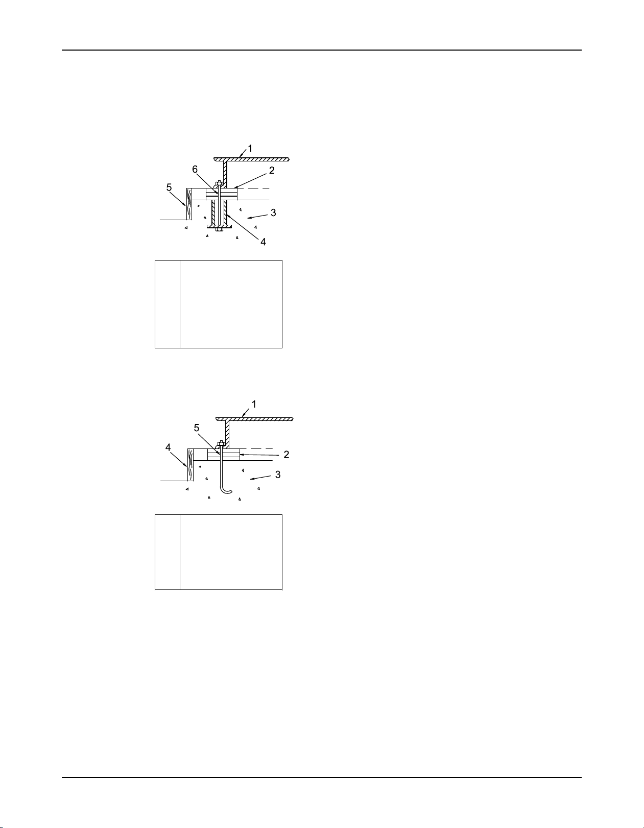
Sleeve-type bolts
Installation
• Sleeve-type and J-type foundation bolts are most commonly used. Both designs allow
movement for the final bolt adjustment.
• The concrete foundation must have sufficient firmness according to DIN 1045 or equal
standard.
Item Description
1. Baseplate
2. Shims
3. Foundation
4. Sleeve
5. Dam
6. Bolt
Figure 4: Sleeve type bolts
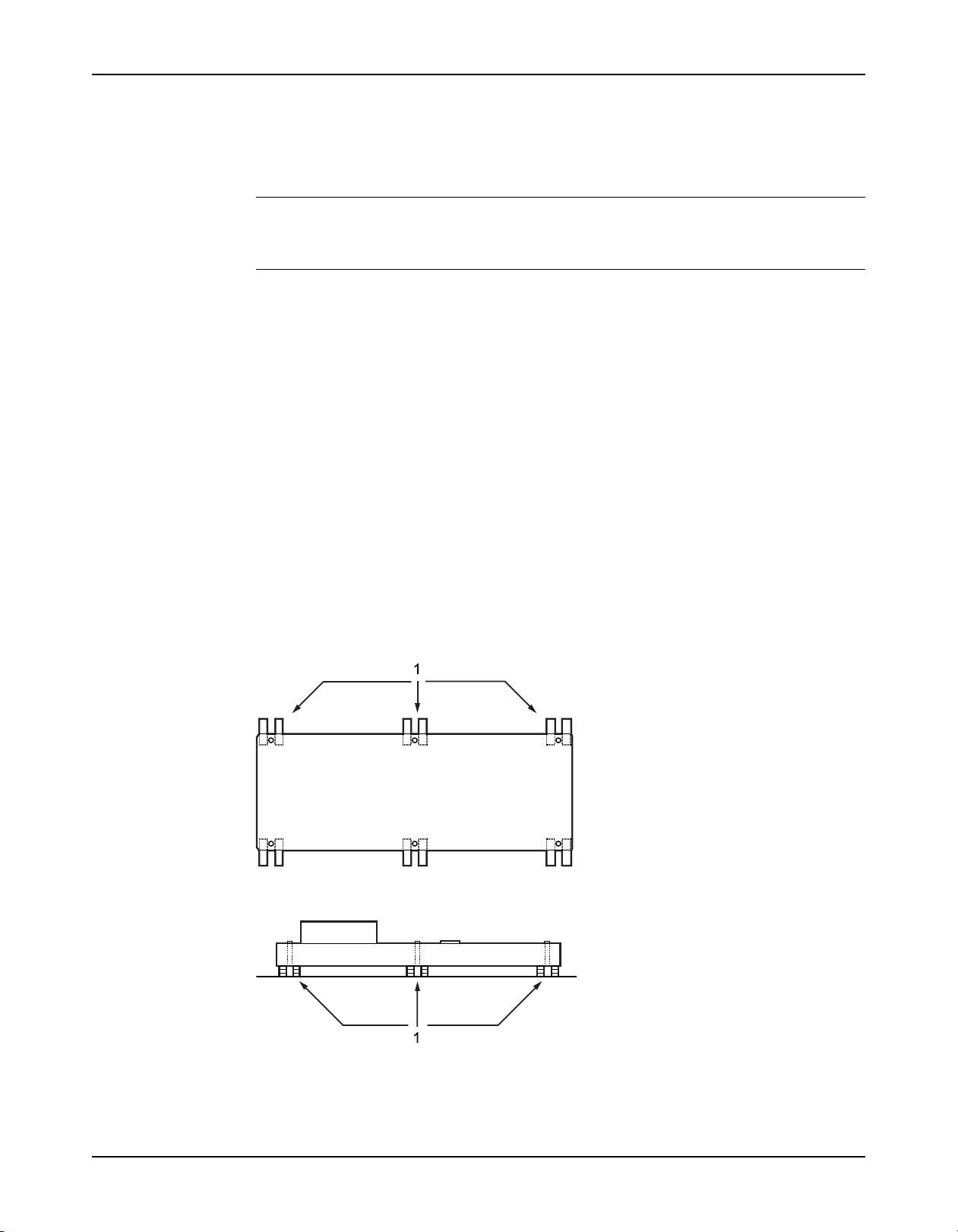
J-type bolts
Item Description
1. Baseplate
2. Shims or wedges
3. Foundation
4. Dam
5. Bolt
Figure 5: J-type bolts
Baseplate-mounting procedures
Prepare the baseplate for mounting
1. Remove all the attached equipment from the baseplate.
2. Clean the underside of the baseplate completely.
3. If applicable, coat the underside of the baseplate with an epoxy primer.
Use an epoxy primer only if you used an epoxy-based grout.
4. Remove the rust-proofing coat from the machined mounting pads using an appropriate
solvent.
5. Remove water and debris from the foundation-bolt holes.
Model 710 TruBlue Installation, Operation, and Maintenance Manual 17
Installation
Prepare the foundation for mounting
1. Chip the top of the foundation to a minimum of 25.0 mm | 1.0 in. in order to remove porous
or low-strength concrete.
If you use a pneumatic hammer, make sure that it does not contaminate the surface with oil
or other moisture.
NOTICE:
Do not chip the foundation using heavy tools such as jackhammers. This can damage the
structural integrity of the foundation.
2. Remove water or debris from the foundation bolt holes or sleeves.
3. If the baseplate uses sleeve-type bolts, then fill the sleeves with a non-binding, moldable
material. Seal the sleeves in order to prevent the grout from entering.
4. Coat the exposed portion of the anchor bolts with a non-bonding compound such as paste
wax in order to prevent the grout from adhering to the anchor bolts.
Do not use oils or liquid wax.
5. If recommended by the grout manufacturer, coat the foundation surface with a compatible
primer.
Install the baseplate using shims or wedges
Required tools:
• Two sets of shims or wedges for each foundation bolt
• Two machinist's levels
• Baseplate-leveling worksheet
This procedure is applicable to cast iron and fabricated steel baseplates.
1. If you use sleeve-type bolts, fill the bolt sleeves with packing material or rags to prevent
grout from entering the bolt holes.
2. Put the sets of wedges or shims on each side of each foundation bolt.
The sets of wedges should have a height of between 19 mm | 0.75 in. and 38 mm | 1.50 in.
1. Shims or wedges
Figure 6: Top view
1. Shims or wedges
Figure 7: Side view
3. Lower the baseplate carefully onto the foundation bolts.
Model 710 TruBlue Installation, Operation, and Maintenance Manual18

Installation
4. Put the machinist's levels across the mounting pads of the driver and the mounting pads of
the pump.
NOTICE:
Remove all dirt from the mounting pads in order to ensure that the correct leveling is
achieved. Failure to do so can result in equipment damage or decreased performance.
5. Level the baseplate both lengthwise and across by adding or removing shims or moving the
wedges.
These are the leveling tolerances:
• A maximum difference of 3.2 mm | 0.125 in. lengthwise
• A maximum difference of 1.5 mm | 0.059 in. across
You can use the baseplate-leveling worksheet when you take the readings.
6. Hand-tighten the nuts for the foundation.
Model 710 TruBlue Installation, Operation, and Maintenance Manual 19

Installation
Baseplate-leveling worksheet
Model 710 TruBlue Installation, Operation, and Maintenance Manual20

Install the pump, driver, and coupling
1. Mount and fasten the pump on the baseplate. Use applicable bolts.
2. Mount the driver on the baseplate . Use applicable bolts and hand tighten.
3. Install the coupling.
See the installation instructions from the coupling manufacturer.
Pump-to-driver alignment
Precautions
WARNING:
• Misalignment can cause decreased performance, equipment damage, and even catastrophic failure of frame-mounted units leading to serious injury. Proper alignment is the
responsibility of the installer and the user of the unit. Check the alignment of all drive
components prior to operating the unit.
• Follow the coupling installation and operation procedures from the coupling manufactur-
er.
• Failure to disconnect and lock out driver power may result in serious physical injury or
death. Always disconnect and lock out power to the driver before performing any
installation or maintenance tasks.
• Electrical connections must be made by certified electricians in compliance with all
international, national, state, and local rules.
• Refer to driver/coupling/gear manufacturer's installation and operation manuals (IOM)
for specific instructions and recommendations.
• Wear insulated gloves to handle the coupling hub. The coupling hub will get hot and can
cause physical injury.
Installation
Alignment checks
When to perform alignment checks
You must perform alignment checks under these circumstances:
• The process temperature changes.
• The piping changes.
• The pump has been serviced.
Types of alignment checks
Type of check When it is used
Initial alignment (cold alignment)
check
Final alignment (hot alignment)
check
Initial alignment (cold alignment) checks
When Why
Before you grout the baseplate This ensures that alignment can be accomplished.
After you grout the baseplate This ensures that no changes have occurred during the grouting
After you connect the piping This ensures that pipe strains have not altered the alignment.
Final alignment (hot alignment) checks
When Why
After the first run This ensures correct alignment when both the pump and the driver
Prior to operation when the pump and the driver are at ambient
temperature.
After operation when the pump and the driver are at operating
temperature.
process.
If changes have occurred, you must alter the piping to remove pipe
strains on the pump flanges.
are at operating temperature.
Model 710 TruBlue Installation, Operation, and Maintenance Manual 21
 Loading...