

ITT PumpSmart PS220 Installation, Operation And Maintenance Manual

PS220 Configuration & Operation Guide
Installation, Operation,
and Maintenance Manual
PumpSmart® Control Solutions PS220 v6

Started
Getting
PS220 Configuration & Operation GuidePS220 Configuration & Operation Guide
Dear Valued Customer,
Congratulations on the purchase of your PumpSmart® PS220 variable
speed frequency drive.
Leveraging our 160+ years in pump design, manufacture, and operation,
ITT has one goal; improving the profitability of your plant. Our products
and services target your biggest issues of process uptime, maintenance,
and energy costs.
The PumpSmart® PS220 integrates an industrial strength variable frequency drive with years of pump control logic and testing. The PumpSmart®
PS220 variable speed pump control system provides real-time control and
protection of your pumps while also providing valuable process insight. By
protecting against unplanned pump failure due to process upsets, ITT can
keep your process running longer and eliminate unplanned repair activities.
By Right-Sizing your pumps to your system, we can reduce not only your
energy consumption, but the wear and tear on your pumps and process
system.
Since 1999 the PumpSmart® patented logic has been changing process control and protection for pumping systems.
From single pump applications to multi-pump applications, the PumpSmart® PS220 can accurately control to pressure,
flow, level, temperature or other process conditions.
For additional information on the PumpSmart PS220 review the configuration manual or visit www.ittmc.com.
Please take the time to review, understand the safe installation, operation and maintenance guidelines provided in the
ACS880 Hardware Manual, PS220 Configuration and Operation Guide and the Installation, Operation and Maintenance
instructions for the applied driven equipment.
The PS220 has been designed for safe and reliable operation when properly installed, applied and maintained in accordance with the instructions in the ACS880 Hardware Manual and PS220 Configuration and Operation Guide. ITT Monitoring and Control shall not be liable for physical injury, damage or delays caused by failure to follow these instructions.
1 PS220

PS220 Configuration & Operation Guide
PS220 Configuration & Operation Guide
Important Safety Reminder Section 1.0 Page 03
PS220 Wizards Section 2.0 Page 05
Basic Startup Section 2.1 Page 07
SmartFlow Section 2.2 Page 23
Process Control Section 2.3 Page 51
Pump and VFD Section 2.4 Page 72
protection
Multipump Section 2.5 Page 104
Multivariable Section 2.6 Page 120
Options and Features Section 3.0 Page 127
Appendices Page 172
Keypad Use A-1 Page 172
Fault Tracing A-2 Page 177
Parameter Listing A-3 Page 189
Basic Wiring & Installation
Multipump connections
Quick Reference
• Wall mount units A-4 Page 206
• Floor mount units
Getting
Started
PS220 2

Started
Getting
PS220 Configuration & Operation Guide
PS220 Configuration & Operation Guide
IMPORTANT SAFETY REMINDER
Products manufactured and furnished by ITT Monitoring and Control will provide safe, trouble-free service when properly
installed, maintained and operated. We have an extensive network of experienced sales and service professionals to assist
in maximizing your satisfaction with our products.
Safe installation, operation and maintenance of ITT’s equipment are essential end user responsibilities. The ACS880 Hardware Manual and PS220 Configuration and Operation Guide identify specific safety risks that must be considered at all
times during the life of the product. Understanding and adhering to these safety warnings is mandatory to ensure personnel, property and/or the environment will not be harmed. Adherence to these warnings alone, however, is not sufficient;
it is expected that the end user will also comply with industry and corporate safety standards. Identifying and eliminating
unsafe installation, operation and maintenance practices is the responsibility of all individuals involved in the installation,
operation and maintenance of industrial equipment.
Safety Symbol and Signal Word Explanation:
This is the dangerous voltage alert symbol. It warns of high voltage which can cause death or physical
injury. Obey all safety messages that follow this symbol to avoid possible injury or death.
This is the safety alert symbol. It is used to alert you to potential personal injury hazards. Obey all safety
messages that follow this symbol to avoid possible injury or death.
DANGER
WARNING
CAUTION
NOTICE
DANGER indicates a hazardous situation which, if not avoided, will result in death or
serious injury.
WARNING indicates a hazardous situation which, if not avoided, could result in death or
serious injury.
CAUTION indicates a hazardous situation which, if not avoided, may result in minor or
moderate injury.
NOTICE used without the safety alert symbol addresses practices which, if not avoided, may
result in property damage.
3 PS220

PS220 Configuration & Operation Guide
PS220 Configuration & Operation Guide
With respect to PumpSmart drives and the operation of pumping equipment the following risks bear reinforcement above
and beyond normal safety precautions:
DANGER
Never work on the PS220 drive, the motor cable or the motor when main power is applied. After switching off
the input power, always wait 5 minutes to allow drive internal capacitors to discharge before working on the
drive, the motor or the motor cable. Failure to do so will result in serious injury or death.
DANGER
Do not work on control cables when power is applied to the drive or to external control circuits. Externally
supplied control circuits may cause dangerous voltages inside the drive even if the main power on the drive is
switched off. Failure to do so will result in serious injury or death.
WARNING
All electrical installation and maintenance work must be undertaken by a qualified electrician only. Failure to do
so could result in serious injury or death.
WARNING
Getting
Started
Operation of any pumping system with a blocked suction and discharge must be avoided in all cases. Operation, even for a brief period under these conditions, can cause superheating of internal pumpage and result in a
violent explosion. All necessary measures must be taken by the end user to ensure this condition does not occur.
Failure to do so could result in serious injury or death.
WARNING
Never operate rotating equipment unless all protective coupling and shaft guards are in place. Personal injury
may occur if the driven equipment is operated without coupling and shaft guards. Failure to do so could result
in serious injury or death.
WARNING
Handle the unit carefully. The PS220 is heavy. Do not lift it alone.
Wall Mounted Units: Do not lift the PS220 by the front cover. Place the unit only on its back.
Floor Mounted Units: Lift the PS220 by the lifting lugs only. Do not tilt the unit. The unit will overturn from a tilt
of about 6 degrees. Use extreme caution when maneuvering a unit that has been placed on wheels.
Failure to do follow these instructions could result in serious injury or death or damage to the equipment
PS220 4

Started
Getting
PS220 Configuration & Operation Guide
PS220 Configuration & Operation Guide
Wizard Menu
The PumpSmart PS220 has incorporated a timesaving Wizard Menu and an extremely versatile range of configurations to
make setup and operation incredibly easy. Instead of navigating through hundreds of parameters the ones needed are all
located in an easy access, intuitive menu structure.
Details on functions not covered in the wizards are listed in the options and features section. Water functions, I/O
Configuration, and parameter lock are covered in the options and features section.
The PS220 wizards have been designed to cover a wide range of common use applications. Unfortunately, they cannot
cover every use case. When reconfiguring the drive for a different setup it is highly recommended to restore the drive’s
parameters to factory settings.
PS220 Configuration Menu
Basic Startup
SmartFlow
Process Control
Pump Protection
Multi-pump
Multivariable
Options & Features
Keypad Use
5 PS220
Fault Tracing
Parameter List
Appendix

PS220 Configuration & Operation Guide
PS220 Configuration & Operation Guide
THIS PAGE IS INTENTIONALLY LEFT BLANK
Startup
Basic
PS220 6

Basic
Startup
PS220 Configuration & Operation GuidePS220 Configuration & Operation Guide
Basic Startup
This section details how to setup your PumpSmart PS220 and configure it to operate in single pump speed control mode.
This is where the Motor Data, Motor ID Run, Direction Check and other basic setup options are performed. After completing this section you can continue setting up your system for SmartFlow, Process Control, Multi-pump, or other PumpSmart
options.
Step Description Parameters
Motor Setup 99.06
1
Drive data for the 99.07
First Motor Run ID is 99.08
entered here 99.09
99.10
Motor Setup
2
Edit Motor ParametersBasic Drive Setup
3
4
5
6
Perform the ID and
Check for proper
motor rotation
Start/Stop
Methods of starting 74.01
and stopping
Speed Range
MAX and MIN drive 30.11
speeds 30.12
Operating Mode
Selects the mode of
operation
Setpoint
Options for setting
a reference
7 PS220

PS220 Configuration & Operation Guide
PS220 Configuration & Operation Guide
Edit Motor Parameters
The PumpSmart PS220 variable frequency drive utilizes Direct Torque Control [DTC] rather than
a scalar speed control variable such as Volts/Hertz. Direct Torque Control provides more precise
speed control, hence more responsive and accurate control to your setpoint. Specific motor data
must be entered into the PumpSmart drive to enable it to properly control the motor using DTC.
Steps to be performed are:
1. Motor Setup
2. Motor Identification Run
3. Motor Jog for Direction
E-Stop/Permissive
The PS220 will not operate unless the
E-Stop/Permissive switch [DIIL] is closed.
This includes performing the Motor ID
Run. If not closed a warning message
will appear on the keypad display:
See Appendix A-4, Instrument Wiring,
for details on wiring this switch.
NOTE – The E-Stop/Permissive switch cannot
be defeated through parameter setting. If your
application does not use an E-Stop / Permissive
switch, DIIL can be bypassed physically inside the
PumpSmart unit. Refer to Appendix A-4,Instrument Wiring, for details.
Startup
Basic
PS220 8

Basic
Startup
PS220 Configuration & Operation GuidePS220 Configuration & Operation Guide
Motor Setup
From the PS220 Configuration Menu select Basic
Startup; if this is the first time the drive has been
started then it will automatically open to the Basic
Startup wizard. Inside of Motor Setup the motor
data must be entered. The motor data will allow
the PumpSmart drive to characterize the motor
prior to its first startup. During characterization,
PumpSmart will automatically magnetize the
motor windings for 20 – 60 seconds to develop
a mathematical model of the motor. Entry of the
following parameters is all that is required.
Note – If the motor is replaced in the future, this
data must be re-entered and a new
characterization will be performed.
The information required for this section can be
found on the motor nameplate.
Enter the Motor Nominal Current (full load amps)
as found on the motor nameplate, along with the nominal voltage, and nominal frequency.
Enter the full load speed of the motor as found on the nameplate, not the nominal speed.
Enter the nominal power (hp or kW) of the motor; if you are using the default language of
English U.S., then the units of entry will be horsepower.
Example 1.1 – An 1800 RPM motor might have a full load speed of 1770 rpm.
Select Edit Adjust
9 PS220

PS220 Configuration & Operation Guide
PS220 Configuration & Operation Guide
Motor ID
Motor Identification Run: PumpSmart uses specific
motor details to create a mathematical model.
This model enables more accurate motor control
and is created using the motor data you have just
entered by magnetizing the motor for 20 to 60
seconds at zero speed. This is called a Standstill ID
run.
Once all the motor data has been entered, you
will see the following warning flash on top of the
screen:
This warning indicates that a Motor Identification
run is required before the pump may be operated.
Now is a good time to perform this run.
Note – Although the motor may not appear to
respond to the start command, it has. Alternatively,
you may hear an audible high pitched sound coming from the driven equipment.
The following procedure will energize the motor. All safety precautions must be followed before initiating the Motor ID run. Failure to do so could result in serious injury or death.
A warning message, “ID run Active” will be displayed during the ID. Once the ID run is complete, the message “ID DONE” will be displayed.
Note – If the motor is replaced in the future, a Motor Identification run must be performed
again to maintain the accuracy of the PumpSmart drive, with the new driven equipment.
Once this appears, proceed on to the next step, Motor Jog.
WARNING
The following procedure
will energize the motor. All
safety precautions must be
followed before initiating
the Motor ID run. Failure to
do so could result in serious
injury or death.
Startup
Basic
Select Start Wait
PS220 10

Basic
Startup
PS220 Configuration & Operation GuidePS220 Configuration & Operation Guide
Jogging the Motor
Checking the motor for rotation can be accomplished through the Motor Jog function in which
the pump will rotate 60rpm until the operator affirms the direction of the motor, a stop command
is received, Fault, or Emergency Stop occurs.
Note – If pump rotation is incorrect then there
is NO NEED to change the output phases of the
drive. The drive can automatically do an internal
swap of the output power phases. Swapping two
of the input phases will not change the rotation of
the drive.
DANGER
Never work on the PS220 drive, the motor
cable or the motor when main power
is applied. After switching off the input
power, always wait 5 minutes to allow
drive internal capacitors to discharge
before working on the drive, the motor
or the motor cable. Failure to do so will
result in serious injury or death.
Note – The jog function does not account for a Start delay, parameter
74.04 START DELAY must be 0 to perform the jog. The jog will only
follow the reference speed of 60rpm if the drive is set to have the Keypad
as the reference source, otherwise it will follow the minimum speed set in
parameter 30.11.
Start
SelectWait
11 PS220

PS220 Configuration & Operation Guide
PS220 Configuration & Operation Guide
Basic Drive Setup
Basic Drive Setup outlines how to get the PS220 drive running in Speed Control,
with the option to setup Process Control when selecting the Operation Mode. Upon
completion of Basic Drive Setup, and as a result the completion of Basic Startup, the
user is strongly encouraged to go through other Wizards in the PS220 Configuration
Menu. Protecting your system, setting up Multipump systems and more all start
after completing this section.
Steps to be performed are:
1. Starting and Stopping Options
2. Selecting the Speed limits of the motor
3. Speed Control operation mode
a. Entering the Setpoint
b. Recommended Steps
c. Starting and Stopping the drive
4. Process Control operation mode
a. Continue to Process Control tabbed section
Startup
Basic
Level vs. Edge
The PS220 has multiple external Start/
Stop options that either requires constant high input to the drive (level) or
a transition from either low to high or
high to low inputs (edge). for example,
HOA and 2 Wire are level type inputs,
where 3 wire is an edge type input.
See Appendix A-4, instrument Wiring,
for details on wiring Start/Stop Switches.
WARNING
The drive will start if it is receiving a high start
input and it is in a Level Start/Stop mode after all
faults are cleared and interlocks are closed.
PS220 12
Basic
Startup
PS220 Configuration & Operation GuidePS220 Configuration & Operation Guide
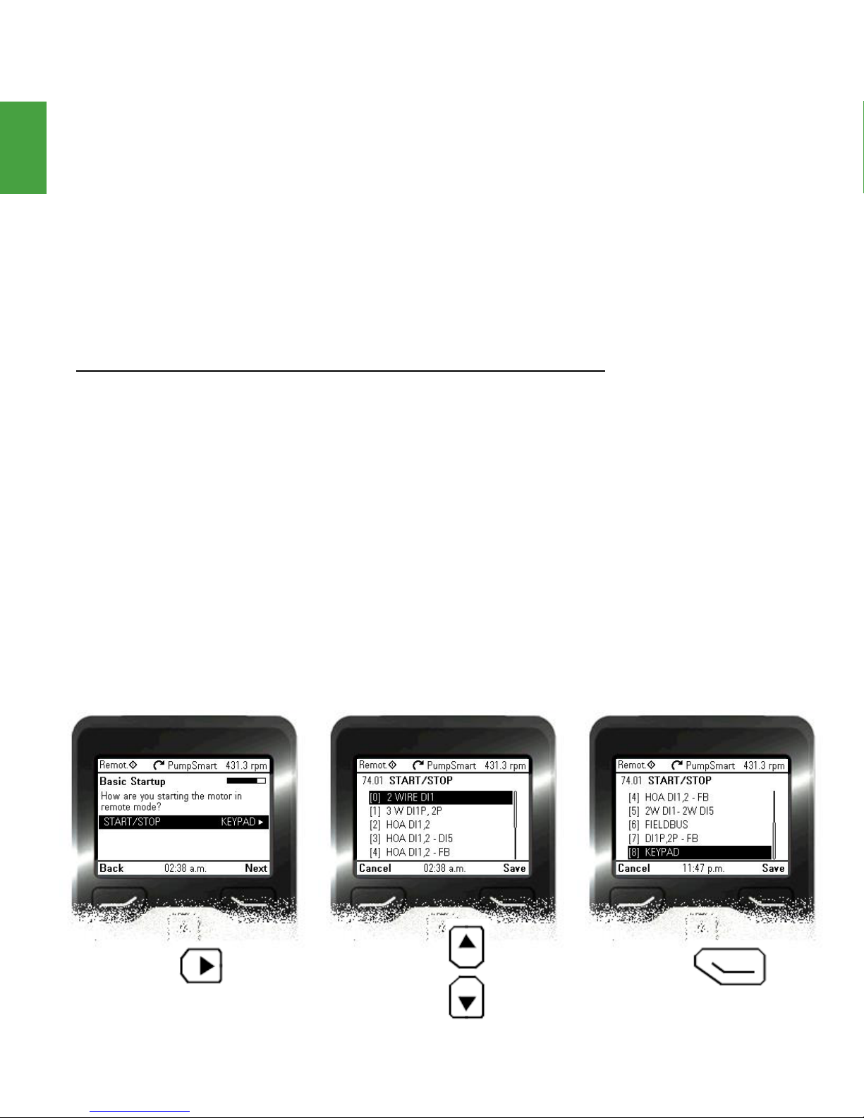
Start/Stop
The PumpSmart PS220 has the ability to be remotely started and stopped from an external source. Also, the PS220 can have the keypad included as a remote Starting and Stopping location! If the PS220 will be operated without any external switches for starting
and stopping, then please proceed to the next step, keeping the default option “Keypad”.
Note – The PS220 has the ability to be controlled from two separate external commands.
Refer to Options and Features – Start/Stop Options.
Note – The following options only apply when the PS220 is in REMOTE mode, as indi-
cated in the top left corner of the keypad screen. When in LOCAL mode the Start/Stop
is controlled through the PS220 keypad exclusively. Refer to APPENDIX A-1 KEYPAD USE
for further details.
2 WIRE DI1 – This selection is used to start and stop the PS220 from a maintained
2-wire switch or contact wired to DI1 – Start/Stop.
3 W DI1P, 2P – This selection is used to start the PS220 from a normally open momentary contact/switch wired to DI1 – Start, and stop the PS220 from a normally closed
momentary contact/switch wired to DI2 – Stop.
HOA DI1, 2 – This selection is used to start and stop the PS220 from a maintained
2-wire switch or contact wired to DI1 – AUTO. An additional contact can be wired to DI2
– Hand to initiate a Speed Override/Motor Jog function, in which the PS220 will operate
in a speed control mode. See Options and Features-Speed Override.
FIELDBUS – This selection is used to start and stop the PS220 from a Control Word sent
via a digital Fieldbus command. See Options and Features-Fieldbus Communication.
SaveEdit Scroll
13 PS220

PS220 Configuration & Operation GuidePS220 Configuration & Operation Guide
Speed Range
The Speed Range defines the drive’s safe operating
limits. These limits safeguard the pump and drive
system from operating in unstable overspeed and/
or low-speed conditions.
Maximum Speed: The PumpSmart System will
adjust the speed of the motor to achieve the desired operating setpoint. Although the PumpSmart
System can drive the motor at 2-3 times its
nameplate speed, this is generally impractical for
several reasons. First, unless the pump and motor
are designed for overspeed operation, they could
prematurely wear or even catastrophically fail.
Second, centrifugal pumps generate pressure by
the square of the speed and overspeed operation
may overpressure the pump or surrounding piping
system.
Enter the maximum speed that the pump, motor,
and system can operate at. In most cases the maximum speed will be the same as the previously entered full load RPM.
WARNING
Startup
Basic
The default value is the speed set in parameter 99.09 Motor nominal speed.
MAX SPEED ≤ Full Load Motor RPM & Pump Max Speed
Assure that the system operating conditions
are within the capabilities (e.g. speed, pressure,
temperature, power, etc.) of the driven equipment as rated by the manufacturer. Exceeding
any of these limits could result in failure of
components resulting in serious physical injury
and damage to equipment
SaveEdit Next
PS220 14

Basic
Startup
PS220 Configuration & Operation GuidePS220 Configuration & Operation Guide
Speed Range cont’d
Minimum Speed: As the demand on the pump decreases, PumpSmart will decrease the
pump speed to match the new demand. This Minimum Speed parameter sets the minimum speed that the pump can operate at. It is also used to define the safe speed to run
the pump during a pump protection fault. The default value for minimum speed is 25%
of 99.09 Motor nominal speed.
When determining a minimum speed, consider the following:
1. Motor Minimum Speed [Turndown ratio]: Due to motor loading and thermal effects,
the motor minimum speed on centrifugal pumps should not be less than 1/10th its
full-load speed.
2. Pump Minimum Speed: Some pumps have minimum speed requirements, such as
multistage pumps (>2 stages) and sleeve bearing pumps. Consult your pump
operation manual to see if there is a minimum speed limit for your pump. Note: 1 &
2 stage pumps do not normally have minimum speed requirements.
3. Static Head Conditions (minimum flow): The minimum speed should be set to assure
that the pump generates enough head to overcome static resistance. In some cases,
this can cause overheating and possible vaporization of the liquid in the pump casing.
Notice
Operation below the pump safe minimum
speed could result in damage to equipment
and/or property.
Enter the minimum speed that the pump and motor can safely operate at.
The default value is 25% of the speed set in parameter 99.09 Motor nominal speed.
Minimum Speed Sleep: The default settings will stop the pump if the process demand
requires the pump to operate below minimum speed. In the process control modes of
Pressure and Level control a SLEEP WARNING will be displayed in this case. The Sleep
Function will suspend the PS220 until process demand increases as defined by the RESTART VALUE (parameter 75.06). Once the Restart Value has been achieved for longer
than the restart delay the pump will automatically restart to maintain the process setpoint.
Low Demand: In the flow control mode, control parameter 75.03 Sleep mode needs to
be changed to OFF. A PID LOW DEMAND fault will occur in which case the PS220 will
have to be manually reset. Alternatively, the drive may be set to operate at a minimum
speed until it is manually shutoff (parameter 79.16 Config Min Speed).
For a step by step procedure and more details please go to the Process Control tabbed
section and see Sleep Mode.
15 PS220

PS220 Configuration & Operation GuidePS220 Configuration & Operation Guide
Operating Mode
In this section, the operating mode of the PS220
is selected. Configuring the drive in either Speed
Control or Process Control is necessary to operate
the drive.
Speed Control Configuration: In this setup, the
drive is configured to operate the driven equipment at a desired speed setpoint. A speed
setpoint can be input via the keypad, an external
analog signal, or Fieldbus. As an example an external PID Controller (DCS/PLC/etc.) can be used to
feed the PS220 with a reference speed signal.
Process Control Configuration: The PS220 is a
drive and Pump PID Controller all-in-one. The
Process Control Wizard needs to be completed
to operate the PS220 in a single pump (or Multipump) process control mode. In this mode, a
single pump is connected to your system with a
transmitter (pressure, level, flow, temperature, etc.)
wired to the PS220 to provide process
condition feedback. Alternatively, the drive features sensorless flow control with SmartFlow.
Startup
Basic
If the selection is Speed Control then the next page will ask the user to choose a setpoint
source. If the selection is instead Process Control, then a Pop-up window will ask the user to
please run the Process Control Wizard to configure the PS220.
Important!
PLEASE CONTINUE TO THE PROCESS CONTROL
SECTION IF YOU ARE OPERATING YOUR PUMP
IN PRESSURE, FLOW, LEVEL, SMARTFLOW, OR
TEMPERATURE CONTROL MODES.
OTHERWISE CONTINUE TO THE NEXT PAGE.
PS220 16

Basic
Startup
PS220 Configuration & Operation GuidePS220 Configuration & Operation Guide
Setpoint (Speed Control)
In Speed Control, the desired running speed may
be selected in one of three ways:
1. Keypad [Default]
2. Speed Reference (via Analog input)
3. Fieldbus Control
The following details the use of a speed signal to
set the operating speed of the pump. This section
covers setting a speed reference locally at
the keypad or sending a speed reference via a
4-20mA signal wired to an Analog Input. For an
analog signal that is 2-10VDC, please see Options
and Features-Configuring the Analog Input Configuration.
Note – If you are using a Fieldbus reference please
refer to the Options and Features-Fieldbus.
Keypad: If you are using the Keypad for entry of
the running speed you can edit it on the Home Screen whenever you see the symbol next to
the reference. On the Home Screen the up and down arrow keys of the keypad will directly adjust your speed reference. Alternatively, under “Options” the reference can be adjusted quicker,
as seen below.
Note – To navigate back to the Home screen from anywhere in the drive Menus press the left
softkey as long as it is the Back/Exit option.
Note – There are several
alternate ways to enter a
speed setpoint. Refer to
the Options and Features-Setpoints.
No EditOptions
17 PS220

PS220 Configuration & Operation GuidePS220 Configuration & Operation Guide
Setpoint (Speed Control) cont’d
Speed Reference: For an analog speed signal, to
set the operating speed of the pump signal MAX
and MIN settings are required to properly scale the
signal. Either Analog Input 1 (AI1) or Analog Input
2 (AI2) can be chosen to receive an analog input
speed signal.
“AI1 scaled at AI1 min” is parameter 12.19 and
refers to the speed value that corresponds to the
minimum of the signal (4mA).
Example 1.2 – If you want your process to run at
800rpm when the 4-20mA speed signal is 4mA,
then you would enter “800” into parameter 12.19.
“AI1 scaled at AI1 max” is parameter 12.20 and
refers to the speed value that corresponds to the
maximum of the signal (20mA).
Example 1.3 – If you want your process to run at
3600rpm when the 4-20mA speed signal is 20 mA, then you would enter “3600” into parameter 12.20.
When using a 4-20mA speed reference the Analog Input that the signal is wired to must be
defined in the drive. The Basic Startup wizard automatically defines the selected analog input
to “EXT SETPOINT 1” for the speed reference for the user.
Startup
Basic
Edit YesSave
PS220 18

Basic
Startup
PS220 Configuration & Operation GuidePS220 Configuration & Operation Guide
Recommended Step: Parameter Upload
Save your parameters in the Keypad. In the unlikely event that the PS220 parameters are lost, the
Keypad can be used to restore the configuration.
It can also be used to program sister drive units
that use the same or similar program settings. For
more information refer to Options and FeaturesParameter Backups.
19 PS220
Select WaitScroll
PS220 Configuration & Operation GuidePS220 Configuration & Operation Guide
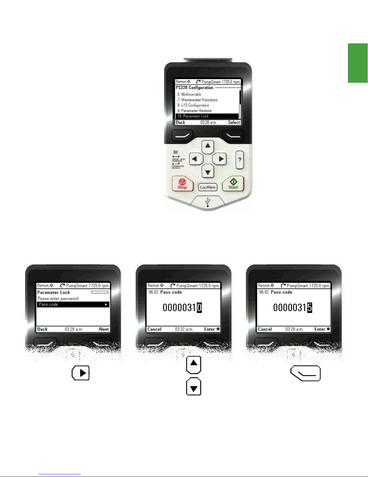
Recommended Step: Locks & Passcodes
Operating parameters on the PS220 are protected
by a 3-digit passcode to prevent casual users or
unauthorized users from inadvertently changing
operating and protection limits that have been set.
All PS220 units utilize the same passcode; it cannot
be changed by the user/owner.
Navigating to the Parameter Lock Wizard will
allow you to enter the PS220 passcode. When the
PS220 Keypad is locked, functionality is limited to
starting, stopping, and changing the operating
setpoint.
00000358 = Parameter Lock
00000315 = Basic user access
00000568 = Advanced user
Startup
Basic
EnterEdit Adjust
PS220 20

Basic
Startup
PS220 Configuration & Operation GuidePS220 Configuration & Operation Guide
Starting & Stopping
Congradulations, the PumpSmart system is now
ready to start in Speed Control. Starting and
stopping the PumpSmart unit is always possible
through the Keypad when in LOCAL mode and
through a remote signal as defined in parameter
74.01 “Start/Stop” when in REMOTE mode. Please
note the keypad can be considered a remote location if set accordingly in 74.01.
LOCAL and REMOTE control modes can be
changed via the “Loc/Rem” button located on the
keypad. To verify if the drive is in LOCAL, check
the top left hand corner for the current mode,
either “Local” or “Remote”. A diamond symbol
will appear next to the word Local/Remote if the
start command can be given via the “Start” button
on the Keypad. PS220 Features are designed to
operate in REMOTE mode.
WARNING
Never operate rotating equipment unless all protective coupling and shaft guards
are in place. Personal injury may occur if the driven equipment is operated without
coupling and shaft guards.
WARNING
Observe all CAUTIONS and WARNINGS highlighted in the ACS880 Hardware
Manual, PS220 Configuration and Operation Guide and Installation, Operation and
Maintenance Guide for the applied driven equipment prior to starting.
Below outlines the process to switch between Local and Remote modes.
21 PS220
StartLoc/Rem Set reference

PS220 Configuration & Operation Guide
PS220 Configuration & Operation Guide
THIS PAGE IS INTENTIONALLY LEFT BLANK
SmartFlow
PS220 22

PS220 Configuration & Operation GuidePS220 Configuration & Operation Guide
SmartFlow
SmartFlow
PumpSmart can calculate the flow of a centrifugal pump based on torque, power,
and speed feedback derived from the drive. By comparing these values against
the pump’s performance curve PumpSmart can calculate the flow of the pump
within ±5% of the pump’s maximum rated flow. This section details how to setup
the PumpSmart PS220 drive to calculate SmartFlow using only four pieces of data
from the published pump performance curve. Please note Basic Startup must be
completed before you can complete this section. After completing this section
you can continue setting up your system for Process Control, Multi-pump, or other
PumpSmart options.
Step Description Parameters
1
2
Basic SmartFlowAdvanced SmartFlow
3
4
5
6
Flow Unit
selection
Pump
Parameters
Specific Gravity
Data
Calculation
Method
Pump System
Properties
Configure
Analogs
77.01 to
77.06
78.02
78.03
77.02
77.07 to
77.15
23 PS220

PS220 Configuration & Operation Guide
PS220 Configuration & Operation Guide
Basic SmartFlow
The PumpSmart PS220 variable frequency drive utilizes a sophisticated and proven algorithm
to calculate pump output flow. Basic SmartFlow is designed for low to medium specific speed
pumps and is appropriate for the majority of pump applications. Basic SmartFlow is ideal for
Pumps with a constantly rising power curve, i.e. non drooping, does not have multiple peaks
or valleys. For high specific speed pumps that do not have a constantly rising power curve it is
advised to use Advanced SmartFlow.
Although factory pump performance curve data can be used it is not required. A tune function
calibrates the Flow vs Power curve to compensate for mechanical losses, volumetric efficiency,
casting defects, pump wear, eddy current losses, and general pump performance defects that can
have an effect on the total pump efficiency.
Steps to be performed are:
1. Select Flow Unit
2. Pump Properties
3. Specific Gravity Correction
SmartFlow
PS220 24

PS220 Configuration & Operation GuidePS220 Configuration & Operation Guide
Flow Unit
From the PS220 Configuration Menu select
SmartFlow; if this is the first time the drive has
SmartFlow
been started then it will automatically open to
the Basic Startup wizard. Basic Startup must be
performed before running the driven equipment;
if you have already completed Basic Startup
please proceed.
The SmartFlow unit selection identifies what units
your SmartFlow reading is in. This parameter
sets the units that are used in the SmartFlow and
System Flow parameters. Below outlines the
procedure for selecting a flow unit.
Note – Whether the primary process units are
Imperial or Metric the SmartFlow unit is set
independently to the unit of your choice.
25 PS220
SelectScrollSelect

PS220 Configuration & Operation Guide
PS220 Configuration & Operation Guide
Pump Properties
The first step in setting up SmartFlow is to define
the pump characteristics in the drive. The required
pump data should be set up for the rated speed
and impeller diameter of the pump. Entry of the
following parameters is required.
The information required for this section can be
found on the Pump Performance Curve.
To setup SmartFlow the pump type must be defined as one of the following choices:
• SS Centrifugal – Single Suction Centrifugal
• DS Centrifugal – Double Suction Centrifugal
• Mag Drive – Magnetic Drive Pump
Note – For magnetic drive pumps with metallic
containment shell select Mag Drive, for nonmetallic shells select SS Centrifugal as the Pump
Type.
SmartFlow
Four pieces of information are required from the Pump
Performance Curve supplied by the pump manufacturer;
BEP FLOW, BEP POWER, SHUTOFF POWER, and RATED
SPEED. The chart on the next page is an example of a
typical Pump Performance Curve [Figure 2.1].
Note – If the pump is replaced in the future, this data
must be re-entered and a new tune will need to be
performed unless using the Affinity laws.
Save Edit Adjust
PS220 26

PS220 Configuration & Operation GuidePS220 Configuration & Operation Guide
Pump Properties Cont’d
SmartFlow
Figure 2.1: Pump Performance Curve
This is an example of a typical Pump Performance Curve.
Note – The RATED SPEED must be less than or equal to the setting in parameter
30.12 Maximum Speed. Correspondingly the BEP FLOW, BEP POWER and SO POWER
must be calculated for this rated speed at the rated viscosity.
27 PS220

PS220 Configuration & Operation Guide
PS220 Configuration & Operation Guide
Specific Gravity
The default value for Specific Gravity [SG] is 1.0.
For a system that has a constant SG, a selection
of SG Rated is all that is necessary. For a SG
other than 1.0 adjust SG RATED as necessary; see
Constant Specific Gravity below. In systems with
variable Specific Gravities a Specific Gravity correction is necessary and can be accomplished in
multiple ways.
A pump may be subjected to varying Specific
Gravity of the process fluid. This can occur when
the pump is designed to handle different types of
fluids. Additionally Specific Gravity can be affected by changes in temperature of the process
fluid. When using SmartFlow and Advanced Pump
Protection significant changes in SG can have an
impact on the performance and accuracy of these
functions.
SmartFlow
Constant Specific Gravity
Save Edit Adjust
PS220 28

PS220 Configuration & Operation GuidePS220 Configuration & Operation Guide
Varying Specific Gravity based on Temperature:
If the changes in SG are directly related to changes in temperature then PumpSmart can monitor a temperature
transmitter and automatically correct the SG based on the temperature of the fluid. To calculate the SG based on
SmartFlow
temperature six points of data are required; TEMP MIN at SG MIN, TEMP MID at SG MID, TEMP MAX at SG MAX.
The rated values TEMP RATED at SG RATED can be set to repeat the TEMP MID at SG MID.
Save Edit Edit
Varying Specific Gravity based on SG Transmitter:
The PS220 allows the option to connect a SG transmitter to indicate changing SGs of process fluids being pumped
using a 4-20mA input. The SG is linearly scaled from the AI MIN (4mA) to the AI MAX (20mA) values as entered
below. Be sure to select an available Analog Input.
Save EditSelect
29 PS220
 Loading...