

Page 1

Page 2

ProSmart Installation & Operation Guide
This page was intentionally left blank.
Page 3

ProSmart Installation & Operation Guide
Index
Important Safety Reminder
Getting Started Section 1
Communication Module Installation Section 2
Communication Configuration
Mechanical Installation
Power Connections
Data Monitor Installation Section 3
Mechanical Installation
Power Connections
Class I Division 2 Cap Lock Installation
Sensor Installation Section 4
Tachometer Sensor Installation
Vibration & Temperature Sensor Installation
ProNet User Guide Section 5
Logging into ProNet
Dashboards
My Machines
Data and Trending
Analytical Features
Appendices
MODBUS Information A-1
ProSmart Data Sheets A-2
Troubleshooting A-3
Page 4

ProSmart Installation & Operation Guide
This page was intentionally left blank.
Page 5

ProSmart Installation & Operation Guide
SAFETY INSTRUCTIONS
IMPORTANT SAFETY REMINDER
To: Our Valued Customers
The information in this section must be studied before attempting any work on
or with the ProSmart Wireless Condition Monitoring System.
Products manufactured and furnished by ITT Monitoring and Control will
provide safe, trouble-free service when properly installed, maintained and
operated. We have an extensive network of experienced sales and service
professionals to assist in maximizing your satisfaction with our products.
Safe installation, operation and maintenance of ITT’s equipment are essential
end user responsibilities. The ProSmart Installation and Operation Guide
identify specific safety risks that must be considered at all times during the life
of the product. Understanding and adhering to these safety warnings is
mandatory to ensure personnel, property and/or the environment will not be
harmed. Adherence to these warnings alone, however, is not sufficient; it is
expected that the end user will also comply with industry and corporate safety
standards. Identifying and eliminating unsafe installation, operation and
maintenance practices is the responsibility of all individuals involved in the
installation, operation and maintenance of industrial equipment.
Safety Symbol and Signal Word Explanation:
This is the dangerous voltage alert symbol. It warns of high voltage which
can cause death or physical injury. Obey all safety messages that follow this
symbol to avoid possible injury or death
This is the safety alert symbol. It is used to alert you to potential personal
injury hazards. Obey all safety messages that follow this symbol to avoid
possible injury or death.
DANGER indicates a hazardous situation which, if not avoided,
will result in death or serious injury.
WARNING indicates a hazardous situation which, if not avoided,
could result in death or serious injury.
CAUTION indicates a hazardous situation which, if not avoided,
may result in minor or moderate injury.
NOTICE
NOTICE used without the safety alert symbol addresses
practices which, if not avoided, may result in property damage.
Page 6

ProSmart Installation & Operation Guide
SAFETY INSTRUCTIONS
With respect to ProSmart Wireless Condition Monitoring System installation,
operation, and maintenance activities the following risks bear reinforcement
above and beyond normal safety precautions:
All electrical installation and maintenance work must be undertaken by a
qualified electrician only. Failure to do so will result in serious injury or death.
During installation all equipment must be disconnected from the power supply
without any possibility of being made live (Lockout/Tagout). Failure to do so
will result in serious injury or death.
The ProSmart System is designed and certified only to be installed in a nonhazardous location or a hazardous location labeled as Class I Division 2, Group
A B C D T4 only. The rating is contingent to proper installation of modules for
Class I Division 2. Failure to do so could result in serious injury or death.
The Data Monitor requires 12-24VDC and the Communication Module requires
12VDC. Connecting the module to AC or a higher voltage could result in
serious injury or property damage.
The Communication Module and Data Monitor are equipped with a radio
transmitter and receiver operating in the 2.4GHz band. To satisfy FCC radio
frequency exposure requirements for mobile type transmitting devices, a
separation distance of 20cm or more should be maintained between the
antenna of the Communication Module and Data Monitor and persons during
operation, with exception of hands, wrist, feet, and ankles. To ensure
compliance, operations at distance closer than 20cm are prohibited. Excessive
radio frequency exposure should be avoided.
The Data Monitor is equipped with a relay output. This relay output may be
activated as soon as power is connected to the unit. This may result in
unintended consequences. To ensure the relay activates only when desired, do
not connect the Data Monitor relay wires until the system accepting the
contact closure is ready (alarm beacon, horn, etc.).
The DC capacitors contain electrolyte and the printed circuit boards contain
lead, both of which will be classified as hazardous waste within the EU. They
must be removed and handled according to local regulations.
Page 7

ProSmart Installation & Operation Guide
SAFETY INSTRUCTIONS
Due to some materials used in some electrical components, thoroughly wash
hands with soap and water after handling any electrical components. Always
use protective glasses, gloves, and clothing.
NOTICE
No modifications should be made to the Communication Module and Data
Monitor enclosures and the cover should not be removed from the Data
Monitor Electronic Board Chamber; otherwise, the warranty will be void.
Please take the time to review and understand the safety instructions,
installation and operation guidelines provided in the ProSmart Installation and
Operation Guide for the applied equipment.
The ProSmart System has been designed for safe and reliable operation when
properly installed, applied and maintained in accordance with the instructions
in the ProSmart Installation and Operation Guide. ITT Monitoring and Control
shall not be liable for physical injury, damage or delays caused by failure to
follow these instructions.
Page 8

ProSmart Installation & Operation Guide
SAFETY INSTRUCTIONS
This page was intentionally left blank.
Page 9

ProSmart Installation & Operation Guide
GETTING STARTED
INTRODUCTION
The ProSmart Wireless Condition Monitoring System provides a cost effective method to monitor all types
of rotating equipment all year around - 24 hours a day; 7 days a week; 365 days a year. The ProSmart
System collects machine specific information and provides warnings and alarms to users. The ProSmart
System is designed around ease of installation, rapid deployment, easy system expansion, and no
additional IT infrastructure required. A user needs very little training to start using the ProSmart system.
The ProSmart System consists of four core components: ProNet Server Application, Communication
Module, Data Monitor, and Sensors.
ProNet Application
An internet based system providing Graphical User Interface for Analysis Tools such as FFTs and Band
Alarms, Event and Alarm Management, and Historical Data Management. ProNet automatically alerts the
select users to alarms via e-mail or voice phone calls so that the problem can be rectified before it results
in machine failure. Data storage and maintenance is handled by ITT and requires minimal IT involvement.
Communication Module
A field mountable wireless data communication module, manages all data communication between the
Data Monitor module(s) and ProNet server application. The Communication Module supports
communication to the server via Local Area Networks (LAN), dedicated broadband connection such as
cable and DSL, GPRS, and CDMA cell modems.
Data Monitor
A field mountable wireless data monitoring module for capturing, analyzing, and processing conditions of
any rotating equipment such as pumps, compressors, blowers, fans, mixers, etc. using Sensors and
analog/digital inputs. The Data Monitor should be mounted in close proximity to the machine.
Sensors
Range of ProSmart specific industrial “Plug and Play” sensors measuring Vibration, Temperature, and
Speed. ProSmart also allows 3 analog process inputs in the form of 4-20mA to be analyzed. ProSmart will
also analyze 2 digital inputs in the form of 0-24VDC. This moves ProSmart from being just a vibration
monitoring device to a complete condition monitoring solution.
ProSmart and its related products are protected by the following patents: 6,464,464; 6,487,903
B2; 6,564,627; 6,591,697; 6,648,606; 6,681,634 B2; 6,776,584; 7,080,508 B2; 7,112,037 B2.
Page 9
Page 10

ProSmart Installation & Operation Guide
GETTING STARTED
ProSmart Wireless Condition Monitoring System Architecture
Page 11
ProSmart Installation & Operation Guide
GETTING STARTED
GETTING STARTED
How to use this guide
This guide has been organized to make installation of the
ProSmart System easy. Installation has been divided into three
main sections that include all the information needed to get upand-running. The four sections are:
x Communication Module Installation
x Data Monitor Installation
x Sensor Installation
x ProNet User Guide
Each section has been laid out to speed you through the
installation process, while providing enough background
information to help understand the process.
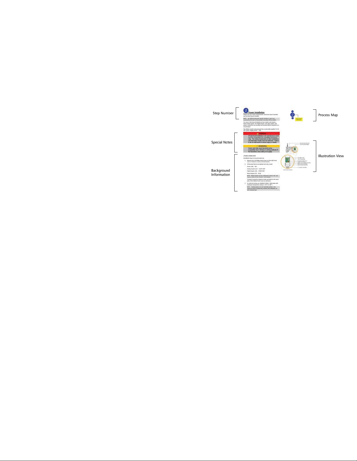
1. Step Number - The step number helps to keep track of
where you are in the configuration process when used in
conjunction with the process map.
2. Process Map - The process map is a visual guide of what
needs to be done in the step.
3. Background Information - This information explains what
the upcoming steps are and why they are being performed.
Examples are provided to assist in understanding the
concept.
4. Special Notes - These highlighted sections contain
comments that are important to the installation process.
5. Illustration View - The illustration view shows installation
illustration for guidance.
PROSMART
Figure A - Typical Installation Page
Page 12

ProSmart Installation & Operation Guide
GETTING STARTED
This page was intentionally left blank.
Page 13

ProSmart Installation & Operation Guide
COMMUNICATION MODULE INSTALLATION
COMMUNICATION MODULE INSTALLATION
This section is devoted to install your ProSmart Communication Module.
Step Description
Communication Module Overview
Communication Module
1
2
3
Communication Overview
Mechanical Installation
Power Connections
PROSMART
Page 13
Page 14

ProSmart Installation & Operation Guide
COMMUNICATION MODULE INSTALLATION
Overview - Communication
When selecting an installation site for the Communication Module
two communication paths need to be evaluated:
1. Communication signal strength between Communication
Module and Data Monitor - It is recommended to optimize the
communication signal from the Communication Module to each
Data Monitor by having ITT or an authorized distributor
perform a site survey.
2. Reliable Internet connection for Communication Module to
communicate with the ProNet server - the Communication
Module can communicate using either Local Area Network,
Broadband connection such as DSL, cable modem, or cellular
modem, similar to an internet connection with a personal
computer.
The Communication Module communicates to the ProNet Server
application through a standard internet connection. The
Communication Module is equipped with an Ethernet cable to
connect into your network receptacle. The Ethernet cable for the
Communication Module exits through the same conduit hub as the
DC power.
All communication is initiated from the Communication Module.
Inbound communication requests to Communication Module are
ignored since it acts only as a client and not as a server. Factory
default configuration for the Communication Module is DHCP
(Dynamic Host Configuration Protocol). It may also be configured to
use a static IP.
The Communication Module allows only specific DMs to send data.
The Communication Module will set aside time in its polling routine
for a listed DM to communicate.
CDMA
GPRS
www
LAN
Communication Module
PROSMART
DSL
Page 15

ProSmart Installation & Operation Guide
COMMUNICATION MODULE INSTALLATION
1
Communication Configuration
NETWORK SPECIFICATIONS
If communicating through a Local Area Network (LAN), it must be
configured to allow communication from the Communication
Module to the following URL address and through the following
ports, especially if the Communication Module must be behind a
firewall:
x data.prosmart.ittmc.com
downloads.
NOTE – Configure LAN network for URL address and not the
resolved IP address since IP address can change anytime.
x Outbound communication support for:
o HTTP Protocol (standard web browser protocol) via
port 80
o External NTP (standard Network Time Protocol) via
port 123
ProNet users must have access to www.prosmart.ittmc.com
login to the GUI (Graphical User Interface) and interact with their
devices.
DHCP Configuration –
Default factory configuration. This is the preferred method of
network configuration (no additional information is needed).
Static IP Configuration –
To configure the Communication Module to use a static IP the
following information is needed:
x Static IP address
x IP DNS1 and IP DNS2
for data management and software
to
x IP Gateway
x IP mask
An ITT representative can either configure the Communication
Module in the field or it can be preconfigured at the factory.
Page 16

ProSmart Installation & Operation Guide
COMMUNICATION MODULE INSTALLATION
2
Installation steps to be performed are:
1. Before installing the Communication Module, please note the
2. When selecting a location to mount the Communication
Mechanical Installation
Mac ID from the nameplate on the right-side of the
Communication Module for future reference. This will appear
similar to the following: 00:50:C2:8F:44:AA
Module following items need to be considered:
x Mount Communication Module at least 15 feet
above ground
x Communication Module antenna needs to be in
vertical upright position, and
x At least 10 inches of area around the antenna needs
to be clear of any obstruction
3. Mount the Communication Module on a suitable mounting
surface such as a wall or pillar using fasteners that can
support the Communication Module’s weight of
approximately 15 lbs (6.8 Kg).
4. The Communication Module has ¾“ NPT conduit hub.
5. Install the Communication Module per NEMA requirements.
6. For Communication Module using a cellular modem, the
cellular antenna needs to be at least 3 ft away from the
Communication Module antenna. At least 10 inches of area
around the cellular antenna also needs to be clear of any
obstruction.
7. For ideal communication with the DM, the CM should be in
direct line of sight.
Communication Module
PROSMART
Wire Key:
Power
(+)
Red
( - )
Black
Communication Module - LAN
minimum required distance
Communication Module – Cellular Modem
3 ft
PROSMART
Ethernet Cable
Female- to- Female Connector
Network Cable
(LAN, Cable, or DSL)
Communication Module
Page 17

ProSmart Installation & Operation Guide
COMMUNICATION MODULE INSTALLATION
3
The Communication Module needs to be powered by an externally
supplied 12 VDC power supply.
Power Connections
All electrical installation and maintenance work must
be undertaken by a qualified electrician only. The
Safety Instructions in this Installation and Operation
Guide must be followed. Failure to do so will result in
serious injury or death.
Power must be wired using acceptable Class I Division
2 wiring methods if the hazardous area rating is to
apply. Failure to do so could result in serious injury or
death.
Steps to be performed for proper power installation are:
1. Install the conduit and connection box per your local
electrical and environmental codes.
2. Communication Module has ¾” NPT conduit hub.
3. Follow the wiring diagram shown to the right for proper
installation.
4. Use a voltmeter to measure the supplied power at the
connection box and verify that it is 12VDC.
NOTE – Before powering the Communication Module take
every precaution to ground the unit.
PROSMART
Wire Key:
Power
(+)
Red
( - )
Black
Communication Module
Ethernet Cable
Female-to- Female Connector
Network Cable
(LAN, Cable, or DSL)
The Communication Module does not have an on-off
switch and will start operating as soon as power is
applied. This may result an unintended alarm
annunciation as well as an unintended activation of
relay outputs on the DM modules communicating
with the Communication Module at the time.
Page 18

ProSmart Installation & Operation Guide
COMMUNICATION MODULE INSTALLATION
This page was intentionally left blank.
Page 19

ProSmart Installation & Operation Guide
DATA MONITOR INSTALLATION
DATA MONITOR INSTALLATION
This section is devoted to install your ProSmart Data Monitor DM22x.
Step Description
Data Monitor Overview
1
Mechanical Installation
PROSMART
Warning
Power
Alarm
2
3
Power Connections
Class I Division 2 Cap Lock Installation
TACH V/T-1
Reset
V/T-2 V/T-3 V/T-4
Page 19
Page 20

ProSmart Installation & Operation Guide
DATA MONITOR INSTALLATION
1
Mechanical Connections
Installation steps to be performed are:
1. Before installing DM22x, please note the Mac ID from the
nameplate on the right-side of the enclosure for future
reference. This will appear similar to the following:
00:50:C2:8F:44:AA
2. When selecting a location to mount the DM22x the
following items need to be considered:
x Mount the DM22x approximately four feet above
ground
x The DM22x antenna needs to be in vertical upright
position, and
x At least 10 inches of area around the antenna
needs to be clear of any obstruction
3. Mount the DM22x on a suitable mounting stand, four (4)
¼-20 UNC mounting holes are provided on the rear of
DM22x for mounting. The DM22x can be mounted on a
floor mounted stand or a wall mounting bracket which ITT
can provide. The DM should NOT be mounted on the
equipment but should be mounted in near the rotating
equipment.
4. For ideal communication with the Communication Module
the DM22x should be placed in direct line of sight, if
installation permitting.
2
3
Power
V/T-2 V/T-3 V/T-4
PROSMART
TACH V/T-1
Warning
Alarm
Reset
V/T-2 V/T-3 V/T-4
Power
Warning
Alarm
Reset
PROSMART
TACH V/T-1
Wall mounted arrangement
47" approx.
Optional mounting bracket
Two 0. 44 diameter holes
for wall mounting
1.00"
Page 20
Floor mounted stand arrangement
Page 21

ProSmart Installation & Operation Guide
DATA MONITOR INSTALLATION
2
‘ Power Connections
For ease of electrical installation all user inputs and outputs –
three analog inputs, two digital inputs, one relay output, and
power connection are provided via terminal blocks mounted on a
circuit board.
NOTE – The DM22x Process Board Section is not to be accessed
by the user or the product warranty will be voided.
OPENING THE TERMINAL SIDE OF THE DM22X
Installation steps to be performed are:
1. Using a Phillips head screw driver, remove the four screws
located in each corner of the cover.
2. Using an 1/8” Allen wrench pry up on the corners of the
cover to break the seal.
a. Using the Allen wrench feel for the gasket that
separates the cover from the DM22x housing.
b. Take caution not to damage the threads in the
screw connections
c. Using the gap where the gasket is located pry
up the cover.
d. Slow constant force will aid in breaking the seal.
e. Take a look at the other corners and slowly pry
up on them to release the overall tension
holding the face plate.
PROSMART
TACH V/T-1 V/T-2 V/T-3 V/T-4
Data Monitor – DM22x
J32
J34
AI1+
6
1
DI1+
AI1-
5
DI1-
2
AI2+
4
DI2+
3
AI2-
3
DI2-
4
AI3+
2
Relay NC
1
AI3-
1
Relay COM
2
Relay NO
3
+24V GND
J35
1 2
J30
J36
Terminal Board Chamber
Electronic Board Chamber
Terminal Board Chamber
Power
J32
J34
AI1+
6
DI1+
1
Warning
AI1-
5
DI1-
2
Alarm
AI2+
4
DI2+
3
AI2-
3
DI2-
4
AI3+
2
Relay NC
1
AI3-
1
Relay COM
2
Relay NO
3
+24V GND
J35
1 2
J30
J36
Reset
Two Digital Inputs
Three Analog Inputs
One Form - C Relay Output
12-24 VDC Power Input
#8-32 screw for Saftey Grounding
#4-40 screw for Shield Connection
¾” Conduit Conn ection
The face plate edges of the DM housing may be sharp
due to the manufacturing process, and should be
handled carefully. Failure to take precautions may
result in minor or moderate cuts and injury.
NOTICE
Although it is preferred that an 1/8” Allen wrench be
used in accessing the terminal side of the DM, other
tools can be used. The Allen wrench has worked the
best in field applications and resists damage more
than other possible instruments.
Page 21
Page 22
ProSmart Installation & Operation Guide
DATA MONITOR INSTALLATION
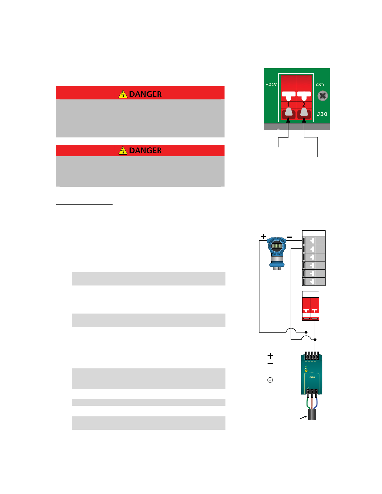
The DM22x needs to be powered by an externally supplied 12-24
VDC power supply (Pmax = 6W).
All electrical installation and maintenance work must
be undertaken by a qualified electrician only. The
Safety Instructions in this Installation and Operation
Guide must be followed. Failure to do so will result in
serious injury or death.
Power and Relay must be wired using acceptable
Class I Division 2 wiring methods if the hazardous
area rating is to apply. Failure to do so could result in
serious injury or death.
POWER CONNECTION
Installation steps to be performed are:
3. All terminal blocks are labeled and color coded:
Power (J30) – RED
Analog Inputs (J32) – LIGHT GREY
Digital Inputs (J34) – DARK GREY
Relay Output (J35) – BLUE
NOTE - Relay Output can be configured as NO or NC and
rated at max 0.5A at 125VAC, 2A at 30VDC
4. Inside the terminal side of the Data Monitor there are 3
screws provided for shielding and grounding of the unit for
saftey.
NOTE – For ground shield two (2) #4-40 screws are
provided and for Tie down one (1) #8-32 screw is provided.
5. If analog inputs are used, connect the analog input shield
to the DM22x enclosure #4-40 shield screw (see diagram).
For analog and digital inputs wiring use shielded 22AWG,
300V cable with minimum temperature rating of -20C to
80C.
NOTE – Analog inputs are not optically isolated. If
necessary, use universal signal conditioning module (P/N
A08968A) for each analog input.
NOTE – Digital inputs are non-powered dry contact type.
NOTE – Terminal connection diagram is also provided on
the back-side of the DM22x front cover for reference.
12-24V
DC
DC Common
Power Connections on DM
Terminal
J32
Terminal Block
AI 1 +
6
AI 1 -
5
AI2 +
4
AI 2 -
3
AI3 +
2
AI 3 -
1
J30
Terminal Block
+ 24
GND
VDC
2
1
= +24Vdc
= Ground
= Ground
N = Neutral
DC ok
24 -28V
Power Supply
100-240Vac 1.0A
NL
DC
ok
50W
L = Live
110-240Vac
Single Power Supply for Process
Transmitter and Data Monitor
Page 22
Page 23

ProSmart Installation & Operation Guide
DATA MONITOR INSTALLATION
6. Install the conduit and connection box per your local
electrical and environmental codes.
7. DM22x has ¾" NPT conduit hub.
8. Use a voltmeter to measure the supplied power at the
connection box and verify that it is within the 12-24VDC
range.
NOTE – Before powering the DM22x take every precaution
to ground the unit.
The Data Monitor does not have an on-off
switch and will start operating as soon as
power is applied. This may result an
unintended alarm annunciation as well as an
unintended activation of Relay Outputs on
the Data Monitors communicating with the
Communication Module at the time. To
ensure the relay activates only when desired,
do not connect the Data Monitor relay wires
until the system accepting the contact closure
is ready (alarm beacon, horn, etc.).
9. After completing the electrical connection, fasten the
DM22x front cover.
NOTE – The DM22x is delivered with protective caps on all
connectors. The caps shall remain in place on all
connectors that do not have a sensor cable connected.
Failing to follow this instruction may lead to damage of the
connector and subsequent damage to the internal
electronic boards.
DC ok
24 -28V
Power Supply
100-240Vac 1.0A
NL
DC
ok
50W
N = Neutral
= +24Vdc
= Ground
= Ground
L = Live
110-240Vac
Separate Power Supply for Process
Transmitter and Data Monitor
A08968A
1
2
3
7
8
9
10
11
12
DC
ok
DC ok
24 -28V
Power Supply
100-240Vac 1.0A
NL
50W
= +24Vdc
= Ground
6
5
4
3
2
1
6
5
4
3
2
1
Terminal Block
+24
VDC
1
J32
Terminal Block
J32
Terminal Block
J30
GND
DC ok
24 -28V
Power Supply
100-240Vac 1.0A
NL
AI 1 +
AI 1 -
AI 2 +
AI 2 -
AI 3 +
AI 3 -
AI 1 +
AI 1 -
AI 2 +
AI 2 -
AI 3 +
AI 3 -
2
DC
ok
50W
Page 23
= Ground
N = Neutral
L = Live
Universal Signal Conditioning
Module Wiring
Page 24

ProSmart Installation & Operation Guide
DATA MONITOR INSTALLATION
3
For hazardous areas classified as Class I Division 2 Group A B C D
T4, Cap Lock (P/N A08569A) should be used on all plug and play
connections of the Data Monitor, whether there is a sensor
connected or only a protective screw cap, to prevent the event of
an open receptacle.
Class I Division 2 Cap Lock Installation
Unit must have tool removable cap-locks installed
according to Installation and Operation manual or the
system is not Class 1 Division 2 compliant. Failure to
comply with Class 1 Division 2 instructions could
result in serious injury or death.
CapLocks are to be used on the following areas for Class 1
Division 2 applications:
A. DM22x connections (includes unused inputs).
B. Cable to cable connection points.
C. Sensor cable to sensor housing connection.
1
C
2
!
k
c
i
l
Page 24
3
Page 25

ProSmart Installation & Operation Guide
DATA MONITOR INSTALLATION
Cap Lock Install: DM22x Connections
For hazardous areas classified as Class I Division 2 Group A B C D
T4, Cap Lock (P/N A08569A)
Installation steps to be performed to install Class I Division 2 caps
are:
1. Unit should not be powered until all Cap Locks are
installed and the installation is compliant with Class 1
Division 2 and local electrical standards.
2. Cover the installed sensor, extension cable connection, or
protective screw cap with the Class I Division 2 Cap Lock.
3. Connect the 2 halves of the cap lock around the
connection point. After it snaps together secure the cap
lock to the cable (if applicable) by inserting the arrow
through the ring.
TACH V/T-1
V/T-2
A
B
C
For Non-hazardous
TACH V/T-1
V/T-2
Page 25
For C1D2 Rated
TACH V/T-1
V/T-2
Page 26

ProSmart Installation & Operation Guide
s
1
D
d
DATA MONITOR INSTALLATION
Cap Lock Install: Cable to Cable Connections
For hazardous areas classified as Class I Division 2 Group A B C D
T4, Cap Lock (P/N A08569A)
Installation steps to be performed to install Class I Division 2 caps
are:
1. Unit should not be powered until all cap-locks are
installed and the installation is compliant with Class 1
Division 2 standards.
2. Cover the cable connections with the Class I Division 2
Cap Lock.
3. Connect the 2 halves of the cap lock around the
connection point. After it snaps together secure the cap
lock to the cable (if applicable) by inserting the arrow
through the ring.
4. Each connector requires a Cap Lock, therefore cable to
cable connections will have 2 Cap Locks.
TACH V/T-1
V/T-2
A
B
C
For Non-hazardou
For C
Page 26
2 Rate
Page 27

ProSmart Installation & Operation Guide
d
DATA MONITOR INSTALLATION
Cap Lock Install: Cable to Sensor Connections
For hazardous areas classified as Class I Division 2 Group A B C D
T4, Cap Lock (P/N A08569A)
Installation steps to be performed to install Class I Division 2 caps
are:
1. Unit should not be powered until all cap-locks are
installed and the installation is compliant with Class 1
Division 2 standards.
2. Cover the installed sensor connection with the Class I
Division 2 Cap Lock.
3. Connect the 2 halves of the cap lock around the
connection point. After it snaps together secure the cap
lock to the cable (if applicable) by inserting the arrow
through the ring.
TACH V/T-1
V/T-2
A
B
C
For Non-hazardous
For C1D2 Rate
Page 27
Page 28

ProSmart Installation & Operation Guide
DATA MONITOR INSTALLATION
This page was intentionally left blank.
Page 28
Page 29

ProSmart Installation & Operation Guide
SENSOR INSTALLATION
SENSOR INSTALLATION
This section is devoted to install your ProSmart Sensors ST-02 and
SV-03.
Step Description
1
2
Sensor Overview
Tachometer Sensor
ST-02 Overview and Considerations
ST-02 Installation
Vibration & Temperature Sensor
SV-03 Overview and Considerations
SV-03 Installation
MK-04
Page 29
Page 30

ProSmart Installation & Operation Guide
SENSOR INSTALLATION
1
Tachometer Sensor
ST-02 OVERVIEW AND CONSIDERATIONS
The Tachometer ST-02 is a high quality inductive proximity
sensor. An inductive proximity sensor operates by measuring the
oscillator circuit losses of a projected electromagnetic field.
Inductive proximity sensors use an oscillator to generate an
electromagnetic field that radiates from the sensor’s tip. When a
metal object enters this field, surface currents, called “eddy
currents”, are induced in the metal object. These eddy currents
drain energy from the electromagnetic field resulting in a loss of
energy in the oscillator circuit. This in turn leads to a decrease in
the amplitude of oscillation. A trigger circuit monitoring the
oscillator mechanism detects this change and generates a signal
that switches the output ON or OFF. When the object leaves the
electromagnetic field area, the oscillator eddy currents subside
and the oscillator regenerates. Returning the sensor returns to its
OFF state.
The ST-02 tachometer provides a voltage pulse output
proportional to shaft speed. During each rotation of the shaft, a
raised metal component passes the sensor face and triggers a
voltage pulse. The raised metal target must be ferrous. For
optimal sensing range, a carbon steel target is recommended.
NOTE – The ST-02 can be used to detect a detent or shaft keyway.
The depth and width of the indent and shaft material will
determine if the ST-02 can sense the change.
An LED on the sensor housing will illuminate when the sensor is
triggered. See the diagram shown to the right for LED location.
Target
Distance
5mm
1
2
Tachometer sensor
over Shaft-Key
Typical Coupling
Hub
Shaft-Key
Typical Rotating Shaft
ST-02
Page 30
Page 31

ProSmart Installation & Operation Guide
SENSOR INSTALLATION
ST-02 INSTALLATION
During installation all equipment must be
disconnected from the power supply without any
possibility of being made live (Lockout/Tagout).
The Safety Instructions in this Installation and
Operation Guide must be followed. Failure to do
so will result in serious injury or death.
Installation steps to be performed are:
1. Inspect both the driving and driven machine around the
coupling or shaft to determine an appropriate location for
the tachometer mounting bracket. The bracket requires a
flat surface oriented 90° from the shaft. The bracket
should also be stiff enough to avoid bouncing during
machinery operation.
2. A ferrous metal target is required for the sensor to detect.
Either a shaft-key, shaft keyway, or a set screw is
acceptable. ITT also has special order split aluminum rotary
encoders for purchase which make for easier installation.
3. Once a suitable mounting location is identified, verify that
the sensor cable will reach the Data Monitor and will not
interfere with the operation and maintenance of the
desired monitored equipment.
4. Bolt one end of the mounting bracket to the machine just
above the shaft target.
5. Adjust the other end of the mounting bracket to align with
the centerline of the shaft. Refer to the diagram shown
below for proper installation and typical dimensions.
6. Thread the top nut and star washer onto the tachometer
housing. Leave enough of the sensor housing below the
top nut so that the sensor can be inserted fully through the
bottom hole in the mounting bracket.
7. Using the top nut, adjust the sensor so that the gap
between the sensor face and the top of the shaft key is
between 0.197” (5mm) and 0.157” (4mm). Refer to the
diagram shown below for proper installation and typical
dimensions.
8. Secure the tachometer sensor to the bracket by threading
the bottom nut and star washer.
9. Plug the tachometer sensor cable into the Data Monitor
into the TACH connector. Do not force to connect any
cable connection; it may lead to damage the Data Monitor
and/or the sensor connection cable.
10. If system is in a Class 1 Division 2 environment install cap
locks in correct locations as described in previous capture.
6
8
Page 31
Page 32

ProSmart Installation & Operation Guide
SENSOR INSTALLATION
11. Once cap locks are properly installed and all wiring and
installation is compliant with the plant and local codes,
power the DM22x ON.
12. Rotate the machine shaft by hand while watching the LED
on top of the tachometer sensor. Ensure that LED is on
when the target is under the sensor and off when the
target is not. If the LED does not light, adjust the gap until
the LED lights up during the appropriate times.
13. Tighten the bottom nut and ensure that the sensor does
not drift from its working location. If the sensor goes out
of the gap sensing area, no reading will be taken.
14. Verify the proper installation and operation of each sensor
by viewing the sensor readings on the ProNet User
Interface. Consider using Loctite 243 on threads to avoid
loosening of nuts.
12
Page 32
Page 33

ProSmart Installation & Operation Guide
SENSOR INSTALLATION
2
VIBRATION & TEMPERATURE SENSOR
SV-03 OVERVIEW AND CONSIDERATIONS
Accelerometers are the industry standard transducer for vibration
analysis systems. They output electrical signals in response to
mechanical accelerations. Acceleration is typically used to
measure vibration levels on rolling element bearing housings.
Typical accelerometers output an analog waveform scaled in mV /
G. G’s are the units of acceleration used in vibration analysis (1 G
= 9.8m/s
The SV-03 sensor is a MEMS (Micro Electro-Mechanical) type
accelerometer and as such can not be powered using standard
Piezo accelerometer power supplies. The SV-03 is also a “matched
system component” and can not
standard 100 mV/G sensors. Any attempt to do so may
damage both the sensor and the ProSmart Data Monitor.
SV-03 MOUNTING CONSIDERATIONS
Vibration Sensor
2
and 32.2 ft/s2 ).
be replaced by or substituted for
1. The key to accurate vibration measurement and
condition diagnosis is transducer placement.
Accelerometers should be mounted at points that are
most responsive to changes in machine condition.
2. Accelerometers must be mounted as close as possible to
the machine’s bearings to ensure that vibrations are
transmitted directly to the sensor. Any mechanical
impedance between the sensor and the bearing housing
will decrease the accuracy of the measured vibration.
Never mount an accelerometer on heat shielding or
machine guards. Acceptable locations for mounting the
SV-03 are shown on the diagram to the right.
3. When mounting accelerometers in the axial direction, the
sensor must be located in the “load zone” of the bearing.
This zone is normally directly beneath the rolling element
bearing. However, on certain belt or chain driven
equipment, the load zone can shift. Consult a ProSmart
applications engineer if unsure of proper mounting
locations.
4. Thrust Bearings are designed to primarily handle axial
forces. To best monitor thrust bearings, axial mounting
of the sensor is suggested. Although the SV-03 can
monitor the thrust force while mounted in any position,
it gives the most accurate representation of machine
vibration in the axis that is aligned with. This is because
the sensor only has to contend with translational motion
(straight line) in that axis. The other axis will contain a
small portion of rotational motion (rocking) as well.
Bearing
Housing
1
2
Axial (Z-Axis)
SV-03
Vertical
(Y-Axis)
Horizontal
(X-Axis)
Page 33
Page 34

ProSmart Installation & Operation Guide
SENSOR INSTALLATION
5. The orientation of the sensor must be recorded. The
names of each axis on the ProNet User Interface must
then be adjusted to reflect the machinery axis being
measured. For example, if the Z-Axis (denoted by the
groove on the body of the sensor) is typically placed in
line with the machine axial plane and preferably facing
the driven end of the equipment. This will ensure that
the data is properly interpreted by the end user.
Temperature Sensor
The SV-03 includes an integrated temperature sensor. The
temperature sensor can provide valuable data related to rolling
element bearing condition. For the most accurate temperature
readings, the sensor must be mounted as close as possible to the
bearing housing. There will most likely be a small differential
between measured skin temperatures and the SV-03’s measured
value. Temperature trending will provide indications of changes
in machine condition, even if the measured temperature at the
sensor is different from the skin temperature of the bearing.
Drive
End
Vertical
l
a
i
x
A
t
f
ha
S
Preferred Sensor
Orientation
NonDrive
End
H
o
r
i
z
o
n
t
a
l
Page 34
Page 35

ProSmart Installation & Operation Guide
SENSOR INSTALLATION
MACHINE SPECIFIC CONSIDERATIONS
Bearing Location Terminology
ITT uses standard terminology to describe the locations of
bearings on equipment. Drive End denotes the bearing that is
located closest to or connected to the powered shaft. Non Drive
End denotes the bearing that is farthest from the powered shaft.
Refer to the diagrams shown to the right.
NOTE – Although the default terminology refers to Drive end and
Non drive end the sensors can be named to the customer’s
preference. Inboard/outboard or thrust/radial are also acceptable
bearing terminology.
Pumps
Horizontal Pumps
Optimal monitoring positions for Pumps are on both bearings on
the power end of the pump. This includes Overhung and
Centerhung (AKA “between bearings”).
Goulds pumps will have an indent above the bearings where a
vibration sensor is to be located.
Always mount the sensors over the flange on the power end,
never on the hollow section of the casting.
Vertical pumps
Most vertical pumps do not have easily accessible pump bearings.
In this application the best location for vibration monitoring will
be isolated to the motor. Some prefer to also have monitoring on
the stuffing box bushing. This may pick up vibrations transmitted
to the casing.
AC/DC Motors
Optimal monitoring positions for AC/DC motors are at the drive
end and opposite drive end bearing locations.
If a motor’s cooling fins prevent tapping a hole for sensor
mounting, a Fin Mount adapter can be epoxied in between the
motor fins just above the bearing. The sensor can then be
threaded into an MK-04 adapter and affixed to the Fin Mount
adapter.
NOTE – Never mount an accelerometer on the Fan Cover of a
motor. The fan cover does not provide an adequate transmission
path for the vibration and any sensor readings recorded on them
will not represent actual machinery vibration.
NON DRIVE END
DRIVE END
Bearing Locations
DRIVE END NON DRIVE END
DRIVE END
NON DRIVE END
Bearing Locations
Page 35
Page 36

ProSmart Installation & Operation Guide
SENSOR INSTALLATION
Fans
Optimal monitoring positions for Axial and Radial Flow fans are at
the drive end and opposite drive end bearings.
Certain Belt driven fans may have a bearing load zone that is not
directly beneath the bearing. If unsure of proper mounting
location for axial sensor mounting on this type of equipment,
consult a ProSmart Applications Engineer.
Belt /Chain Driven Equipment
If the 2 shafts connected by the belt are not in the same plane,
the radial mounting positions are not at true vertical and
horizontal positions. The mounting positions must be adjusted in
order to better detect the bearing and belt defects on machines
with this configuration. Refer to the diagram shown to the right
for proper mounting locations. Either of the X or Y positions are
appropriate for mounting the SV-03 Tri-axial sensor.
Horizontal (X-Axis)
Vertical (Y-Axis)
MACHINE SPECIFIC CONSIDERATIONS
Blowers, Compressors
Optimal monitoring positions for Axial Flow and Radial Flow
blowers are at the drive end and opposite drive end bearings.
Reciprocating Equipment
Optimal monitoring positions for standard (2 bearing)
reciprocating machinery are at the drive end and opposite drive
end bearing locations.
If there are more than 2 bearings on the crankshaft, each bearing
location should be monitored in order to adequately protect the
machine.
Rolls
Due to the lower RPM of rolls be sure to consult with a ProSmart
Applications Engineer on possible limitations. ProSmart will only
currently sample down to 6 Hz. With low speed applications this
may miss the 1x run speed vibration but in most cases is sufficient
to monitor bearing failures.
Oil/Lube Based Bearings (Babbitt, sleeve, journal etc.)
ProSmart uses an accelerometer to detect bearing faults and
machine health. Since oil/lube based bearings do not contain
rolling elements mechanical motion is not transferred to the
machine. Larger rotating equipment tends to use oil/lube based
bearings. Lube base bearings need to be monitored with an “Eddy
Current Probe” or “Displacement Transducer” (aka Proximity
Probe). These sensors can be brought into ProSmart as an overall
value through the 4-20mA connection. This will measure the
clearance between the shaft and the sensor.
Belt/Chain Driven Equipment
Page 36
Page 37

ProSmart Installation & Operation Guide
SENSOR INSTALLATION
SV-03 PRE-INSTALLATION
1. Before installing the SV-03 Sensor, identify bearing
locations on each machine to be monitored. Record
locations on a machinery diagram for future reference.
NOTE – Sensors should not be mounted in environments
exceeding 190°F.
2. If it is desired to mount the sensor using a 1/4-28 stud
instead of the standard ¼ NPT threads, a Mounting
Adapter is available. Reference part number A08560A.
3. For epoxy mounting using the MK-04 adapter kit, the
mounting locations should first be scraped free of paint
and cleaned of oil and grease. Any material such as these
will attenuate the vibration readings if it is between the
sensor and the machine. Grease, dirt, and loose paint will
cause the epoxy to not adhere properly.
4. For temporary mounting a magnetic mount solution is
available. The magnetic mount has a ¼-28 UNF stud that
screws into the MK-04. The magnet mount is a rare earth
flat magnet.
5. If mounting the MK-04 adapter on a curved or irregular
surface, such as on the side of a motor, for best results the
mounting location should be spot faced to provide a 1.25
inch diameter flat area.
SV-03 INSTALLATION
Y
Z
X
¼” NPT
0.44" TYP1.00"
Axial View
Y
X
During installation all equipment must be
disconnected from the power supply without any
possibility of being made live (Lockout/Tagout).
The Safety Instructions in this Installation and
Operation Guide must be followed. Failure to do
so will result in serious injury or death.
1. Locate an appropriate location such as above a rolling
element bearing to install the SV-03 sensor. Before
installing the sensor cable, verify that the cable will reach
the Data Monitor and will not interfere with the operation
and maintenance of the equipment. Extension cables are
available if needed to ensure proper cable routing.
2. A ¼” NPT tapped hole is needed for installation of the SV03 sensor. Mark the position of the hole on the desired
equipment to monitor.
3. Drill and tap a ¼” NPT hole. Do not break through the
casting of the bearing frame. Take extra caution not to
leave any metal particles in the hole as this may affect
vibration and temperature sensing.
4. Apply thermal conductive thread sealant – Loctite 243 to
the threads of the SV-03 sensor.
¼” NPT
Side View
Bottom Drill
¼” NPT
Z
1.00"
0.44" TYP
Page 37
Page 38

ProSmart Installation & Operation Guide
SENSOR INSTALLATION
5. Thread the SV-03 sensor into the tapped hole. The
preferred orientation of the sensor slot (denoting the Z –
axis) is facing either the drive end (preferred) or the non
drive end (alternative). This is critical to ensure that the
correct vibration readings are recorded for X, Y, and Z axis.
6. The Data Monitor should be powered down before
plugging in the sensor. This will avoid false spikes of data
when the sensor is connected.
7. Plug the SV-03 sensor cable onto the sensor and then into
a V/T receptacle on the Data Monitor. The connectors are
keyed and only connected in one orientation. Do not use
force when connecting the sensor cables to the Data
Monitor since this may damage the Data Monitor and/or
the cable connector. The connector with more pins is
connected to the sensor and the connector with fewer pins
is connected to the Data Monitor.
NOTE – Do not power on the Data Monitor until all sensors
are properly installed and connected to the Data Monitor.
Connecting a sensor to a powered DM can cause a voltage
spike that may harm the sensor.
8. Ensure that the sensor cable is secured after mounting so
that it does not move or flex continuously during
machinery operation.
9. Verify the proper installation and operation of each sensor
by viewing the sensor readings on the ProNet User
Interface.
MK-04
Epoxy Mounting –
Installation steps to be performed are:
1. A 1.25” minimum diameter is needed to install the MK-04
mounting adapter.
2. Apply thermal conductive thread sealant – Loctite 243 to
the threads of the SV-03 sensor. Loctite 243 is provided
with your MK-04 package.
3. Thread the SV-03 sensor into the ¼” NPT tapped hole of
the MK-04. Secure the MK-04 to sensor by using a 9/16”
wrench on the sensor and channel locks on the MK-04. DO
NOT over tighten, the Loctite 243 will ensure that the
sensor does not become loose due to vibration.
a. The location of the sensor determines the way a
unit can be monitored. Ideally the sensor will be
mounted as close to the bearing housing as
possible and oriented in the proper direction.
b. The equipment surface needs to be cleaned and
free of heavy dirt, paint, oil, and grease.
c. A wire-brush or grinding wheel works well for
removing rust and paint. Make sure area is safe
for hot work.
Epoxy Mounting
Page 38
Page 39

ProSmart Installation & Operation Guide
SENSOR INSTALLATION
4. The mounting adapter comes with a Loctite 330 Kit
(Epoxy). Crush the activator vial between your fingers.
Using the cotton tip wet the surfaces that will be in contact
with the Epoxy.
5. Break off the tip of the epoxy tube and apply the adhesive
to the bottom of the mounting adapter. You can use the
activator vial to spread the Loctite 330 on the mounting
adapter. Follow instructions and recommended cure time
on back of the Loctite 330 package.
6. Make sure that the notch on the sensor is pointed along
the axis of the machine; either towards the back end of the
motor (drive end - preferred) or towards the far side of the
driven equipment (non drive end - alternate). Press and
hold the mounting adapter to the equipment for
approximately 4 minutes (longer if conditions require). The
full cure takes 4-24hours.
Page 39
Page 40

ProSmart Installation & Operation Guide
SENSOR INSTALLATION
Stud Mounting –
Installation steps to be performed are:
1. A 1.25” diameter is needed to install the MK-04 mounting
plate. Mark the desired area for the mounting plate and
use spot face tool to level and clean the area.
x A ¼”-28 UNF tapped hole is needed for MK-04
mounting stud. If a ¼”-28 UNF hole does not
already exist, mark the position for the stud on
the desired equipment to monitor and drill and
tap accordingly.
x Apply thermal conductive thread sealant –
Loctite 243 to the threads of the mounting stud.
Loctite 243 is provided with your MK-04 order
package. Follow instructions on back of the
Loctite 243 package.
2. Thread the mounting stud into the ¼”-28 UNF hole
identified in step 1 above.
3. Apply Loctite 243 to the remaining threads of the
mounting stud.
4. Thread the mounting plate onto the mounting stud. Gently
hand tighten. Leave some slack to correct for orientation.
5. Thread the SV-03 sensor into the ¼” NPT tapped hole of
the MK-04. Using a 9/16” wrench on the sensor tighten the
sensor and MK-04 together. DO NOT over tighten, the
Loctite 243 will ensure that the sensor does not become
loose due to vibration.
Stud Mounting
x Make sure that the notch on the sensor is
pointed along the axis of the machine; either
towards the back end of the motor (drive end preferred) or towards the far side of the driven
equipment (non drive end - alternate).
x If it is not possible to get the sensor in the
preferred orientations be sure to get the
orientation 90 degrees from the preferred
orientation.
6. Follow SV-03 installation instruction from steps 6 through
step 9.
Page 40
Page 41

ProSmart Installation & Operation Guide
SENSOR INSTALLATION
Magnet Mount –
Installation steps to be performed are:
1. A 1.25” diameter is needed to install the MK-04 mounting
plate with the magnetic adapter. Mark the desired area for
the mounting plate and use spot face tool to level and
clean the area.
x Apply thermal conductive thread sealant –
Loctite 243 to the threads of the magnetic
adapter and threads of the sensor. Follow
instructions on back of the Loctite 243 package.
Loctite 243 is provided with your MK-04 order
package.
2. Thread the magnetic adapter into the ¼”-28 UNF hole
identified in step 1 above.
3. Thread the SV-03 sensor into the ¼” NPT tapped hole of
the MK-04. Using a 9/16” wrench on the sensor and
channel locks on the MK-04 tighten the sensor and MK-04
together. DO NOT over tighten, the Loctite 243 will ensure
that the sensor does not become loose due to vibration.
4. Place the sensor on a ferrous surface. Make sure that the
orientation is correct. The preferred orientation of the
sensor slot (denoting the Z – axis) is facing either the drive
end (preferred) or the non drive end (alternative). This is
critical to ensure that the correct vibration readings are
recorded for X, Y, and Z axis.
5. Follow SV-03 installation instruction from steps 6 through
step 9.
Page 41
Magnet Mount
Page 42

ProSmart Installation & Operation Guide
SENSOR INSTALLATION
This page was intentionally left blank.
Page 42
Page 43

ProSmart Installation & Operation Guide
PRONET USER GUIDE
PRONET USER GUIDE
This section is devoted to the ProNet Graphical User Interface.
Step Description
ProNet User Guide
Logging into ProNet
Dashboards
My Machines
Data and Trending
Analytical Features
Page 43
Page 44

ProSmart Installation & Operation Guide
PRONET USER GUIDE
1
LOGGING INTO PRONET
GETTING STARTED
Browser Requirements: Internet Explorer v6+
The recommended display resolution is: 1280 x 1024 pixels
Right-click Desktop
DPI Setting: Normal Size (96 DPI)
Right-click Desktop
Website:
http://www.ittmc.com
Login:
Your user name and password will be provided to you when your user count is activated. If you haven’t
already received the user name and password, please inform your local sales contact or call
1-866-261-5612 and Press 3.
Æ
Properties / Settings
Æ
Properties / Settings / Advanced / General
OR https://www.prosmart.ittmc.com
2
3
4
5
Page 44
Page 45

ProSmart Installation & Operation Guide
PRONET USER GUIDE
WELCOME TO PRONET
Once you have successfully logged into ProNet, you will typically be greeted by the ProNet Welcome
screen. This screen serves as your gateway to online monitoring and includes some key features. You may
also be greeted by a dashboard screen. Company Administrators can configure the rules for the users in
that company.
Overview
Overview
Your primary selection for viewing and
Your primary selection for viewing and
maintaining ProSmart devices. Choices:
maintaining ProSmart devices. Choices:
- Dashboards
- Dashboards
-My Machines
-My Machines
-My Reports
-My Reports
Administration
Administration
Administration allows you to add users,
Administration allows you to add users,
define companies and/or operating
define companies and/or operating
units, as well as administer different
units, as well as administer different
machine types.
machine types.
Page 45
News and Notes
News and Notes
This area is used to inform you of new
This area is used to inform you of new
features, platform status, and other
features, platform status, and other
information beneficial to your use of
information beneficial to your use of
ProNet.
ProNet.
Page 46

ProSmart Installation & Operation Guide
PRONET USER GUIDE
DASHBOARDS
ProSmart continuous machinery monitoring system is designed for multi-plant predicitive
maintenance programs.
ProNet Dashboards take the abstract nature of your machine data and ties it into a visual
representation of your machine. ProNet utilizes an easy to understand graphis to help quickly
vizualize the condition of each machine. From ‘Green-on-Green’, meaning everything is okay to
‘Red-on-Red’ to indicating an active alarm state.
1
2
3
4
5
Above is a typical layout for a customized Equipment Level Dashboard. The dashboard display and
breaks out the sensors. If you hover your mouse over the sensor a “Quick View” window will appear
(sample shown below). The “Quick View” trends 2 weeks worth of data to give you a quick glance at
how the equipment has been operating.
Page 46
Page 47

ProSmart Installation & Operation Guide
PRONET USER GUIDE
ALARM SUMMARY ICON
Next to each sensor name there is a colored bulls-eye (as shown at the bottom). The bulls-eye represents
the machine’s health for that particular sensor.
Current Level
Inner Ring
Alarm State
Outer Ring
Current Level –
The current state of the machine acts as real time alarming. If the machine is in alarm
this circle is showing red. If it is at an acceptable vibration level then it is green.
Alarm State –
The Alarm State acts as an alarm historian. If a sensor reaches an alarm threshold and
will maintain the worst alarm state color until it is acknowledge by a user.
For the example shown below the equipment has warnings and alarms. The inner circle represents the
current state of the machine. The outer circle represents the alarm state. In the example above the “Motor
Outboard – Z axis” shows the outer circle red and the inner circle green; this means that the machine’s
current operation in with the set limits but was previously in an alarm condition. The key below shows the
possible combinations and their meanings.
Page 47
Page 48

ProSmart Installation & Operation Guide
PRONET USER GUIDE
BREADCRUMBS
The Dashboard “Breadcrumbs” feature of ProNet allows the user to easily navigate back to previously
viewed pages. The Dashboard link will always be available to quickly take the user to the primary
dashboard. The “Scroll Link” will be active if the number of dashboard tabs exceeds the page width.
TRENDING DATA
Trending data can be easily done from the dashboard. Simply click the empty check box next to the
desired sensor (multiple sensors can be selected) and then click the “Trend Selected” button. Users who
want to see a vibration sensor trend with FFT event icons (when an FFT was captured) can select the trend
icon to the right of the sensor; for all other sensor types this icon will pull up a trend only.
Alarms are able to be acknowledged directly from the dashboard by clicking on the sensor “bulls-eye”.
Page 48
Page 49

ProSmart Installation & Operation Guide
PRONET USER GUIDE
MACHINE NOTES
“Machine Notes” is available to customers that purchase a customized dashboard. This feature allows
users to post comments about the machine, alarm conditions, and other maintenance related activities.
The user types a comment into the lower text box (see picture below) and then clicks “Enter Comments.”
The comment will then become displayed in the upper text box for future users to see. The Machine Notes
can double as a maintenance log and can be exported into excel for record keeping.
Page 49
Page 50

ProSmart Installation & Operation Guide
PRONET USER GUIDE
1
MY MACHINES
The My Machines page houses more information than the dashboards, which is why this page
makes use of lists and tabs to organize information. When you trend sensors you are
automatically navigated to the My Machines page.
TABS AND RELATED FUNCTIONS
Additional information about selected machine
SENSORS – Provide listing of all physical sensors of selected machine
BAND SENSORS – Provide listing of all band (aka window) sensors of selected machine
TREND – Window for viewing selected sensor data
SPECTRUM – Window for viewing selected FFT/Time Waveform data
BAND ALARMS – Graphical view of a machines band sensors (aka window sensors)
MACHINE INFO – Information regarding machine and alarm acknowledgements
2
3
4
5
Page 50
Page 51

ProSmart Installation & Operation Guide
PRONET USER GUIDE
MACHINES TAB
The My Machines page is the list view of equipment. It displays the machine name, the importance level,
alarm summary icon, the machine type, and the company it resides under.
The machines are automatically sorted by importance and alarm levels. Machines are first sorted by a user
defined importance level, by the alarm state, and then by current operation state. This will allow you to
rapidly sort through machines and sensors to find critical data.
.
Page 51
Page 52

ProSmart Installation & Operation Guide
PRONET USER GUIDE
SENSOR TAB
Selecting the machine’s name from the Machine tab will open the Sensors tab. This will display available
sensor groups and sensor values. Sensor data can be trended, spectrum data viewed, and sensor readings
requested from this single page.
This page displays:
x Sensor description
x Sensor last recorded value
x Unit associated with sensor reading
x Last time the sensor value was recorded
x Alarm Icon
x Trending and Data Request Icons
NOTE – If the machine time is greater than 8 hours old, the sensor may be disabled or the DM is not
reporting. If sensor value is “---“, it means the DM has stopped communicating with the platform. It
is recommended to check power on CM and DM.
Page 52
Page 53

ProSmart Installation & Operation Guide
PRONET USER GUIDE
Trending & Requesting Data
Icons on the right side of the screen are used for trending and requesting data (as shown below).
REQUEST FFT/TWF – Request an FFT and/or Time Waveform to be taken
VIEW LAST FFT/TWF – Plot FFT and/or Time Waveform data
READ – Request a sensor reading to be taken
TREND – Plot sensor data against time
To trend data from the Sensors tab, select the desired sensor by clicking on the empty box at the right
side of the screen. Once all the desired sensors are selected, click the icon to view the graph of the
trends of the selected sensor(s).
Page 53
Page 54

ProSmart Installation & Operation Guide
PRONET USER GUIDE
MACHINE INFO TAB
The Machine Info tab contains:
x The DM name, DM’s MAC ID, & Company
x Last communication time
x Importance level
x Machine type
x Bearing information (BPFO, BPFI, BSF, FTF)
x Machine Notes (Record of cleared alarms and comments.)
Alarm Acknowledgements
When an alarm is cleared a note will be made of what alarm was cleared, by whom, and at what time.
User Comments
A user can add comments to a machine or sensor. First a user must select the area they would like to
comment on
Then type the comment into the text field.
Then click
The comment will appear to the right of the text field
Page 54
Page 55

ProSmart Installation & Operation Guide
PRONET USER GUIDE
Data And Trending
TYPES OF DATA
Overall Vibration
Overall is calculated as a Root-Mean-Squared (RMS) value.
Fast-Fourier Transform (FFT)
ProSmart has the ability to analyze the time-waveform data collected from a vibration sensor
using a Fast-Fourier Transform (FFT) Analysis in RMS (ips). Users are able to view the FFT value in
Velocity (ips), Acceleration (g), and Displacement (mils)
x On Alarm – When a sensor goes into an alarm condition, ProSmart can be
configured to automatically capture an FFT
x On Schedule – Automatic capture of FFT on calendar schedule
x On Request – On Demand
Time Waveform (TWF)
Users are able to view the raw data associated with a specific vibration spectral measurement.
This is also known as Time Domain Spectrum (TDS).
This is on Request Only
1
2
3
4
5
Page 55
Page 56

ProSmart Installation & Operation Guide
PRONET USER GUIDE
VIEW OPTIONS
The trending windows have 3 primary ways to view the data
1.
Graph is the graphical view of the data.
2.
Grid view is a list of all the data points that make up the graph. This is where you would go to export
the data points.
3.
Selection is essentially the graph legend where you can remove a trend line or change the axis it is
graphed on.
Page 56
Page 57

ProSmart Installation & Operation Guide
PRONET USER GUIDE
ALARM VALUES
ProSmart provides up to four alarm levels when monitoring data:
x High Alarm (Red Band)
x High Warning (Yellow Band)
x Low Warning (Yellow Band)
x Low Alarm (Red Band)
Alarm levels are set in the ProNet platform and then sent down to the Data Monitor. (Tip: Yellow band
represents warning and red band represents alarm thresholds)
Page 57
Page 58

ProSmart Installation & Operation Guide
PRONET USER GUIDE
ZOOM
Click on the graph to initialize the starting point of the area which will be zoomed in to.
While still holding the left mouse button, drag your mouse (left or right) and let go when you have
reached the end point of your desired zoomed in area.
x Select the icon to reset the zoom level.
x Select the icon enable zoom for x-axis only. (Default)
x Select the icon enable zoom for x- and y- axis
Page 58
Page 59

ProSmart Installation & Operation Guide
PRONET USER GUIDE
VIEWING HISTORICAL DATA
The date range selected can be changed from the top of the trend page. Orange calendar top indicates
the current selection. Week (7 days) is shown below as currently selected.
Quick Select Date Filters:
x 7 Day Trend (Default)
x 31 Day Trend
x 90 Day Trend
Custom Date Selection:
1. Click to edit date range. Once the Custom button is clicked the dates will be
editable.
2. Set date range manually OR Select range from popup calendars
3. Once you have set both dates click to activate the date range.
Page 59
Page 60

ProSmart Installation & Operation Guide
PRONET USER GUIDE
REMOVING TREND LINES
It is sometimes necessary to drop one or more trend lines from a graph while analyzing data. There are
two primary ways to remove trend lines from a graph.
1. To remove all the trend lines from a graph simply click on the icon which is
located near the upper right corner of the screen.
2. To remove only one sensor from the trend, go to the page and then click
for the sensor you would like to remove.
Page 60
Page 61

ProSmart Installation & Operation Guide
PRONET USER GUIDE
SECONDARY AXIS
The Secondary Axis feature is used to view different data sets at the same time. As you can see from the
screen shot below if temperature and vibration are graphed on the same axis, temperature will over
power the vibration reading because of the difference in scales.
It is necessary to move one of these data sets to a “Secondary Y-axis” in order to establish if there is a
correlation between vibration and temperature.
To set a trend to the “Secondary Y-axis” follow these steps:
1. Click on
2. Then click
3. Select
4. Click
5. Click
Page 61
Page 62

ProSmart Installation & Operation Guide
PRONET USER GUIDE
ANALYTICAL FEATURES
BAND ALARMS
(aka window sensors)
Band alarms (or windows) is a frequency span that covers particular fault frequency. This band sensor (or
window) is used to monitor the progression of a given fault.
There are 10 possible band sensors available per vibration axis. This means that there are 30 possible band
alarms per physical sensor and 120 band sensors per DM.
There are 2 ways to view the settings; the first is the list view of band sensors under the Band Sensors Tab.
1
2
3
4
5
The view shown below is a graphical view found under the Band Alarms Tab. User must select sensor they
wish to view from the drop down menu. This displays the alarm and warning levels as well as the current
value.
Page 62
Page 63

ProSmart Installation & Operation Guide
PRONET USER GUIDE
FFT EVENT ICONS
ProSmart will show when an FFT was taken for a trended sensor. This event icon will appear at the bottom
of the vibration trend. The icon also doubles as a link. When the icon is clicked, the user will be navigated
to the spectrum tab with the selected FFT displayed.
Page 63
Page 64

ProSmart Installation & Operation Guide
PRONET USER GUIDE
SPECTRUM DATA OPTIONS
Fast-Fourier Transform (Units)
• A - Acceleration (g’s)
• V - Velocity (inch/sec)
• D - Displacement (mils)
ProNet has the ability to make on-the-fly unit conversions to better meet the user’s preferences.
Multiple Viewing Options
ProNet can display FFT and Time Waveform on the same screen as well as individually to aid in rapid
diagnosis.
• Clicking “T” will toggle between three different graphing views
• FFT Only
• TWF Only
• FFT and TWF
Page 64
Page 65

ProSmart Installation & Operation Guide
PRONET USER GUIDE
HARMONIC CURSORS
Harmonic cursors are used as a tool in vibration analysis to eliminate possible fault conditions. Harmonic
cursors are used to distinguish synchronous and non-synchronous peaks as well as to view harmonics of a
frequency.
To use harmonic cursors:
1. Set the cursor base frequency. The cursors base frequency is typically the running frequency
(RPM/60) or the fundamental frequency of harmonics.
2. Then click
3. Click to Apply:
NOTE – The Width does not need to be set in order to use the harmonic cursors.
To remove cursors select
NOTE – The fields for cursor base frequency and width need to have a value otherwise you will not be
able to apply changes. If necessary set the fields to 0.
Page 65
and then select
Page 66

ProSmart Installation & Operation Guide
PRONET USER GUIDE
SIDEBAND CURSORS
Sideband cursors are used to distinguish peaks that appear next to a primary peak. This is another tool
used in vibration analysis.
To use sideband cursors:
1. Set the cursor base frequency. The cursors base frequency is typically the fault you want to view
for sidebands (typically bearing faults).
2. Then click
3. Set the side band width. This will set how far the sideband lines are apart from each other.
4. Click to Apply:
NOTE – The Width should be smaller than ½ of the cursor base frequency otherwise the sideband
markers will be hidden.
To remove cursors select and then select
NOTE – The fields for cursor base frequency and width need to have a value otherwise you will not be
able to apply changes. If necessary set the fields to 0.
Page 66
Page 67

ProSmart Installation & Operation Guide
PRONET USER GUIDE
WATERFALL VIEW
(aka 3D FFT view)
After several FFTs are selected on the same graph, click the 3D view on the graphing tool bar.
DATA EXPORT
Graphing data, spectrums, time waveform, and user comments can all be exported into excel.
1. If exporting User Comment Log go to step 3.
2. First select to view the data points on a graph or the data for a spectrum/waveform.
3. Then click the icon to export to Microsoft Excel.
4. A dialog box will pop-up (if using Internet Explorer).
If exporting graph data or spectrum/time waveform go to step 2.
If applicable: Click on either the FFT or the TWF to view the data points in the lower window.
Some Browsers may automatically start the download once icon is clicked.
5. Select save and save the data in a safe and accessible location.
Page 67
Page 68

ProSmart Installation & Operation Guide
PRONET USER GUIDE
This page was intentionally left blank.
Page 68
Page 69

ProSmart Installation & Operation Guide
APPENDIX A-1 MODBUS INFORMATION
Modbus Specifications
The Communication Module supports the FieldTalk™
Modbus/TCPIP slave functionality, which allows the ModbusTCP/IP master device to enquire data from the Communication
Module.
The Communication Module maps physical sensors - overall
vibration, temperature, tachometer, analog inputs, digital inputs,
and relay output readings from DM modules into a Modbus
registry space. Alarming and device management on ProSmart,
using Modbus, is not possible at this time.
NOTE – Communication Module does not poll the DM module
when the master requests a reading, but it uses the latest stored
value.
Modbus/TCPIP master and slave devices need to be on the same
LAN. Communication Module communicates via the standard
Modbus port 502.
Page 69
Page 70

ProSmart Installation & Operation Guide
APPENDIX A-1 MODBUS INFORMATION
This page was intentionally left blank.
Page 70
Page 71

ProSmart Installation & Operation Guide
APPENDIX A-2 PROSMART DATA SHEETS
Communication Module
Data Sheet
PROSMART
ProSmart CM
CERTIFICATIONS
RATINGS..…………………….…
RADIO
RADIO OUTPUT POWER………..200mW (B05686AXX, B06480AXX)
100mW (B05385AXX)
RADIO FREQUENCY……………..2.4GHz FHSS (Frequency Hopping Spread
ENVIRONMENTAL LIMITS
ENCLOSURE RATING………….……..NEMA 4X
ENCLOSURE MATERIAL...…………...Painted 304 Stainless Steel
HUMIDITY……………………...…….10-90% non-condensing
ENVELOPE DIMENSIONS……...…….20.0"H x 10.0'W x 5.5"D
WEIGHT………………………………15lbs (6.8kg)
STORAGE TEMP. MAX………….…..185°F (85°C)
STORAGE TEMP. MIN…………….…-40°F (-40°C)
COMMUNICATIONS
WIRELESS ARCHITECTURE………….Point-to-Multipoint
WIRELESS PROTOCOL…..……….….Proprietary Frequency Hopping Spread
DEVICE ENCRYPTION……...………..Up to 256-bit
GUI ENCRYPTION…………………...128 Bit SSL
GUI BROWSER……………………….Internet Explorer 7.0
TRANSMITTING RANGE………….…1.6 miles (2.5kM) Line of Sight
CSA, FCC, CE
CM LAN – Class I Division 2 Groups A B C D T4
CM GPRS – Non-Hazardous
CM-CDMA – Non-Hazardous
Spectrum)
(includes antenna)
Spectrum (FHSS) 2.4 GHz
655-1310ft (200-400m) Plant*
*depends on industrial environment
ProSmart CM-LAN
OP TEMP. RANGE………………..158°F (70°C) to -22°F (-30°C)
COMMUNICATIONS
NETWORK CONNECTION………..LAN or DSL
NETWORK PROTOCOL…………...Standard Ethernet
NETWORK ADDRESSING………...DHCP or Static IP
ELECTRICAL
SUPPLY VOLTAGE……………......12VDC
MAX. CURRENT DRAW.……...…..400mA
POWER CONSUMPTION……....…5W
ProSmart CM-GPRS
OP TEMP. RANGE…………….….131°F (55°C) to -8°F (-20°C)
COMMUNICATIONS
NETWORK CONNECTION………..GPRS Modem
(T-Mobile cellular data service)
NETWORK PROTOCOL…………...Standard Ethernet
NETWORK ADDRESSING………...DHCP
ELECTRICAL
SUPPLY VOLTAGE…………...…...12VDC
MAX. CURRENT DRAW.……...…..2A
POWER CONSUMPTION……....…24W
ProSmart CM-CDMA
OP TEMP. RANGE…………….….158°F (70°C) to -22°F (-30°C)
COMMUNICATIONS
NETWORK CONNECTION………..CDMA Modem
(Verizon cellular data service)
NETWORK PROTOCOL…………...Standard Ethernet
NETWORK ADDRESSING………...DHCP
Certified for Construction Purposes only when signed
Date……………………………………………………………..
Copyright 2011
ITT Corp.
No reproduction without
permission
Page 71
Drawing is not to scale
Dimensions in inches
ISSUE:
ELECTRICAL
SUPPLY VOLTAGE…………...…...12VDC
MAX. CURRENT DRAW.……...…..1A
POWER CONSUMPTION……....…12W
Customer Name…………………………………………………………….
Goulds S/N…………………………………………………………………..
Customer P.O #...............................................................................
Item No……………………………………………………………………….
Drawn: J. Sullivan
Checked:
Drawing
A05686A
Revision
0
Sheet
1 of 2
Page 72

ProSmart Installation & Operation Guide
APPENDIX A-2 PROSMART DATA SHEETS
ProSmart CM
Communication Module
Data Sheet
PROSMART
Cellular Antennas not
present in CM-LAN
OBLONG 0.31" x 0.50"
X 4 places
minimum required distance
3 ft
Communication Module
PROSMART
7.27
minimum required distance
3 ft
2.25
Copyright 2009
ITT Corp.
No reproduction without
permission
Page 72
12.7513.50
PROSMART
2.50
1.00
Front View
Drawing is not to scale
Dimensions in inches
Communication Module
8.00
10.00
ISSUE:
12.00
2.50
1.00
SS Slot Lock
SS Padlock
0.75
Drawn: J. Sullivan
Checked:
5.50
Side View
Drawing
A05686A
0.07
2.25
Revision
0
Sheet
2 of 2
Page 73

ProSmart Installation & Operation Guide
APPENDIX A-2 PROSMART DATA SHEETS
Data Monitor
Data Sheet
ProSmart DM22x
CERTIFICATIONS
RATINGS..………………………
ELECTRICAL
POWER CONSUMPTION……….6W
SUPPLY VOLTAGE……………...12-24VDC
MAX. CURRENT DRAW.……….(.5A) 12VDC
RADIO OUTPUT POWER……... 200mW (D12101A)
RADIO FREQUENCY………….. 2.4GHz FHSS (Frequency Hopping Spread
ENVIRONMENTAL LIMITS
ENCLOSURE RATING…………..NEMA 4X; IP66
ENCLOSURE MATERIAL………..304 Stainless Steel
HUMIDITY……………………….10-90% non-condensing
ENVELOPE DIMENSIONS……….8.3"H x 9.1'W x 3.1"D
(includes antenna)
WEIGHT…………………………11lbs (5kg)
OPERATING TEMP. MAX……...158°F (70°C)
OPERATING TEMP. MIN……….-40°F (-40°C)
STORAGE TEMP. MAX………...185°F (85°C)
STORAGE TEMP. MIN………….-40°F (-40°C)
COMMUNICATIONS
WIRELESS PROTOCOL…..……..Proprietary Frequency Hopping Spread
TRANSMITTING RANGE……….1.6 miles (2.5kM) Line of Sight
CSA, FCC, CE
Class I Division 2 Groups A B C D T4
(with optional safety caps)
(.25A) 24VDC
100mW (D12111A)
Spectrum)
Spectrum (FHSS) 2.4 GHz
655-1310ft (200-400m) Plant*
*depends on industrial environment
PROSMART
DATA ACQUISITION/PROCESSING
ANALOG-TO-DIGITAL
CONVERTER…………………...16 bit
ADVANCED ANALYSIS………...FFT Spectrum and Time Waveform
Low Frequency FFT
SAMPLING RATE……………….Effective rate 16kHz
SAMPLING TIME……………….5 seconds Normal Mod
10 seconds Low Freq Mode
FREQUENCY BANDWIDTH
RANGE…………………………..12-3500Hz (Standard Resolution)
6-1000Hz (Low Frequency Mode)
DATA BLOCK LENGTHS………..1024 and 4096
SPECTRAL LINES………………..1000 and 4000
WINDOWING…………………..Hanning
RESOLUTION……………………Standard Resolution
4 Hz per bin (Standard)
1Hz per bin (Low Frequency Mode)
High Resolution
1 Hz per bin (Standard)
0.25 Hz per bin (Low Frequency Mode)
STANDARD INPUT/OUTPUT
4-20mA ANALOG INPUTS……..3 Channels (124 ohm input resistance)
(may require signal conditioning module)
DIGITAL INPUTS………………...2 Channels (Rated for 5-24 VDC)
FORM-C RELAY OUTPUT……….1 Channel (Resistive Load)
125VAC/0.5A, 30Vdc/2A
VIBRATION/TEMPERATURE
SENSOR………………………….12 Channels (Vibration)
4 Channels (Temperature)
TACHOMETER INPUT…………...1 Channel (RPM)
Certified for Construction Purposes only when signed
Date……………………………………………………………..
Copyright 2011
ITT Corp.
No reproduction without
permission
Page 73
Drawing is not to scale
Dimensions in inches
ISSUE:
Customer Name…………………………………………………………….
Goulds S/N…………………………………………………………………..
Customer P.O #...............................................................................
Item No……………………………………………………………………….
Drawn: J. Sullivan
Checked:
Drawing
A09440A
Revision
0
Sheet
1 of 3
Page 74

ProSmart Installation & Operation Guide
APPENDIX A-2 PROSMART DATA SHEETS
ProSmart DM22x
Data Monitor
Data Sheet
PROSMART
7.38
0.53
4.44
1.20
PROSMART
TACH V/T-1
8.55
Power
Warning
Alarm
Reset
V/T-2 V /T-3 V/T- 4
¾” NPT F Conduit
Connection
Front View
1.56
2.78
0.25
0.72
2.75
0.91
1.72
Right Side View
Copyright 2009
ITT Corp.
No reproduction without
permission
Page 74
3.93
0.72
2.75
¼-20 UNC -0.31" deep x
4 places
Drawing is not to scale
Dimensions in inches
ISSUE:
2.50
Bolt Pattern
Back View
Drawn: J. Sullivan
Checked:
Drawing
A09592A
Revision
0
Sheet
2 of 3
Page 75

ProSmart Installation & Operation Guide
APPENDIX A-2 PROSMART DATA SHEETS
Data Monitor
Terminal Connections
ProSmart DM22x
J32
AI1+
AI1-
AI2+
AI2-
AI3+
AI3-
1 2
J36
J34
DI1+
1
DI1-
2
DI2+
3
DI2-
4
Relay NC
1
Relay COM
2
Relay NO
3
J35
+24V
PROSMART
Table 1.0: Terminal Associations
Description#
Label
color
1
2
6
5
4
3
2
1
GND
J30
Red (J30)
1
2
Blue (J35)Dark Grey (J34)Light Grey (J32)
2
3
4
5
+12V-24Vdc Power (+Vout)
+24V
Ground (-Vout)
GND
RELAY
Relay: Normally Closed
NC
RELAY
Relay: Common
COM
RELAY
Relay: Normally Open3
NO
Digital Input 1 Positive Side1
DI1+
Digital Input 1 Negative Side
DI1-
Digital Input 2 Positive Side
DI2+
Digital Input 2 Negative Side4
DI2-
Analog Input 3 Negative Side1
AI3-
Analog Input 3 Positive Side2
AI3+
Analog Input 2 Negative Side3
AI2-
Analog Input 2 Positive Side
AI2+
Analog Input 1 Negative Side
AI1-
Analog Input 1 Positive Side6
AI1+
ReservedYellow (J36)
#4-40 screws for
shield connection
Copyright 2009
ITT Corp.
No reproduction without
permission
Page 75
¾ NPT F Conduit Hub
Front View
Drawing is not to scale
Dimensions in inches
ISSUE:
Drawn: J. Sullivan
Checked:
#8-32 Binding head
screw for ground
WARNING
Do not use relay output
for control
Drawing
A09592A
Revision
0
Sheet
3 of 3
Page 76

ProSmart Installation & Operation Guide
APPENDIX A-2 PROSMART DATA SHEETS
Sheet
Revision
1 of 1
0
PROSMART
----
Drawing
Checked:
Drawn: J. Sullivan
Page 76
Basic Wiring Diagrams
ISSUE:
Dimensions in inches
Drawing is not to scale
ITT Corp.
Copyright 2009
No reproduction without permission
Page 77

ProSmart Installation & Operation Guide
APPENDIX A-2 PROSMART DATA SHEETS
Vibration / Temperature Sensor
ProSmart VT-03
CERTIFICATIONS
RATINGS………………….………..CSA
Class I Division 2 Groups A B C D T4
SPECIFICATIONS
CABLE LENGTH……………..……..6.6ft (2m)
TECHNOLOGY……………………..MEMS Accelerometer
FREQUENCY…………………….…6-3500Hz (X, Y, and Z axis)
TEMPERATURE ACCURACY……..+/-5°F
VIBRATION ACCURACY…………..6-1500Hz: +/-10% or 0.02in/sec RMS
1501-3500Hz: +/-3dB or 0.02in/sec RMS
(whichever is greater)
ENVIRONMENTAL LIMITS
ENCLOSURE RATING…………….NEMA 4X; IP67
ENCLOSURE MATERIAL………...316 Stainless Steel
OPERATING TEMP. MAX…..…...185°F (85°C)
OPERATING TEMP. MIN…..…….-40°F (-40°C)
STORAGE TEMP. MAX……..…...221°F (105°C)
STORAGE TEMP. MIN………..….-40°F (-40°C)
Data Sheet
Z
Y
PROSMART
Z
Y
Y
X
Y
X
Z
X
Z
X
Copyright 2011
ITT Corp.
No reproduction without
permission
Y
Z
X
Axial View
Drawing is not to scale
Dimensions in inches
¼” NPT
ISSUE:
0.44" TYP1.00"
Drawn: J. Sullivan
Checked:
¼” NPT
Y
Side View
Drawing
B05966A
X
Z
Revision
Sheet
1 of 1
1
Page 77
Page 78

ProSmart Installation & Operation Guide
APPENDIX A-2 PROSMART DATA SHEETS
ProSmart MK-04
1/8" Hex
Mounting Adapter for
Vibration / Temperature Sensor
Data Sheet
1.25"
(31.8mm)
MK-04 Adapter
MK-04 Set Screw
PROSMART
0.85
0.22
¼ NPTF
¼-28 UNF
¼-28 UNF x 0.50 Lg
Copyright 2009
ITT Corp.
No reproduction without
permission
Page 78
Mechanical Mount
Drawing is not to scale
Dimensions in inches
ISSUE:
Drawn: J. Sullivan
Checked: T. Stavale
Epoxy Mount
Drawing
A08560A
Revision
1
Sheet
1 of 1
Page 79

ProSmart Installation & Operation Guide
APPENDIX A-2 PROSMART DATA SHEETS
ProSmart ST-02
CERTIFICATIONS
RATINGS………………….………..UL, FCC, CE, IP67
SPECIFICATIONS
CABLE LENGTH……………..……..6.6ft (2m)
TECHNOLOGY……………………..Inductive Proximity Sensor
MAX. SENSING RANGE…..…….…0.197in (5mm)*
OPERATING RANGE………...……..50-7200RPM
*Dependent on sensing material and size of target
ENVIRONMENTAL LIMITS
OPERATING TEMP. MAX…..…...158°F (70°C)
OPERATING TEMP. MIN…..…….-13°F (-25°C)
STORAGE TEMP. MAX……..…...185°F (85°C)
STORAGE TEMP. MIN………..….-40°F (-40°C)
Class I Division 2 Groups A B C D T4
Tachometer Sensor
Data Sheet
PRE-OPERATION CHECK
Procedure
Pulse ID off
Keyway
Pulse ID off
Shaft Key
PROSMART
With the ST-02 tachometer installed into a
powered DM; rotate the shaft to observe the
Target Light.
Target light should be ON through entire
rotation EXCEPT through keyway.
Target light should be OFF through entire
rotation EXCEPT over shaft-key.
Target
Light
OFF
Pulse ID off Keyway Pulse ID off Shaft-Key
Copyright 2009
ITT Corp.
No reproduction without
permission
0.16in ± 0.02
[4mm ±0.5]
Drawing is not to scale
Dimensions in inches
ProSmart ST-02 Tachometer Sensor
detects changes in magnetic profile
of the shaft that acts as a pulse
trigger. Pulse occurs when changing
between target distance of 5mm
M12x1 threads
Target
Distance
5mm
>0.12in
[>3mm]
2 lock washers and 2 nuts
are provided with sensor
ISSUE:
Drawn: J. Sullivan
Checked: T. Stavale
Drawing
A08762A
Target
M12x1 threads
0.16in ± 0.02
[4mm ±0.5]
>0.12in
[>3mm]
Light
ON
Revision
0
Target
Distance
5mm
Sheet
1 of 1
Page 79
Page 80

ProSmart Installation & Operation Guide
APPENDIX A-2 PROSMART DATA SHEETS
Sheet
1 of 1
1.75
2.75
0
Revision
Option 2:
PROSMART
Wall / I-Beam Mounting Bracket
Dimensions
1.00
3.00
2.50
Back View
----
Drawing
5.00
4 x Ø 0.62
Mounting Holes
Drawn: J. Sullivan
Checked: T. Stavale
Quantity 2:
Not furnished by ITT
Typical 3/8" dia. Cap screws
2.75
0.50
44.12
Quantity 4:
furnished by ITT
¼-20UNC x 0.50" Long
Socket head ca p screws
2 x Ø 0.44 Mounting Holes
Right Side View
3.93
0.72
0.50
1.00
3.00
5.00
ProSmart DM22x Mounting Options
Page 80
Option 1:
Floor Mounting Stand
ISSUE:
Right Side View
Quantity 2:
¼-20UNC x 1. 50" Long
Cap screws and lock washers furnished by ITT
47.28
Quantity 2:
½-13UNC x 2.50" Long
Cap screws, nuts, and washers furnished by ITT
Front View
Dimensions in inches
Drawing is not to scale
ITT Corp.
Copyright 2009
No reproduction without permission
Page 81

ProSmart Installation & Operation Guide
APPENDIX A-3 TROUBLESHOOTING
DATA MONITOR TROUBLESHOOTING
Symptoms Remedy
The power status light does not come on. 1. Confirm the DM is being powered by a 12-
24VDC external power supply
2. Refer to the Data Monitor Power Installation
guide in this manual for proper connections
3. Check for loose connections
Data Monitor does not seem to be
communicating with the Communication
Module.
1. Make sure the Data Monitor and
Communication Module are both powered on
2. Check DM and CM for proper antenna
installment
3. Check for proper mounting of both DM and CM
4. Check for line of sight between DM and CM
5. Confirm that the DM has been added to the
CM’s poll list on the ProNet platform
COMMUNICATION MODULE TROUBLESHOOTING
Symptoms Remedy
Communication Module will not power on. 1. Confirm the CM is being powered by a 12
VDC external power supply
2. Refer to the Communication Module Power
Installation guide in this manual for proper
connections
3. Check for loose connections
Communication Module is not connecting
to the internet.
1. Confirm that the CM is powered on
2. Ensure a distance of at least 3 feet between the
CM antenna and the cellular antenna (for CMs
using a cellular modem only)
3. Ensure the CM is configured to allow
communication from the CM to the URL
address:
data.prosmart.ittmc.com
4. Confirm outbound communication support for:
- HTTP / HTTPS Protocol (standard web
browser protocol) via port 80 and 443
- External NTP (standard Network Time
Protocol) via port 123
Page 81
Page 82

ProSmart Installation & Operation Guide
APPENDIX A-3 TROUBLESHOOTING
SENSOR TROUBLESHOOTING
Symptoms Remedy
Tachometer target light does not come on. 1. Verify DM is powered on
2. Ensure Target Distance <5mm is being
achieved through shaft revolution
Tachometer target light does not change
state during Pre-Operation checks.
Tachometer target light does not change
state during equipment operation.
Sensor does not appear in Status Overview. Confirm that sensor is enabled in Configuration
ST-01 Tachometer is not sensing a change in the
targeting distance.
1. Target ST-01 Sensor at larger rotating object
(e.g. deeper/wider keyway or higher key)
2. Consider using shaft collet in lieu of key /
keyway
Target light may be changing state so quickly, it
appears solid or flickers lightly. Use a strobe to
freeze rotation and observe Target Light.
Overview.
PRONET TROUBLESHOOTING
Symptoms Remedy
ProNet is not displaying correctly on the
computer.
ProNet is not reading sensor value. 1. Check CM-DM Communication
ProNet reading appears to have a
noisy/erratic signal.
ProNet reading does not match actual
value.
*If problem is not able to be resolved, then please contact your ProSmart Global Administrator
1. Ensure the use of Internet Explorer v6+
2. Change display resolution to: 1280 x 1024 pixels
3. Change DPI Setting to: Normal Size (96 DPI)
2. Make sure sensor is enabled
3. Make sure sensor is plugged into DM
4. Confirm that the sensor is properly mounted
onto a running machine
5. Check for electrical continuity on each wiring leg
6. Check for inadvertent grounding of wiring leg
1. Check for loose connections
2. Check for moisture in connection
3. Confirm total cable run length does not exceed
30 meters
1. Check for loose connections.
2. Check for moisture in connection.
Page 82
Page 83

ProSmart Installation & Operation Guide
APPENDIX A-3 TROUBLESHOOTING
This page was intentionally left blank.
Page 83
Page 84

Monitoring and Control
Increased Uptime and Reduced Operating Costs
Leveraging our 150+ years in process machinery design,
manufacture and operation, ITT Monitoring and Control
products and services have one goal — improving your plant’s
profitability. Our ProSmart systems provide continuous,
predictive monitoring of all your rotating equipment at an
exceptionally low price.
Our PumpSmart pump control systems provide real-time
control and protection of your centrifugal pumps while also
providing valuable process knowledge without the need for
additional sensors. Our Performance Services team delivers
our system knowledge to your plant floor to help you
optimize the performance of your system.
Visit our website at www.ittmc.com
Form IPROSMART-CM 12/10
© 2010 ITT Monitoring and Control
 Loading...