

Page 1
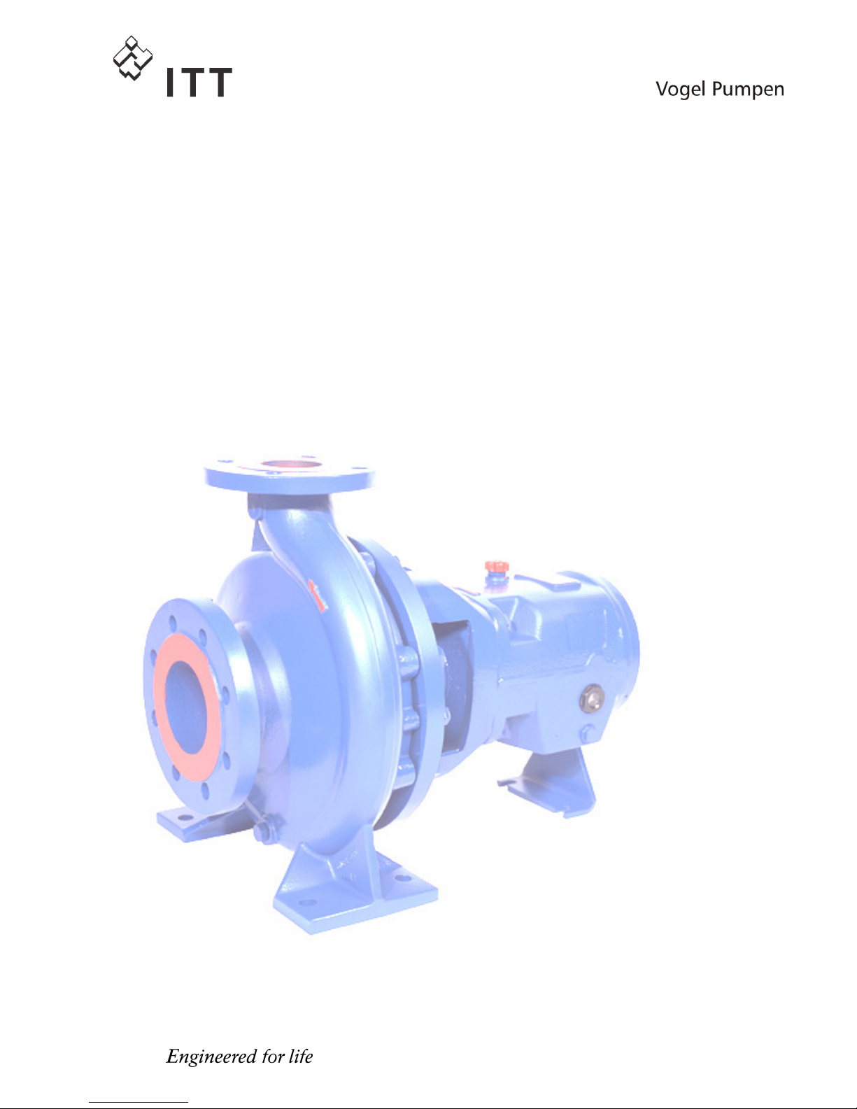
Installation, Operation and
Installation, Operation andInstallation, Operation and
Installation, Operation and
Maintenance Instruction
Maintenance InstructionMaintenance Instruction
Maintenance Instruction
Volute Casing Pumps
Volute Casing PumpsVolute Casing Pumps
Volute Casing Pumps
Model:
Model:Model:
Model:
LSN
LSNLSN
LSN
LSNI
LSNILSNI
LSNI
LSNH
LSNHLSNH
LSNH
LSNIH
LSNIHLSNIH
LSNIH
LSN 100-english
Revision 00
Article No. 4264611 Issue 05/2003
Keep for further
use !
Pay attention to this operating
instruction before the delivery,
installation, start-up a.s.o.!
© ITT VOGEL-Pumpen
Page 2

Page 3
EC-Manufacturers Declaration
(only valid for pump)
acc. to Machine Directive 98/37/EG Appendix II B of European Parliament and Council of 22nd June 1998.
Manufacturer: Pumpenfabrik ERNST VOGEL GmbH
A-2000 Stockerau, Ernst Vogel-Strasse 2
Products: Pumps of model LSN, LSNI, LSNH, LSNIH
The mentioned products are intended
for
Installation into a machine
1)
/ Assembly with other machines1). Their putting
into operation is forbidden so long, till it is proven, that the machine, in which the pump shall be integrated,
corresponds with the regulations of the Machine Directive 98/37/EG.
Used harmonised norms, especially
EN 809
EN ISO 12100 part 1
EN ISO 12100 part 2
Used national technical norms and specifications, especially
DIN 31001
The Declaration of the Manufacturer expires, when the pump is installed into units, where no declaration of
conformity, acc. to the Machine Directive 98/37/EG, is existing.
Stockerau, 22.05.2003
.................. .................................... ................................... .......
Robert Salzbauer
Quality control
1)
Strike out what´s not the case
EC-Declaration of Conformity on customer buyouts
If essential components of the unit (e.g. motors) are provided by the customer and only the assembly of
these components is made by Vogel, the whole conformity must be proved by the customer!
Page 4
EC- Declaration of Conformity
(only valid for units completely delivered by Vogel)
acc. to Machine Directive 98/37/EG Appendix II A of European Parliament and Council of 22nd June 1998.
Manufacturer: Pumpenfabrik ERNST VOGEL GmbH
A-2000 Stockerau, Ernst Vogel-Strasse 2
Products: Pumps of model LSN, LSNI, LSNH, LSNIH
The mentioned products correspond with the regulations of the EC-Machine Directive 98/37/EG.
Used harmonised norms, especially
EN 809
EN ISO 12100 part 1
EN ISO 12100 part 2
EN 60204 part 1
Used national technical norms and specifications, especially
DIN 31001
For Declaration of Conformity of appliances and / or components (e.g. motors) used with the unit, refer to
attachments. The Declaration of Conformity expires, when the pump is installed into units, where no Declaration of
Conformity, acc. to Machine Directive 98/37/EG, is existing.
Stockerau, 22.05.2003
.................. .................................... ................................... .......
Robert Salzbauer
Quality control
EC-Declaration of Conformity
acc. to Directive 94/9/EG (Atex) of European Parliament and Council of 23rd March 1994.
Manufacturer: Pumpenfabrik ERNST VOGEL GmbH
A-2000 Stockerau, Ernst Vogel-Strasse 2
Products: Pumps of model LSN, LSNI, LSNH, LSNIH
are seen as appliances acc to Article 4 Paragraph 1.
The mentioned products are suitable for designated use as appliances of Appliance Group II, Appliance Catagory 2,
explosive atmosphere by gases, vapors or mist, Ignition Protection Class "c", temperature class theoretically available
T1-T., whereby the temperature class T. is specified on the ATEX-plate and the maximum working temperature of the
pumped liquid is shown on the type plate.
The Conformity acc. to Guideline 94/9/EG is only given on designated use - operating data corresponding to the
information on data sheet and / or order confirmation.
Norms which must completely or partly be used regarding the Directive 94/9/EG "Appliances and Protection
Systems for designated use in areas endangered to explosion":
EN 1127-1, Explosive Atmospheres - Explosion protection
- Teil 1: Basis and Methodics.
EN 13463-1, Non-electric appliances for application in areas endangered to explosion
- Teil 1: Basis and Requirements.
prEN 13463-5, Non-electric appliances for application in areas endangered to explosion
- Teil 1: Constructive Safety (c).
For Declaration of Conformity of appliances and / or components (e.g. motors) used with the unit, refer to
attachments. The Declaration of Conformity expires , when the pump is installed into units, where no Declaration of
Conformity, acc. to Directive 94/9/EG and 98/37/EG (Machine Directive), is existing.
The technical documents acc. Appendix VIII of Directive 94/9/EG were handed over to the TÜV Österreich Prüfzentrum Wien, Deutschstraße 10, 1230 Wien.
Stockerau, 12.12.2003
.................. .................................... ................................... .......
Robert Salzbauer
Quality control
Page 5

Pumpenfabrik ERNST VOGEL GmbH
Ernst Vogel-Straße 2 E-Mail: [email protected]
A-2000 Stockerau Internet: www.vogel-pumpen.com
Telefon: (+43) 2266 / 604
Fax: (+43) 2266 / 65311
Page 6

Page 7

Installation, Operating and Maintenance Instruction
Model LSN
LSN 100-english page 1
Revision 00
Article No 4264611
Issue 05/2003
TABLE of CONTENTS
Pump Name Plate ..................................................... 2
ATEX-Label (only for pumps in compliance with
EC directive 94/9/EG)................................................ 2
1. General................................................................... 3
1.1 Guarantee ......................................................... 3
2. Safety Regulations ............................................... 3
2.1 Marking of References in the Operating
Instructions.............................................................. 3
2.2 Dangers of non-observance of the Safety
Instructions.............................................................. 4
2.3 Safety Instructions for the Operator / Worker ...4
2.4 Safety Instructions for Maintenance, Inspections
and Mounting Work ................................................. 4
2.5 Unauthorized Alteration and Spare Parts
Production ............................................................... 4
2.6 Undue Operation............................................... 4
2.7 Explosion Protection.......................................... 4
2.8 Use acc. to Regulations .................................... 6
3. Description ............................................................ 6
3.1 Design ............................................................... 6
3.2 Shaft Sealing..................................................... 7
3.3 Bearings ............................................................ 7
3.4 Approximate Value for Sound Pressure Level .. 7
3.5 Permitted Nozzle Loads and Torques at the
Pump Nozzles ... ..................................................... 7
4. Transport, Handling, Storage .............................. 8
4.1 Transport, Handling........................................... 8
4.2 Storage / Conservation...................................... 9
5. Mounting / Installation ......................................... 9
5.1 Mounting of Pump / Unit.................................... 9
5.2 Connection of Pipings to the Pump................... 9
5.3 Coupling...........................................................10
5.4 Drive ................................................................11
5.5 Electric Connection..........................................12
5.6 Final Control ....................................................12
6. Start-up, Operation, Shut down .........................12
6.1 Initial start-up ...................................................12
6.2 Switch on drive ................................................12
6.3 Restarting ........................................................12
6.4 Limits of Operation ..........................................13
6.5 Lubrication of Bearings....................................13
6.6 Monitoring........................................................14
6.7 Shutting down..................................................14
6.8 Storage / longer periods of non-operation.......14
7. Servicing, Maintenance ......................................14
7.1 General remarks..............................................14
7.2 Mechanical seals .............................................14
7.3 Stuffing boxes..................................................15
7.4 Lubrication and Change of Lubricant...............15
7.5 Coupling...........................................................15
7.6 Cleaning of pump ............................................16
8. Dismantling and repair of pump ........................16
8.1 General remarks..............................................16
8.2 General............................................................16
8.3 Disassembly of Back Pull Out Assembly.........16
8.4 Removal of Impeller.........................................17
8.5 Removal of Shaft Sealing ................................17
8.6 Removal of Bearing .........................................17
8.7 Reconditioning.................................................17
8.8 Mounting..........................................................18
9. Recommended Spare Parts, Spare Pumps ......19
9.1 Spare Parts......................................................19
9.2 Stand-by pumps...............................................19
10. Faults - Causes and Solutions.........................19
Page 8
Installation, Operating and Maintenance Instruction
Model LSN
LSN 100-english page 2
Revision 00
Article No 4264611
Issue 05/2003
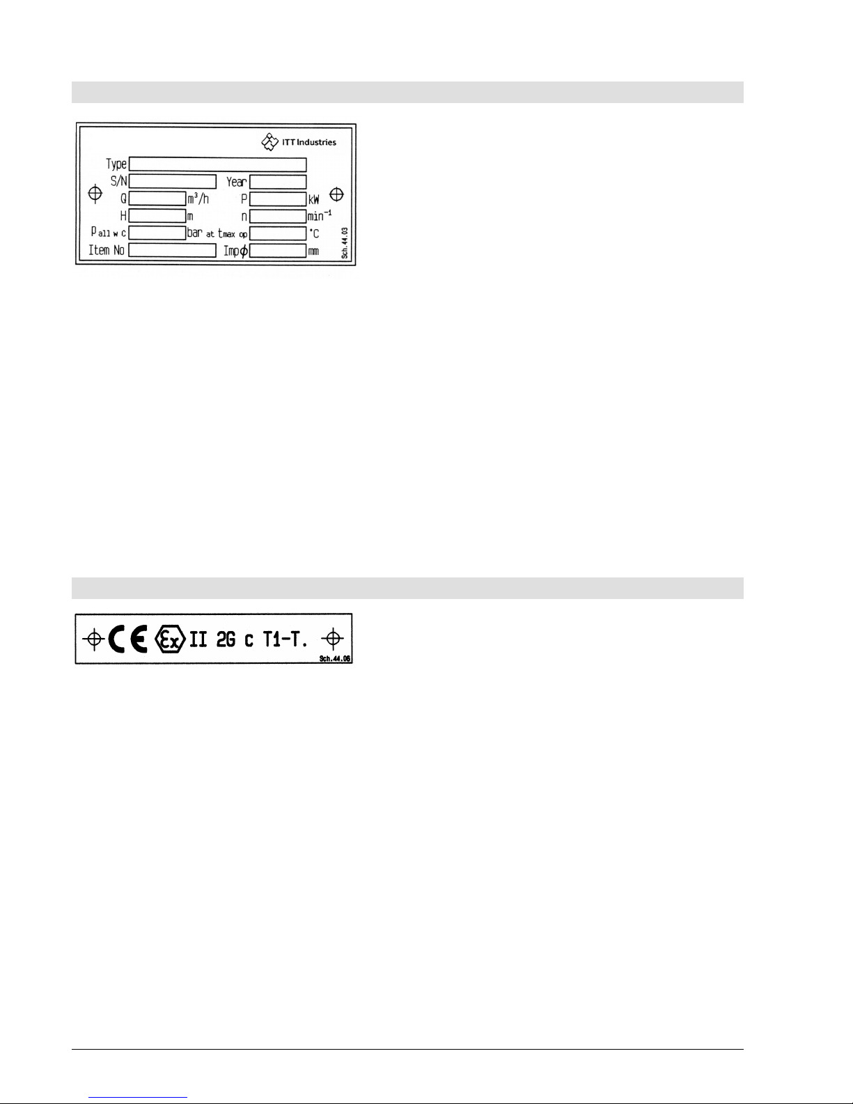
Pump Name Plate
Type *) Type of pump
S/N *) Serial number
Year Year of construction
Q Rated capacity at the operating point
P Rated power at the operating point
H Head (Energy head) at the operating point
n Speed
p
all w C
Max. permitted casing-operation-pressure
(=highest discharge pressure at the rated
operating temperature to which the pump
casing can be used).
t
max op
Maximum permitted operating temperature of
pumped liquid
Item No Customer related order number
Imp∅ Outer diameter of the impeller
*) All details of design and materials are defined with
this information. They must be stated on all inquiries to
the manufacturer resp. orders of spare.
ATEX-Label (only for pumps in compliance with EC directive 94/9/EG)
CE Marking of compliance with the EC directive
94/9/EG
Ex specific marking for explosion protection
II Symbol for the appliance group
2G Symbol for the category (2), explosive
atmosphere due to gases, vapors or mist (G)
c Symbol for used ignition protection
(constructual safety "c")
T1-T. Symbol for classification of the theoretically
available range of the temperature classes -
data for temperature class refer to chapter
2.7.5; Data for maximum permitted
temperature of pumped liquid refer to pump
name plate, data sheet and / or order
confirmation.
The conformity with the EC directive 94/9/EG
"Appliances and Protection Systems for designated
use in areas endangered to explosion" is declared by
the issue of the EC-Declaration of Conformity and the
attachment of the ATEX-label at the pump (bearing
bracket). The ATEX-label is attached additionally to
the pump name plate.
Page 9
Installation, Operating and Maintenance Instruction
Model LSN
LSN 100-english page 3
Revision 00
Article No 4264611
Issue 05/2003
1. General
This product corresponds with the requirements of the
Machine directive 98/37/EG (former 89/392/EWG).
The staff employed on installation, operation,
inspection and maintenance must be able to
prove that they kno
w about the relevant
acci
dent prevention regulations and that they
are suitably qualified for this work. If the staff
does not have the relevant knowledge, they
should be provided with suitable instruction.
The operation safety of the delivered pump resp. unit
(= pump with motor) can only be guaranteed on
designated use according to the attached data sheet
and / or order confirmation resp. chapter 6 "Start-up,
Operation, Shut down".
The operator is responsible for following the
instructions and complying with the safety
requirements given in these Operating Instructions.
Smooth operation of the pump or pump unit can only
be achieved if installation and maintenance are carried
out carefully in accordance with the rules generally
applied in the field of engineering and electrical
engineering.
If not all the information can be found in these
Operating Instructions, please contact us.
The manufacturer takes no responsibility for the pump
or pump unit if the Operating Instructions are not
followed.
These Operating Instructions should be kept in a safe
place for future use.
If this pump or pump unit is handed on to any third
party, it is essential that these Operating Instructions
and the operating conditions and working limits given
in the Confirmation of Order are also passed on in full.
These Operating Instructions do not take into account
all design details and variants nor all the possible
chance occurrences and events which might happen
during installation, operation and maintenance.
We retain all copyright in these Operating Instructions;
they are intended only for personal use by the owner
of the pump or the pump unit. The Operating
Instructions contain technical instructions and
drawings which may not, as a whole or in part, be
reproduced, distributed or used in any unauthorised
way for competitive purposes or passed on to others.
1.1 Guarantee
The guarantee is given in accordance with our
Conditions of Delivery and/or the confirmation of
order.
Repair work during the guarantee period may only be
carried out by us, or subject to our written approval.
Otherwise the guarantee ceases to apply.
Longer-term guarantees basically only cover correct
handling and use of the specified material. The
guarantee shall not cover natural wear and tear and all
parts subject to wear, such as impellers, shaft
sealings, shafts, shaft sleeves, bearings, wear rings
etc. or damage caused by transport or improper
handling.
In order for the guarantee to apply, it is essential that
the pump or pump unit is used in accordance with the
operating conditions given on the name plate,
confirmation of order and in the data sheet. This
applies particularly for the endurance of the materials
and smooth running of the pump and shaft sealing.
If one or more aspects of the actual operating
conditions are different, we should be asked to
confirm in writing that the pump is suitable.
2. Safety Regulations
These Operating Instructions contain important
instructions which must be followed when the pump is
assembled and commissioned and during operating
and maintenance. For this reason, these Operating
Instructions must be read by the skilled staff
responsible and/or by the operator of the plant before
it is installed and commissioned, and they must be left
permanently available at the place where the pump or
pump unit is in use.
These Operating Instructions do not refer to the
General Regulations on Accident Prevention or
local safety and/or operating regulations. The
operator is responsible for complying with these
(if necessary by calling in additional installation
staff).
Equally, instructions and safety devices regarding
handling and disposal of the pumped media and/or
auxilliary media for flushing, lubrication a.s.o.,
especially if they are explosive, toxical, hot a.s.o., are
not part of this operating instruction.
For the competent and prescribed handling only the
operator is responsible.
2.1 Marking of References in the
Operating Instructions
The safety regulations contained in these Operating
Instructions are specially marked with safety signs
acc. to nach DIN 4844:
Safety reference!
Non-
observance can impair the pump and its
function.
EC-Ex Marking
Products intended for use in explosive
atmospheres must be marked.
General Symbol for Danger!
Persons can be endangered.
Warning of electric voltage!
Page 10
Installation, Operating and Maintenance Instruction
Model LSN
LSN 100-english page 4
Revision 00
Article No 4264611
Issue 05/2003
Safety instructions attached directly to the pump resp.
unit must be followed under any circumstances.
Further they must be kept in good readable condition.
In the same way, as these Operating Instructions
of the pump, all possibly attached Operating
Instructions of accessories (e.g. motor) must be
noticed and kept available.
2.2 Dangers of non-observance of the
Safety Instructions
Non-observance of the Safety Instructions can
lead to loss of any claim for damages.
Further, non-observance can lead to following risks:
Failure of important functions of the machine or
facility.
Failure of electronic appliances and measuring
instruments by magnetic fields.
Endangering of persons and their personal
property by magnetic fields.
Endangering of persons by electric, mechanic and
chemical influences.
Endangering of environment through leakage of
dangerous substances.
On application of the unit in areas endangered
to explosion special attention must be paid to
sections marked with Ex.
2.3 Safety Instructions for the Operator /
Worker
Depending on the operating conditions, wear and
tear, corrosion or age will limit the working life of
the pump/pump unit, and its specified
characteristics. The operator must ensure that
regular inspection and maintenance are carried
out so that all parts are replaced in good time,
which would otherwise endanger the safe
operation of the system. If abnormal operation or
any damage are observed, the pump must cease
operation immediately.
If the breakdown or failure of any system or unit
could lead to people being hurt or property being
damaged, such system or unit must be provided
with alarm devices and/or spare modules, and
they should be tested regularly to ensure that they
function properly.
If there is any risk of injury from hot or cold
machine parts, these parts must be protected
against contact by the user, or suitable warning
signs must be affixed.
Contact protection on moving parts (e.g. coupling
guards) must not be removed from systems that
are in operation.
If the sound level of a pump or pump unit is above
85 dB(A) an ear protection has to be used when
staying near the pump for some time.
If dangerous media (e.g. explosive, toxic, hot) leak
out (e.g. from shaft seals), these must be directed
away so that there is no danger to people or the
environment. The provisions of the law must be
observed.
Measures should be taken to exclude any danger
from electricity (e.g. by complying with the local
regulations on electrical equipment). If work is
carried out on live electrical components, they
should be unplugged from the mains or the main
switch turned off and fuse unscrewed. A motor
protection switch is to be provided.
2.4 Safety Instructions for Maintenance,
Inspections and Mounting Work
The operator is responsible that any maintenance,
inspections and mounting work is made by
authorized competent personnel, which must be
informed by havingng read the Operating
Instructions.
Basically, all work on the pump or pump unit
should only be carried out when the pump is
stationary and not under pressure. All parts must
be allowed to return to ambient temperature.
Make sure that no-one can start the motor during
such work. It is essential that the procedure for
stopping the system described in the Operating
Instructions is observed. Pumps or pump systems
that carry media that are dangerous to health must
be decontaminated before being taken apart.
Safety Data Sheets for the various liquids handled.
Immediately after finishing work, all safety and
protective devices must be replaced or restarted.
2.5 Unauthorized Alteration and Spare
Parts Production
Alteration or changes of the machine are permitted
after agreement with the manufacturer.
Original spare parts and accessory authorized by the
manufacturer are serving the safety.
The use of other parts can lead to loss of liability for
therefrom resulting consequences.
2.6 Undue Operation
The operating safety of the delivered machine can
only be guaranteed by designated use acc. to the
following chapters of the Operating Instructions. The
limits stated in the data sheet and / or order
confirmation must not be exceeded under any
circumstances.
2.7 Explosion Protection
On application of units in areas endangered to
explosion measures and references in the chapters
2.7.1 to 2.7.6 must be observed, so that explosion
protection is guaranteed.
2.7.1 Filling of unit
During operation of the pump the system of the
suction and pressure pipe and the pump itself
must permanently be filled with the pumped
liquid. Thus, no explosive atmo
sphere can
develop and the danger of dry-run is avoided.
Page 11
Installation, Operating and Maintenance Instruction
Model LSN
LSN 100-english page 5
Revision 00
Article No 4264611
Issue 05/2003
If the operator can´t guarantee that, according
monitoring measures must be provided.
Equally all seal casings, auxiliary systems of the
shaft sealing, as well as heating and cooling
systems must be filled carefully.
2.7.2 Marking
The marking of the pump refers to the pump
itself. For coupling and motor resp. further
addi
tions a separate Declaration of Conformity,
as well as a corresponding marking must be
available.
Example of of marking at pump:
CE Ex II 2 G c T... .
The marking shows the theoretically applicable range
of temperature classes. The different temperatures,
permitted acc. to pump design, result as shown in
chapter 2.7.5. The same is valid for the drive.
For a whole unit (pump, coupling, motor) with different
temperature classes the lowest is valid.
2.7.3 Rotation Control
Carry out rotation control with speparated
cou
pling halves only! Refer to chapter 5.5 and
6.1 as well.
If danger of explosion is also existing dur
ing
installation, the rotation control must not be
carried out by short start-
up of the empty pump,
to avoid undue temperature increase in case of
contact of rotating and stationary parts.
2.7.4 Operation of pump
The pump must only be started up with fully opened
suction side and slightly opened pressure side valve.
The start-up against closed non-return valve, however,
is possible. Immediately after the start-up the
discharge side valve must be adjusted to the operating
point.
Refer to chapter 6.2, as well.
Operation with closed valve in suction and / or
discharge pipe is not permitted!
There´s a danger, that high surface
tempera
tures are developing at the pump
casing after relatively short time, through fast
heating of the liquid inside the pump.
Fast pressure increase inside the pump can
lead to overload and, thus, the pump can burst.
In chapter 6.4.1 the minimum flow is stated. Longer
operating phases with these flows and the named
liquids don´t cause additional increase of surface
temperature at the pump.
Furthermore the references in chapter 6 of these
operating Instructions must be taken into
consideration.
On pumps with mech. seals the permitted
temperature limits can be exceeded due to dryrun. Dry run not only can occur on insufficien
tly
filled seal casing, but also because of too much
gas in the medium.
Operation of the pump out of the permitted
operating range can lead to dry-run, as well.
2.7.5 Temperature Limits
Under normal operating conditions the highest
temperatures mus
t be expected at the surface
of the pump casing and in the area of the
bearings.
The surface temperature occurring at pump casing
corresponds with the temperature of the pumped
liquid.
If the pump is heated (e. g. heating jacket), care
must be taken,
that the temperature classes,
prescribed for the plant are observed.
In the area of the bearing bracket free contact from
surface to surrounding must be given.
During operation of the pump it must be
se
cured that an overabundant sedimentation of
dust
is avoided (regular cleaning), to prevent
heating of pump surface over the permitted
temperature.
The operator of the plant must secure that the
defined operating temperature is observed. The
max. allowed temperature of the pumped liquid at
suction depends on the particular temperature
class.
The following table shows the theoretical temperature
limits of the pumped liquid in consideration of the
temperature classes acc. to EN 13463-1.
Temperature class acc.
EN 13463-1
Temperature limit of
pumped liquid
T4 (135°C) 135°C
T3 (200°C) 180°C
T2 (300°C) 180°C
T1 (450°C) 180°C
The particular allowed operating temperature of
the pump is shown in the data sheet and / or the
order confirmation resp. the type plate at the
pump.
In the area of the bearings the temperature class T4 is
guaranteed, provided that the ambient temperature is
40°C and the appliance is duly operated and
maintained.
2.7.6 Maintenance
For a secure and reliable operation it must be
secured by regular inspections, that the unit
is
maintained competently and is kept in good
technical condition.
Page 12
Installation, Operating and Maintenance Instruction
Model LSN
LSN 100-english page 6
Revision 00
Article No 4264611
Issue 05/2003
Example: Function of bearings. Operation and
application conditions are essentially responsible for
their achievable life cycle.
By regular control of the lubricant and the running
sound the danger of occurring over temperatures by
bearings running hot or defect bearing seals is
avoided. Refer to chapter 6.6 and 7.4.
The function of the shaft sealing must be secured by
regular control.
If auxiliary systems (e.g. external flushing, cooling,
heating) are installiert, it must be checked, if
monitoring devices are necessary to secure the
function.
2.7.7 Electric switches and control device,
Instrumentation and accessories
Electric switches and control devices,
instrumentation and accessor
ies like e.g. flush
tanks, a.s.o., must correspond with the valid
safety requirements and regulations for
explosion protection.
2.8 Use acc. to Regulations
2.8.1 Speed, Pressure, Temperature
Suitable safety measures must be taken at the
plant to ensu
re that the speed, pressure and
temperature of the pump and the shaft sealing
do not exceed the limit values given in the data
sheet and / or order confirmation. The given
admission pressures (system pressures) must
also be sufficiently high.
Further, pressure shocks, as can occur on too fast
shut down of the facility, must be kept away from the
pump (e.g. by non-return valve at pressure side, fly
wheel, airtanks). Quick temperature changes must be
avoided. They could cause a temperature shock and
lead to damage or impair the function of single
components.
2.8.2 Permitted Nozzle Loads and Torques
Basically the suction and discharge piping must
be designed in such way, that as little forces as
possible are effective to the pump. If that is not
possible,
the values shown in chapter 3.5 must
not be exceeded under any circumstances. This
is valid for the operation as well as for the
standstill of the pump and therefore for all
pos
sible pressures and temperatures of the
unit.
2.8.3 NPSH
The pumped liquid
must have a min. pressure
NPSH at the impeller inlet, so that cavitation
free work is secured resp. a "break off" of the
pump flow is prevented. This condition is
fulfilled, when NPSH-
value of the system
(NPSHA) lies above NPSH-
value of the pump
(NPSHR) under all operating conditions.
Attentention must especially be piad to the NPSHvalue on pumping liquids near the vapour pressure. If
the NPSH-value of the pump remains under, this can
lead from damage of the material due to cavitation to
destruction by overheating.
The NPSH-value of the pump (NPSHR) is shown in
the curves of every pump type.
2.8.4 Sealing, Flushing, Cooling
Suitable provisions for the regulation and monitoring of
sealing, flushing or cooling are to be provided.
When handling dangerous liquids or if temperatures
are high, care should be taken to ensure that the
pump ceases operating if the sealing, flushing or
cooling system fails.
Sealing, flushing and cooling systems must always be
operational before the pump is started up. They
should not be taken out of operation until the pump
has stopped, provided that the nature of the operation
allows this at all.
2.8.5 Back Flow
In systems where pumps are operating in closed
circuits under pressure (gas cushions, steam
pressure), the pressure of the gas cushion must not
be reduced via the pump, since the back flow speed
may be much higher than the operating speed, which
would destroy the unit.
3. Description
3.1 Design
LSN-pumps are single-stage volute casing pumps in
process design. Hydraulic design and dimensions
comply with ISO 2858/ EN 22858, the technical design
complies with ISO 5199/EN 25199.
LSNI-pumps as design LSN, except that they have an
inducer.
LSNH- and LSNIH-pumps pumps additionally
possess a cooling or heating of the casing cover
and/or the volute casing.
Page 13
Installation, Operating and Maintenance Instruction
Model LSN
LSN 100-english page 7
Revision 00
Article No 4264611
Issue 05/2003
The pumps are designed as modular systems and
can, therefore, be delivered in many variants (e.g.
different materials, shaft sealings, different kinds of
lubrication, cooling / heating, a.s.o.).
The permitted application conditions and design
details of the delivered pump are shown in the
attached data sheet and / or order confirmation.
3.2 Shaft Sealing
Basically there are two kinds of shaft sealing: the
paccking and the mechanical seal, whereas, there
again are many variants of both kinds. At the data
sheet and / or the order confirmation the shaft sealing
type of your pump is shown.
An instruction for the packing of a stuffing box resp.
for the mounting and operation of mech. seals can be
found in the appendix of the particular "Mounting
Instructions of the Shaft Sealing".
Further details about packings and mech. seals,
as well as the therewith connected accidental
dangers, you can find in chapter 6.6 and in
chapters 7.2 and 7.3.
In areas endangered to explosion t
he use of
pumps with packings is forbidden!
3.3 Bearings
The pump shaft is guided by antifriction bearings. In
the data sheet and / or order confirmation you can
see, if your pump is designed for oil lubrication
(standard design) or grease lubrication (special
design).
In areas endangered to explosion the use of
pumps with grease lubricated bearings is
forbidden!
3.3.1 Used bearings
The size of the bearing bracket of your pump is shown
in the data sheet and / or order confirmation.
Bearing type
Bearing bracket
pump side drive side
24 6307 - C3 3307A - C3
32 6309 - C3 3309A - C3
42 6311 - C3 3311A - C3
48 6313 - C3 3313A - C3
3.3.2 Oil Sump Cooling
On temperatures of the pumped liquid over 160°C an
oil sump cooling is required.
For connection refer to list "Connections" in the annex.
For cooling use pure, non-aggressive water with a
maximum incomming temperature of 30°C.
Cooling water should be hand-warm at discharge.
The pressure in the cooling system must not
exceed max. 6 bar.
Provide control devices for temperature and
pressure monitoring.
3.4 Approximate Value for Sound
Pressure Level
Sound pressure level LpA in dB(A)
Pump alone Pump + Motor
Nominal
power
PN
in kW
2950
min-1
1450
min-1
975
min-1
2950
min-1
1450
min-1
975
min-1
0,55 50,5 49,5 49,0 58,0 52,0 51,5
0,75 52,0 51,0 50,5 59,0 54,0 53,0
1,1 54,0 53,0 52,5 60,0 55,5 54,5
1,5 55,5 55,0 54,5 63,5 57,0 56,0
2,2 58,0 57,0 56,5 64,5 59,0 58,5
3,0 59,5 58,5 58,0 68,5 61,0 62,0
4,0 61,0 60,0 59,5 69,0 63,0 63,0
5,5 63,0 62,0 61,5 70,0 65,0 65,0
7,5 64,5 63,5 63,0 70,5 67,0 67,0
11,0 66,5 65,5 65,0 72,0 69,0 68,5
15,0 68,0 67,0 66,5 72,5 70,0 70,5
18,5 69,0 68,5 68,0 73,0 70,5 74,0
22,0 70,5 69,5 69,0 74,5 71,0 74,0
30,0 72,0 71,0 70,5 75,0 72,0 73,0
37,0 73,0 72,0 71,5 76,0 73,5 73,5
45,0 74,0 73,0 72,5 77,0 74,5 73,5
55,0 75,5 74,5 74,0 78,0 75,5 75,0
75,0 77,0 76,0 75,5 80,0 76,5 76,0
90,0 78,0 77,0 -- 80,5 77,5 --
110,0 79,0 78,0 -- 82,5 78,5 -132,0 80,0 79,0 -- 83,0 79,5 -160,0 81,0 80,0 -- 83,5 80,5 --
Sound pressure level LpA measured in 1 m distance
from pump surface acc. to DIN 45635, part 1 and 24.
Room and foundation influences are not considered.
The tolerance for these values is ±3 dB(A).
Addition with 60 Hz-operation:
Pump alone: −
Pump with motor: +4 dB(A)
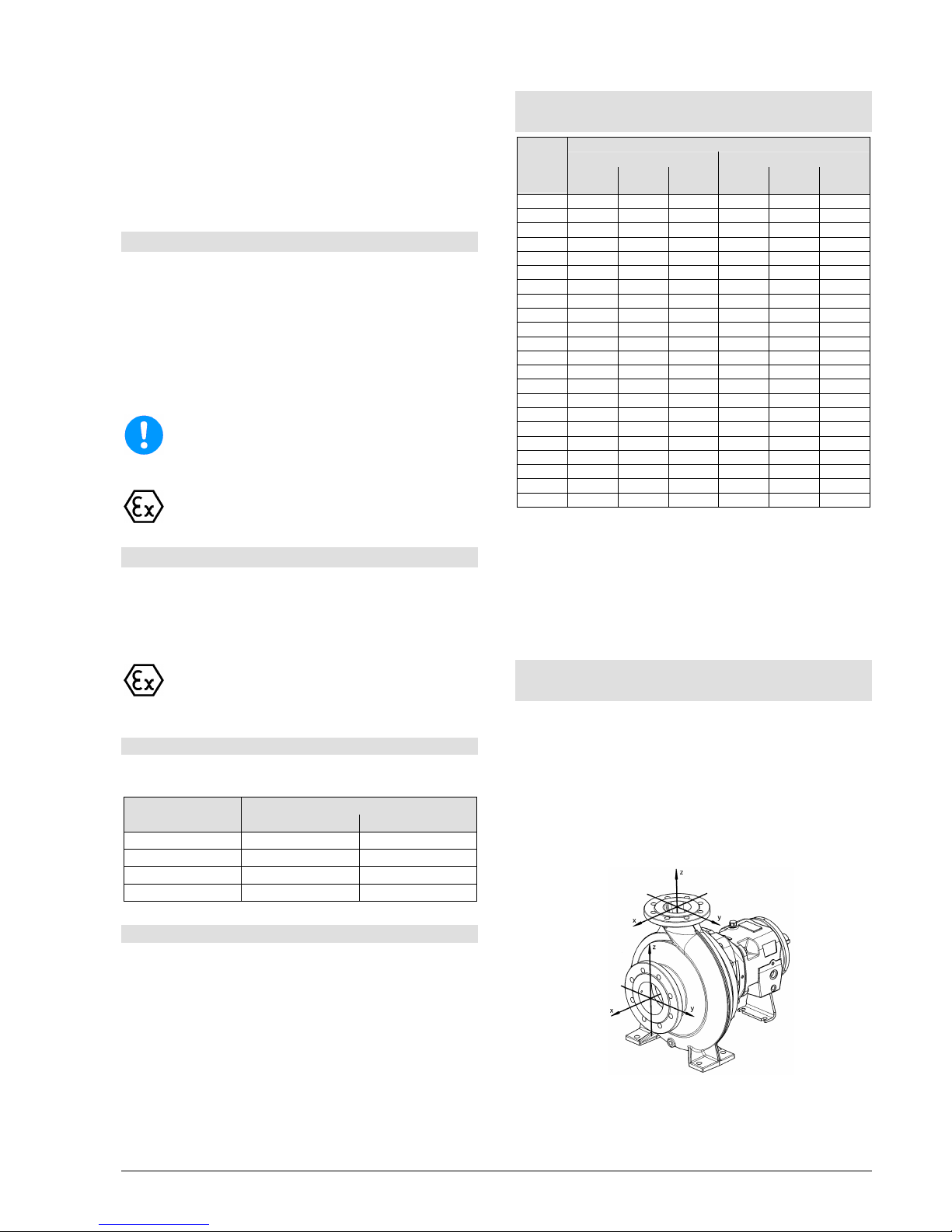
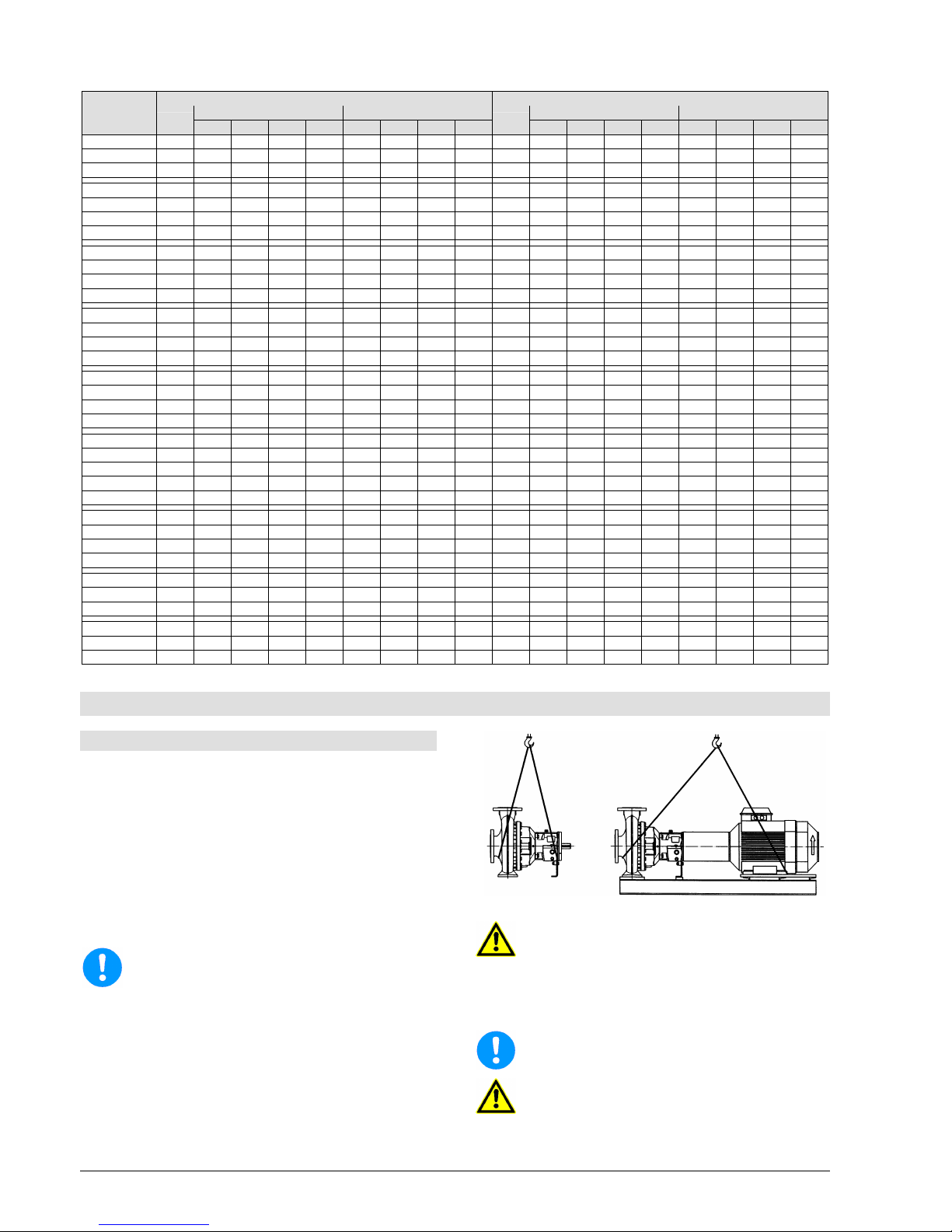
3.5 Permitted Nozzle Loads and Torques
at the Pump Nozzles ...
... following the Europump-Recommendation for
pump acc. to ISO 5199.
The data for forces and torques are only valid for static
piping loads.
The values given in the chart are valid for pump units
with standard-LSN-base frames (ungrouted).
All values for forces and torques refer to standard
materials EN-GJS400-18LT and 1.4408.
pic 1
Page 14
Installation, Operating and Maintenance Instruction
Model LSN
LSN 100-english page 8
Revision 00
Article No 4264611
Issue 05/2003
Suction nozzle Discharge nozzle
Forces in N Torques in Nm Forces in N Torques in Nm Sizes
∅DN
Fx Fy Fz
∑F
Mx My Mz
∑M
∅DN
Fx Fy Fz
∑F
Mx My Mz
∑M
40-25-160 40 880 770 700 1370 900 630 740 1330 25 530 490 600 920 630 420 490 920
40-25-200 40 880 770 700 1370 900 630 740 1330 25 530 490 600 920 630 420 490 920
40-25-250 40 880 770 700 1370 900 630 740 1330 25 530 490 600 920 630 420 490 920
50-32-160 50 1150 1050 950 1820 980 700 800 1450 32 630 600 740 1160 770 530 600 1120
50-32-200 50 1150 1050 950 1820 980 700 800 1450 32 630 600 740 1160 770 530 600 1120
50-32-250 50 1150 1050 950 1820 980 700 800 1450 32 630 600 740 1160 770 530 600 1120
50-32-315 50 1150 1050 950 1820 980 700 800 1450 32 630 600 740 1160 770 530 600 1120
65-40-160 65 1470 1300 1200 2300 1050 770 840 1550 40 770 700 880 1370 900 630 740 1330
65-40-200 65 1470 1300 1200 2300 1050 770 840 1550 40 770 700 880 1370 900 630 740 1330
65-40-250 65 1470 1300 1200 2300 1050 770 840 1550 40 770 700 880 1370 900 630 740 1330
65-40-315 65 1470 1300 1200 2300 1050 770 840 1550 40 770 700 880 1370 900 630 740 1330
80-50-160 80 1750 1580 1440 2760 1120 800 910 1650 50 1050 950 1150 1820 980 700 800 1450
80-50-200 80 1750 1580 1440 2760 1120 800 910 1650 50 1050 950 1150 1820 980 700 800 1450
80-50-250 80 1750 1580 1440 2760 1120 800 910 1650 50 1050 950 1150 1820 980 700 800 1450
80-50-315 80 1750 1580 1440 2760 1120 800 910 1650 50 1050 950 1150 1820 980 700 800 1450
100-65-160 100 2350 2100 1900 3670 1230 880 1020 1820 65 1300 1200 1470 2300 1050 770 840 1550
100-65-200 100 2350 2100 1900 3670 1230 880 1020 1820 65 1300 1200 1470 2300 1050 770 840 1550
100-65-250 100 2350 2100 1900 3670 1230 880 1020 1820 65 1300 1200 1470 2300 1050 770 840 1550
100-65-315 100 2350 2100 1900 3670 1230 880 1020 1820 65 1300 1200 1470 2300 1050 770 840 1550
125-80-160 125 2765 2485 2240 4350 1470 1050 1330 2140 80 1580 1440 1750 2760 1120 800 910 1650
125-80-200 125 2765 2485 2240 4350 1470 1050 1330 2140 80 1580 1440 1750 2760 1120 800 910 1650
125-80-250 125 2765 2485 2240 4350 1470 1050 1330 2140 80 1580 1440 1750 2760 1120 800 910 1650
125-80-315 125 2765 2485 2240 4350 1470 1050 1330 2140 80 1580 1440 1750 2760 1120 800 910 1650
125-80-400 125 2765 2485 2240 4350 1470 1050 1330 2140 80 1580 1440 1750 2760 1120 800 910 1650
125-100-200 125 2750 2500 2240 4350 1470 1050 1330 2140 100 2100 1900 2350 3670 1230 880 1020 1820
125-100-250 125 2750 2500 2240 4350 1470 1050 1330 2140 100 2100 1900 2350 3670 1230 880 1020 1820
125-100-315 125 2750 2500 2240 4350 1470 1050 1330 2140 100 2100 1900 2350 3670 1230 880 1020 1820
125-100-400 125 2750 2500 2240 4350 1470 1050 1330 2140 100 2100 1900 2350 3670 1230 880 1020 1820
150-125-250 150 3500 3150 2850 5500 1750 1230 1450 2560 125 2500 2240 2750 4350 1470 1050 1330 2140
150-125-315 150 3500 3150 2850 5500 1750 1230 1450 2560 125 2500 2240 2750 4350 1470 1050 1330 2140
150-125-400 150 3500 3150 2850 5500 1750 1230 1450 2560 125 2500 2240 2750 4350 1470 1050 1330 2140
200-150-250 200 4700 4200 3780 7350 2280 1610 1850 3350 150 3150 2850 3500 5500 1750 1230 1450 2560
200-150-315 200 4700 4200 3780 7350 2280 1610 1850 3350 150 3150 2850 3500 5500 1750 1230 1450 2560
200-150-400 200 4700 4200 3780 7350 2280 1610 1850 3350 150 3150 2850 3500 5500 1750 1230 1450 2560
4. Transport, Handling, Storage
4.1 Transport, Handling
Check the pump / pump unit immediately upon
delivery / receipt of despatch for damage or
missing parts.
The pump / pump unit must be transported
carefully and by competent personnel. Avoid
serious impacts.
Keep the pump/pump unit in the same position in
which it was supplied from the factory. Take note
of the instructions on the packaging.
The suction and discharge side of the pump must
be closed with plugs during transport and storage.
Dispose of all packing materials in accordance
with local regulations.
Lifting devices (e.g. fork-lift truck, crane, crane
device, pulleys, sling ropes, etc.) must be
sufficiently strong and must only be used by
authorized persons. The weight of the pump /
pump unit is given in the data sheet.
The pump / pump unit may only be lifted by solid
points such as the casing, flanges or frame.
Picture 2 shows the correct method of carrying by
crane.
pic 2
Do not stand underneath suspended loads.
Take note of the general regulations on
prevention of accidents.
The pump / pump unit must be secured against
tipping over and slipping until it has been fixed
in its final location.
Sling ropes must not be fixed to ends of shafts
or the ring loops of the motor.
Slipping out of the pump / pump unit of the
trans
port lifting device can cause damages to
persons and things.
Page 15

Installation, Operating and Maintenance Instruction
Model LSN
LSN 100-english page 9
Revision 00
Article No 4264611
Issue 05/2003
4.2 Storage / Conservation
Pumps or units, which are stored over a longer period
before start-up (max. 6 months), must be protected
from moisture, vibrations and dirt (e.g. by wrapping in
oil paper or plastic). Pumps must basically be stored in
a place where they are protected from the weather,
e.g. under dry cover. During this time, all suction and
discharge branches and all other intakes and outlets
must be closed with dummy flanges or plugs.
For longer periods of storage conservation
measurements at machined surfaces and packing with
moisture protection can be necessary!
5. Mounting / Installation
5.1 Mounting of Pump / Unit
5.1.1 Mounting of pump on a base frame
The pump and motor (= pump unit) must be provided
with a base frame made of steel or cast iron or a
fabricated (welded) frame, where this does not exist
already or if it is not included in the delivery. This base
frame must be placed on a foundation which can
withstand all loads that arise during operation (refer to
chapter 5.1.2).
When mounting the pump onto the base frame the
following must to be noticed:
The base frame must be solid, so that there won´t
occur any twists or vibrations during the operation.
The mounting surfaces of the pump feet and
motor on the base frame must be flat (machining
is recommended). Bracing of the pump leads to
premature breakdown of the pump and to a loss of
warranty.
The drillings for the pump mounting must be in
such a way, that safe fastening is guaranteed.
Between pump and motor shaft an adequate
space must be left depending on the used
coupling, refer to chapter 5.3.
Between pump and base frame there must be an
adequate shimming, so that in the case of
replacement of the pump the equal height
between bottom and centerline can be adjusted
(recommended vertical adjustment 4 to 6 mm).
Align pump and motor, refer to chapter 5.3, as
well.
5.1.2. Mounting the unit to a foundation
The place, where the pump is mounted must be
prepared acc. to the dimensions of the dimensional
drawings. The concrete foundations should have
sufficient firmness acc. to DIN 1045 or equal standard
(min. BN 15), to ensure a secure, functional mounting.
The concrete foundation must have set, before the
unit is errected. Ist surface must be horizontal and
even.
Sufficient space must be provided for
maintenance and repair wo
rk, especially for
replacing the drive motor or the complete pump
unit. The motor fan must be able to take in
enough cool air, and the intake grille must
therefore be at least 10 cm away from any wall,
etc.
For the set of anchor bolts according recesses
must be provided. If that is not the case, concrete
expansion bolts resp. epoxy capsle anchor bolts
can be used.
When mounting the pump on the foundation it
must be adjusted at the discharge nozzle by
means of a spirit-level (at discharge nozzle). The
permitted deviation is 0,2 mm/m. After inserting
the foundation bolts they must be cast in the
foundation with concrete. After setting of the grout
the coupling alignment must be checked
according chapter 5.3.1 and possible
misalignments must be corrected by adjusting
foundation frame in the area of the drive motor.
The smoothness of the base frame must be 0,2
mm/m before it is filled up resp. fastened. For
adjustment leveling shims or leveling screws
(optional, not delivered standardwise) can be
used. Levelling shims must be inserted next to the
foundation anchors and must lie plainly. After that
fasten foundation bolts symmetrically but only
slightly. Fill in base frame with non shrinking grout.
Notice:
Avoid air bubbles (e.g. by vibrating).
Check that the grout has properly set and
hardened.
Take care for the after-treatment of the concrete
acc. to DIN 1045.
After setting, tighten the foundation anchor evenly and
firmly. Check alignment of coupling acc. to chapter
5.3.1 and re-adjust, if necessary. Further, check that
all screws between pump / motor and the base frame
fit snugly.
Although the original LSN-base frames are designed
solidly, the filling in of the adjusted base frame up to
the rim is recommended.
If vibrations are transmitted to the foundation from
adjoining components, it must be guarded through
adequate vibration damping paddings (vibrations
from outside can impair the bearing).
To prevent vibrations being transmitted to
adjoining components, the foundation should be
laid on a suitable insulating base.
The size of these insulating pads will vary,
de
pending on circumstances, and should
there
fore be determined by an experienced
specialist.
5.2 Connection of Pipings to the Pump
The pump must not be used as fixed point for
the piping.
The permitted piping loads must not
be exceeded, refer to chapter 3.5.
Page 16
Installation, Operating and Maintenance Instruction
Model LSN
LSN 100-english page 10
Revision 00
Article No 4264611
Issue 05/2003
5.2.1 Suction and discharge pipe
The pipes must be of a size and design that liquid
can flow freely into the pump and that the pump
functions without problems. Particular attention is
to be paid to ensuring that suction pipes are
airtight and that the NPSH values are observed.
Under suction lift condition lay the suction pipe in
the horizontal section towards the pump so that it
is slightly inclined upwards so that no air traps
occur. Under positive suction head condition
install the suction pipe work slightly declined
towards the pump. Do not install fittings or elbows
right before the suction nozzle.
If the suction supply is under vacuum and
entrained gas may be present in the liquid, it is
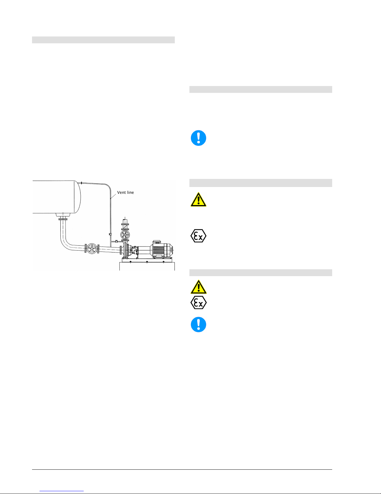
recommended that a vent line be considered
upstream of the pump suction with return to the
suction supply, above the max liquid level.
An additional flushed piping - discharge branch-
vent line - makes it easier to de-aerate the pump
before start-up (pic 3).
pic 3
When laying the pipes, make sure that the pump
is accessible for maintenance, installation and
disassembly.
Notice "Permitted Forces on Flanges" (chapter
3.5).
If expansion joints are used in the pipes, they
have to be supported in such a way that the pump
is not loaded unduely high because of the
pressure in the pipes.
Before connecting up to pump: remove protective
coverings from suction and discharge branches.
Before starting up, the pipe system, fittings and
equipment must be cleaned to remove weld
spatter, scale etc. Any pollutants are to be
completely removed from pump units that are
directly or indirectly connected to drinking water
systems before being installed and taken into use.
To protect the shaft sealing (especially mechanical
seals) against foreign impurities, it is
recommended that a sieve, 800 micron, is
installed in the suction/intake pipe when the motor
is being started up.
If the pipe system is tested with the pump
installed, do not exceed the maximum permitted
casing pressure of the pump and/or shaft sealing
(see data sheet).
When emptying the pipe after the pressure test,
make sure that the pump is treated properly
(danger of rust and problems when starting up).
In the case of pumps with stuffing boxes, replace
packing after pressure test (packing may be overcompressed and thus no longer suitable for use).
5.2.2 Additional connections
Any required sealing, flushing or cooling pipe
connections must be installed. Please consult the data
sheet to see which pipes, pressures and amounts are
necessary. The position and size of connections to the
pump are given in the appendix, "Connections".
These connections are essential for the
function!
It is recommended that a pipeline is installed to take
off any leakage from the shaft seal. For connection,
see appendix, "Connections".
5.3 Coupling
Make sure that nobody can start the motor
during work on the coupling.
According to Accident Prevention Regulations,
the pump unit may only be operated when the
coupling guard is mounted.
On operation in zone 1 and 2 a coupling with
valid Atex-certification must be used.
The Operating Instructions of the manufacturer
must be followed.
5.3.1 Alignment of coupling
The alignment of the coupling must be carried
out with the utmost care and attention, so that
the unit will operate without failure. If you do not
pay attention to this hint you will lose your
warranty!
After mounting onto the foundation and the
connection of the pipings the coupling must be
a
djusted again, even, if the unit was delivered
completely mounted on the frame.
Before starting installation, carefully clean shaft
ends and coupling components.
Before adjusting the coupling unfasten screws
(901.12) between bearing bracket (330) and
casing foot (183) and only fasten again after the
adjustment. Repeat measurement after fastening
of screws (901.12).
The unit is properly aligned, when a ruler, which is
laid axially over both coupling halves, has the
same distance to the particular shaft everywhere
on the circumference. Further, both coupling
halves must have the same distance to one
another on every of the circumference. This must
be checked by means of a tracer, gauge or dial
gage; refer to pic. 4 and 5.
The permitted tolerances for your coupling is
shown in the operating instructions of the
Page 17
Installation, Operating and Maintenance Instruction
Model LSN
LSN 100-english page 11
Revision 00
Article No 4264611
Issue 05/2003
coupling. For the exact characterization of your
coupling refer to data sheet and / or order
confirmation.
pic 4 - Alignment of coupling with gauge and ruler
pic 5 - Alignment of coupling with spacer
Control alignment of coupling again in operation
warm condition and on system pressure (if
available) and correct, if necessary. Pay
atten
tion to chapter 6 beforehand! It must be
possi
ble to turn the unit easily and harmoniously
by hand.
Improper alignment of the unit can lead to
damages at coupling and unit!
Mount coupling guard after alignment and
before start-up.
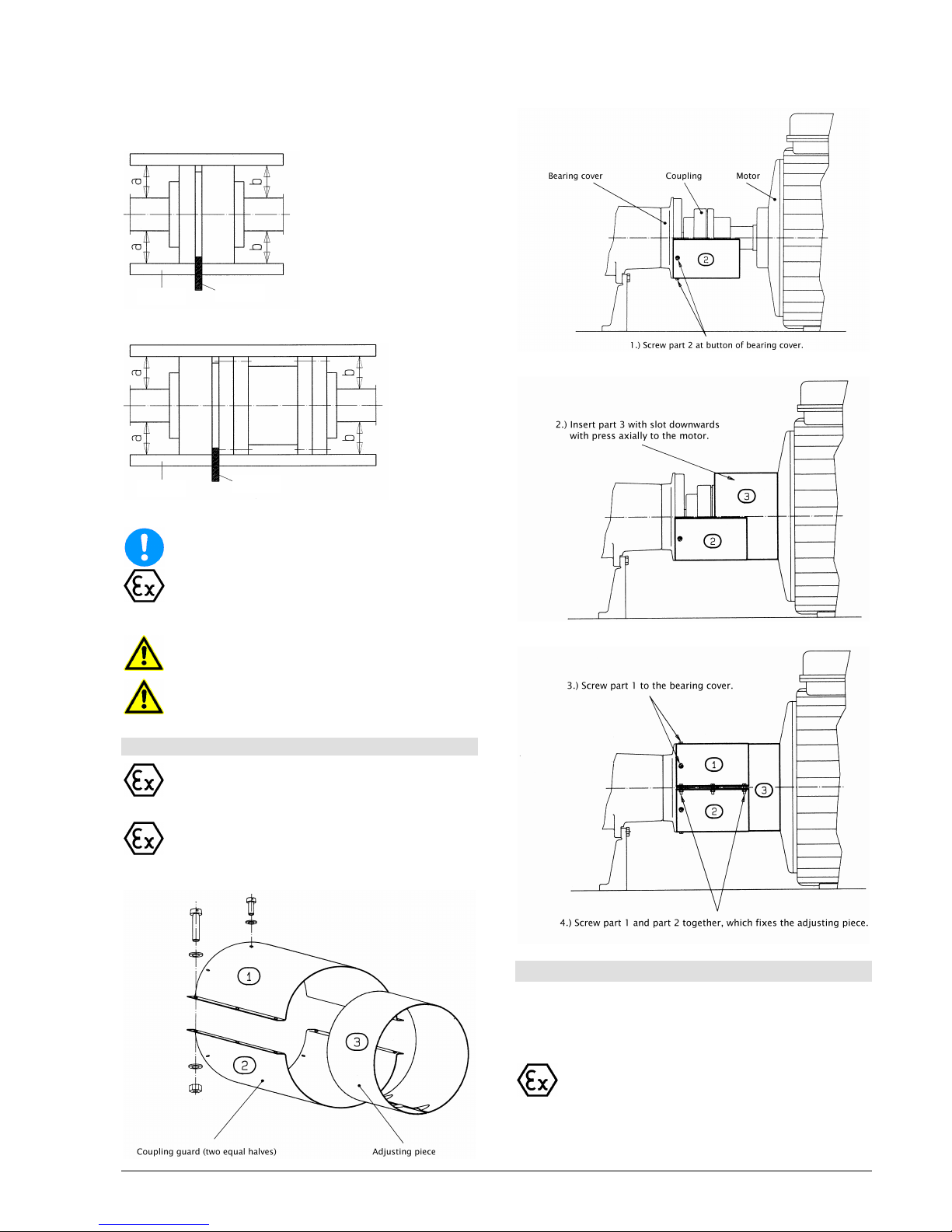
5.3.2 Coupling Guard
Acc. to accident prevention regulations the
pump must only be operated with coupling
guard.
Care has to be taken, that the used coupling
guard consits of non-sparking material.
Parts:
Assembly:
5.4 Drive
On selecting the motor size care has to be taken, that
the requirements acc. to ISO 5199 are fulfilled. Note
the Operating Instructions of the motor
manufacturer.
On application in zone 1 and 2 a motor with
valid Atex-certification must be used.
ruler
gauge
ruler
gauge
Page 18
Installation, Operating and Maintenance Instruction
Model LSN
LSN 100-english page 12
Revision 00
Article No 4264611
Issue 05/2003
5.5 Electric Connection
Electrical connection work may only be carried
out by an authorised professional. The rules
a
nd regulations valid for electrical technology,
especially those concerned with safety
meas
ures, must be observed. The regulations
of the national power supply companies
operating in that area must also be observed.
Before starting work, check that the information on the
motor name plate is the same as the local mains
network. The power supply cable of the coupled drive
motor must be connected up in accordance with the
wiring diagram produced by the motor manufacturer. A
protective motor switch must be provided.
In areas endangered to explosion IEC 60079-
14
must additionally be noticed for the electric
installation.
Care must be taken that the base frame (2x
M10-
thread available for earthing screws) is
earthed by means of corresponding measures.
The direction of rotation must only be checked
when the pump is full. Dry running will cause
damage to the pump.
5.6 Final Control
Check alignment of coupling acc. to chapter 5.3.1
again. It must be possible to turn the unit easily by
hand at the coupling.
6. Start-up, Operation, Shut down
The plant may only be started up by people who
are familiar with the local safety regulations and
with these Operating Instructions (especially
with the safety regulations and safety
instructions given here).
6.1 Initial start-up
Before starting up the pump, check, if the following
points were controlled and carried out:
If pump is oil lubricated, first open oil drain (GD)
and drain off any liquid that may have collected
(e.g. condensation). Close oil drain (GD) and fill oil
as described in chapter 6.5.1.
For pumps with grease lubrication, no further
lubrication is needed before initial start-up.
Pump and suction pipe must be filled completely
with liquid when starting up.
Turn pump unit once again by hand and check
that it moves smoothly and evenly.
Check that coupling guard is installed and that all
safety devices are operational.
Switch on any sealing, flushing or cooling devices
that are provided. See data sheet for quantity and
pressure.
Open valve in suction /intake pipe.
Set discharge side valve to approx. 25% of rated
flow quantity. With pumps with a discharge branch
rated width less than 200, the valve can remain
closed when starting up.
Secure, that unit is electrically connected acc. to
all regulations and with all safety devices.
Check direction of rotation by switching on and off
briefly. It must be the same as the directional
arrow on the bearing frame.
6.2 Switch on drive
Immediately (max. 10 seconds on 50 Hz resp.
max. 7 seconds on 60 Hz currency feed) after
reaching normal operating speed open discharge
valve adjust the required operating point. The
pumping data shown at the type plate resp. in the
data sheet and / or the order confirmation must be
met. Every change is only permitted after talking
with the manufacturer!
Operation with closed valve in the suction and /
or discharge piping is not permitted.
On starting-up without back-pressure, the back-
pressure must be produced through throttling at
the discharge side. After reaching full backpressure open valve
In order that the shaft sealing can be monitored
and maintained unhindered, no protection cover
is provided in this area. Therefore special
atten
tion is required when pump is working (no
long hair, loose clothes, a.s.o.).
Packing:
Packings need leakage for troublefree function
(dropwise outlet of pumped medium). Adjust
ample leakage in the beginning. Reduce that
slowly during the first operating hours by
continuously fastening of gland (see position "452"
and "920.31" in sectional drawing) when pump is
running. Assume 30-100 drops / minute as
approx. value.
Dry running packings harden and destroy the
shaft sealing resp. the shaft.
If pump does not reach attended head or if
atypical sounds or vibrations do occur:
Switch off
pump (see chapter 6.7) and seek for
causes (see chapter 10).
6.3 Restarting
Basically, the same procedure should be followed as
for starting up for the first time. However, there is no
need to check the direction of rotation and the
accessibility of the pump unit.
The pump should only be automatically restarted if it
has been made sure that the pump has remained
filled whilst stand by.
Page 19
Installation, Operating and Maintenance Instruction
Model LSN
LSN 100-english page 13
Revision 00
Article No 4264611
Issue 05/2003
Be particularly careful not to touch hot machine
parts and when working in the unprotected shaft
seal area. Remember
that automatically
con
trolled systems may switch themselves on
suddenly at any time.
Suitable warning signs
should be affixed.
6.4 Limits of Operation
The operating limits of the pump / unit regarding
pressure, temperature, performance and speed
are s
hown in the data sheet and / or order
con
firmation and must be observed under any
circumstances!
Do not exceed the output given on the motor
name plate.
Avoid sudden changes in temperature
(temperature shocks).
The pump and motor should run evenly and
without vibrations; check at least once a week.
6.4.1 Flow min. / max.
If no other data are given in the curves or data sheets,
the following is valid:
Q
min
= 0,1 x Q
BEP
for for short time operation
Q
min
= 0,3 x Q
BEP
for continuous operation
Q
max
= 1,2 x Q
BEP
for continuous operation *)
Q
BEP
= Flow in efficiency optimum
*) on condition that NPSH
facility
> (NPSH
pump
+ 0,5 m)
6.4.2 Abrasive Media
On pumping liquids with abrasive components
an increased wear at hydraulic and shaft sea
ling
must be expected. The intervals of inspec
tion
should be reduced compared to the usual
times.
6.4.3 Permitted number of starts
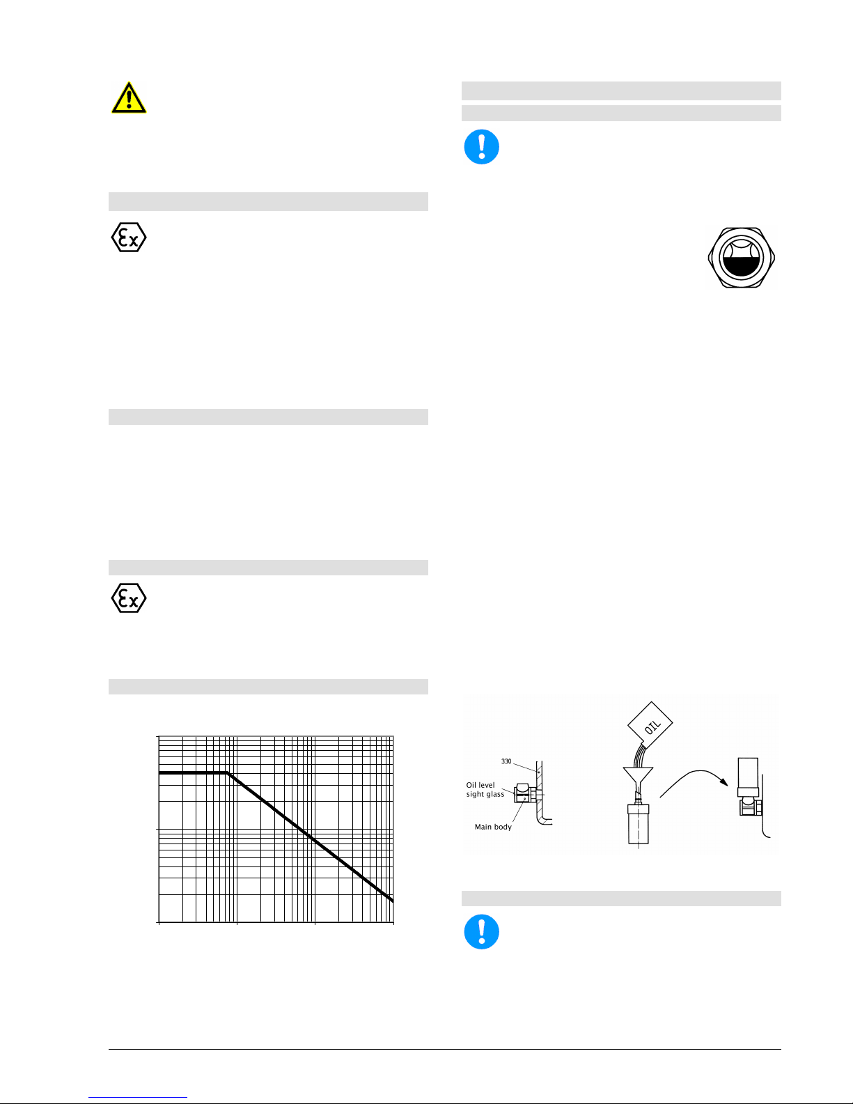
The permitted number of starts of the pump must not
be exceeded, see diagram 6.
1,0
10,0
100,0
1 10 100 1000
Motor power [kW]
max. perm. starts/h
diagram 6
With electric motors, the permitted number of starts is
given in the attached motor operating instructions.
If two different figures are given, the lower figure is
valid.
6.5 Lubrication of Bearings
6.5.1 Oil lubrication
The bearing bracket must be fil
led up with oil.
For quality of oil refer to chapter 7.4.1.
For qantity of oil refer to chapter 7.4.1.
The pumps are delivered without oil filling!
Oil level sight glass (standard design)
Remove oil filling plug (637) and fill oil
into the connection opening (GF1).
Fill in oil up to the middle of the oil level
sight glass (642) (pic 7). Keep level
ex
actly. Overfilling leads to increased
bear
ing temperature and possibly oil
leaka
ge. If oil level is too low this can
cause shortcoming of lubrication.
pic 7
Constant level oiler (special design)
Supplied loose.
Unscrew the reservoir from the main body (right
threaded) and set aside.
Seal the main body into the bearing bracket (330),
through a PTFE sealing tape, at connection for
constant level oiler (638). Tighten until threaded
boss is in vertical position (picture 8).
Remove the oil filling plug (637) (upper side of
bearing bracket) and fill in oil through the
connection opening (GF1), until the oil level
reaches almost the middle of the oil level sight
glass in the main body.
Using a funnel, fill the reservoir (picture 8).
Make sure that o-ring is on reservoir spout.
Place thumb over reservoir spout, invert, and
insert the spout into the internal threaded boss on
the main body. Tighten reservoir (picture 8).
Now the oil is flowing from the reservoir into the
bearing chamber.
Repeat filling till the reservoir stays full to 2/3rd.
Refill oil as soon as the oil level falls below 1/3rd.
pic 8
6.5.2 Grease lubrication
For quality of grease refer to chapter 7.4.2.
For quantity of grease refer to chapter 7.4.2.
The bearings are already filled with lithium based
grease at the factory and are thus ready for use.
The grease provided is suitable for a temperature
range from -30° to +90°C (measured at surface of
bearing bracket).
Page 20
Installation, Operating and Maintenance Instruction
Model LSN
LSN 100-english page 14
Revision 00
Article No 4264611
Issue 05/2003
Re-lubrication via the two grease nipples (636).
Bearing temperature (measured at bearing
bracket) should lie max. 50°C over ambient
temperature and must not exceed 90°C, control
weekly at least. On grease lubrication the bearing
temperature can temporarily be higher by 5-10°C
after regreasing, till a possible surplus of grease in
the bearings is cut.
6.6 Monitoring
In areas endangered to explosion it is
recom
mended to monitor the temperature of the
bearings and the vibration
s of the bearing
bracket.
Regular monitoring and maintenance will ex
tend
the life of your pump or pump system.
Check oil level at least once a week and top up if
necessary.
Check pump for leaks at least once a week.
On packing, check quantity of leakage at least
once a week (see chapter 6.2 section "Packing").
Check the regulating and monitoring devices of
any sealing, flushing or cooling systems once a
week to ensure that they function properly.
Outgoing cooling water should be handwarm.
With double mechanical seals, monitor pressure
and flow rate in mechanical seal area; check at
least once a week.
Pumps which are exposed to corrosive chemicals
or to wear through abrasion must be inspected
periodically for corrosion or wear and tear. The
first inspection should be carried out after six
months. All further inspection intervals should be
determined on the basis of the state of the pump.
6.7 Shutting down
Close the valve in discharge pipe right before
(max. 30 seconds) switching off the motor. This is
not necessary if there is a spring-loaded check
valve.
Switch off motor (make sure it runs down quietly).
Close the valve on suction side.
Close auxiliary systems. Do not shut down cooling
system until pump has cooled down.
If there is any risk of freezing, empty pump,
cooling areas and pipes completely.
If the pump also remains under operating
conditions (pressure and temperature) when
stationary,leave all sealing, flushing and cooling
systems switched on.
The shaft sealing must remain sealed if there is a
risk of air being sucked in (in the event of supply
from vacuum systems or parallel operation with
shared suction pipe).
6.8 Storage / longer periods of nonoperation
6.8.1 Storage of new pumps
If the putting into operation shall happen a longer
period after the delivery, we recommend the following
measures for the storage of the pump:
Store pump at a dry place.
Rotate pump by hand at least once a month.
6.8.2 Measures for longer putting out of operation
Pump remains installed and in ready for operation:
Test runs of 5 min. duration must be made in
regular intervals. The span between the test runs
is depending on the plant. However, it should be
made once a week, at least.
6.8.3 Longer periods of non-operation
After long stationary periods, packings m
ay
have hardened; these must be replaced before
start-up.
When starting up, follow the instructions for
starting up for the first time (see chapter 6)!
a) Filled pumps
Switch stand-by pumps on and immediately off
again once a week. Possibly use as main pump.
If the stand-by pump is at operating pressure and
temperature, leave all sealing, flushing and
cooling systems switched on.
Replace oil or grease after 2 years.
Stuffing box must be adjusted to maintain
lubrication of the packing (e.g. do not over
tighten).
b) Drained pumps
Turn shaft at least 1x week (do not switch on
because of dry running).
Replace oil or grease after 2 years.
7. Servicing, Maintenance
7.1 General remarks
Work should only be carried out on the pump or
pump unit when it is not in operation.
You must
observe chapter 2.
Maintenance and servicing work must only be
carried out by trained, experienced staff who
are familiar with the contents of these Operating
Instructions, or by the Manufacturer's own
service staff.
7.2 Mechanical seals
Before opening the pump, it is essential that you
note chapter 2 and chapter 8.
Page 21
Installation, Operating and Maintenance Instruction
Model LSN
LSN 100-english page 15
Revision 00
Article No 4264611
Issue 05/2003
If the liquid being handled leaks out at the mechanical
seal, it is damaged and must be replaced.
Replacement of the mech. seal according to
accompanying "Mounting Instructions for Shaft
sealing".
7.3 Stuffing boxes
Stuffing boxes require constant maintenance, see
chapter 6.2 section "Stuffing box". If the leakage rate
can no longer be set correctly, the packing is worn out
and must be replaced in good time (increased wear on
shaft sleeve). Replacement of stuffing boxes acc. to
attached "Mounting Instructions for Shaft Sealing".
Because of the risk of accidents, addition of
packing to pumps during operation or at
operating pressure or temperature is strict
ly
forbidden!
7.4 Lubrication and Change of Lubricant
7.4.1 Oil lubrication
Temperature at
bearing
First oil change
after .....
operating hours
All further oil
changes
after .....
operating hours
up to 60°C 300 8760 *)
60°C - 80°C 300 4000 *)
80°C - 100°C 200 3000 *)
*) at least 1x year
In plants endangered to explosion the oil
changeing intervals must be kept under any
circumstances!
Oil changing
After the first ....... operating hours, drain oil (oil
drain "GD" with drain plug 903.51) and flush with
fresh oil. Clean oil drain plug and close oil drain
again.
Fill in new oil according to chapter 6.5.
If the pump is left idle for a longer time, the oil
should be changed after two years.
Old oil must be disposed of in accordance with
the valid national environmental regulations.
Oil quality
Name
Lubricating oil
CLP46
DIN 51517 or
HD 20W/20 SAE
Symbol acc. DIN 51502
Kinematic viscosity at 40°C
Flash point (acc. to Cleveland)
Setting point (Pourpoint)
Application temperature *)
46 ±4 mm2/s
+175°C
-15°C
higher than
permitted bearing
temperature
*) For ambient temperatures under -10°C an other suitable type of
lubrication oil must be used.
Request required.
Oil quantity
Bearing bracket Oil quantity in l
24 0,5
32 1,1
42 1,4
48 1,7
7.4.2 Grease lubrication
Re-greasing
Grease lubricated bearings with the possibility of
re-greasing must be re-lubricated all 4000
operating hours, but at least 1x year. Clean
lubricating nipples (636) first.
Quality of grease lubricant ...
... corresponding to NLGI GRADE 2
Quantity of re-greasing (approx. value)
Bearing bracket
bearing at pump
side
bearing at drive
side
24 9g / 10cm3 14g / 16cm3
32 13g / 15cm3 20g / 22cm3
42 18g / 20cm3 33g / 35cm3
48 23g / 26cm3 42g / 46cm3
If the pump is left non-operational for a longer
time, the grease in the bearings should be
changed after 2 years.
7.5 Coupling
Check the clearance in the coupling components
regularly approx. every 1000 operating hours, but at
least 1x year, the radial clearance in the coupling parts
must be checked.
For couplings with rubber pads the following applies:
Unless a clearance in the couplings is necessary, the
coupling pads may wear out to approximately ¼ of
their usual thickness, before they have to be changed.
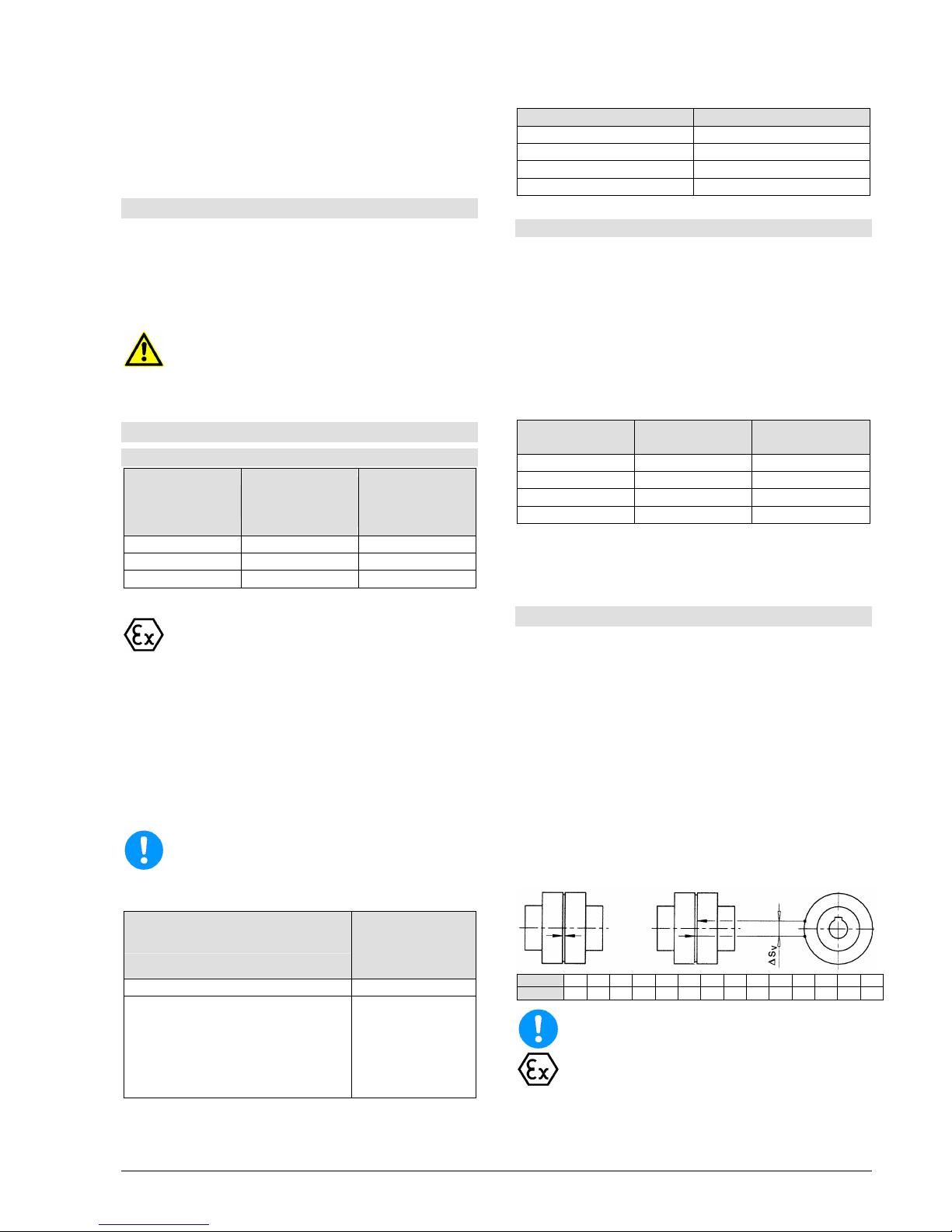
To measure the clearance in the coupling place a
mark on the O.D. of each coupling hub (see following
pic). Then fixing one hub, turn the opposite hub as far
as possible. Then measure the distance (∆SV)
between the marks of the coupling. If this measure
exceeds the value given in the chart, the packings
must be replaced. They must be replaced in sets.
Size 80 95 110 125 140 160 180 200 225 250 280 315 350 400
∆Sv [mm]
5,0 6,0 7,0 8,0 8,5 8,0 8,0 8,5 9,0 10,0 11,5 10,5 11,5 13,0
If wear is heavy, it must be assumed
that the
motor is not properly aligned with the pump or
that the distance between the coupling sections
has changed. Replace worn elements and re-
install or adjust coupling, as described in
chapter 5.3.
Page 22
Installation, Operating and Maintenance Instruction
Model LSN
LSN 100-english page 16
Revision 00
Article No 4264611
Issue 05/2003
7.6 Cleaning of pump
The pump must not be cleaned with pressur
ised
water - water will get into the bearings.
Dirt on the outside of the pump has an adverse
effect on transmission of heat. The pump should
therefore be cleaned with water at regular
intervals (depending on the degree of dirt).
Radial-Shaft sealings (421.41 and 421.51) are not
completely free from leakage. Impurities could
cause leakage at the shaft sealing area of the
frame. Therefore wipe off impurities with a rag
from time to time.
Replace dirty oil level sight glass (642).
8. Dismantling and repair of pump
8.1 General remarks
Repair to the pump or pump system may only
be carried out by authorised skilled personnel or
by the manufacturer´s specialist staff.
When disassembling the pump pay attention to
chapter 2 and chapter 4.1.
For mounting and repair you can order specialized
personnel if you want.
If dangerous liquids are pumped the appropriate
disposal of the handled liquid is necessary
be
fore the disassembly of the pump. Pay
attention to the fact, that even in dr
ained pumps
there are remainders of the handled liquid. If
necessary the pump must be flushed or
decontaminated. Laws must be observed,
otherwise danger to health is existing!
Before the disassembly the pump has to be
secured in such a way, that it can´t be started.
The pump casing must be drained and without
pressure.
All locking devices in the suction- and discharge-
pipe must be closed.
All parts must have taken on the temperature of
the environment.
Secure disassembled pumps, units or single
parts against tipping over or rolling off.
While disassembling the pump use of an open
flame (blowlamp, etc.) only, when there is no
danger of setting fire, cause an explosion or
cause injurious vapours.
Never apply heat to remove the impeller nut.
Use of hea
t may result in severe physical injury
and property damage.
Use original spare parts only. Pay attention to
the right materials and the matching design.
8.2 General
Works, which require shocks (hammer), must
only be performed outside the explosive
atmosphere or only non-
sparking tools must be
used.
Carry out disassembly and mounting according to the
appropriate sectional drawing.
You will only need common tools.
Before disassembly check if required parts are ready.
Disassemble the pump only so far, as required for the
replacement of the repair part.
8.3 Disassembly of Back Pull Out
Assembly
The Back Pull Out Assembly includes all parts of the
pump except the volute casing (102V). As the pumps
are constructed for process design the volute casing
(102V) can stay on the base frame and in the pipes,
unless the volute casing itself must be repaired.
Drain volute casing (102V) through the drain plug
(912.11).
Unscrew pipe unions of all flush- and cooling-
water-pipes and drain lubrication oil from bearing
bracket (330) via the screwed plug (903.51).
Remove coupling guard.
Remove spacer of the spacer type coupling.
Loosen screws for support foot (183) from the
base frame.
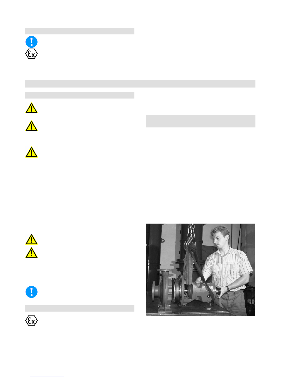
Hang the Back Pull Out Assembly onto a lifting
device, so that it won´t sink down or press into the
volute casing during the dismounting. Example
see picture 9 for lifting recommendations.
pic 9
Loosen hexagen head bolt (901.11) from the
casing.
Using the jack screws provided (901.42), separate
the Back Pull Out Assembly from the casing.
Page 23
Installation, Operating and Maintenance Instruction
Model LSN
LSN 100-english page 17
Revision 00
Article No 4264611
Issue 05/2003
8.4 Removal of Impeller
Note attached "Mounting Instruction for Shaft
Sealing".
If the impeller has back vanes check the axial
clearance "a" between the impeller (230) and
casing cover (161) before you continue the
dismounting. Refer to sect. 8.7.1.
Loosen impeller nut (922) (right threaded) by fixing
the rotor at the coupling end.
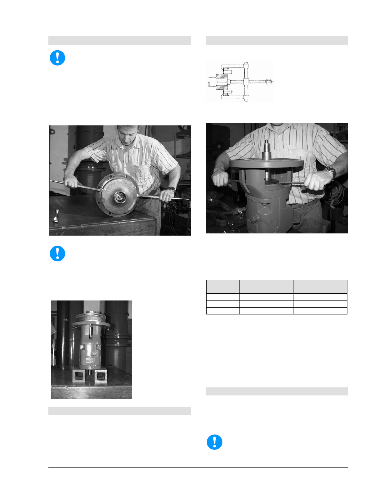
Draw off the impeller (230) with two screw drivers
or pry bars (picture 10). Remove key (940.31).
pic 10
Be sure to locate pry bars
under impeller vanes
to prevent damage to the impeller.
For further dismounting the Back Pull Out
Assembly should be placed in the vertical position
(with vertical shaft, see picture 11). Attention:
Precautions should be taken to prevent the Back
Pull Out Assembly from tipping!
pic 11
8.5 Removal of Shaft Sealing
Before you remove casing cover notice "Mounting
Instructions for Shaft Sealing".
Unfasten hexagonal nut (902.32) (not available on
all pump sizes) and take casing cover (161) out of
bearing bracket (344).
8.6 Removal of Bearing
Remove coupling with a coupling puller (picture
12), remove coupling key (940.52).
pic 12
Remove the flinger (507) axially by using 2 screw
drivers (see pic 13).
pic 13
Loosen hexagen head bolt (901.41). Remove the
bearing bracket lantern from bearing bracket
(330).
Dismount circlip (932.51). Therefore you need a
snap ring plier acc. to DIN 5256-C.
Bearing
bracket
required snap ring
plier
length i (min.) of
snap ring plier
24 size 94/C 40 200mm
32, 42 size 94/C 85 250mm
48 Größe 94/C 85 300mm
Remove shaft (210) including anti-friction bearing
(320.51 and 320.52) and bearing nut (923.51)
from the bearing bracket (330).
Remove the bearing nut (923.51). The bearing nut
is right hand threaded and self locking. It can be
reused 5 times if it is handled appropriately.
Remove the anti-friction bearing (320.51 and
320.52) from the shaft (210) using a hydraulic
press or a bearing puller.
8.7 Reconditioning
After disassembly all parts must be cleaned and
checked for wear carefully. Worn or damaged parts
must be replaced by new parts (spare parts).
When reassembling the pump it is recommended to
replace all seals.
All PTFE-
sealing elements and graphite
sealings are intended for being used only once.
Page 24
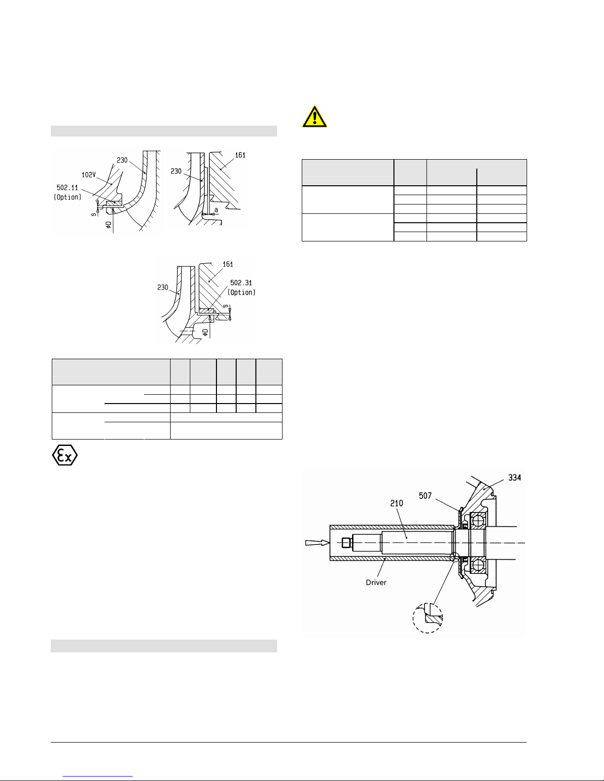
Installation, Operating and Maintenance Instruction
Model LSN
LSN 100-english page 18
Revision 00
Article No 4264611
Issue 05/2003
In most cases it make sense, if damaged absolutely
necessary, to renew the mechanical seal and the
bearings.
Deposits on the impeller (230), in the volute casing
(102V) or on the casing cover must be removed.
8.7.1 Clearance at impeller
Suction side of impeller Back vanes of impeller
Drive side of impeller
Only for pump sizes
100-65-315
125-80-315
125-80-400
125-100-315
125-100-400
150-125-315
150-125-400
200-150-315
200-150-400
Nominal diameter D (mm)
60
68
85
100
120
135
155
175
220
min. 0,15 0,17 0,20 0,22 0,25
new
max. 0,19 0,22 0,24 0,27 0,30
Radial
clearance s
(mm)
wear limits 0,78 0,85 0,90 1,05 1,15
new 0,8 - 1,2 Axial
clearance a
(mm)
wear limits max. 1,7
When the wear limits
has been reached or
exceeded, the worn parts must be replaced.
For volute casings (102V) with a wear ring (502.11)
and cover casings (161) with a wear ring (502.31)
there are the following possibilities to restore the
correct clearance:
a) Renew impeller (230) and wear ring. Then the
original measures are restored.
b) A customized wear ring (bored to fit) can be
supplied to avoid replacement of the impeller.
Please contact factory for details.
When volute casing (102V) or casing cover (161)
without wear ring must be repaired, a wear ring can be
installed to renew pump performance. Remachining of
the volute casing and /or casing cover is required.
Please contact the factory for details and assistance.
8.8 Mounting
Re-assemble the pumps using the reverse order of
steps as completed for pump disassembly. However
the following observations should be considered:
Pay attention to the utmost cleanliness when
reassembling the pump.
For tight tolerances, e.g. between shaft sleeve
(433) and shaft (210) or impeller (230) and shaft
(210), as well as thread, use a suitable anti-galling
compound (e.g. Molykote/Never-Seeze), so that
the assembly and the next disassembly will be
easier.
Anti-
galling compound must be compatible with
the pumpage.
Screws should be tightened, with the following
torque:
Screw torque in Nm
Location
Screw
Size
Lubricated
threads
Dry threads
M12 35 50
M16 105 150
Casing screws
M20 210 305
M10 35 50
M12 60 90
All other screws
M16 150 220
Before mounting the second bearing on the shaft
push in the circlip (932.51) between the two
bearings.
Before mounting new bearings, warm them up to
80°C in an oil bath or using a bearing heater. If
necessary use a tube to force the inner ring onto
the shaft by gentle taps with a hammer. Hold the
outer ring to avoid vibrations of the balls.
When bolting together the bearing bracket (330)
with the bearing bracket lantern (344) and the
bearing bracket lantern with the volute casing
(102V), screws should be positioned in the centre
of the drilled holes. Failure to do so could result in
improper oil setting.
Push the flinger (507) onto the shaft (210) till it
rests axially against the shoulder of the shaft.
Between flinger (507) and Bearing bracket lantern
(344) there must remain a clearance of at least
0,7 mm.
If necessary you can use a driver for mounting
(see picture 14).
pic 14
Do not use excessive force.
For mounting of the shaft sealing (packing or
mechanical sealing) see separate description
"Mounting Instruction of Shaft Sealing" and
chapter 8.5.
For impellers with back vanes the axial clearance
between the back vanes and the casing cover
Page 25
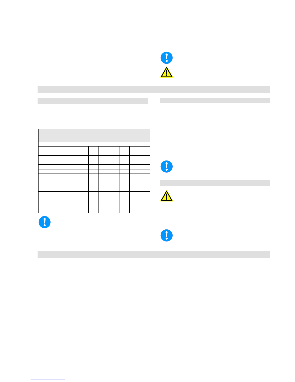
Installation, Operating and Maintenance Instruction
Model LSN
LSN 100-english page 19
Revision 00
Article No 4264611
Issue 05/2003
(161) should be checked after mounting the
impeller (230) and tightening the impeller nut (922)
(see chapter 8.7.1).
After the mounting of the back pull out assembly,
and its assembly into the volute casing, turn the
shaft and control the free moving of the pump in
this way. The shaft sealings will cause slightly
resistance when turning, but there must not be
any contact between metal parts.
Before starting the pump check alignment of the
coupling. This can be dropped on pumps with
spacer coupling, if pump casing and motor were
not disassembled.
Before starting the pump do not forget to fill in
oil!
Before starting the pump
do not forget to install
and connect all security devices.
9. Recommended Spare Parts, Spare Pumps
9.1 Spare Parts
Spare parts should be selected to last for two-years
continuous operation. If no other guidelines are
applicable, we recommend that you stock the number
of parts listed below (in accordance with DIN 24296).
Number of pumps
(incl. stand-by pumps)
2 3 4 5 6/7 8/9 10/+
Spare Parts Number of Spare Parts
Impeller 1 1 1 2 2 2 20%
Wear ring 2 2 2 3 3 4 50%
Shaft with key and nuts 1 1 1 2 2 2 20%
Ball Bearing set 1 1 2 2 2 3 25%
Shaft sleeve 2 2 2 3 3 4 50%
Lantern ring 1 1 2 2 2 3 30%
Packing ring 16 16 24 24 24 32 100%
Joints for pump casing
sets
4 6 8 8 9 12 150%
other joints sets 4 6 8 8 9 10 100%
Mech. Seals
set 1 1 2 2 2 3 25%
Bearing (lantern with
bearing bracket,
complete with shaft,
bearings, aso.)
- - - - - - 2
To ensure optimum availability, we recommend
that suitable quantities of spare pa
rts are held in
stock, especially if these are made from special
materials and in the case of mechanical seals,
because of the longer delivery times.
Spare Parts Order
When ordering spare parts, please supply the
following information:
Type:
______________________________________________________________________
S/N (Order No.):
_
___________________________________________________
Part name:
_____________________________________________________________
Sectional Drawing
__________________________________________________
All the information is given in the data sheet and the
relevant sectional drawing.
Store spare parts in dry and clean rooms!
9.2 Stand-by pumps
It is essential that a sufficient number of standby pumps are kept ready for use in plants whe
re
failure of a pump could endanger human life or
cause damage to property or high costs.
Regu
lar checks should be carried out to ensure
that such pumps are always ready for use (see
chapter 6.8).
Store stand-by pumps according to chapter 6.8.
10. Faults - Causes and Solutions
The following notes on causes of faults and how to
repair them are intended as an aid to recognising the
problem. The manufacturer's Customer Service
Department is available to help repair faults that the
operator cannot or does not want to repair. If the
operator repairs or changes the pump, the design data
on the Data Sheet and chapter 2 of these Operating
Instructions should be particularly taken into account.
If necessary, the written agreement of the
manufacturer must be obtained.
Page 26
Installation, Operating and Maintenance Instruction
Model LSN
LSN 100-english page 20
Revision 00
Article No 4264611
Issue 05/2003
Discharge too low
Discharge stops after a time
Head too low
Head too high
Drive mechanism overloaded
Pump not running quietly
Temperature in pump too high
Temperature in shaft sealing too high
Temperature at the bearing too high
Pump leaking
Leakage rate at shaft sealing too high
Cause
Solution
■
Back-pressure too high
check facility for pollution, open discharge valve
reduce resistance in discharge pipe (e.g. clean filter if
necessary)
use larger impeller (note available motor power)
■ ■
■
Back-pressure too low, discharge too low throttle discharge valve
■ ■
Speed too high reduce speed
compare speed of motor with specified pump speed (rating
plate)
when adjusting speed (frequency transformer) check refer-
ence value setting
■ ■
Speed too low increase speed (check available motor power)
compare speed of motor with specified pump speed (rating
plate)
when adjusting speed (frequency transformer) check reference
value settings
■ ■
■ ■
Flow too little increase min. flow (open discharge valve, bypass)
■
Flow too big reduce flow (throttle discharge valve)
■ ■
Impeller diameter too big use smaller impeller
■ ■
Impeller diameter too small use larger impeller (check available motor power)
■ ■
■ ■
Pump and/or pipes not completely filled with liquid fill
vent
■ ■ ■
Pump or suction/intake pipe blocked clean
■ ■
Air pocket in pipeline vent
improve course of pipe
■ ■ ■
■ ■
Suction height too big / NPSH of system too small
increase liquid level and admission pressure
reduce resistance in the intake/suction pipe (change course
and rated width, open shut-off valves, clean filters)
■ ■ ■
Air being sucked in increase liquid level
check if suction pipe is vacuum-tight
■ ■ ■
Air being sucked in through shaft sealing clean sealing pipe
increase sealing pressure
replace shaft sealing
■ ■
Direction of rotation is wrong swap over two phases of power supply (to be done by an
electrician)
■ ■
■
■
Inner components suffering from wear replace worn parts
■ ■ ■
Density and/or viscosity of liquid handled is too high seek assistance
■ ■ Stuffing box not straight tighten evenly
■
Stuffing box is fastened too tight resp. shaft sealing is worn loosen stuffing box
replace packing and/or mechanical seal
check sealing, flushing and cooling pipes (pressure)
avoid dry running
■
■ Lines and roughness on shaft or shaft sleeve replace parts
■
■ Unsuitable packing material use suitable material (check shaft or shaft sleeve for damage
beforehand)
■
■ Deposits on mechanical seal
clean
replace mechanical seal if necessary
if necessary provide additional rinsing or quench
■
■ Impeller out of balance
remove blocks/deposits
replace impeller if broken or unevenly worn
check shafts to ensure that they are running true
■
■ ■
Coupling not aligned align pump unit better
■
■
Coupling distance too small change
■ ■
■ ■ ■
Forces in pipeline too high (pump unit under strain) change (support pipes, use compensators, etc.)
is foundation plate/frame properly cast in place?
■
Too much, too little or the wrong type of lubricant change
■ Electricity supply not right (2-phase running) check voltage of all phases
check cable connections and fuses
■ Sealing insufficient tighten screws
replace sealing
■
■
Bearing damaged replace
check lubricant and bearing space for pollutants (rinse oil area)
■
Relief fittings insufficient
clean relief openings in impeller
replace worn parts (impeller, split rings)
adjust in line with the system pressure/intake pressure given on
ordering
■
System-related vibrations (resonance) seek assistance
 Loading...