

ITT ICB Installation, Operation And Maintenance Instructions

Goulds Pumps
Artikel Nr. 771076102 Rev. 02 01/2010
en
Goulds-Volute Casing Pumps
Model: ICB
Installation, Operation and Maintenance Instruction
Translation of the Original Operation Manual
en
Keep for further use !
Pay attention to this operating instruction before the delivery, installation, start-up a.s.o.!
© ITT Austria GmbH

Installation, Operation and Maintenance Instruction
Model ICB
ICB 100-english page 1
Revision 02
Article No 771076102
Issue 01/2010
TABLE of CONTENTS
Pump Name Plate ..................................................... 2
ATEX-Label (only for pumps in compliance with
EC directive 94/9/EG)................................................ 2
1. General................................................................... 3
1.1 Guarantee ......................................................... 3
2. Safety Regulations ............................................... 3
2.1 Marking of References in the Operating
Instructions.............................................................. 3
2.2 Dangers of non-observance of the Safety
Instructions.............................................................. 4
2.3 Safety Instructions for the Operator / Worker ... 4
2.4 Safety Instructions for Maintenance, Inspections
and Mounting Work ................................................. 4
2.5 Unauthorized Alteration and Spare Parts
Production ............................................................... 4
2.6 Undue Operation............................................... 4
2.7 Explosion Protection.......................................... 4
2.8 Use acc. to Regulations .................................... 6
3. Description ............................................................ 6
3.1 Design ............................................................... 6
3.1.1 Design Coding System................................... 6
3.2 Shaft Sealing..................................................... 7
3.3 Bearing.............................................................. 7
3.4 Approximate Value for Sound Pressure Level .. 7
3.5 Permitted Nozzle Loads and Torques at the
Pump Nozzles ... ..................................................... 7
3.6 Permitted pressures and temperatures............. 8
3.7 Condensate....................................................... 9
4. Transport, Handling, Storage .............................. 9
4.1 Transport, Handling........................................... 9
4.2 Storage / Conservation...................................... 9
5. Mounting / Installation ......................................... 9
5.1 Mounting of Pump / Unit.................................... 9
5.2 Connection of Pipings to the Pump................. 10
5.3 Drive................................................................ 10
5.4 Electric Connection ......................................... 10
5.5 Final Control.................................................... 11
6. Start-up, Operation, Shut down ........................ 11
6.1 Initial start-up................................................... 11
6.2 Switch on drive................................................ 11
6.3 Restarting ........................................................11
6.4 Limits of Operation ..........................................11
6.5 Lubrication .......................................................12
6.6 Monitoring........................................................12
6.7 Shutting down..................................................12
6.8 Storage / longer periods of non-operation ....... 12
7. Servicing, Maintenance ......................................13
7.1 General remarks..............................................13
7.2 Mechanical seals .............................................13
7.3 Motor bearings.................................................13
7.4 Cleaning of pump ............................................13
8. Dismantling and repair of pump ........................13
8.1 General remarks..............................................13
8.2 General............................................................13
8.3 Removal and Installation of screen in the motor
lantern....................................................................13
8.4 Removal of the Back Pull Out Assembly ......... 14
8.5 Removal of Impeller.........................................14
8.6 Removal of Shaft Sealing ................................14
8.7 Removal of Stub Shaft.....................................14
8.8 Reconditioning.................................................15
8.9 Mounting..........................................................15
9. Spare parts, Spare pumps..................................16
9.1 Spare parts ......................................................16
9.2 Stand-by pumps...............................................16
10. Faults - Causes and Solutions.........................17
11. Motor Operating Instructions ..........................18
Installation Manual - Single mech. seal without shaft
sleeve (Design code S1..2) .......................................20
Installation Manual - Single mech. seal with quench
without shaft sleeve (Design code S4..2) ………...... 22
Sectional drawing pump unit (Design code S1..2),
Impeller with back vanes.......................................... 25
Sectional drawing pump unit (Design code S1..2),
Impeller with balancing holes ................................... 26
Sectional drawing pump unit (Design code S4..2),
Impeller with back vanes.......................................... 27
Sectional drawing pump unit (Design code S4..2),
Impeller with balancing holes ................................... 28
Connections ............................................................. 29
Dimensional drawing................................................ 30
Installation, Operation and Maintenance Instruction
Model ICB
ICB 100-english page 2
Revision 02
Article No 771076102
Issue 01/2010
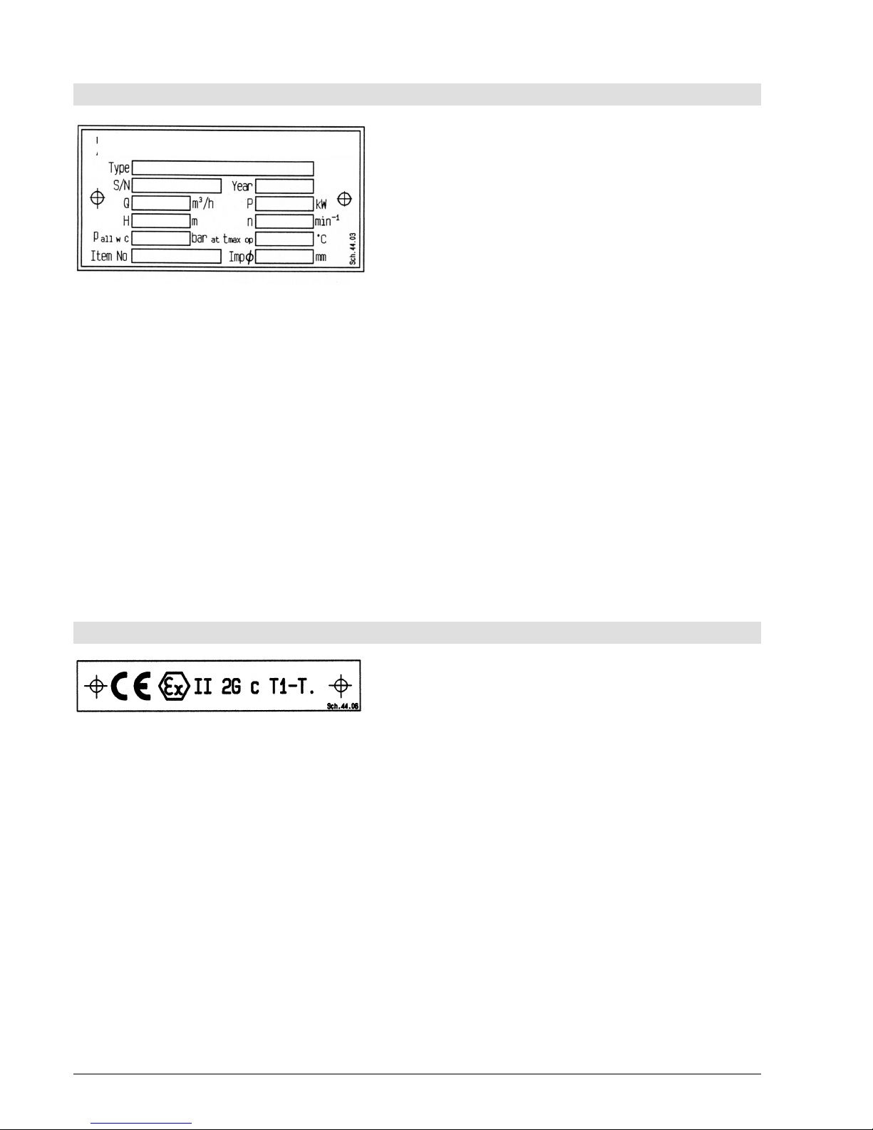
Pump Name Plate
Type *) Type of pump
S/N *) Serial number
Year Year of construction
Q Rated capacity at the operating point
P Rated power at the operating point
H Head (Energy head) at the operating point
n Speed
p
all w C
Max. permitted casing-operation-pressure
(=highest discharge pressure at the rated
operating temperature to which the pump
casing can be used).
t
max op
Maximum permitted operating temperature of
pumped liquid
Item No Customer related order number
Imp∅ Outer diameter of the impeller
*) All details of design and materials are defined with
this information. They must be stated on all inquiries to
the manufacturer resp. orders of spare.
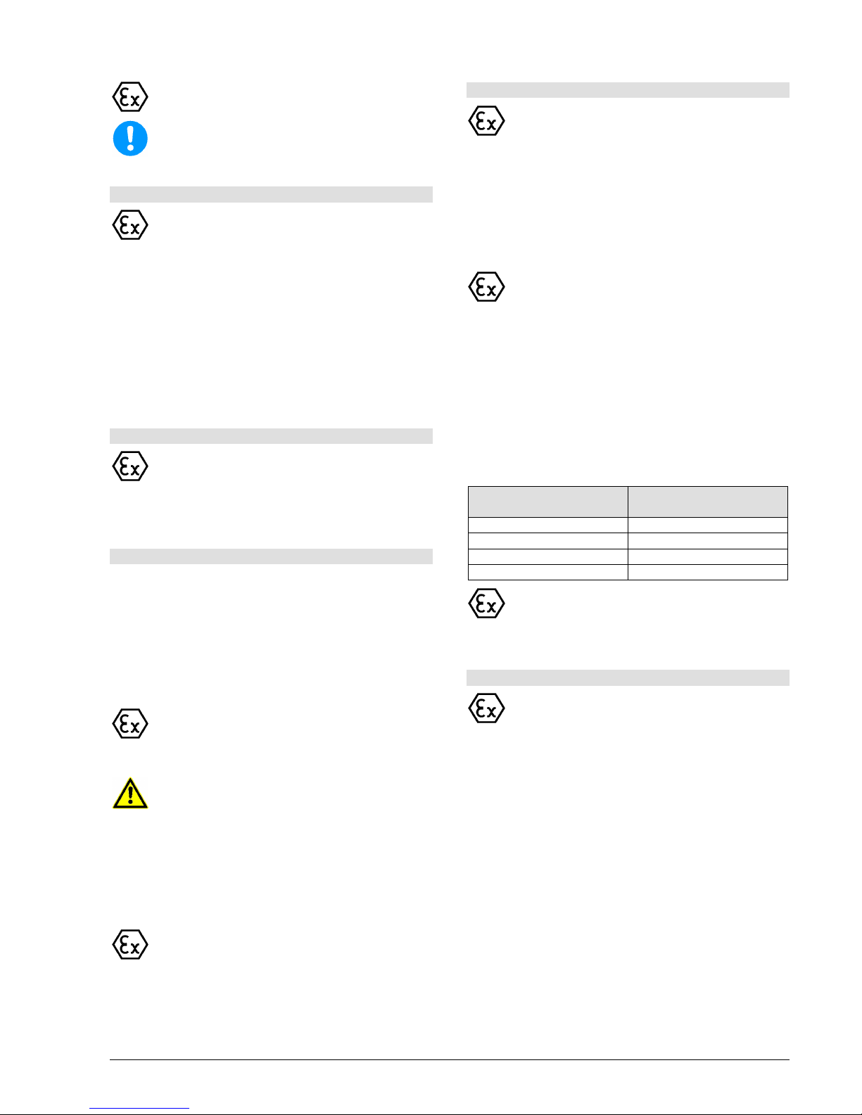
ATEX-Label (only for pumps in compliance with EC directive 94/9/EG)
CE Marking of compliance with the EC directive
94/9/EG
Ex specific marking for explosion protection
II Symbol for the appliance group
2G Symbol for the category (2), explosive
atmosphere due to gases, vapors or mist (G)
c Symbol for used ignition protection
(constructual safety "c")
T1-T. Symbol for classification of the theoretically
available range of the temperature classes -
data for temperature class refer to chapter
2.7.5; Data for maximum permitted
temperature of pumped liquid refer to pump
name plate, data sheet and / or order
confirmation.
The conformity with the EC directive 94/9/EG
"Appliances and Protection Systems for designated
use in areas endangered to explosion" is declared by
the issue of the EC-Declaration of Conformity and the
attachment of the ATEX-label at the pump (adapter).
The ATEX-label is attached additionally to the pump
name plate.

Installation, Operation and Maintenance Instruction
Model ICB
ICB 100-english page 3
Revision 02
Article No 771076102
Issue 01/2010
1. General
This product corresponds with the requirements of the
Machine directive 2006/42/EG.
The staff employed on installation, operation,
inspection and maintenance must be able to
prove that they know about the relevant
accident preven
tion regulations and that they
are suitably qualified for this work. If the staff
does not have the relevant knowledge, they
should be provided with suitable instruction.
The operation safety of the delivered pump resp. unit
(= pump with motor) can only be guaranteed on
designated use according to the attached data sheet
and / or order confirmation resp. chapter 6 "Start-up,
Operation, Shut down".
The operator is responsible for following the
instructions and complying with the safety
requirements given in these Operating Instructions.
Smooth operation of the pump or pump unit can only
be achieved if installation and maintenance are carried
out carefully in accordance with the rules generally
applied in the field of engineering and electrical
engineering.
If not all the information can be found in these
Operating Instructions, please contact us.
The manufacturer takes no responsibility for the pump
or pump unit if the Operating Instructions are not
followed.
These Operating Instructions should be kept in a safe
place for future use.
If this pump or pump unit is handed on to any third
party, it is essential that these Operating Instructions
and the operating conditions and working limits given
in the Confirmation of Order are also passed on in full.
These Operating Instructions do not take into account
all design details and variants nor all the possible
chance occurrences and events which might happen
during installation, operation and maintenance.
We retain all copyright in these Operating Instructions;
they are intended only for personal use by the owner
of the pump or the pump unit. The Operating
Instructions contain technical instructions and
drawings which may not, as a whole or in part, be
reproduced, distributed or used in any unauthorised
way for competitive purposes or passed on to others.
1.1 Guarantee
The guarantee is given in accordance with our
Conditions of Delivery and / or the confirmation of
order.
Repair work during the guarantee period may only be
carried out by us, or subject to our written approval.
Otherwise the guarantee ceases to apply.
Longer-term guarantees basically only cover correct
handling and use of the specified material. The
guarantee shall not cover natural wear and tear and all
parts subject to wear, such as impellers, shaft
sealings, shafts, shaft sleeves, bearings, wear rings
etc. or damage caused by transport or improper
handling.
In order for the guarantee to apply, it is essential that
the pump or pump unit is used in accordance with the
operating conditions given on the name plate,
confirmation of order and in the data sheet. This
applies particularly for the endurance of the materials
and smooth running of the pump and shaft sealing.
If one or more aspects of the actual operating
conditions are different, we should be asked to
confirm in writing that the pump is suitable.
2. Safety Regulations
These Operating Instructions contain important
instructions which must be followed when the pump is
assembled and commissioned and during operating
and maintenance. For this reason, these Operating
Instructions must be read by the skilled staff
responsible and / or by the operator of the plant before
it is installed and commissioned, and they must be left
permanently available at the place where the pump or
pump unit is in use.
These Operating Instructions do not refer to the
General Regulations on Accident Prevention or
local safety and / or operating regulations. The
operator is responsible for complying with these
(if necessary by calling in additional installation
staff).
Equally, instructions and safety devices regarding
handling and disposal of the pumped media and/or
auxilliary media for flushing, lubrication a.s.o.,
especially if they are explosive, toxical, hot a.s.o., are
not part of this operating instruction.
For the competent and prescribed handling only the
operator is responsible.
2.1 Marking of References in the
Operating Instructions
The safety regulations contained in these Operating
Instructions are specially marked with safety signs
acc. to nach DIN 4844:
Safety reference!
Non-
observance can impair the pump and its
function.
EC-Ex Marking
Products intended for use in explosive
atmospheres must be marked.
General Symbol for Danger!
Persons can be endangered.
Warning of electric voltage!

Installation, Operation and Maintenance Instruction
Model ICB
ICB 100-english page 4
Revision 02
Article No 771076102
Issue 01/2010
Safety instructions attached directly to the pump resp.
unit must be followed under any circumstances.
Further they must be kept in good readable condition.
In the same way, as these Operating Instructions
of the pump, all possibly attached Operating
Instructions of accessories (e.g. motor) must be
noticed and kept available.
2.2 Dangers of non-observance of the
Safety Instructions
Non-observance of the Safety Instructions can
lead to loss of any claim for damages.
Further, non-observance can lead to following risks:
Failure of important functions of the machine or
facility.
Failure of electronic appliances and measuring
instruments by magnetic fields.
Endangering of persons and their personal
property by magnetic fields.
Endangering of persons by electric, mechanic and
chemical influences.
Endangering of environment through leakage of
dangerous substances.
On application of the unit in areas endangered
to explosion special attention must be paid to
sections marked with Ex.
2.3 Safety Instructions for the Operator /
Worker
Depending on the operating conditions, wear and
tear, corrosion or age will limit the working life of
the pump/pump unit, and its specified
characteristics. The operator must ensure that
regular inspection and maintenance are carried
out so that all parts are replaced in good time,
which would otherwise endanger the safe
operation of the system. If abnormal operation or
any damage are observed, the pump must cease
operation immediately.
If the breakdown or failure of any system or unit
could lead to people being hurt or property being
damaged, such system or unit must be provided
with alarm devices and/or spare modules, and
they should be tested regularly to ensure that they
function properly.
If there is any risk of injury from hot or cold
machine parts, these parts must be protected
against contact by the user, or suitable warning
signs must be affixed.
Contact protection on moving parts (e.g. coupling
guards) must not be removed from systems that
are in operation.
If the sound level of a pump or pump unit is above
85 dB(A) an ear protection has to be used when
staying near the pump for some time.
If dangerous media (e.g. explosive, toxic, hot) leak
out (e.g. from shaft seals), these must be directed
away so that there is no danger to people or the
environment. The provisions of the law must be
observed.
Measures should be taken to exclude any danger
from electricity (e.g. by complying with the local
regulations on electrical equipment). If work is
carried out on live electrical components, they
should be unplugged from the mains or the main
switch turned off and fuse unscrewed. A motor
protection switch is to be provided.
2.4 Safety Instructions for Maintenance,
Inspections and Mounting Work
The operator is responsible that any maintenance,
inspections and mounting work is made by
authorized competent personnel, which must be
informed by having read the Operating
Instructions.
Basically, all work on the pump or pump unit
should only be carried out when the pump is
stationary and not under pressure. All parts must
be allowed to return to ambient temperature.
Make sure that no-one can start the motor during
such work. It is essential that the procedure for
stopping the system described in the Operating
Instructions is observed. Pumps or pump systems
that carry media that are dangerous to health must
be decontaminated before being taken apart.
Safety Data Sheets for the various liquids handled.
Immediately after finishing work, all safety and
protective devices must be replaced or restarted.
2.5 Unauthorized Alteration and Spare
Parts Production
Alteration or changes of the machine are permitted
after agreement with the manufacturer.
Original spare parts and accessory authorized by the
manufacturer are serving the safety.
The use of other parts can lead to loss of liability for
therefrom resulting consequences.
2.6 Undue Operation
The operating safety of the delivered machine can
only be guaranteed by designated use acc. to the
following chapters of the Operating Instructions.
The limits stated in the data sheet and / or order
confirmation must not be exceeded under any
circumstances.
2.7 Explosion Protection
On application of units in areas endangered to
explosion measures and references in the chapters
2.7.1 to 2.7.6 must be observed, so that explosion
protection is guaranteed.
2.7.1 Filling of unit
During operation of the pump the system of the
suction and pressure pipe and the pump itself
must permanently be filled with the pumped
liquid.
Thus, no explosive atmosphere can develop
and the danger of dry-run is avoided.
Installation, Operation and Maintenance Instruction
Model ICB
ICB 100-english page 5
Revision 02
Article No 771076102
Issue 01/2010
If the operator can´t guarantee that, according
monitoring measures must be provided.
Equally all seal casings, auxiliary systems of the
shaft sealing, as well as heating and cooling
systems must be filled carefully.
2.7.2 Marking
The marking of the pump refers to the pump
itself. For the motor resp. further addi
tions a
separate Declaration of Conformity, as well as a
corresponding marking must be available.
Example of of marking at pump:
CE Ex II 2 G c T1-T.
The marking shows the theoretically applicable range
of temperature classes. The different temperatures,
permitted acc. to pump design, result as shown in
chapter 2.7.5. The same is valid for the drive.
For a whole unit (pump, motor) with different
temperature classes the lowest is valid.
2.7.3 Rotation Control
If danger of explosion is also existing during
installation, the rotation control must not be
carried out by short start-
up of the empty pump,
to avoid undue temperature increase in case of
contact of rotating and stationary parts.
2.7.4 Operation of pump
The pump must only be started up with fully opened
suction side and slightly opened pressure side valve.
The start-up against closed non-return valve, however,
is possible. Immediately after the start-up the
discharge side valve must be adjusted to the operating
point.
Refer to chapter 6.2, as well.
Operation with closed valve in suction and / or
discharge pipe is not permitted!
There´s a danger, that high surface
temperatures are developing at th
e pump
casing after relatively short time, through fast
heating of the liquid inside the pump.
Fast pressure increase inside the pump can
lead to overload and, thus, the pump can burst.
In chapter 6.4.1 the minimum flow is stated. Longer
operating phases with these flows and the named
liquids don´t cause additional increase of surface
temperature at the pump.
Furthermore the references in chapter 6 of these
operating Instructions must be taken into
consideration.
On pumps with mech. seals the perm
itted
temperature limits can be exceeded due to dry-
run. Dry run not only can occur on insufficiently
filled seal casing, but also because of too much
gas in the medium.
Operation of the pump out of the permitted
operating range can lead to dry-run, as well.
2.7.5 Temperature limits
Under normal operating conditions the highest
temperatures must be expected at the surface
of the pump casing and in the area of the
bearings.
The surface temperature occurring at pump casing
corresponds with the temperature of the pumped
liquid.
In the area of lantern and motor free contact of
surface to environment must be given for proper
cooling.
During operation of the pump it must be
secu
red that an overabundant sedimentation of
dust is avoided (regular cleaning
), to prevent
heating of pump surface over the permitted
temperature.
The operator of the plant must secure that the
defined operating temperature is observed. The
max. allowed temperature of the pumped liquid at
suction depends on the particular temperature
class.
The following table shows the theoretical temperature
limits of the pumped liquid in consideration of the
temperature classes acc. to EN 13463-1.
Temperature class acc.
EN 13463-1
Temperature class acc.
EN 13463-1
T4 (135°C) 135°C
T3 (200°C) 140°C
T2 (300°C) 140°C
T1 (450°C) 140°C
The particular allowed operating temperature of
the pump is shown in the data sheet and / or the
order confirmation resp. the type plate at the
pump.
2.7.6 Maintenance
For a secure and reliable operat
ion it must be
secured by regular inspections, that the unit is
maintained competently and is kept in good
technical condition.
Example: Function of bearings. Operation and
application conditions are essentially responsible for
their achievable life cycle.
By regular control of the lubricant and the running
sound the danger of occurring over temperatures by
bearings running hot or defect bearing seals is
avoided. Refer to chapter 6.6 and 7.4.
The function of the shaft sealing must be secured by
regular control.
If auxiliary systems (e.g. external flushing, cooling,
heating) are installed, it must be checked, if monitoring
devices are necessary to secure the function.

Installation, Operation and Maintenance Instruction
Model ICB
ICB 100-english page 6
Revision 02
Article No 771076102
Issue 01/2010
2.7.7 Electric switches and control device,
Instrumentation and accessories
Electri
c switches and control devices,
instru
mentation and accessories must
correspond with the valid safety requirements
and regulations for explosion protection.
2.8 Use acc. to Regulations
2.8.1 Speed, Pressure, Temperature
Suitable safety measures must
be taken at the
plant to ensure that the speed, pressure and
temperature of the pump and the shaft sealing
do not exceed the limit values given in the data
sheet and / or order confirmation. The given
admission pressures (system pressures) must
also be sufficiently high.
Further, pressure shocks, as can occur on too fast
shut down of the facility, must be kept away from the
pump (e.g. by non-return valve at pressure side,
airtanks). Quick temperature changes must be
avoided. They could cause a temperature shock and
lead to damage or impair the function of single
components.
2.8.2 Permitted Nozzle Loads and Torques
Basically the suction and discharge piping must
be designed in such way, that as little forces as
possible are effective to the pump. If tha
t is not
possible, the values shown in chapter 3.5 must
not be exceeded under any circumstances. This
is valid for the operation as well as for the
standstill of the pump and therefore for all
pos
sible pressures and temperatures of the
unit.
2.8.3 NPSH
The pumped liquid must have a min. pressure
NPSH at the impeller inlet, so that cavitation
free work is secured resp. a "break off" of the
pump flow is prevented. This condition is
fulfilled, when NPSH-
value of the system
(NPSHA) lies above NPSH-value of
the pump
(NPSHR) under all operating conditions.
Attentention must especially be piad to the NPSHvalue on pumping liquids near the vapour pressure. If
the NPSH-value of the pump remains under, this can
lead from damage of the material due to cavitation to
destruction by overheating.
The NPSH-value of the pump (NPSHR) is shown in
the curves of every pump type.
2.8.4 Sealing, Flushing, Cooling
Suitable provisions for the regulation and monitoring of
sealing, flushing or cooling are to be provided.
When handling dangerous liquids or if temperatures
are high, care should be taken to ensure that the
pump ceases operating if the sealing, flushing or
cooling system fails.
Sealing, flushing and cooling systems must always be
operational before the pump is started up. They
should not be taken out of operation until the pump
has stopped, provided that the nature of the operation
allows this at all.
2.8.5 Back Flow
In systems where pumps are operating in closed
circuits under pressure (gas cushions, steam
pressure), the pressure of the gas cushion must not
be reduced via the pump, since the back flow speed
may be much higher than the operating speed, which
would destroy the unit.
3. Description
3.1 Design
ICB-pumps are single-stage volute casing pumps in
block design. Hydraulic design and dimensions comply
with ISO 2858/ EN 22858, the technical design
complies with ISO 5199/EN 25199.
The motors comply with DIN 42677-IM B5. Motor and
pump shaft are coupled rigidly.
The permitted application conditions and design
details of the delivered pump are shown in the
attached data sheet and / or the order confirmation
(see Design Coding System in chapter 3.2).
Installation position: ICB-pump are intended for use
with horizontal shaft, discharge up. Installation
positions deviating therefrom must be approved by the
manufacturer.
3.1.1 Design Coding System
Due to the coding on data sheet and / or order
confirmation all information regarding the delivered
pump can be found in this Installation, Operation and
Maintenance Instruction, e.g.:
ICB 100 - 65 - 250 S1 V L 2 - 132
(0) (1) (2) (3) (4)
(5) (6) (7) (8)
Position (0) - Name of Model
ICB - ISO block pump
Position (1) - Suction Nozzle in mm
Position (2) - Discharge Nozzle in mm
Position (3) - Nominal diameter of impeller in mm
Position (4) - Shaft sealing
S1 - Single-mech. seal acc. DIN 24960 l1k /
EN 12756 form U
S4 - Single-mech. seal acc. DIN 24960 l1k /
EN 12756 form U
with Quench (throttle bush)
Position (5) - Material Impeller
N = Cast Iron (0.6025)
L = Ductile Iron (0.7043)
V = Carbon Steel (1.4408)
W = Duplex (1.4517)

Installation, Operation and Maintenance Instruction
Model ICB
ICB 100-english page 7
Revision 02
Article No 771076102
Issue 01/2010
Position (6) - Material pump casing (same coding as
impeller, cast iron not available)
Position (7) - Stub shaft
2 - without shaft sleeve (Duplex 1.4462 std)
Position (8) - IEC Motor size
3.2 Shaft Sealing
Pumps of design ICB are exclusively sealed with
single mech. seals with installation dimensions acc. to
EN 12756 (DIN 24960), design "K", form "U".
Two shaft sealing variants are available. On the data
sheet and / or the order confirmation the kind of shaft
sealing is given. An instruction for the mounting and
operation of mech. seals is contained in the particular
"Mounting Instruction of Shaft Sealing".
For nominal size (d1) of the mech. seal refer to
following chart.
Type
nom. size
d1 of mech.
seal
Type
nom. size
d1 of mech.
seal
40-25-160 33
100-65-160 43
40-25-200 33
100-65-200 43
40-25-250 43
100-65-250 43
50-32-160 33
100-65-315 53
50-32-200 33
125-80-160 43
50-32-250 43
125-80-200 43
50-32-315 43
125-80-250 43
65-40-160 33
125-80-315 53
65-40-200 33
125-100-200 43
65-40-250 43
125-100-250 53
65-40-315 43
125-100-315 53
80-50-160 33
150-125-250 53
80-50-200 33
150-125-315 53
80-50-250 43
200-150-250 53
80-50-315 43
The
mech. seal used in the standard design is
not resistant to mineral oils.
For further details about mech. seals, as well as
the dangers of accidents, connected to them
refer to chapter 6.6 and chapter 7.2.
3.3 Bearing
The shaft is guided by the ball bearings of the motor.
The bearings are grease lubricated for life and,
therefore maintenance-free.
3.4 Approximate Value for Sound
Pressure Level
Sound pressure level LpA in dB(A)
Pump alone Pump + Motor
Nominal
power
PN
in kW
2950
min-1
1450
min-1
975
min-1
2950
min-1
1450
min-1
975
min-1
0,55 50,5 49,5 49,0 58,0 52,0 51,5
0,75 52,0 51,0 50,5 59,0 54,0 53,0
1,1 54,0 53,0 52,5 60,0 55,5 54,5
1,5 55,5 55,0 54,5 63,5 57,0 56,0
2,2 58,0 57,0 56,5 64,5 59,0 58,5
3,0 59,5 58,5 58,0 68,5 61,0 62,0
4,0 61,0 60,0 59,5 69,0 63,0 63,0
5,5 63,0 62,0 61,5 70,0 65,0 65,0
7,5 64,5 63,5 63,0 70,5 67,0 67,0
11,0 66,5 65,5 65,0 72,0 69,0 68,5
15,0 68,0 67,0 66,5 72,5 70,0 70,5
18,5 69,0 68,5 68,0 73,0 70,5 74,0
22,0 70,5 69,5 69,0 74,5 71,0 74,0
30,0 72,0 71,0 - 75,0 72,0 37,0 73,0 - - 76,0 - -
Sound pressure level LpA measured in 1 m distance
from pump surface acc. to DIN 45635, part 1 and 24.
Room and foundation influences are not considered.
The tolerance for these values is ±3 dB(A).
Addition with 60 Hz-operation:
Pump alone: −
Pump with motor: +4 dB(A)
3.5 Permitted Nozzle Loads and Torques
at the Pump Nozzles ...
... following the Europump-Recommendation for
pump acc. to ISO 5199.
The data for forces and torques are only valid for static
piping loads.
All values for forces and torques refer to standard
materials EN-GJS400-18LT and 1.4408.
pic 1

Installation, Operation and Maintenance Instruction
Model ICB
ICB 100-english page 8
Revision 02
Article No 771076102
Issue 01/2010
Suction nozzle Discharge nozzle
Forces in N Torques in Nm Forces in N Torques in Nm Sizes
∅DN
Fx Fy Fz
∑F
Mx My Mz
∑M
∅DN
Fx Fy Fz
∑F
Mx My Mz
∑M
40-25-160 40 700 620 560 1100 730 500 590 1070 25 420 400 480 730 500 340 400 730
40-25-200 40 700 620 560 1100 730 500 590 1070 25 420 400 480 730 500 340 400 730
40-25-250 40 700 620 560 1100 730 500 590 1070 25 420 400 480 730 500 340 400 730
50-32-160 50 920 840 760 1450 780 560 650 1150 32 500 480 590 930 620 420 480 900
50-32-200 50 920 840 760 1450 780 560 650 1150 32 500 480 590 930 620 420 480 900
50-32-250 50 920 840 760 1450 780 560 650 1150 32 500 480 590 930 620 420 480 900
50-32-315 50 920 840 760 1450 780 560 650 1150 32 500 480 590 930 620 420 480 900
65-40-160 65 1180 1040 950 1850 840 620 670 1230 40 620 560 700 1100 730 500 590 1060
65-40-200 65 1180 1040 950 1850 840 620 670 1230 40 620 560 700 1100 730 500 590 1060
65-40-250 65 1180 1040 950 1850 840 620 670 1230 40 620 560 700 1100 730 500 590 1060
65-40-315 65 1180 1040 950 1850 840 620 670 1230 40 620 560 700 1100 730 500 590 1060
80-50-160 80 1400 1260 1150 2200 900 650 730 1320 50 840 760 920 1450 780 560 650 1150
80-50-200 80 1400 1260 1150 2200 900 650 730 1320 50 840 760 920 1450 780 560 650 1150
80-50-250 80 1400 1260 1150 2200 900 650 730 1320 50 840 760 920 1450 780 560 650 1150
80-50-315 80 1400 1260 1150 2200 900 650 730 1320 50 840 760 920 1450 780 560 650 1150
100-65-160 100 1880 1680 1520 2950 980 700 810 1450 65 1040 950 1180 1850 840 620 670 1230
100-65-200 100 1880 1680 1520 2950 980 700 810 1450 65 1040 950 1180 1850 840 620 670 1230
100-65-250 100 1880 1680 1520 2950 980 700 810 1450 65 1040 950 1180 1850 840 620 670 1230
100-65-315 100 1880 1680 1520 2950 980 700 810 1450 65 1040 950 1180 1850 840 620 670 1230
125-80-160 125 2210 2000 1800 3480 1180 840 1070 1710 80 1260 1150 1400 2200 900 650 730 1320
125-80-200 125 2210 2000 1800 3480 1180 840 1070 1710 80 1260 1150 1400 2200 900 650 730 1320
125-80-250 125 2210 2000 1800 3480 1180 840 1070 1710 80 1260 1150 1400 2200 900 650 730 1320
125-80-315 125 2210 2000 1800 3480 1180 840 1070 1710 80 1260 1150 1400 2200 900 650 730 1320
125-100-200 125 2210 2000 1800 3480 1180 840 1070 1710 100 1680 1520 1880 2950 980 700 810 1450
125-100-250 125 2210 2000 1800 3480 1180 840 1070 1710 100 1680 1520 1880 2950 980 700 810 1450
125-100-315 125 2210 2000 1800 3480 1180 840 1070 1710 100 1680 1520 1880 2950 980 700 810 1450
150-125-250 150 2800 2520 2270 4400 1400 980 1150 2050 125 2000 1800 2210 3480 1180 840 1070 1710
150-125-315 150 2800 2520 2270 4400 1400 980 1150 2050 125 2000 1800 2210 3480 1180 840 1070 1710
200-150-250 200 3750 3360 3030 5850 1820 1290 1490 2700 150 2520 2270 2800 4400 1400 980 1150 2050
3.6 Permitted pressures and temperatures
Basically the values, regarding pressures and
temperatures, given in the data sheet and / or the
order confirmation, as well as on the name plate.
Exceeding or remaining under of these values are
undue. If there are no pressures and / or temperatures
mentioned in data sheet and / or order confirmation,
the following limits are valid for suction pressure and
room temperature:
Suction pressure (System pressure) = Pressure at
pump suction: max. 5 bar
Ambient temperature max. 40°C.
On Application of pumps local laws and regulations
must be noticed, as well (e.g. DIN 4747 or DIN 4752,
section 4.5).
For all pump types, except:
50-32-315 - 65-40-315 - 80-50-315 - 100-65-315 125-80-315 - 125-100-315
Only for:
50-32-315 - 65-40-315 - 80-50-315 - 100-65-315 125-80-315 - 125-100-315
Curve Casing material Description
A 1.4408 Austenitic Steel
B 1.4517 Duplex Steel
C
EN-GJS-400-18-LT
(0.7043)
Ductile Iron
The given pressure and temperature limits are valid
for standard mech. seals.
Application limits for other materials on request.

Installation, Operation and Maintenance Instruction
Model ICB
ICB 100-english page 9
Revision 02
Article No 771076102
Issue 01/2010
3.7 Condensate
On motors which are subject to strong temperature
deviations or extreme climatic conditions, we
recommend the use of a motor with stand-by heating
to avoid formation of condensate inside the motor.
The stand-by heating must not be switched on during
the operation of the motor.
4. Transport, Handling, Storage
4.1 Transport, Handling
Check the pump / pump unit immediately upon
delivery / receipt of despatch for damage or
missing parts.
The pump / pump unit must be transported
carefully and by competent personnel. Avoid
serious impacts.
Keep the pump / pump unit in the same position in
which it was supplied from the factory. Take note
of the instructions on the packaging.
The suction and discharge side of the pump must
be closed with plugs during transport and storage.
Dispose of all packing materials in accordance
with local regulations.
Lifting devices (e.g. fork-lift truck, crane, crane
device, pulleys, sling ropes, etc.) must be
sufficiently strong and must only be used by
authorized persons.
The pump / pump unit may only be lifted by solid
points such as the casing, flanges or frame.
Picture 2 shows the correct method of carrying by
crane.
Do not stand underneath suspended loads.
Take note of the general regulations on
prevention of accidents.
The pump / pump unit must be secured against
tipping over and slipping until
it has been fixed
in its final location.
Sling ropes must not be fixed to ends of shafts
or the ring loops of the motor.
Slipping out of the pump / unit of the transport
lifting device can cause damages to persons
and things.
pic 2
4.2 Storage / Conservation
Pumps or units, which are stored over a longer period
before start-up (max. 6 months), must be protected
from moisture, vibrations and dirt (e.g. by wrapping in
oil paper or plastic). Pumps must basically be stored in
a place where they are protected from the weather,
e.g. under dry cover. During this time, all suction and
discharge branches and all other intakes and outlets
must be closed with dummy flanges or plugs.
For longer periods of storage conservation
measurements at machined surfaces and packing with
moisture protection can be necessary!
5. Mounting / Installation
5.1 Mounting of Pump / Unit
The pumps must be bolted to a solid base (e.g.
concrete foundation, steel plate, steel bracket, etc.).
This base must withstand all loads occurring during
operation. The place, where the pump is mounted
must be prepared acc. to the dimensions of the
dimensional drawings. The concrete foundations
should have sufficient firmness acc. to DIN 1045 or
equal standard (min. BN 15), to ensure a secure,
functional mounting. The concrete foundation must
have set, before the unit is erected. Its surface must
be horizontal and even. For the position and size of
the pump feet and the foundation screws refer to the
dimensional drawing.
Concrete expansion bolts, epoxy capsule anchor bolts
or anchor bolts grouted with the foundation (stone
screws), can be used for.
Sufficient space must be provided for
mainte
nance and repair work, especially for
replacing the drive motor or the com
plete pump
unit. The motor fan must be able to take in
enough cool air, and the intake grille must
therefore be at least 10 cm away from any wall,
etc.
When mounting the pump on the foundation it
must be adjusted at the discharge nozzle by
means of a spirit-level (at discharge nozzle). The
permitted deviation is 0,2 mm/m. Levelling shims
 Loading...