


IM223
ITT
Commercial Water
Goulds Pumps
Hydrovar Pump Control
Installation, Operation and Maintenance
Goulds Pumps is a brand of ITT Corporation.
www.goulds.com
Engineered for life

INDEX
1 Important Safety Instructions ......................................................................................................4
2 System Design ..............................................................................................................................5
2.1 Pressure tank ...........................................................................................................................6
3 Product Overview .........................................................................................................................7
3.1 Hardware configurations .......................................................................................................... 7
3.2 Operation modes .....................................................................................................................7
3.2.1 Actuator (for single pump operation only!) ......................................................................7
3.2.2 Controller .......................................................................................................................7
3.2.3 Cascade Relay .................................................................................................................7
3.2.4 Cascade Serial/Synchron .................................................................................................8
4 Model Number ...........................................................................................................................10
5 Technical Data ............................................................................................................................12
5.1 General technical data ............................................................................................................13
5.2 EMC requirements (Electromagnetic compatibility) ................................................................. 14
6 Dimensions and Weights ........................................................................................................... 15
7 Additional Components ............................................................................................................. 17
7.1 Cable glands provided ...........................................................................................................17
7.2 Assembly Instructions – All models ........................................................................................18
8 Electrical Installation and Wiring .............................................................................................. 19
8.1 Equipment protection ............................................................................................................. 19
8.2 EMC- electromagnetic compatibility .......................................................................................21
8.3 Recommended Wire Types ..................................................................................................... 22
8.4 Wiring and connections ..........................................................................................................22
8.4.1 Input voltage terminals ................................................................................................. 23
8.4.2 Motor connection .........................................................................................................24
8.4.3 Power unit .................................................................................................................... 24
8.4.3.1 Solo run (Hand Mode) ......................................................................................25
8.4.3.2 Addressing .......................................................................................................26
8.4.4 Control unit ..................................................................................................................28
2

INDEX
9 Programming .............................................................................................................................. 35
9.1 Display – Control panel of the Master / Single Inverter ......................................................... 35
9.2 Function of the push buttons ................................................................................................35
9.3 Basic Drive Display ...............................................................................................................36
9.4 Software parameters ............................................................................................................36
00 MAIN MENU .................................................................................................................37
20 SUBMENU STATUS ........................................................................................................ 40
40 SUBMENU DIAGNOSTICS ..............................................................................................43
60 SUBMENU SETTINGS ..................................................................................................... 44
0100 SUBMENU BASIC SETTINGS....................................................................................... 45
0200 SUBMENU CONF INVERTER ....................................................................................... 47
0300 SUBMENU REGULATION ...........................................................................................53
0400 SUBMENU SENSOR ...................................................................................................55
0500 SUBMENU SEQUENCE CNTR .....................................................................................57
0600 SUBMENU ERRORS ...................................................................................................61
0700 SUBMENU OUTPUTS ................................................................................................. 62
0800 SUBMENU REQUIRED VALUES ...................................................................................63
0900 SUBMENU OFFSET ....................................................................................................65
1000 SUBMENU TEST RUN ................................................................................................68
1100 SUBMENU SETUP ......................................................................................................69
1200 SUBMENU RS485-INTERFACE ....................................................................................70
10 Failure Messages ......................................................................................................................71
10.1 Basic Inverter .....................................................................................................................71
10.2 Master / Single Inverter ...................................................................................................... 72
10.3 Internal errors ....................................................................................................................75
11 Maintenance ............................................................................................................................. 76
12 Programming Flow Chart .........................................................................................................77
Goulds Pumps Limited Warranty ..................................................................................................80
3

! Safety Instructions
DANGER
WARNING
CAUTION
Hazardous
voltage
DANGER
Hazardous
Pressure
CAUTION
Section 1
Important: Read all safety information prior to installation of the
Controller.
Note
This is a SAFETY ALERT SYMBOL. When you see this symbol on the controller, pump or in this
manual, look for one of the following signal words and be alert to the potential for personal
injury or property damage. Obey all messages that follow this symbol to avoid injury or death.
Indicates an imminently hazardous situation which, if not avoided, will result in death
or serious injury.
Indicates a potentially hazardous situation which, if not avoided, could result in death
or serious injury.
Indicates a potentially hazardous situation which, if not avoided, may result in minor or
moderate injury.
CAUTION
NOTE Indicates special instructions which are very important and must be followed.
Used without a safety alert symbol indicates a potentially hazardous situation which, if
not avoided, could result in property damage.
Note
All operating instructions must be read, understood, and followed by the operating personnel.
Goulds Pumps accepts no liability for damages or operating disorders which are the result of
non-compliance with the operating instructions.
1. This manual is intended to assist in the installation, operation and repair of the system and must be kept with
the system.
2. Installation and maintenance MUST be performed by properly trained and qualified personnel.
3. Review all instructions and warnings prior to performing any work on the system.
4. Any safety decals MUST be left on the controller and/or pump system.
5. The system MUST be disconnected from the main power supply before removing the cover or
attempting any operation or maintenance on the electrical or mechanical part of the system.
Failure to disconnect electrical power before attempting any operation or maintenance can result
in electrical shock, burns, or death.
6. When in operation, the motor and pump could start unexpectedly and cause serious injury.
Section 1A
Review Hydrovar components and ensure that all parts are included. Inspect all components supplied for
shipping damage.
Included Hydrovar components:
1. Hydrovar motor mount variable 4. 4 Attachment brackets, (bottom hook,
speed drive extender, and screws)
2. Pressure transducer with cable 5. Precision screwdriver.
3. Conduit plate caps and reducers 6. Instruction and Operation Manual
4

Hazardous
Pressure
CAUTION
System Design
Section 2
The following diagrams show typical single and multi-pump systems using the HYDROVAR Variable Speed
Drive. Connect directly to water supply. Use of a low suction pressure switch is recommended.
NOTE
Systems MUST be designed by qualified technicians only and meet all applicable state and local
code requirements.
Single Pump Layout Multi-Pump Layout
2
(1) pump with HYDROVAR (4) gate valve (7) pressure gauge
(2) diaphragm tank (5) check valve or ball valve (8) pressure transducer
(3) fusible disconnect (6) low suction pressure switch (9) pressure relief valve
General
Note
All plumbing work must be performed by a qualified technician. Always follow all local, state and
provincial codes.
6 7 7
8
1
4 45
3
8
9
7
6
4
1
4 45
8
1
4 45
8
1
4 45
2
9
7
4
A proper installation requires a pressure relief valve, a ¼" female N.P.T. threaded fitting for the pressure sensor,
and properly sized pipe. Piping should be no smaller than the pump discharge and/or suction connections.
Piping should be kept as short as possible. Avoid the use of unnecessary fittings to minimize friction losses.
Some pump and motor combinations supplied with this system can create dangerous pressure.
Select pipe and fittings according to your pipe suppliers’ recommendation. Consult local codes for
piping requirements in your area.
All joints must be airtight. Use Teflon tape or another type of pipe sealant to seal threaded connections. Use
caution when using thread sealant as any excess that gets inside the pipe may plug the pressure sensor.
Galvanized fittings or pipe should never be connected directly to the stainless steel discharge head or casing as
galvanic corrosion may occur. Barb type connectors should always be double clamped.
5

System Design
Hazardous
Pressure
CAUTION
Pressure Tank, Pressure Relief Valve and Discharge Piping
Use only “pre-charged” tanks on this system. Do not use galvanized tanks. Select an area that is always above
34º F (1.1º C) in which to install the tank, pressure sensor and pressure relief valve. If this is an area where a
water leak or pressure relief valve blow-off may damage property, connect a drain line to the pressure relief
valve. Run the drain line from the pressure relief valve to a suitable drain or to an area where water
will not damage property.
Pressure Tank, System Pressure
Sizing – A diaphragm tank (not included) is used to cushion the pressure system during start-up and shutdown. It should be sized to at least 20% of the total capacity of your pump. Example: If your pump is sized for
100 GPM then size your tank for at least 20 gal. total volume, not draw down. Pre-charge your bladder tank to
10-15 PSI below your system pressure. The controller is pre-set for 50 PSI at the factory. Therefore a 35-40 PSI
pre-charge in your tank would be required. Use the higher tank pre-charge setting if the system drifts over
5 PSI at a constant flow rate. NOTE: Pre-charge your tank before filling with water!
Caution
Maximum working pressure of HydroPro diaphragm tank is 125 psi.
Installing the Pressure Sensor
The pressure sensor requires a ¼" FNPT fitting for installation. Install the pressure sensor with the electrical
connector pointing up to avoid clogging the pressure port with debris. Install the pressure sensor in a straight
run of pipe away from elbows or turbulence. For optimum pressure control install the pressure sensor in the
same straight run of pipe as the pressure tank. Ensure the pressure sensor is within 10ft of the pressure tank.
Installing the pressure sensor far away from the pressure tank may result in pressure oscillations. Do not
install the pressure sensor in a location where freezing can occur. A frozen pipe can cause damage to the
pressure sensor.
The pressure sensor cable is 30' as standard. The cable can be shortened for a cleaner installation. Longer
cable lengths are available, consult factory. Maximum recommended pressure sensor cable length is 300 feet.
Avoid leaving a coil of pressure sensor cable as this can induce unwanted transient voltages and noise into the
system. Do not run the pressure sensor cable alongside the input or output wiring. Maintain a distance of at
least 8” between the pressure sensor cable and input or output wiring.
Warning
Discharge pressure within the piping system prior to removing pressure transducer or disconnecting any part of the piping system. Open a valve until pressure on an external gauge reads 0 psi.
6

Product Overview
Section 3
3.1 Hardware Configurations
The HYDROVAR variable speed drive consists of two separate components: the power unit and the control
card. In its basic configuration (consisting of only the power unit) the HYDROVAR can be used as a Basic
Inverter. In that configuration the HYDROVAR can be used as a sequence pump in a multi pump system, or as a
simple soft starter for single pump applications.
By extending this Basic controller with the additional control card, the HYDROVAR is able to work in different
modes and can be used for multipump applications.
Three types of drives are available. They are each capable of different levels of control. They are:
Master controller:
• Full variable speed controller of itself in a single pump conguration, with more features than the Single
controller
• Full variable speed control of the attached motor and up to 7 additional Master or Basic controllers.
• Full variable speed control of the attached motor and on/off, xed speed control of up to 5 additional pumps.
(This requires an additional relay card.)
Basic controller:
• Single pump soft start control
• Full variable speed control when connected to a Master controller
Single controller:
• Full variable speed control of a single pump with fewer features than the Master controller
3.2 Modes of Operation
3.2.1 Actuator (for single pump operation only!)
In this mode the HYDROVAR operates as an actuator with external speed signal or switching between 2
programmed frequencies by using the corresponding digital input. For this application the HYDROVAR operates
like a standard frequency converter when an external controller is used.
Note
This mode can only be programmed with a Master or Single controller, and is for single pump
systems only.
3.2.2 Controller
This mode should be selected if only one HYDROVAR pump is in operation and there is no connection to any
other HYDROVAR via RS485 interface.
→ Typical single pump operation
3.2.3 Cascade Relay
One pump is fitted with a HYDROVAR Master controller and up to 5 fixed speed pumps can be switched ON
and OFF on demand. For this purpose an additional Relay Card with 5 relays is used in the Master controller.
Separate motor starters are needed for each motor relay, because the relays in the HYDROVAR are control
contacts only.
Lead/Lag switching of the fixed speed pumps to provide even wear and achieve even operating hours can be
programmed in this mode.
7

Product Overview
This configuration is a cost effective alternative compared with other solutions using VFD’s on each pump, but
additional equipment is required, and you only have fixed speed control of the pumps.
Application Example
Booster sets up to 6 pumps where only one pump is speed controlled by the HYDROVAR and the others are
fixed speed (1 HYDROVAR Master Inverter+5 fixed speed). This should be the standard configuration when the
additional Relay Card is used.
3.2.4 Cascade Serial and Cascade Synchron
In these modes each of the pumps is equipped with a HYDROVAR unit. All units are connected and
communicate via the RS485 interface.
At least one Master controller is used. The other pumps can be controlled by Basic or Master drives. The Master
controller continually reads the status and failures of the Basic controllers. All failures are indicated on the
master unit, including the date and time.
The Master controller has complete control of all pumps in the system, including automatic alternation of the
lead and lag pumps, which provides even wear and achieves even operating hours for each pump.
If the control card of a Master
controller fails, each of the
Basic controllers can be
manually started by an external
switch (manual operation) for
“emergency operation” of the
system.
Application Example
Each pump, (up to 8 pumps),
is equipped with a HYDROVAR
unit. At least one Master
controller will be connected to
up to seven Basic controllers.
All units are connected via the
serial interface (RS485).
The combination of the different
HYDROVAR units that are used
8

Product Overview
in a multi-pump-system depends on the system requirements (i.e. in a 6 pump system 2 or more Master
controllers can be used to increase reliability, and up to 4 Basic controllers without control card.
Minimum requirement: 1 Master controller and the other pumps equipped with Basic controllers.
To increase the reliability of a system, (in the event of a Master controller failure) a second Master controller can
be used.
Full-featured possibility: Each pump is equipped with a Master controller.
In this mode it is possible to run all pumps in cascade serial mode and synchronous mode as well.
This configuration allows each pump to become the lead pump. This also ensures a proper operation if one
Master controller fails. In this case another HYDROVAR takes control. This ensures that the operating hours of
each pump will be the same to ensure even wear of the pumps.
9

Model Number Code
Section 4
Hydrovar Variable Speed Drive Type and Catalog Number
Hydrovar Example Product Code
HV M 3 4 20 0
Filter (optional): Standard = 0, (no filter)
Residential = B
HP Rating: 02 = 2 03 = 3 05 = 5
07 = 7.5 10 = 10 15 = 15
Volts: 2 = 230V 4 = 460V
Phase: 1 = Single Phase 3 = 3 Phase
Type: M - Master
S - Single
B - Basic
Series: HV
The following applies to this example:
HV - Hydrovar Variable Speed Drive
M - Master Drive, (full control and communications)
3 - 3 Phase input power
4 - 460 Volt input power
20 - 20 Horsepower rated
Blank: Standard Commercial Filter, (not residential)
10

Model Number Code
Section 4 (continued)
Hydrovar Product Numbering Chart
Voltage Phase Normal Duty HP Drive Type Model Number
MASTER HVM1202
2 BASIC HVB1202
MASTER HVM1203
3 BASIC HVB1203
SINGLE HVS1203
MASTER HVM3403
3 BASIC HVB3403
SINGLE HVS3403
MASTER HVM3405
5 BASIC HVB3405
SINGLE HVS3405
MASTER HVM3407
460 V 3 7.5 BASIC HVB3407
SINGLE HVS3407
MASTER HVM3410
10 BASIC HVB3410
SINGLE HVS3410
MASTER HVM3415
15 BASIC HVB3415
SINGLE HVS3415
230 V 1
SINGLE HVS1202
11

Technical Data
Section 5
Hydrovar Power Supply
Current Line Protection Wire Size
Cat #* HP V Amps Amps AWG
HVM1202 2
HVM1203 3
HVM3403 3 7.6 10 14
HVM3405 5
HVM3407 7.5
HVM3410 10 19.6 20 10
HVM3415 15 27.8 30 8
* Listed catalog numbers are for master drives. Details also apply to corresponding basic and single units.
Rated Output Voltage Limits 48-62 HZ
1 Ph, 220-240V -10%,
+15%
20 25 10
3 Ph, 380-460V
15.1 20 12
+-15%
Rated Input Recommended Maximum
14 20 14
11.4 15 14
Hydrovar Output to the Motor
Output
Cat #* HP V A AWG
HVM1202 2
HVM1203 3 10 14
HVM3403 3 5.7 14
HVM3405 5 9 14
HVM3407 7.5 3 Ph, 480V 13.5 14
HVM3410 10 17 12
HVM3415 15 23 10
Rated Output Voltage Limits 48-62 HZ
3 Ph, 240V
Rated Current
7 14
Motor Connection Wires
12

Technical Data
5.1 General Technical Data
Ambient temperature: 0° C ... +40° C, 32º F... +104º F
At higher temperatures reduce the output current as shown below or
upsize to the next largest HYDROVAR.
110
100
90
80
70
60
50
40
30
Maximum Output Current (%)
20
10
0
0 10 20 30 40 50 60
Maximum Ambient Temperature (ºC)
The enclosure rating of the HYDROVAR is IP55 however, please note
the following:
• Protect the HYDROVAR from direct sunlight!
• Protect the HYDROVAR from direct rainfall
• Outdoor installation without protection from sun will void warranty!
Storage temperature: -25° C ... +55° C, -10º F ... +130º F
Humidity: RH maximum 50% at 104º F, unlimited
RH maximum 90% at 70º F, maximum 30 days per year
75% average per year (class F)
Condensation is not allowed and will void warranty!
During long periods of inactivity or shutdown, the HYDROVAR should
remain connected to the power supply but turned off to prevent
inadvertant pump run. This will maintain power to the internal heater and
reduce internal condensation.
Air pollution: The air may contain dry dust as found in workshops where there is
excessive dust due to machines. Excessive amounts of dust, acids,
corrosive gases, salts etc. are not permitted
Altitude: Maximum 1000 m, 3280 feet above sea level.
At sites over 1000 m above sea level, the maximum output power should
be de-rated by 1% for every additional 100 m. For installations higher than
2000 m above sea level, please contact your local distributor.
Class of protection: IP 55, NEMA 4 (Indoor use only)
Certifications: CE, UL, C-Tick, cUL
13

Technical Data
5.2 EMC Requirements (Electromagnetic Compatibility)
The EMC requirements depend on the intended use.
• Class B environment (EN 61800-3: Class C2)
Environment that includes domestic premises, it also includes establishments directly connected without
intermediate transformers to a low-voltage power supply network which supplies buildings used for
domestic purposes. Examples of class B environments include houses, apartments, commercial premises
or offices in a residential building.
Caution: The relevant EMC regulations for which the HYDROVAR was tested in class B environments is
based on the restricted use of the product and the following limitations:1) the drive voltage is less than
1000 V; 2) it is neither a plug in device nor a movable device and, 3) when used in the class B environment, it is intended to be installed and utilized by technicians with the necessary training and skills
required for installing and/or using power drive systems, including specific training with respect to EMC
requirements.
• Class A environment (EN 61800-3: Class C3)
Environment that includes all establishments other than those directly connected to a low voltage
power supply network which supplies buildings used for domestic purposes e.g. Industrial areas, technical areas of any building fed from a dedicated transformer are typical examples of class A environment
locations.
The HYDROVAR complies with the general EMC regulations and is tested according to the following standards: EN 61800-3/2004
EN 55011 (2002) Disturbance voltages / Disturbance field strength
First environment Second Environment
– class B / class C2 – class A / class C3
Disturbance voltages OK OK
Disturbance field strength * OK
* Warning - In a domestic environment, this product may cause radio interference, in which case supplementary mitigation measures may be required.
EN 61000-4-2 (2001) Electrostatic discharge
EN 61000-4-3 (2002) Electromagnetic field immunity test
EN 61000-4-4 (2001) Burst immunity test
EN 61000-4-5 (2001) Surge immunity test
EN 61000-4-6 (1996) Immunity of conducted RF-Disturbance
14

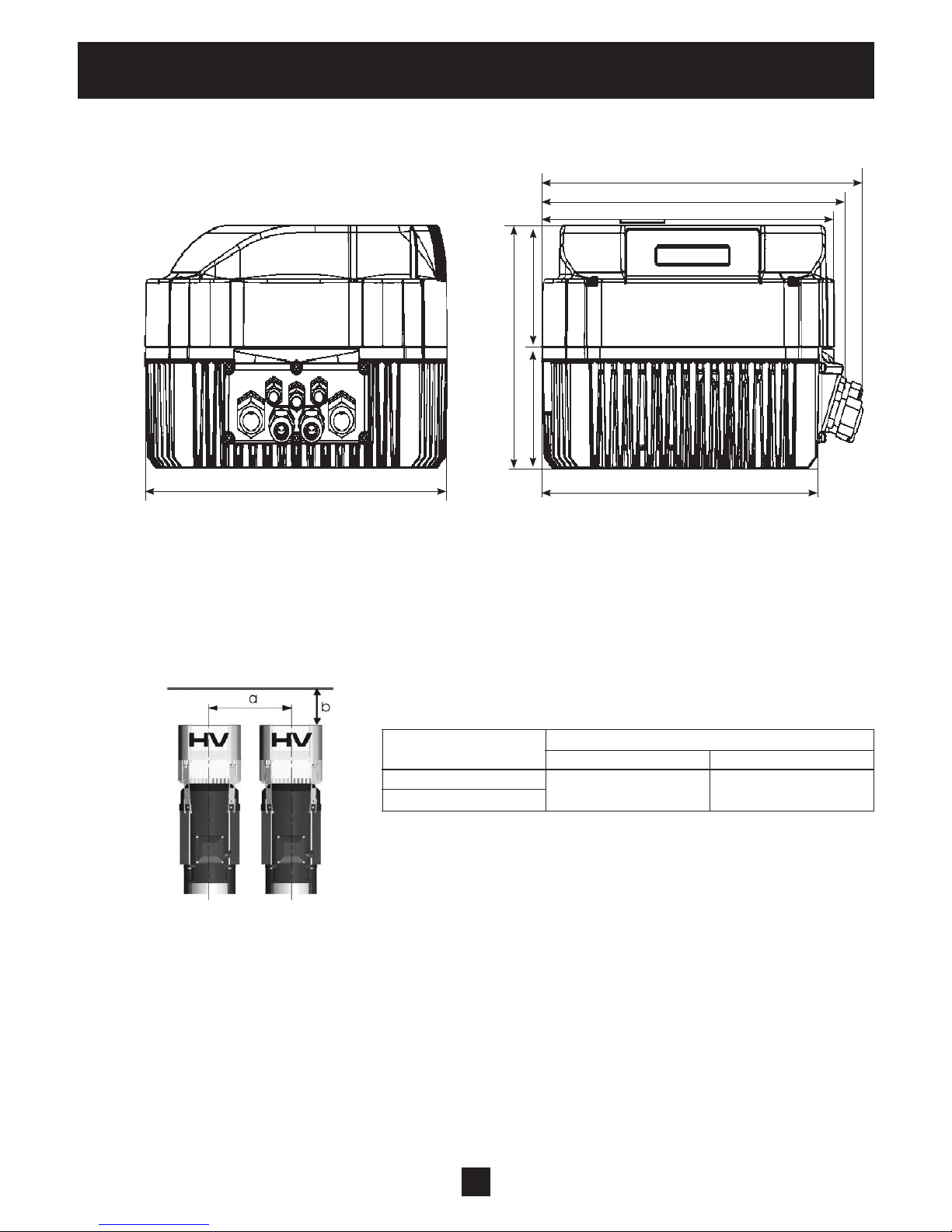
Dimensions and Weights
Section 6
HVM1202, HVM1203, HVM3403, 3405
8.9
8.2
7.9
3.353.35
6.7
7.9
7.4
All dimensions in inches! Drawings are not to scale!
Dimensions are nominal
Basic Master / Single
Weight [lbs]
Type
2, 3 HP
1 Ph
3, 5 HP
3 Ph
8.8 9.7
a … minimum center-distance between HYDROVARs 12"
b … header space for maintenance 12"
15
Dimensions and Weights
HVM3407, HVM3410, HVM3415
10.9
10.2
9.9
3.35
6.7
3.35
10.2
9.4
All dimensions in inches! Drawings are not to scale!
Dimensions are nominal
Basic Master / Single
7.5, 10, 15 HP
3 Ph
Weight [lbs]
Type
16.9 17.8
a … minimum centre-distance between HYDROVARs 17"
b … minimum header space for maintenance 12"
16

Additional Components
Section 7
7.1 Cable Glands Provided
Included Cable gland Conduit plugs Thermistor Mounting Centring components and lock nut clamps bit
12 16 20 25 12 16
Cable
size #8-#1 4,5-10 7-1 3 9-17
AWG
2.015- 2.022 2 (3) 2 2 3 1 1 4 1
4.022- 4.040 2 (3) 2 2 3 1 1 4 1
4.055- 4.110 2 (3) 2 2 3 1 1 4 1
Gland sizer
( ) maximum available cable entries
M M M M M M
7.2 Assembly Instructions – All models
To remove the HYDROVAR cover, loosen the 4 fastening screws.
• Verify that there is no liquid on the unit before you open the cover.
• The HYDROVAR is installed on the motor fan cover using the mounting brackets, the four screws and the
relevant washers.
• Center the HYDROVAR and tighten the four screws holding the brackets.
• Tighten each screw until the two bottom teeth in the brackets start to grip the fan cover.
• After the electrical components are connected, the top cover of the HYDROVAR can be mounted and
tightened by the four fastening screws.
• Ensure the integrity of the ground wire connection. Failure to properly ground the controller or motor
will create an electrical shock hazard.
• Ensure HYDROVAR cover gasket is in place before tightening the cover screws.
• Ensure cable glands are properly installed and close conduit openings that are not being used with
conduit plugs.
17

Additional Components
7.2 Assembly Instructions – All models (continued)
18
Electrical Installation and Wiring
Section 8
Note
All installations and maintenance must be performed by properly trained and
qualified personnel. Use personal protection equipment.
Note
In case of a failure, the electrical power must be disconnected or switched off. Wait
at least 5 minutes for capacitor discharge before servicing the HYDROVAR. Shock,
burns or death are possible hazards if the capacitor discharges during maintenance,
repair, or assembly.
8.1 Equipment Protection
Follow state, and local codes for proper equipment protection.
Applicable: • proper grounding
• AC and DC Ground Fault Circuit Interrupter (GFCI)
Proper grounding:
• Please note that leakage to ground can occur due to the capacitors in the input lter.
• A suitable protection unit has to be selected (according local regulations).
Ground Fault Circuit Interrupter (GFCI):
• When using a GFCI, make sure that it also releases in the event of a short circuit inside the DC-part of
the HYDROVAR to ground!
• single phase HYDROVAR => use pulse sensitive GFCI's
• three phase HYDROVAR => use AC/DC sensitive GFCI's
• The GFCI should be installed according to local regulations!
Fuses:
• Use Very fast acting Class T fuses
• Bussman T-tron type JJN and JJS fuses are acceptable (or equal)
Internal equipment protection:
• The Hydrovar has internal protections against the following malfunctions: short circuit; under and over-
voltage, overload and the overheating of the electronic components.
External protective devices:
• Additional protective functions like motor overheat and low water protection are controlled by separate
equipment.
19

Electrical Installation and Wiring
Fused Disconnect Box:
SINGLE
PHASE
CUSTOMER SUPPLIED
VOLTAGE
THREE
PHASE
CUSTOMER SUPPLIED
VOLTAGE
DISCONNECT
L1
L2
L1
L2
L3
1
3
5
GND
DISCONNECT
1
3
5
GND
2
4
6
2
4
6
12 AWG
12 AWG
12 AWG
12 AWG
12 AWG
FUSE BLOCK
FUSE BLOCK
CUSTOMER SUPPLIED
HYDROVAR
U1
U2
V1
V2
W1
W2
16 AWG
GND
PE
CUSTOMER SUPPLIED
HYDROVAR
U1
U2
V1
V2
W1
W2
16 AWG
GND
PE
MTR
MOTOR
GND
MTR
MOTOR
GND
ITT
Disconnect
Part Number
Input
Voltage
Disconnect
HP / AMP Wire Tightening Fuse AMP Part Voltage
Rating Range Torque Supplier Rating Number Rating
HFD512C1 230/1/60 OT25F3 2 HP / 25A #18-8AWG 7 IN/LB Bussman 20 KTK-R-20 600V
HFD512E1 230/1/60 OT40F3 3 HP / 40A #18-8AWG 7 IN/LB Bussman 30 KTK-R-30 600V
HFD534A1 460/3/60 OT16F3 3 HP / 16A #18-8AWG 7 IN/LB Bussman 10 KTK-R-10 600V
HFD534B1 460/3/60 OT16F3 3 HP / 16A #18-8AWG 7 IN/LB Bussman 15 KTK-R-15 600V
HFD534C1 460/3/60 OT25F3 3 HP / 25A #18-8AWG 7 IN/LB Bussman 20 KTK-R-20 600V
HFD534C2 460/3/60 OT25F3 3 HP / 25A #18-8AWG 7 IN/LB Bussman 20 KTK-R-20 600V
HFD534E2 460/3/60 OT40F3 3 HP / 40A #18-8AWG 7 IN/LB Bussman 30 KTK-R-30 600V
NOTE: Recommended protection (not included with drive only). This fused disconnect is available as part of the PHV series
packaged Hydrovar, see price book.
20

Electrical Installation and Wiring
8.2 EMC – Electromagnetic Compatibility
To ensure electromagnetic compatibility the following points must be observed for cable installation:
Control Cables
General Recommendations
Use shielded cables, temperature rated at 60º C (140º F) or above:
• Control cables must be multi-core cables with a braided copper wire screen.
Double Shielded Single Shielded
Example: JAMAK by Draka NK Cables Example: NOMAK by Draka NK Cables
• The screen must be twisted together into a bundle not longer than ve times its width and con-
nected to terminal X1-1 (for digital and analog I/O cables) or to either X1-28 or X1-32 (for RS485
cables).
Route control cables to minimize radiation to the cable:
• Route as far away as possible from the input power and motor cables (at least 20 cm (8 in)).
• Where control cables must cross power cables make sure they are at an angle as near 90º as
possible.
• Stay at least 20 cm (8 in) from the sides of the drive.
Use care in mixing signal types on the same cable:
• Do not mix analog and digital input signals on the same cable.
• Run relay-controlled signals as twisted pairs (especially if voltage > 48 V). Relay-controlled sig-
nals using less than 48 V can be run in the same cables as digital input signals.
NOTE! Never mix 24 VDC and AC power signals in the same cable.
Motor Wires
To ensure the EMC compatibility and minimize noise level and leakage currents, use the shortest possible motor wires. Use shielded wires only if the total length exceeds 6 feet.)
Line Reactors
Line reactors are available as an option and should be mounted between the HYDROVAR and the main
fuse. The Line reactor should be as close to the HYDROVAR as possible, (max. 12").
Advantages:
• more efcient
• reduction of harmonic currents
21

Electrical Installation and Wiring
For the following applications additional line reactors are strongly recommended:
• high short circuit currents
• compensation-plants without a coil
• asynchronous motors which are responsible for a voltage drop >20% of the line voltage
EMC Summary
• Install proper grounds according to local codes and regulations
• Do not install the power wires in parallel to control wires
• Use screened control cables
• Connect both ends of the motor wire screen to ground
• Connect only one end of the control wire screen to ground
• Motor wires should be as short as possible
8.3 Recommended Wire Types
For maximum 40º C ambient temperature, recommend use of 75º C wire of the following types: RHW,
THHW, THW, THWN, XHHW, USE, ZW.
8.4 Wiring and Connections
Remove the screws holding the top cover of the HYDROVAR.
Lift off the top cover. The following parts can be seen on a HYDROVAR Master / Single Drive:
1 Ph 2, 3 HP 3 Ph 3, 5 HP 3 Ph 7.5, 10, 15 HP
(A) Power supply (B) Motor connections (C) Terminal block:
- START/STOP
(D) RS-485 Interface (E) Status-Relays - SOLORUN (hand mode)
- User interface - RS-485 Interface
- Internal interface (F) Optional Relay Card
22

Electrical Installation and Wiring
8.4.1 Input Voltage Terminals
The power supply is connected to the power section:
Terminal L + N (230 VAC, single-phase)
Terminal L1+ L2 + L3 (460 VAC, three-phase)
2, 3 HP / 1Ø 3, 5 HP / 3Ø
7.5, 10, 15 HP / 3Ø
23

Electrical Installation and Wiring
8.4.2 Motor Connection
Attaching the Thermistor
Method A : Method B :
1. Remove conduit box cover
2. Attach the thermistor (Method A or B)
3. Replace the terminal block, if necessary
4. Wire the motor according to the motor manufacturer's instructions.
NOTE! The thermistor must be attached to the motor. This is required to measure
the motor temperature!
8.4.3 Power Unit
The basic drive has two control terminal blocks.
HVB 1202, 1203
HVB 3403, 3405
HVB 3407, 3410, 3415
24
 Loading...