

ITT Goulds Pumps 3298 Series, Goulds Pumps SP 3298, Goulds Pumps V 3298 Installation, Operation And Maintenance Instructions

Installation, Operation and Maintenance Instructions
3298
Frame Mounted
V 3298
3298
Close Coupled
3298 Family
SP 3298
Close Coupled

Pump Safety Tips
Safety Apparel:
Insulated work gloves when handling
·
hot bearings or using bearing heater
Heavy work gloves when handling
·
parts with sharp edges, especially impellers
Safety glasses (with side shields) for
·
eye protection, especially in machine
shop areas
Steel-toed shoes for foot protection when
·
handling parts, heavy tools, etc.
Other personal protective equipment to protect against
·
hazardous/toxic fluids
Coupling Guards:
Never operate a pump without a coupling guard properly
·
installed
Flanged Connections:
· Never force piping to make a connection with a pump
· Use only fasteners of the proper size and material
Operation:
Do not operate below minimum rated flow, or with
suction/discharge valves closed
Do not open vent or drain valves, or remove plugs while
system is pressurized
Maintenance Safety:
Always lockout power
·
Ensure pump is isolated from system and pressure is
·
relieved before disassembling pump, removing plugs, or
disconnecting piping
Use proper lifting and supporting equipment to prevent
·
serious injury
Observe proper decontamination procedures
·
Know and follow company safety regulations
·
· Never apply heat to remove impeller
· Observe all cautions and warnings highlighted in pump
Installation, Operation and Maintenance Instructions.
· Ensure there are no missing fasteners
· Beware of corroded or loose fasteners

IMPORTANT SAFETY REMINDER
To: Our Valued Customers
Goulds' pumps will provide safe, trouble-free service when properly installed, maintained, and operated. We have an
extensive network of experienced sales and service professionals to assist in maximizing your satisfaction with our products.
Safe installation, operation, and maintenance of Goulds' equipment are an essential end user responsibility. This Instruction,
Operation, and Maintenance (IOM) manual identifies specific safety risks that must be considered at all times during product
life. Understanding and adhering to these safety warnings is mandatory to ensure person- nel, property, and/or the environment
will not be harmed. Adherence to these warnings alone, however, is not sufficient — it is anticipated that the end user will also
comply with industry and corporate safety standards. Identifying and eliminating unsafe installation, operating and maintenance
practices is the responsibility of all individuals involved in the installation, operation, and maintenance of industrial equipment.
Specific to pumping equipment, two significant risks bear reinforcement above and beyond normal safety precautions.
! WARNING
▲
Operation of any pumping system with a blocked suction and discharge must be avoided in all cases. Operation, even
for a brief period under these conditions, can cause superheating of enclosed pumpage and result in a violent
1
explosion. All necessary measures must be taken by the end user to ensure this condition is avoided.
! WARNING
▲
Pumping equipment Instruction, Operation, and Maintenance manuals clearly identify accepted methods for
disassembling pumping units. These methods must be adhered to. Specifically, applying heat to impellers and/or
2
impeller retaining devices to aid in their removal is strictly forbidden. Trapped liquid can rapidly expand and result
in a violent explosion and injury.
Please take the time to review and understand the safe installation, operation, and maintenance guidelines outlined in this
manual.

FOREWORD
This manual provides instructions for the Installation, Operation, and Maintenance of the Goulds Model
3298 family of Magnetic Drive Process Pumps. This manual must be read and understood before
installation and start-up.
The design, materials, and workmanship incorporated in the construction of Goulds pumps makes them
capable of giving trouble-free service. The life and satisfactory service of any mechanical unit, however,
is enhanced and extended by correct application, proper installation, periodic inspection, condition
monitoring and careful maintenance. This instruction manual was prepared to assist operators in
understanding the construction and the correct methods of installing, operating, and maintaining these
pumps.
ITT Industries - Goulds shall not be liable for physical injury, damage or delays caused by a failure to
observe the instructions for Installation, Operation, and Maintenance contained in this manual.
Warranty is valid only when genuine ITT Industries - Goulds Pumps parts are used.
Use of the equipment on a service other than stated in the order could nullify the warranty, unless
written approval is obtained in advance from ITT Industries, Goulds Pumps.
Supervision by an authorized ITT Industries - Goulds representative is recommended to assure proper
installation.
Additional manuals can be obtained by contacting your local ITT Industries - Goulds representative, by
calling 1-800-446-8537, or visiting our website at www.gouldspumps.com.
THIS MANUAL EXPLAINS
Proper Installation
n
Start-Up Procedures
n
Operation Procedures
n
Routine Maintenance
n
Pump Overhaul
n
Troubleshooting
n
Ordering Spare or Repair Parts
n
4 3298 Family Rev. 4/07

TABLE OF CONTENTS
PAGE
7 SAFETY
11 GENERAL INFORMATION
15 INSTALLATION
27 OPERATION
33 PREVENTIVE MAINTENANCE
39 DISASSEMBLY & REASSEMBLY
SECTION
1
2
3
4
5
6
113 SPARE AND REPAIR PARTS
125 APPENDICES
I Hydraulic Coverage Charts
II Coupling Guard Installation
III Impeller Trim Procedures
IV Power Monitors
V Reliability Tips for Operating Lined Magnetically-Driven
Sealless Pumps (Quick Reference Guide
VI Polyshield®ANSI Combo Installation, Operation and
Maintenance Instructions
7
8
3298 Family Rev. 4/07 5

6 3298 Family Rev. 4/07

SAFETY
DEFINITIONS ................................7
MEDICAL PRECAUTIONS ........................8
GENERAL PRECAUTIONS ........................8
DEFINITIONS
1
These pumps have been designed for safe and reliable
operation when properly used and maintained in
accordance with instructions contained in this manual. A
pump is a pressure containing device with rotating parts
that can be hazardous. Operators and maintenance
personnel must realize this and follow safety measures.
ITT Industries Goulds Pumps shall not be liable for
physical injury, damage or delays caused by a failure to
observe the instructions in this manual.
Throughout this manual the words WARNING,
CAUTION, ELECTRICAL, ATEX, and NOTE are used
to indicate procedures or situations which require special
operator attention:
! WARNING
s
Operating procedure, practice, etc. which, if not
correctly followed, could result in personal injury or
loss of life.
! CAUTION
$
Operating procedure, practice, etc. which, if not
followed, could result in damage or destruction of
equipment.
Particular care must be taken when electrical power
"
source to the equipment is energized.
EXAMPLES
! WARNING
s
Pump shall never be operated without coupling guard
installed correctly.
! CAUTION
$
Throttling flow from the suction side may cause
cavitation and pump damage.
Improper impeller adjustment could cause contact
!
between the rotating and stationary parts, resulting
in a spark and heat generation.
Lock out driver power to prevent electric shock,
!
accidental start-up, and physical injury.
Lock out driver power to prevent electric shock,
"
accidental start-up and physical injury.
NOTE: Proper alignment is essential for long pump life.
If equipment is to be installed in a potentially
!
explosive atmosphere and these procedures are not
followed, personal injury or equipment damage from
an explosion may result.
NOTE: Operating procedure, condition, etc. which is
essential to observe.
3298 Family Rev. 4/07 7

MEDICAL PRECAUTIONS
! WARNING
s
Magnetic drive pumps contain very strong magnets
which may pose health risks. The following guidelines
shall always be observed.
1. When disassembled and magnets are exposed,
individuals with artificial cardiac pacemakers,
implanted defibrillators, metallic prosthetic heart
valves, internal wound clips (from surgery), prosthetic
joints, metallic wiring, or other metallic prosthetic
devices shall avoid working with, being in proximity
of, or handling the magnets contained in the pumps.
GENERAL PRECAUTIONS
! WARNING
s
Personal injuries will result if procedures outlined in
this manual are not followed.
NEVER use heat to disassemble pump due to risk of
C
explosion from trapped liquid.
NEVER operate pump without coupling guard
AC
AD
AD
correctly installed.
NEVER operate pump beyond the rated conditions
to which the pump was sold.
NEVER start pump without proper prime (all
models), or proper liquid level in self-priming
pumps (Model SP3298).
2. When disassembled and magnets are exposed,
individuals who have had previous surgeries (especially
chest or head surgery) and who do not know if they have
metallic clips internally should avoid work on this unit
unless it can be established by his or her physician that no
risk exists while working on a magnet drive pump.
NEVER run pump below recommended minimum
A C
C
AC
AD
AC
flow or when dry.
ALWAYS lock out power to the driver before
B
performing pump maintenance.
NEVER operate pump without safety devices
C
installed.
NEVER operate pump with discharge valve closed.
NEVER operate pump with suction valve closed.
DO NOT change conditions of service without
approval of an authorized ITT-Goulds representative.
EXPLOSION PREVENTION
In order to reduce the possibility of accidental explosions in atmospheres containing explosive gases and/or dust, the
!
instructions under the ATEX symbol must be closely followed. ATEX certification is a specification enforced in
Europe for non-electrical and electrical equipment installed in Europe. The usefulness of the ATEX requirements is
not limited to Europe. They are useful guidelines for equipment installed in any potentially explosive environment.
NOTE: When pumping unit is installed in a potentially explosive atmosphere, the instructions after the Ex symbol
!
must be followed. Personal injury and/or equipment damage may occur if these instructions are not followed. If
there is any question regarding these requirements or if the equipment is to be modified, please contact a Goulds
representative before proceeding.
8 3298 Family Rev. 4/07

SPECIAL ATEX CONSIDERATIONS
All installation and operation instructions in this manual
must be strictly adhered to. In addition, care must be taken
to ensure that the equipment is properly maintained. This
includes but is not limited to:
1. Monitoring the pump frame and liquid end temperature.
ATEX IDENTIFICATION
For a pumping unit (pump, seal, coupling, motor and pump
accessories) to be certified for use in an ATEX classified
environment, the proper ATEX identification must be
present.
The ATEX tag would be secured to the pump or the
baseplate on which it is mounted. A typical tag would look
like this:
The CE and the Ex designate the ATEX compliance. The
code directly below these symbols reads as follows:
=
II
2=
G/D =
Tx =
Group 2
Category 2
Gas and Dust present
Temperature class, can be T1 to T4
(see Table 1)
2. Maintaining proper bearing lubrication.
3. Ensuring that the pump is operated in the intended
hydraulic range.
Table 1
Max
Max
permissible surface
temperature
Code
T1 842 (450) 700 (372)
T2 572 (300) 530 (277)
T3 392 (200) 350 (177)
T4 275 (135) 235 (113)
T5 212 (100)
T6 185 (85)
The code classification marked on the equipment should be
in accordance with the specified area where the equipment
will be installed. If it is not, please contact your
ITT/Goulds representative before proceeding.
o
F(oC)
permissible
liquid
temperature
o
F(oC)
Option not
available
Option not
available
2
INTENDED USE
The ATEX conformance is only applicable when the pump
unit is operated within its intended use. All instructions
within this manual must be followed at all times. Operating, installing or maintaining the pump unit in any way that
is not covered in this manual can cause serious personal
injury or damage to the equipment. This includes
3298 Family Rev. 4/07 9
any modification to the equipment or use of parts not
provided by ITT/Goulds. If there is any question regarding
the intended use of the equipment, please contact an
ITT/Goulds representative before proceeding.

CONDITION MONITORING
For additional safety precautions, and where noted
!
in this manual, condition monitoring devices should
be used. If applicable, devices should comply with
ATEX. This includes, but is not limited to:
Pressure gauges
u
Flow meters
u
Level indicators
u
Motor load readings
u
Temperature detectors
u
Bearing monitors
u
Leak detectors
u
PumpSmart
u
®
control system
For assistance in selecting the proper instrumentation and
its use, please contact your ITT/Goulds representative.
10 3298 Family Rev. 4/07

GENERAL INFORMATION
PUMP DESCRIPTION ...........................11
NAMEPLATE INFORMATION .....................12
RECEIVING THE PUMP .........................13
Storage Requirements ..........................13
Handling .................................13
PUMP DESCRIPTION
2
The Model 3298 is a sealless close coupled or frame
mounted centrifugal pump with an enclosed impeller that is
driven by a synchronous magnetic coupling and meets
1
dimensional standards of ANSI B73.1. (The 1x1
-5 is not
2
ANSI dimensional.)
The SP 3298 is a self-priming sealless close coupled or
frame mounted centrifugal pump with an enclosed impeller
that is driven by a synchronous magnetic coupling. The
pump and frame / adapter feet locations meet ANSI B73.1
dimensional standards.
The V 3298 is a vertical in-line sealless close coupled
centrifugal pump with an enclosed impeller that is driven
by a synchronous magnetic coupling and meets the
dimensional standards of ANSI B73.2.
Casing - The casings are one piece cast ductile iron lined
with 1/8" TEFZEL
a TEFZEL
®
®1
and have ANSI class 150 flanges with
raised face. The 3298 and SP 3298 are end
suction, top centerline discharge and are self-venting. The
V 3298 is side suction, side discharge and is also
self-venting.
Impeller Magnet Assembly - The 3298 family utilizes a
one or two piece impeller magnet assembly. The magnet
ring is balanced to ISO 1940 G6.3 levels and is sealed
within the solid enclosed TEFZEL
®
impeller magnet
assembly.
Stationary Shaft - The impeller magnet assembly rotates
about a solid stationary silicon carbide shaft. The shaft is
supported at one end by the containment shell and the other
end by the TEFZEL
®
bearing spider.
Rear Impeller Wear Ring - is standard on M and L group
size pumps and is not required on S group sizes. The wear
ring is pressed into the rear of the impeller assembly. The
wear ring reduces axial thrust in the M and L group size
pumps.
Magnetic Coupling - is a coaxial synchronous type using
rare earth magnets. This concept results in a compact
design and allows the impeller to turn at the same speed as
the motor, (i.e. there is no slip between the drive and driven
magnets.)
Magnets - Neodymium Iron (NdFe).
Containment Shell - isolates the pumped liquid from the
atmosphere. The containment shell construction is backed
with vinylester FRP.
Radial Bearings and Thrust Bearings - Goulds standard
bearing material is carbon with optional Pure Sintered
Alpha Grade Silicon Carbide or DryGuard™ Pure Sintered
Alpha Grade Silicon Carbide.
Standard Close Coupled Mounting - The drive magnet
assembly is keyed, set screwed and mounted directly to the
motor shaft. This arrangement eliminates the need to
perform pump/motor alignment.
Optional Power End
3
- The standard configuration is cast
iron with flood oil lubricated ball bearings. Pure oil mist
systems are available as an option. For protection and
reliability of the bearings and the lubricant, a labyrinth seal
is provided. On the inboard side a lip seal is used to prevent
leakage of oil into the magnetic drive assembly.
Bearing Spider - The bearing spider constructed from
solid TEFZEL
®
houses one of the key silicon carbide thrust
bearings in the pump and supports the stationary shaft at
one end.
1
TEFLON®and TEFZEL®: Registered trademarks for fluoropolymer resins, films and fibers made by DuPont.
2
The 1x1
3
Frame mounted power end not available on the V 3298.
3298 Family Rev. 4/07 11
1
-5 is tangential discharge.
2

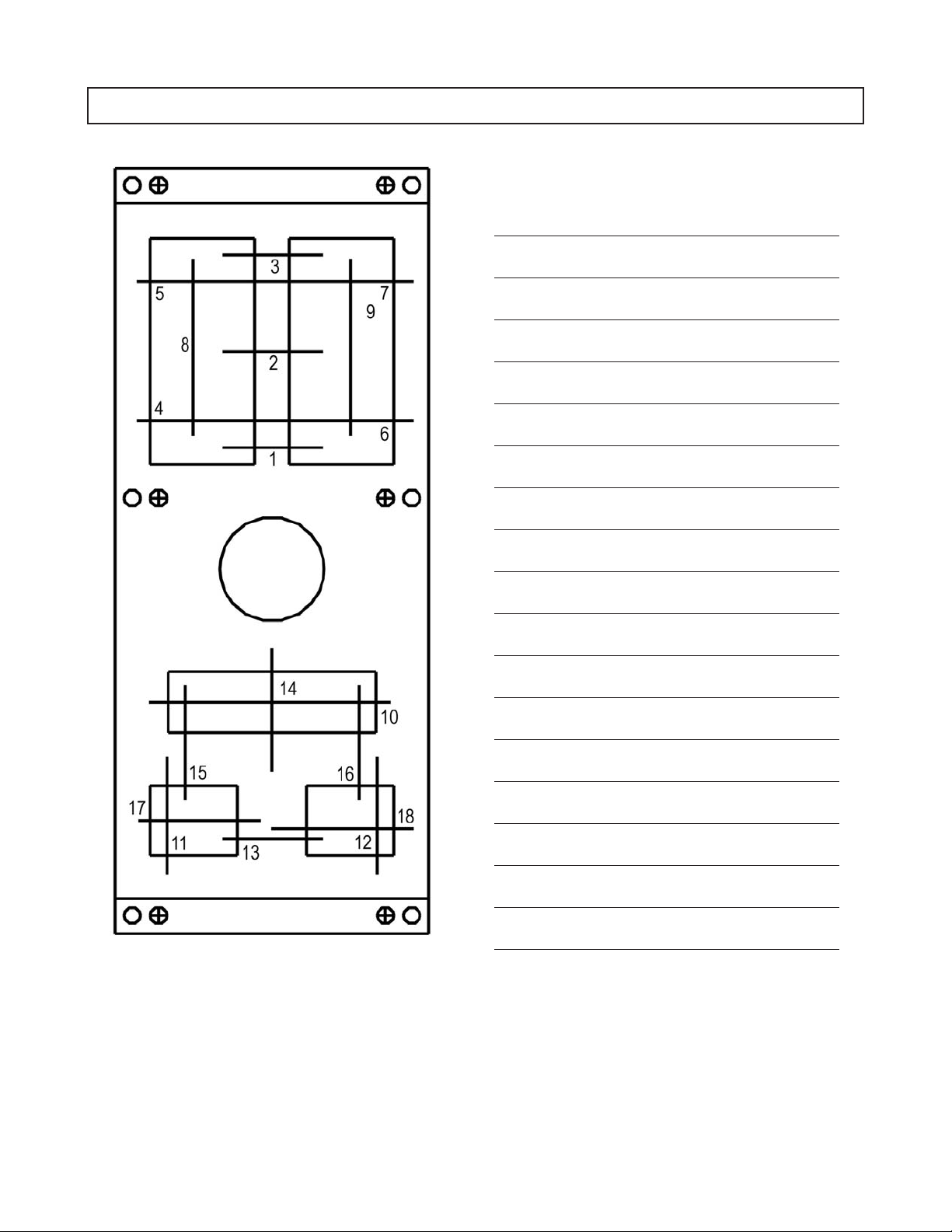
NAMEPLATE INFORMATION
Every pump has two Goulds nameplates that provide
information about the pump. The tags are located on the
casing and bearing frame.
Fig.
Description
Pump Casing Tag - provides information about
the pump’s hydraulic characteristics.
Note the format of the pump size:
Discharge x Suction - Nominal maximum
Impeller Diameter in inches
(Example: 2x3-8)
No. Example
Fig. 1
English
When ordering spare parts, you will need to identify pump
model, size, serial number, and the item number of required
parts. Information can be taken from the pump casing tag.
Item numbers can be found in this manual
(Figs.1&2).
Bearing Frame Tag - provides information on
the lubrication system used (Fig. 3).
ATEX Tag - If applicable, your pump unit may
have the following ATEX tag affixed to the
pump and/or baseplate. See the Safety section for
a description of the symbols and codes (Fig. 4).
Fig. 2
Metric
Fig. 3
Fig. 4
12 3298 Family Rev. 4/07

RECEIVING THE PUMP
Inspect the pump as soon as it is received. Make notes of
damaged or missing items on the receipt and freight bill.
File any claims with the transportation company
immediately.
STORAGE REQUIREMENTS
Short Term - (Less than 3 months) Goulds normal
packaging procedure is designed to protect the pump
during shipping. Upon receipt store in a covered and dry
location.
Long Term - (More than 6 months) Preservative treatment
of bearings and machined surfaces will be required. Rotate
shaft several times every 3 months. Refer to driver and
coupling manuals for their long term storage procedures.
Store in a dry covered location.
HANDLING
! WARNING
s
Failure to properly lift and support equipment could
result in serious injury or damage to pumps.
Use care when moving pumps. Lifting equipment must be
able to adequately support the entire assembly. Hoist bare
pumps, using a sling under the suction flange and bearing
housing. (Fig. 5)
Baseplate mounted units are moved with slings under the
pump and driver. (Figs.5&7)
2
Fig. 6
! WARNING
s
These pumps use ceramic silicon carbide components.
Do not drop pump or subject to shock loads, this may
damage internal ceramic components.
Fig. 5
Fig. 7
3298 Family Rev. 4/07 13

Complete vertical pumps are lifted with straps under the
pump and motor (Fig. 8). Bare vertical pumps (without a
motor) are lifted with straps under the pump and motor
adapter (Fig. 9).
Fig. 8
Fig. 9
14 3298 Family Rev. 4/07

INSTALLATION
BASEPLATE INSPECTION........................15
SITE/FOUNDATION............................15
LEVEL BASEPLATE ...........................16
Cast Iron/Fabricated Steel ........................16
Feature Fabricated Steel/API Style....................17
Baseplate Leveling Worksheet ......................18
ALIGNMENT AND ALIGNMENT PROCEDURE ...........19
Alignment Checks ............................19
Alignment Criteria ............................19
SetUp...................................20
Measurement ...............................20
Angular Alignment ............................20
Parallel Alignment ............................21
Complete Alignment ...........................21
Alignment Troubleshooting .......................22
GROUT BASEPLATE ...........................22
PIPING....................................23
General ..................................23
Suction Piping ..............................23
Discharge Piping .............................25
Final Piping Check ............................25
3
Equipment that is to be installed in a potentially explosive environment must be done so in accordance with the
!
following installation instructions.
BASEPLATE INSPECTION
1. Remove all equipment.
2. Completely clean the underside of baseplate. It is
sometimes necessary to coat the underside of the
baseplate with an epoxy. This may have been
purchased as an option.
3. Remove the rust preventative solution from the
machined pads with an appropriate solution.
SITE / FOUNDATION
A pump should be located near the supply of liquid and
have adequate space for operation, maintenance, and
inspection.
Baseplate mounted pumps are normally grouted to a
concrete foundation, which has been poured on a solid
footing. The foundation must be able to
absorb any vibration and to form a permanent, rigid
support for the pumping unit.
The location and size of the foundation bolts are shown on
the outline assembly drawing, provided with the pump data
package.
3298 Family Rev. 4/07 15

All equipment being installed must be properly
!
grounded to prevent unexpected static electric
discharge. This includes ensuring that the PFA
lined pumps are pumping fluids that are conductive.
If not, a static electric discharge may occur when the
pump is drained and disassembled for maintenance
purposes.
Foundation bolts commonly used are sleeve type (Fig. 10)
and J type (Fig. 11). Both designs permit movement for
final bolt adjustment.
1. Inspect foundation for dust, dirt, oil, chips, water, etc.
and remove any contaminants. Do not use oil-based
cleaners as grout will not bond to it.
2. Prepare the foundation in accordance with the grout
manufacturer’s recommendations.
Fig. 10
Fig. 11
LEVEL BASEPLATE
CAST IRON / FABRICATED STEEL
1. Place two sets of wedges or shims on the foundation,
one set on each side of every foundation bolt
(Fig. 12, 13). The wedges should extend .75 in.
(20 mm) to 1.5 in. (40 mm) above the foundation, to
allow for adequate grouting. This will provide even
support for the baseplate once it is grouted.
2. Remove water and/or debris from anchor bolt
holes/sleeves. If the sleeve type bolts are being used,
fill the sleeves with rags to prevent grout from
entering.
3. Carefully lower baseplate onto foundation bolts.
4. Level baseplate to within .125 in.(3mm) over the length of
the base and .062 in. (1.5 mm) over the width of the base by
adjusting shims or wedges.
5. Hand tighten bolts.
Fig. 13
Fig. 12
16 3298 Family Rev. 4/07

FEATURE FABRICATED STEEL/
API STYLE
(BASEPLATES PROVIDED WITH VERTICAL
LEVELING ADJUSTORS)
1. Coat the jack screws with an anti-seizing compound to
allow for easy removal after the grout has been cured.
2. Cut round circular plates from bar stock to set the jack
screws on. The edges of the plates should be
chamfered to reduce stress concentrations.
3. Set the baseplate on the foundation and use the four
corner jack screws to raise the baseplate off the
foundation 0.75" to 1.5" (Fig. 14). The two center jack
screws should not be touching the foundation.
Fig. 14
4. Place two machinist levels on the motor pads, one
lengthwise on a single motor pad, and another across the
ends of both motor pads (Fig 15).
NOTE: When using a machinist level, it is important
that the surface being leveled is free of all
contaminants, such as dust, to ensure an accurate
reading.
7. Place the two levels on the pump pads, one lengthwise
on a single pump pad, and another across the middle of
both pump pads. (Fig. 16)
Fig. 16
3
8. Level the pump pads as close to zero as possible, in
both directions, by adjusting the jack screws.
9. Install the anchor bolts until they are hand tight.
10. Return the levels to the motor pads and check the level
measurements.
11. Adjust the jack screws and anchor bolts, if necessary,
until all level measurements are within the design
requirements of 0.002 in./ft.
12. When taking readings, center the level over the pad
being measured.
NOTE: The Baseplate Leveling Worksheet provided
may be used when taking readings.
5. Level the motor pads as close to zero as possible, in
both directions, by adjusting the four jack screws.
6. Next, turn down the center jack screws so that they are
resting on their metal discs on the foundation.
Fig. 15
3298 Family Rev. 4/07 17
BASEPLATE LEVELING WORKSHEET
LEVEL MEASUREMENTS
1)
2)
3)
4)
5)
6)
7)
8)
9)
10)
11)
12)
13)
14)
15)
16)
17)
18)
18 3298 Family Rev. 4/07

ALIGNMENT AND ALIGNMENT PROCEDURE
! WARNING
B
s
Before beginning any alignment procedure, make sure
driver power is locked out. Failure to lock out driver
power can result in serious personal injury.
Alignment procedures must be followed to prevent
!
unintended contact of rotating parts. Follow
coupling manufacturer's coupling installation and
operation procedures.
To remove guard, refer to coupling guard assembly/
disassembly instructions.
The points at which alignment is checked and adjusted are:
Initial Alignment is done prior to operation when
·
the pump and the driver are at ambient temperature.
Final Alignment is done after operation when the
·
pump and driver are at operating temperature.
Alignment is achieved by adding or removing shims from
under the feet of the driver and shifting equipment
horizontally as needed.
NOTE: Proper alignment is the responsibility of the
installer of the unit.
Accurate alignment of the equipment must be attained.
Trouble-free operation can be accomplished by following
these procedures:
ALIGNMENT CHECKS
Initial Alignment (Cold Alignment)
Before Grouting Baseplate - To ensure alignment can be
·
obtained.
Final Alignment (Hot Alignment)
After First Run - To obtain correct alignment when both
·
pump and driver are at operating temperature.
Thereafter, alignment should be checked periodically in
accordance with plant operating and maintenance
procedures.
NOTE: Alignment check must be made if process
temperature changes, piping changes, and/or pump
service is performed.
ALIGNMENT CRITERIA
Good alignment is achieved when the dial indicator
readings as specified in the alignment procedure are .002
in. (.05 mm) Total Indicated Reading (T.I.R.) or less when
the pump and driver are at operating temperature (Final
Alignment).
During the installation phase, however, it is necessary to
set the parallel alignment in the vertical direction to a
different criteria due to differences in expansion rates of
the pump and driver. Table 2 below shows recommended
cold settings for electric motor driven pumps based on
different pumpage temperatures. Driver manufacturers
should be consulted for recommended cold settings for
other types of drivers (steam turbines, engines, etc.).
Table 2
Cold Settings of Parallel
Vertical Alignment
Pumpage
Temperature Set Driver Shaft
50°F (10°C) .002in. (.05mm) LOW
150°F (65°C) .001in. (.03mm) HIGH
250°F (120°C) .005in. (.12mm) HIGH
3
After Grouting Baseplate - To ensure no changes to
·
alignment have occurred during grouting process.
After Connecting Piping - To ensure that pipe strains
·
haven’t altered alignment. If changes have occurred,
alter piping to remove pipe strains on pump flanges.
3298 Family Rev. 4/07 19

SET UP
1. Mount two dial indicators on one of the coupling
halves (X) so they contact the other coupling half (Y)
(Fig. 17).
2. Check setting of indicators by rotating coupling half X
to ensure indicators stay in contact with coupling half
Y but do not bottom out. Adjust indicators
accordingly.
Fig. 17
MEASUREMENT
1. To ensure accuracy of indicator readings, always rotate
both coupling halves together so indicators contact the
same point on coupling half Y. This will eliminate any
measurement problems due to runout on coupling half
Y.
2. Take indicator measurements with driver feet hold
down bolts tightened. Loosen hold down bolts prior to
making alignment corrections.
3. Take care not to damage indicators when moving
driver during alignment corrections.
Fig. 18
4. Repeat steps 1 through 3 until indicator A reads .002
in (.05 mm) or less.
Horizontal Correction (Side to Side)
1. Zero indicator A on left side of coupling half Y, 90°
from top dead center (9 o’clock).
2. Rotate indicators through top dead center to the right
side, 180° from the start (3 o’clock). Observe needle
and record reading.
3. Negative Reading - The coupling halves are further
apart on the right side than the left. Correct by either
sliding the shaft end of the driver to the left or the
other end to the right.
Positive Reading - The coupling halves are closer
together on the right side than the left. Correct by
either sliding the shaft end of the driver to the right or
the other end to the left (Fig. 19).
4. Repeat steps 1 through 3 until indicator A reads .002
in. (.05 mm) or less.
ANGULAR ALIGNMENT
A unit is in angular alignment when indicator A (Angular
indicator) does not vary by more that .002 in. (.05 mm) as
measured at four locations 90° apart.
Vertical Correction (Top to Bottom)
1. Zero indicator A at top dead center (12 o’clock) of
coupling half Y.
2. Rotate indicators to bottom dead center
(6 o’clock). Observe needle and record reading.
3. Negative Reading - The coupling halves are further
apart at the bottom than at the top. Correct by either
raising the driver feet at the shaft end (add shims) or
lowering the driver feet at the other end (remove
shims) (Fig. 18).
Positive Reading - The coupling halves are closer at
the bottom than at the top. Correct by either lowering
the driver feet at the shaft end (remove shims) or
raising the driver feet at the other end (add shims).
5. Re-check both horizontal and vertical readings to
ensure adjustment of one did not disturb the other.
Correct as necessary.
20 3298 Family Rev. 4/07
Fig. 19

PARALLEL ALIGNMENT
A unit is in parallel alignment when indicator P (parallel
indicator) does not vary by more than .002 in. (.05 mm) as
measured at four points 90° apart at operating temperature.
Note the preliminary cold setting criteria, Table 2.
Vertical Correction (Top to Bottom)
1. Zero indicator P at top dead center of coupling
(12 o’clock) half Y (Fig. 19).
2. Rotate indicator to bottom dead center
(6 o’clock). Observe needle and record reading.
3. Negative Reading - Coupling half X is lower than
coupling half Y. Correct by removing shims of
thickness equal to half of the indicator reading under
each driver foot.
Positive Reading - Coupling half X is higher than
coupling half Y. Correct by adding shims of thickness
equal to half of the indicator reading from each driver
foot (Fig. 20).
Positive Reading - Coupling half Y is to the
right of coupling half X. Correct by sliding driver
evenly in the appropriate direction.
Fig. 21
3
NOTE: Failure to slide motor evenly will affect
horizontal angular correction.
4. Repeat steps 1 through 3 until indicator P reads .002
in. (.05 mm) or less.
5. Re-check both horizontal and vertical readings to
ensure adjustment of one did not disturb the other.
Correct as necessary.
Fig. 20
NOTE: Equal amounts of shims must be added to or
removed from each driver foot. Otherwise the vertical
angular alignment will be affected.
4. Repeat steps 1 through 3 until indicator P reads within
.002 in. (.05 mm) or less when hot, or per Table 1
when cold.
Horizontal Correction (Side to Side)
1. Zero indicator P on the left side of coupling half Y,
90° from top dead center (9 o’clock).
2. Rotate indicators through top dead center to the right
side, 180° from the start. Observe needle and record
reading (3 o’clock).
3. Negative Reading - Coupling half Y is to the left of
coupling half X. Correct by sliding driver evenly in the
appropriate direction (Fig. 21).
COMPLETE ALIGNMENT
A unit is in complete alignment when both indicators A
(angular) and P (parallel) do not vary by more than .002 in.
(.05 mm) as measured at four points 90° apart.
Vertical Correction (Top to Bottom)
1. Zero indicators A and P at top dead center
(12 o’clock) of coupling half Y.
2. Rotate indicator to bottom dead center (6 o’clock).
Observe the needles and record the readings.
3. Make corrections as outlined previously.
Horizontal Correction (Side to Side)
1. Zero indicators A and P on the left side of coupling
half Y, 90° from top dead center (9 o’clock).
2. Rotate indicators through top dead center to the right
side, 180° from the start (3 o’clock). Observe the
needle, measure and record the reading.
3. Make corrections as outlined previously.
4. Recheck both vertical and horizontal readings to
ensure adjustment of one did not disturb the other.
Correct as necessary.
3298 Family Rev. 4/07 21

ALIGNMENT TROUBLESHOOTING
Alignment Troubleshooting
PROBLEM PROBABLE CAUSE REMEDY
Cannot obtain horizontal (Side-to-Side)
alignment, angular or parallel.
Cannot obtain vertical (Top to Bottom)
alignment, angular or parallel.
NOTE: With experience, the installer will understand
the interaction between angular and parallel and will
make corrections appropriately.
Driver feet bolt bound.
Baseplate not leveled properly,
probably bowed.
GROUT BASEPLATE
Table 3
Loosen pump hold down bolts and slide pump and driver
until horizontal alignment is achieved.
Determine if center of baseplate should be raised or
lowered and correct by evenly adding or removing shims
at the center of the baseplate.
1. Clean areas of baseplate that will contact grout. Do not
use an oil-based cleaner because grout will not bond to it.
2. Build a dam around foundation (Fig. 22). Thoroughly
wet foundation.
3. Pour grout through grout hole in baseplate up to level of
dam. Remove air bubbles from grout as it is poured by
puddling, using a vibrator, or pumping the grout into
place. Non-shrink grout is recommended (Fig. 22).
Fig. 22
4. Allow grout to set.
5. Fill remainder of baseplate with grout. Remove air as
before (Fig. 23).
Fig. 23
6. Allow grout to set at least 48 hours.
7. Tighten foundation bolts.
ALIGNMENT CHECK
Re-check alignment before continuing, using methods
previously described.
22 3298 Family Rev. 4/07

PIPING
Guidelines for piping are given in the Centrifugal Pump
section of the “Hydraulic Institute Standards” and should
be reviewed prior to pump installation.
A
! WARNING
s
Never draw piping into place by forcing at the flanged
connections of the pump. This will impose dangerous
strains on the unit and cause misalignment between
pump and driver. Pipe strain can adversely effect the
operation of the pump. That could result in serious
personal injury and damage to equipment.
Flange loads from the piping system, including
!
those from thermal expansion of the piping, must
not exceed the limits of the pump. Casing deformation can result in contact with rotating parts and
result in excess heat generation, sparks and
premature failure.
1. All piping must be supported independently and must
line up naturally with the pump flanges.
2. Piping runs shall be designed to minimize friction
losses.
3. DO NOT make final connection of piping to pump
until grout has hardened and pump and driver
hold-down bolts have been tightened.
4. It is suggested that expansion loops or joints, if used,
be properly installed in suction and/or discharge lines
when handling liquids at elevated temperatures, so
linear expansion of piping will not draw pump out of
alignment (Fig. 24 & 25).
Fig. 25
5. The piping should be arranged to allow pump flushing
prior to removal of the unit on services handling
corrosive liquids.
6. System should be thoroughly cleaned prior to
installation.
SUCTION PIPING
A
! WARNING
s
NPSHAmust always exceed NPSHRas shown on
Goulds performance curves received with order.
Reference Hydraulic Institute for NPSH and pipe
friction values needed to evaluate suction piping.
Properly installed suction piping is a necessity for trouble
free pump operation. Suction piping should be flushed
BEFORE connection to the pump.
3
1. Use of elbows close to the pump suction flange should
be avoided. There should be a minimum of 2 pipe
diameters of straight pipe between the elbow and
suction inlet. Where used, elbows should be long
radius (Fig. 26)
Fig. 24
3298 Family Rev. 4/07 23

CORRECT
CORRECT PIPING
Fig. 26
Fig. 28
Suction Lift Conditions
1. Suction pipe must be free from air pockets
Fig. 27
2. Use suction pipe one or two sizes larger than the pump
suction, with a reducer at the suction flange. Suction
piping should never be of smaller diameter than the
pump suction.
3. Reducers should be eccentric at the pump suction
flange with sloping side down and horizontal side at
the top (Figs. 26, 27, 28).
$
Pump must never be throttled on suction side.
4. Suction strainers, when used, must have a net “free
area” of at least three times the suction pipe area.
5. Separate suction lines are recommended when more
than one pump is operating from the same source of
supply.
CAUTION
2. Suction piping must slope upwards to pump.
3. All joints must be air tight.
4. A means of priming the pump must be provided, such
as a foot valve, except for the self priming pump.
Suction Head/Flooded Suction Conditions
1. An isolation valve should be installed in the suction
line at least two pipe diameters from the suction to
permit closing of the line for pump inspection and
maintenance.
2. Keep suction pipe free from air pockets.
3. Piping should be level or slope gradually downward
from the source of supply
4. No portion of the piping should extend below pump
suction flnge.
5. The size of entrance from supply should be one or two
sizes larger than the suction pipe.
6. The suction pipe must be adequately submerged below
the liquid surface to prevent vortices and air
entrainment at the supply.
24 3298 Family Rev. 4/07

INCORRECT PIPING
DISCHARGE PIPING
1. Isolation and check valves should be installed in
discharge line. Locate the check valve between
isolation valve and pump, this will permit inspection of
the check valve. The isolation valve is required for
priming, regulation of flow, and for inspection and
maintenance of pump. The check valve prevents pump
or seal damage due to reverse flow through the pump
when the driver is turned off.
2. Increasers, if used, should be placed between pump
and check valves.
3. Cushioning devices should be used to protect the
pump from surges and water hammer, if quick-closing
valves are installed in system.
3
FINAL PIPING CHECK
After Connecting Piping to the Pump
CORRECT PIPING
Fig. 29
Rotate shaft by hand to ensure it rotates smoothly
!
and there is no rubbing which could lead to excess
heat generation and or sparks.
1. Rotate shaft several times by hand to be sure that there
is no binding and all parts are free.
2. Check alignment, per the alignment procedure outlined
previously to determine absence of pipe strain. If pipe
strain exists, correct piping.
A build up of gases within the pump, sealing system
!
and or process piping system may result in an
explosive environment within the pump or process
piping system. Ensure process piping system, pump
and sealing system are properly vented prior to
operation.
Fig. 30
3298 Family Rev. 4/07 25

26 3298 Family Rev. 4/07

OPERATION
PREPARATION FOR START-UP ....................27
Checking Rotation - Frame Mounted ..................27
Couple Pump and Driver .........................27
Install Coupling Guard ..........................27
Checking Rotation - Close Coupled ...................28
Lubricating Bearings ...........................28
Connect Condition Monitoring Devices .................28
Priming Pump ..............................28
STARTING PUMP .............................28
OPERATION ................................29
General Considerations..........................29
Operating at Reduced Capacity .....................29
Suction Valve Closed / Dry Run Operation ...............29
Draining Tanks / Dry Run Operation ..................29
Discharge Valve Closed .........................29
Operating Under Freezing Conditions ..................30
3298 MINIMUM CONTINUOUS RECOMMENDED FLOW .....30
SHUTDOWN ................................31
FINAL ALIGNMENT ...........................31
4
PREPARATION FOR START-UP
When installing in a potentially explosive environ-
!
ment, please ensure that the motor is properly
certified.
CHECKING ROTATION FRAME MOUNTED
$
Serious damage may result if pump is run in the
wrong rotation.
1. Lock out power to driver.
! WARNING
B
s
Lock out driver power to prevent accidental start-up
that could result in serious personal injury.
2. Make sure coupling spacer is removed and coupling
hubs are fastened tightly to the shafts and are not loose.
NOTE: Pump is shipped with coupling spacer removed.
3. Unlock driver power.
CAUTION
4. Make sure everyone is clear. Jog driver just long enough
to determine direction of rotation. Rotation must
correspond to arrow on bearing frame.
5. Lock out power to driver.
COUPLE PUMP AND DRIVER
! WARNING
B
s
Lock out driver power to prevent accidental start-up
that could result in serious personal injury.
Lubricate coupling per manufacturer’s instructions and
install coupling spacer.
INSTALL COUPLING GUARD
Install coupling guard as defined in the appendix.
! WARNING
s
Never operate a pump without a coupling guard
properly installed. Operating pump without a properly
installed coupling guard can result in serious personal
injury.
3298 Family Rev. 4/07 27

CHECKING ROTATION - CLOSE
COUPLED
! CAUTION
$
Serious damage may result if pump is run
in the wrong rotation.
1. Unlock driver power.
2. Make sure everyone is clear. Jog driver just long
enough to determine direction of rotation. Rotation of
motor fan must correspond to arrow on close coupled
frame.
LUBRICATING BEARINGS
Bearings must be lubricated properly in order to
!
prevent excess heat generation, sparks, and
premature failure.
Flood Oil Lubrication - Pumps are shipped without oil. Fill
bearing frame with oil through filler connection until oil
level reaches center of sight-glass (Fig. 31). A high quality
turbine type oil with rust and oxidation inhibitors should be
used as specified in Table 6.
Close Coupled Pumps - Pump does not have ball bearings.
Consult motor instruction book for required lubrication.
! WARNING
s
Operation of the unit without proper lubrication will
cause bearing failure and pump seizure.
STARTING PUMP
1. Make sure suction valve and any recirculation or
cooling lines are open.
2. Fully close or partially open discharge valve as
dictated by system conditions.
3. Start driver.
Fig. 31
CONNECT CONDITION
MONITORING DEVICES
If unit is equipped with power monitoring systems, this
must be connected.
PRIMING PUMP
Never start pump until properly primed (pump casing and
suction piping are full of liquid). Components such as
internal sleeve bearings depend on liquid for lubrication
and will quickly fail if run dry.
Your particular system conditions will dictate method used
to prime pump.
! CAUTION
$
Continuous operation against closed discharge valve
will cause pump to overheat. Overheating the
magnetic drive assembly will weaken or ruin the
magnets.
! CAUTION
$
Immediately observe pressure gauges. If discharge
pressure is not quickly attained, stop driver, reprime
and attempt to restart.
4. Slowly open discharge valve until the desired flow is
obtained.
Continuous operation against closed discharge valve
may vaporize liquid creating an explosive hazard due
to confined vapor under high pressure and
temperature.
! WARNING
s
28 3298 Family Rev. 4/07

OPERATION
GENERAL CONSIDERATIONS
Always vary capacity with valve in discharge line. NEVER
throttle flow from suction side.
Driver may overload or magnets de-couple if pumpage
specific gravity (density) is greater than originally assumed,
or rated flow rate is exceeded.
Always operate the pump at or near the rated conditions to
prevent damage resulting from cavitation or recirculation.
$
Do not operate above rated temperature range of
magnets as this will weaken or ruin the magnets.
Service temperature in an ATEX classified environ-
!
ment is limited by Table 1 in the Safety section.
CAUTION
Table 4
Temperature Ratings
Group Size Rated Temperature
XS 1x1.5-5 250° F (121° C)
S All 250° F (121° C)
M All 250° F (121° C)
L All 250° F (121° C)
$
Driver may overload if the pumpage specific gravity
(density) is greater than originally assumed, or the
rated flow rate is exceeded.
$
Always operate the pump at or near the rated
conditions to prevent damage resulting from cavitation
or recirculation.
$
Damage occurs from:
1. Increased vibration levels - Affects bearings.
2. Increased radial loads - Stresses on shaft and
bearings.
3. Heat build up - Vaporization causing rotating parts
to score or seize.
4. Cavitation - Damage to internal surfaces of pump.
Goulds recommends the use of a power monitor to prevent
pump damage from systems which have the potential for
dry run operation. Refer to Appendix for information on
power monitors.
CAUTION
CAUTION
CAUTION
DRAINING TANKS / DRY RUN
OPERATION
4
OPERATING AT REDUCED CAPACITY
! WARNING
s
Do NOT operate pump below minimum rated flows or
with discharge valve closed. These conditions may
vaporize liquid creating an explosive hazard due to
confined vapor under high pressure and temperature.
SUCTION VALVE CLOSED / DRY RUN
OPERATION
! WARNING
s
Do not operate pump with suction valve closed.
Operating pump after suction valve closed will cause
wear of thrust and radial bearings and pump failure.
Operating pump with suction valve closed may
vaporize liquid creating an explosvie hazard due to
confined vapor under high pressure and temperature.
$
Always vary capacity with regulating valve in the
discharge line. NEVER throttle flow from the suction
side.
CAUTION
! WARNING
s
After pump has drained tank, it should be shut down
immediately. Operating pump after the tank has been
drained of liquid will cause wear of thrust and radial
bearings and pump failure. Operating pump after
tank has been drained of liquid may vaporize liquid
creating an explosive hazard due to confined vapor
under high pressure and temperature.
Goulds recommends the use of a power monitor to prevent
pump damage from systems which have the potential for
dry run operation.
DISCHARGE VALVE CLOSED
! WARNING
s
Do not operate pump with discharge valve closed.
Operating pump with a closed discharge valve may
vaporize liquid creating an explosive hazard due to
confined vapor under high pressure and temperature.
Goulds recommends the use of a power monitor and/or a
minimum flow by-pass line to prevent pump damage from
systems which have the potential for closed discharge operation.
3298 Family Rev. 4/07 29

OPERATING UNDER
FREEZING CONDITIONS
Exposure to freezing conditions, while pump is idle, could
cause liquid to freeze and damage the pump. Liquid inside
pump should be drained. Liquid inside cooling coils, if
supplied, should also be drained.
3298 Minimum Continuous Recommended Flow
Group Pump Size
3298
XS
S
M
L
SP 3298
S
V 3298
S
M
NOTES:
1½x2-6 5 3 — 1 0.5 —
1½x3-7 20 10 6521
1½x3-8 30 15 8631
1x2-10 30 53532
1½x3-10 60 30 20 11 5 4
2x3-10 100 50 33 19 10 6
3x4-10G 175 90 60 33 16 11
3x4-10H — 90 30 — 17 3
4x6-10 —
1x1½-6532210.5
1½x2-6 532210.5
1½x2-10 30 5 3 5 0.7 0.5
Table 5 - Minimum Flow
1
60 Hertz 50 Hertz
GPM m3/hr
3600 1800 1200 3000 1500 1000
1 x 1 - 5 1 0.5 — 0.2 0.1 —
1x1-6532210.5
1x1-81584321
2x3-6 30 15 8631
2x3-8 50 95921
3x4-7 80 13 9 18 9 6
(5)
475
2x3-6 30 15 8631
1½2-8 60 30 20 11 7 4
2x3-6 60 30 20 11 7 4
(5)
325 —
(5)
95
(5)
55
1. All flows are continuous operation 24 hours/day - 7 days/week.
2. Based on water with a specific gravity of 1.0 and specific heat of 1.0
3. Pumps can be operated reliably at lower minimum flows under intermittent operating conditions. Contact
Goulds Pumps. Intermittent Operation = operating under these conditions less than 15% of the time.
4. Contact factory for pump efficiency at minimum flows.
5. Can be operated at substantially lower flows with adequate NPSH margin. Contact Goulds for details.
30 3298 Family Rev. 4/07
 Loading...