

Page 1
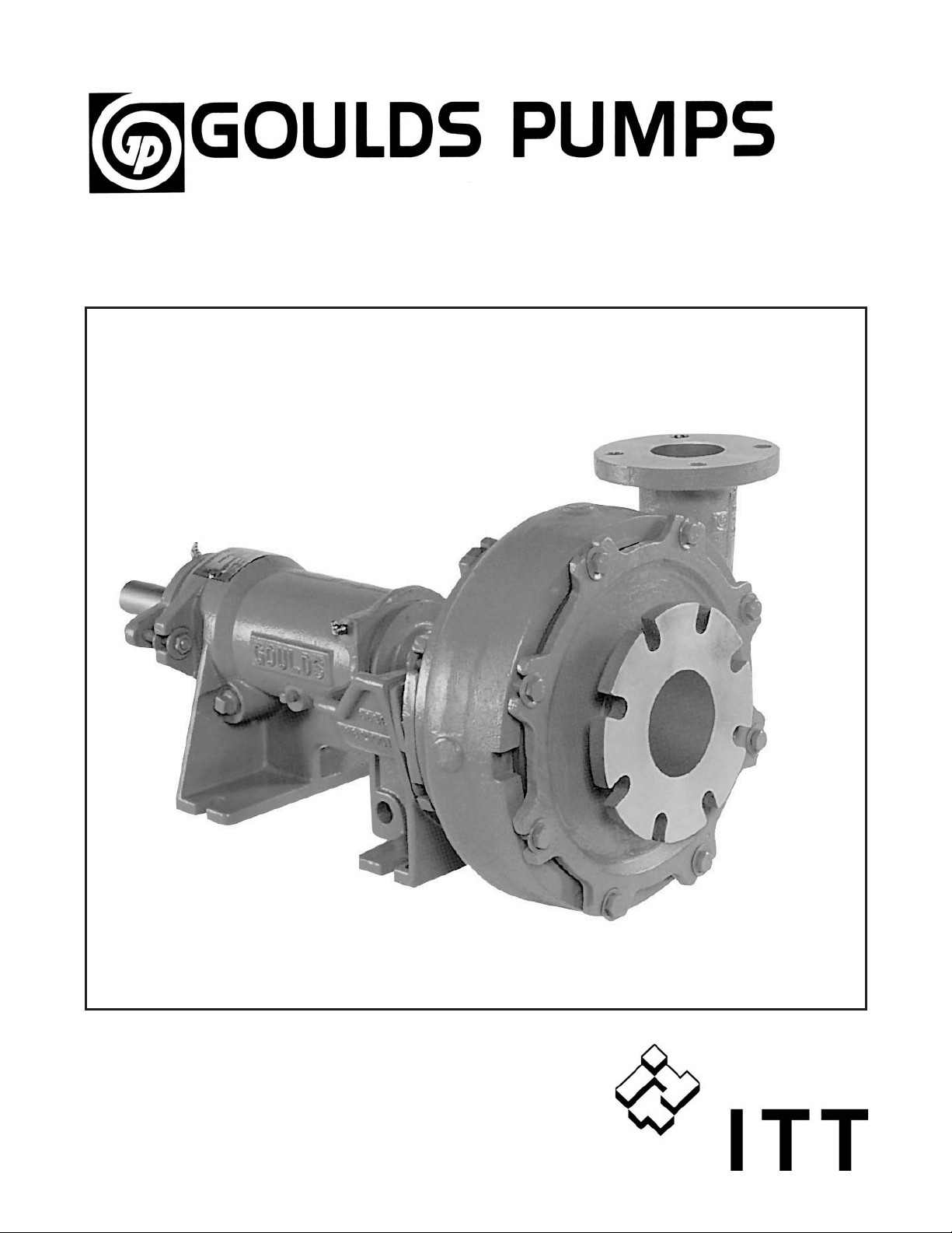
Installation, Operation and Maintenance Instructions
Model JC
Page 2

Pump Safety Tips
Safety Apparel:
Insulated work gloves when handling
•
hot bearings or using bearing heater
Heavy work gloves when handling
•
parts with sharp edges, especially impellers
Safety glasses (with side shields) for
•
eye protection, especially in machine
shop areas
Steel-toed shoes for foot protection when
•
handling parts, heavy tools, etc.
Other personal protective equipment to protect
•
against hazardous/toxic fluids
Coupling Guards:
• Never operate a pump without a coupling guard
properly installed
Flanged Connections:
• Never force piping to make a connection with a
pump
• Use only fasteners of the proper size and material
Operation:
Do not operate below minimum rated flow, or with
suction/discharge valves closed
Do no open vent or drain valves, or remove plugs while
system is pressurized
Maintenance Safety:
Always lockout power
•
Ensure pump is isolated from system and pressure is
•
relieved before disassembling pump, removing plugs,
or disconnecting piping
Use proper lifting and supporting equipment to
•
prevent serious injury
Observe proper decontamination procedures
•
• Know and follow company safety regulations
• Never apply heat to remove impeller
• Observe all cautions and warnings highlighted in
pump instruction manual.
• Ensure there are no missing fasteners
•
Beware of corroded or loose fasteners
2 JC IOM 11/06
Page 3

IMPORTANT SAFETY REMINDER
To: Our Valued Customers
Goulds' pumps will provide safe, trouble-free service when properly installed, maintained, and operated. We have an
extensive network of experienced sales and service professionals to assist in maximizing your satisfaction with our products.
Safe installation, operation, and maintenance of Goulds' equipment are an essential end user responsibility. This Instruction,
Operation, and Maintenance (IOM) manual identifies specific safety risks that must be considered at all times during product
life. Understanding and adhering to these safety warnings is mandatory to ensure person- nel, property, and/or the environment
will not be harmed. Adherence to these warnings alone, however, is not sufficient — it is anticipated that the end user will also
comply with industry and corporate safety standards. Identifying and eliminating unsafe installation, operating and maintenance
practices is the responsibility of all individuals involved in the installation, operation, and maintenance of industrial equipment.
Specific to pumping equipment, two significant risks bear reinforcement above and beyond normal safety precautions.
! WARNING
▲
Operation of any pumping system with a blocked suction and discharge must be avoided in all cases. Operation, even
for a brief period under these conditions, can cause superheating of enclosed pumpage and result in a violent
1
explosion. All necessary measures must be taken by the end user to ensure this condition is avoided.
! WARNING
▲
Pumping equipment Instruction, Operation, and Maintenance manuals clearly identify accepted methods for
disassembling pumping units. These methods must be adhered to. Specifically, applying heat to impellers and/or
2
impeller retaining devices to aid in their removal is strictly forbidden. Trapped liquid can rapidly expand and result
in a violent explosion and injury.
Please take the time to review and understand the safe installation, operation, and maintenance guidelines outlined in this
manual.
JC IOM 11/06
3
Page 4

This page intentionally left blank.
4 JC IOM 11/06
Page 5

TABLE OF CONTENTS
PAGE SECTION
7 SAFETY
11 GENERAL INFORMATION
13 INSTALLATION
17 OPERATION
21 PREVENTIVE MAINTENANCE
27 SPARE PARTS
1
2
3
4
5
6
31 APPENDIX
7
JC IOM 11/06 5
Page 6

This page intentionally left blank.
6 JC IOM 11/06
Page 7

SAFETY
DEFINITIONS......................................7
GENERAL PRECAUTIONS ..............................8
EXPLOSION PREVENTION .............................8
SPECIAL ATEX CONSIDERATIONS ........................8
ATEX IDENTIFICATION ...............................9
INTENDED USE ....................................9
CONDITION MONITORING .............................9
DEFINITIONS
1
These pumps have been designed for safe and reliable
operation when properly used and maintained in
accordance with instructions contained in this manual. A
pump is a pressure containing device with rotating parts
that can be hazardous. Operators and maintenance
personnel must realize this and follow safety measures.
ITT Industries Goulds Pumps is not liable for physical
injury, damage or delays caused by a failure to observe the
instructions in this manual.
Throughout this manual the words WARNING,
CAUTION, ELECTRICAL, ATEX, and NOTE are used
to indicate procedures or situations which require special
operator attention:
! WARNING
s
Operating procedure, practice, etc. which, if not
correctly followed, could result in personal injury or
loss of life.
! CAUTION
$
Operating procedure, practice, etc. which, if not
followed, could result in damage or destruction of
equipment.
EXAMPLES
! WARNING
s
Pump must never be operated without coupling guard
installed correctly.
$
Throttling flow from the suction side may cause
cavitation and pump damage.
Improper impeller adjustment could cause contact
!
between the rotating and stationary parts, resulting
in a spark and heat generation.
Lock out driver power to prevent electric shock,
"
accidental start-up and physical injury.
NOTE: Proper alignment is essential for long pump
life.
CAUTION
If equipment is to be installed in a potentially
!
explosive atmosphere and these procedures are not
followed, personal injury or equipment damage from
an explosion may result.
Particular care must be taken when electrical power
"
source to the equipment is energized.
NOTE: Operating procedure, condition, etc. which is
essential to observe.
JC IOM 11/06
7
Page 8

GENERAL PRECAUTIONS
NEVER apply heat to remove impeller. It may
!
s
explode due to trapped liquid.
NEVER use heat to disassemble pump due to risk
!
s
of explosion from trapped liquid.
NEVER operate pump without coupling guard
!
s
correctly installed.
NEVER operate pump beyond the rated
!
l
conditions to which the pump was sold.
NEVER start pump without proper prime or
!
l
proper liquid level in self-priming pumps.
Cooling systems such as those for bearing
lubrication, mechanical seal systems, et, where
provided, must be operating properly to prevent
excess hear generations, sparks, and premature
failure.
s
NEVER run pump below recommended
!
l
minimum flow or when dry.
ALWAYS lock out power to the driver before
!
performing pump maintenance.
NEVER operate pump without safety devices
!
s
installed.
NEVER operate pump with discharge valve
!
s
closed.
DO NOT change conditions of service without
approval of an authorized Goulds representative.
Rotate shaft by hand to ensure it rotates smoothly
and there is no rubbing which could lead to
excess hear generation and or sparks
Ensure that pump and systems are free of foreign
objects before operating and that objects cannot
enter the pump during operation. Foreign objects
in the pumpage or piping system can cause
blockage of flow which can result in excess heat
generation, sparks and premature failure.
EXPLOSION PREVENTION
In order to reduce the possibility of accidental explosions in atmospheres containing explosive gasses and/or dust, the
!
instructions under the ATEX symbol must be closely followed. ATEX certification is a directive enforced in Europe for
non-electrical and electrical equipment installed in Europe. ATEX requirements are not restricted to Europe, and are
useful guidelines for equipment installed in any potentially explosive environment.
SPECIAL ATEX CONSIDERATIONS
All installation and operation instructions in this manual
must be strictly adhered to. In addition, care must be taken
to ensure that the equipment is properly maintained. This
includes but is not limited to:
1. Monitoring the pump frame and liquid end
temperature.
2. Maintaining proper bearing lubrication.
3. Ensuring that the pump is operated in the intended
hydraulic range.
8 JC IOM 11/06
Page 9

ATEX IDENTIFICATION
For a pumping unit (pump, seal, coupling, motor and pump
accessories) to be certified for use in an ATEX classified
environment, the proper ATEX identification must be
present.
The ATEX tag would be secured to the pump or the
baseplate on which it is mounted. A typical tag would look
like this:
The CE and the Ex designate the ATEX compliance. The
code directly below these symbols reads as follows:
II = Group 2
2 = Category 2
G/D = Gas and Dust present
T4 =
Temperature class, can be T1 to T6
(see Table 1)
Table 1
Maximum Process Temperature
to Achieve Desired T Rating
Maximum
T Rating
per EN
1127-1
T1 450 410
T2 300 260
T3 200 165
T4 135 100
T5 100 65
T6 85 50
The code classification marked on the equipment should be
in accordance with the specified area where the equipment
will be installed. If it is not, please contact your
ITT/Goulds representative before proceeding.
Surface
Temperature
in Celsius
Maximum
Process
Temperature
in Celsius
1
INTENDED USE
The ATEX conformance is only applicable when the pump
unit is operated within its intended use. All instructions
within this manual must be followed at all times.
Operating, installing or maintaining the pump unit in any
way that is not covered in this manual can cause serious
personal injury or damage to the equipment. This
CONDITION MONITORING
For additional safety precautions, and where noted in
this manual, condition monitoring devices should be
used. This includes, but is not limited to:
Pressure gauges
•
Flow meters
•
Level indicators
•
Motor load readings
•
Temperature detectors
•
Bearing monitors
•
Leak detectors
•
PumpSmart
•
®
control system
includes any modification to the equipment or use of parts
not provided by ITT/Goulds. If there is any question
regarding the intended use of the equipment, please contact
an ITT/Goulds representative before proceeding.
For assistance in selecting the proper instrumentation and
its use, please contact your ITT/Goulds representative.
Do not insulate bearing housings as this can result
!
in excess heat generation, sparks and premature
failure.
Check for magnetism on the pump shaft and
!
degauss the shaft if there is any detectable
magnetism. Magnetism will attract ferritic objects to
the impeller, seal and bearings which can result in
excess heat generation, sparks and premature
failure.
JC IOM 11/06
9
Page 10

Leakage of process liquid may result in creating an
!
explosive atmosphere. Ensure the materials of the
pump casing, impeller, shaft, sleeves, gaskets and
seals are compatible with the process liquid.
Leakage of process liquid may result in creating an
!
explosive atmosphere. Follow all pump and seal
assembly procedures.
A build up of gases within the pump, sealing system
!
and or process piping system may result in an
explosive environment within the pump or process
piping system. Ensure process piping system, pump
and sealing system are properly vented prior to
operation.
10 JC IOM 11/06
Page 11
GENERAL INFORMATION
INTRODUCTION ...................................11
IMPORTANCE OF INSTRUCTIONS ........................11
SPECIAL WARNINGS ................................11
RECEIVING INSPECTION - SHORTAGES ....................11
INTRODUCTION
This instruction manual is intended to assist those involved
with the installation, operation and maintenance of Goulds
Ashland Operations slurry pumps. It is recommended that
this manual be thoroughly reviewed prior to installing or
performing any work on the pump or motor.
IMPORTANCE OF INSTRUCTIONS
2
The design, material and workmanship incorporated in the
construction of Goulds Ashland Operations slurry pumps
makes them capable of giving long, trouble-free service.
The life and satisfactory service of any mechanical unit,
however, is enhanced and extended by periodic inspection
SPECIAL WARNINGS
Goulds Ashland Operations will not be liable for any
damages or delay caused by failure to comply with the
provisions of this instruction manual. This pump is not to
be operated at speeds, working pressures, discharge
RECEIVING INSPECTION - SHORTAGES
Care should be taken when unloading pumps. If shipment is
not delivered in good order and in accordance with the bill
of lading, note the damage or shortage on both receipt and
freight bill. Make any claims to the transportation
company promptly.
and careful maintenance. This manual was prepared to
assist operators in understanding the construction and
correct methods of installing, operating, and maintaining
these pumps.
pressures, or temperatures higher than, nor used with
liquids other than, stated in the original order
acknowledgment, without written permission of the
Ashland Operations, Goulds Pumps, Inc.
JC IOM 11/06
11
Page 12

This page intentionally left blank.
12 JC IOM 11/06
Page 13

INSTALLATION
PREPARATION FOR SHIPMENT .........................13
INSTALLATION....................................13
PIPING .........................................13
FOUNDATION .....................................14
PUMP DRIVER ALIGNMENT............................15
This section is a general installation and operating
instruction for most Goulds pumps. Specific text and
illustrations are included in this section. To insure pump
performance and operating life, proper installation and
PREPARATION FOR SHIPMENT
Goulds pumps are prepared at the factory for shipment
under covered conditions. They are protected for transport
and short term covered storage. Unless otherwise specified,
INSTALLATION
Equipment that will operate in a potentially explo-
!
sive environment must be installed in accordance
with the following instructions.
All equipment being installed must be properly
!
grounded to prevent unexpected static electric
discharge. If not, a static electric discharge may
occur when the pump is drained and disassembled
for maintenance purposes.
reasonable maintenance are required. The following
instructions are a guide for installation and maintenance
personnel and the pump operator.
3
it is assumed the pump will be installed upon delivery.
Additional protection can be provided by request.
LOCATION OF UNIT
The pump should be located in a clean, dry area free from
flooding. The area should provide adequate space for
maintenance and repair, considering complete disassembly
and handling of equipment. The unit should be positioned
to provide the most efficient pipeline system.
! WARNING
s
A
Never draw piping into place by forcing at the flanged
connections of the pump. This may impose dangerous
strains on the unit and cause misalignment between
pump and driver. Pipe strain will adversely effect the
operation of the pump resulting in physical injury and
damage to the equipment
$
A
Pump must never be throttled on suction side.
JC IOM 11/06
CAUTION
PIPING
A
NPSHa must always exceed NPSHr as shown on
Goulds performance curves received with order.
Reference Hydraulic Institute for NPSH and pipe
friction values needed to evaluate suction piping
Short, direct suction and discharge pipelines and a
minimum of elbows and fittings result in the least amount
of pipe friction.
! WARNING
s
13
Page 14

SUCTION PIPING
1. Excessive friction losses will cause cavitation.
2. Must be kept free of air leaks, particularly in long lines
or conditions of high suction lift.
3. Flow regulating valves must not be located on suction
side of the pump.
DISCHARGE PIPING
1. Excessive friction losses result in insufficient head.
2. A check valve should be located in the discharge line
to protect the pump from reverse flow and excessive
pressure.
FOUNDATION
The foundation must be a permanent, rigid support for the
subbase or floorplate. It should be an industrially accepted
design capable of absorbing excessive vibration.
Foundations are typically concrete with anchor bolts cast in
to secure the pump.
PIPING SUPPORT
The pumps are not designed to carry loads imposed by the
weight of the pipeline. Suction and discharge piping must
be supported near the pump, unless otherwise specified.
Pumps and subbases can be designed to carry loads due to
thermal expansion.
An anchor bolt assembly consists of a bolt and washer with
a sleeve 2-½ times the diameter of the bolt. When the
assembly is cast in concrete, the washer prevents the sleeve
and bolt from being pulled. The sleeve I.D. provides an
adjustment allowance around the bolt. A lug is generally
welded on the bolt to prevent rotation when tightening.
Anchor bolts should be located in the concrete by a
template dimensioned from the pump installation drawing.
The top of the sleeve should be temporarily sealed with
waste material to prevent concrete from entering during the
concrete pouring operation. A typical anchor bolt
arrangement is shown in Figure W1.
INSTALLING PUMPON
FOUNDATION
If subbases or floorplates were directly anchored to poured
concrete foundations, surface irregularities would cause
distortion. Rectangular metal blocks and shims, or metal
wedges having a small taper, are placed beside each anchor
bolt to level the subbase or floorplate (see Fig. W2 and Fig.
W3 on the following page). The anchor bolts are then
drawn tight enough to maintain position and level.
To secure the shims in place and provide a level surface for
the base or plate, grout is poured over the concrete
foundation. A ¾" to 1-½" grout allowance is recommended.
When subbases have cavities, grout holes are provided to
fill all spaces. After the grout has hardened, permanently
tighten the anchor bolts.
14 JC IOM 11/06
Page 15

When the grout has hardened and the anchor bolts are
permanently secured, recheck level.
NOTE: On large subbases/floorplates, shimming is
recommended to be at 24" spacing.
PUMP-DRIVER ALIGNMENT
Alignment procedures must be followed to prevent
!
unintended contact of rotating parts. Follow
coupling manufacturer’s installation and operation
procedures.
3
spaced around the coupling. The unit will be in angular
alignment when the measurements show that the coupling
faces are the same distance apart at all points (Fig. W7).
SHAFT ALIGNMENT OF
HORIZONTALPUMP AND DRIVER
Pumps and drivers that are received from the factory with
both machines mounted on a common subbase were
accurately aligned before shipment. Because all subbases
are, to some extent, flexible, factory alignment may be
altered during shipment and handling. After the subbase
has been leveled, grouted, and secured, check the
alignment. Alignment should be rechecked after the pump
is fully installed and before startup. Refer to the Alignment
Procedure.
Disconnect coupling halves before proceeding with
alignment. Check for angular and parallel alignment in the
Alignment Procedure. The faces and outside diameters of
the coupling halves must be square and concentric with the
bores. If this condition does not exist, the Alternate Method
of Alignment is recommended.
Subbase mounted horizontal pumps may be shipped with or
without drivers and gears. Be sure pump and drivers are
uncoupled before installation. Level by shimming beside
each anchor bolt and grout as described in Installing Pump
on Foundation.
ALIGNMENT PROCEDURE
A check for angular alignment is made by inserting the taper
gauge or feelers at four points between the coupling faces
and comparing the distance between the faces at four points
A check for parallel alignment is made by placing a straight
edge across both coupling rims at the top, bottom, and at
both sides. The unit will be in parallel alignment when the
straight edge rests evenly on the coupling rim at all
positions. Allowance may be necessary for temperature
changes and for coupling halves that are not of the same
outside diameter.
NOTE: Care must be taken to have the straight edge
parallel to the axis of the shafts (Fig. W8).
JC IOM 11/06
15
Page 16

Angular and parallel misalignment are corrected by means
of shims under the motor mounting feet. After each change,
it is necessary to recheck the alignment of the coupling
halves. Adjustment in one direction may disturb
adjustments already made in another direction. It should not
be necessary to adjust the shims under the pump.
The permissible amount of misalignment will vary with the
type of pump and driver. The manufacturer’s recommendations should be obtained and followed.
With this method, accurate alignment of shaft centers can
be obtained even where faces or outside diameters of the
coupling halves are not square or concentric with the bores,
provided all measurements for angular alignment are made
between the same two points on the faces, and all
measurements for parallel alignment are made between the
same two points on the outside diameters. Gross deviations
in squareness or concentricity, however, may cause
problems due to coupling unbalance or abnormal coupling
wear and may need to be corrected for reasons other than
accomplishment of shaft alignment.
ALIGNMENT OF GEAR TYPE
COUPLINGS
Gear type couplings are aligned in the same manner as
outlined above. However, the coupling covers must be
moved back out of the way and measurements made on the
coupling hubs as shown on Fig. W9.
When the driver is to be mounted on the subbase in the
field, it is necessary to place the subbase with pump on the
foundation to level the pump shaft, to check the coupling
faces, the suction and discharge flanges for horizontal or
vertical position, and to make any necessary corrective
adjustments.
When the units are lined up cold, it may be necessary to
make an allowance for the vertical rise of the driver and/or
pump caused by heating. Goulds Pumps recommendations
should be obtained and followed.
ALTERNATE METHOD OF
ALIGNMENT
An approved method for putting the coupling halves in final
accurate alignment is by the use of a dial indicator. Check
alignment by straight edge, taper gauge or feelers as
accurately as possible by the procedure indicated above.
Bolt the indicator to the pump half of the coupling, with the
indicator button resting on the other half coupling periphery, set the dial to zero, and chalk mark the coupling half
at the point where the button rests. For any check, top,
bottom, or sides, rotate both shafts by the same amount;
i.e., all readings on the dial must be made with button on
the chalk mark.
FACTORS THAT MAY DISTURB
ALIGNMENT
The unit should be checked periodically for alignment. If
the unit does not stay in line after being properly installed,
the following are possible causes:
l
Settling, seasoning or spring of the foundation.
l
Wear of the bearings.
l
Pipe strains distorting or shifting the machine.
l
Springing of the baseplate by heat from an adjacent
steam pipe or from a steam turbine.
l
Shifting of the building structure due to variable loading
or other causes.
l
The readings will indicate whether the driver has to be
Loose nuts or bolts on the pump or driver assembly.
raised or lowered or moved to either side. After each
movement, check to see that coupling faces remain parallel
to one another.
16 JC IOM 11/06
Page 17

OPERATION
PREPARATION FOR START-UP ..........................17
PUMP START-UP ...................................18
LOCATING PROBLEMS ...............................20
PREPARATION FOR START-UP
STUFFING BOXES
In the conventional stuffing box, mechanical seals and
packing seal between the stationary and rotating
components of the pump. Generally, a clear liquid such as
water is forced through the stuffing box to lubricate the
sealing elements. The lubricating liquid pressure must
exceed the pressure of the pumpage at the stuffing box. For
end suction pumps, lubricating liquid pressure should be
10-15 PSIG higher than the discharge pressure. For side
and double suction pumps, lubricating liquid pressure
should be 10-15 PSIG higher than the suction pressure.
NOTE: To determine suction or discharge pressure,
use gauge pressure only.
4
The piping supplying the lubrication liquid should be fitted
tightly to prevent air from entering. On suction lifts, a small
quantity of air entering the pump at this point may result in
loss of suction.
Lubrication liquid pressure is controlled by a valve on the
outlet piping. Since the liquid leaking from the stuffing box
should be clear, control of the packing lubricant will vary
with the condition of the packing. Increase pressure within
the stuffing box by closing outlet valve. Adjustments
should be slow and consistent with the run-in procedure for
new packing.
The lubricating liquid must be clean, free of grit and acid.
Shaft sleeve scoring, packing destruction, and mechanical
seal face damage will result from contaminated lubricant.
PACKING
Packed stuffing boxes are not allowed in an ATEX
!
classified environment.
Original equipment packing is a suitable grade for the
service intended. To replace original packing, contact your
local Goulds representative.
Refer to Bill of Material and Assembly Drawing for
specific packing size and configuration.
PACKING PROCEDURE
1. Stuffing box and shaft sleeve must be clean and free of
grit.
2. Form packing over shaft or mandrel of same diameter.
Carefully cut to packing length. Discard rings cut too
short.
3. Pre-form each ring by coiling 1-½ turns.
4. To install packing rings, do not pull straight. Expand
the coil as a coil spring. (See Fig. W13.)
JC IOM 11/06
17
Page 18

5. Expand first coil as shown and insert into stuffing box.
Tamp packing to stuffing box shoulder firmly with the
gland. Note where the cut is positioned.
6. Install second and third coils as required by assembly
drawing, staggering the cut 90º-120º.
7. Insert seal cage (lantern ring) into stuffing box,
carefully noting its proper position on assembly
drawing. Failure to properly locate seal cage will result
in insufficient packing lubrication. Packing and shaft
sleeve damage will occur.
8. After packing and seal cage are properly installed,
insert gland into stuffing box. Tighten gland nuts
finger-tight only. Shaft should turn freely.
NOTE: Do not over tighten gland nuts. Packing may
set permanently and require removal. Over tightened
packing causes excessive friction between packing and
sleeve, and will result in damaged components. A
noticeable temperature increase in stuffing box would
indicate insufficient lubrication.
9. Follow pump start-up procedure. Turn on stuffing box
lubricating liquid and start pump.
10. A significant amount of lubricating liquid should leak
from gland side of stuffing box. Operate pump for at
least 15 minutes before tightening gland nuts. Make
small, even gland nut adjustments to reduce leakage.
Allow adequate run-in time between adjustments.
Acceptable leakage is 30-50 drops per minute.
11. Periodic maintenance is absolutely required for all
packed pumps.
Normal shaft run-out should be under .005" to avoid
pounding of stuffing box packing. With excessive shaft
run-out, shaft straightening or replacement is necessary.
MECHANICAL SEALS
The mechanical seal used in an ATEX classified
!
environment must be properly certified.
The mechanical seal must have an appropriate seal
!
flush system. Failure to do so will result in excess
heat generation and seal failure.
Most mechanical seals are installed and adjusted at the
factory. Due to size and design, some installed mechanical
seals are supplied with shipping retainers. Shipping
retainers hold the sealing faces apart to avoid damage
during transport. Shipping retainers must be removed
before shaft is to be rotated. Pumps with retained seal faces
will be specially marked and instructions from the seal
manufacturer for retainer removal will be provided.
Mechanical seals have a stationary and a rotating sealing
face. Commonly, these sealing rings are of carbon and
ceramic material, brittle in nature, and easily damaged. As
the sealing rings seat with the operation of the pump, a
compatible wear pattern develops between the mating
surfaces. To disassemble the mechanical seal after the wear
pattern is established would necessitate the replacement of
the rotating and stationary sealing elements. Do not replace
only one component.
To insure the life and sealing characteristics of the
mechanical seal, lubricating liquid must be circulated
through the stuffing box. Clear, grit free liquid is
necessary.
Special seal information and replacement seal elements
should be provided by the seal manufacturer. Goulds
strongly recommends the stocking of replacement sealing
elements.
$
Do not make shaft adjustments on mechanical seal
installations without consulting seal instructions and
pump assembly drawing.
CAUTION
PUMP START-UP
Service temperature in an ATEX classified
!
environment is limited to the area classification
specified on the ATEX tag affixed to the pump
(reference Table 1 in the ATEX identification
section).
The coupling used in an ATEX classified
!
environment must be properly certified.
18 JC IOM 11/06
The coupling guard used in an ATEX classified
!
environment must be constructed from a nonsparking material.
START-UP PRECAUTIONS
1. All equipment and personal safety related devices and
controls must be installed and operating properly.
2. To prevent premature pump failure at initial start up
due to dirt or debris in the pipe system, ensure the
system has been adequately cleaned and flushed.
Page 19

3. Variable speed drivers should be brought to rated
speed as quickly as possible
4. Variable speed drivers should not be adjusted or
checked for speed governor or over speed trip settings
while coupled to the pump at initial start up. If settings
have not been verified, uncouple the unit and refer to
driver manufacturer's instructions for assistance.
Pumpage temperatures in excess of 200°F will require
warmup of pump prior to operation. Circulate a small
amount of pumpage through the pump until the casing
temperature is within 100°F of the pumpage temperature
and evenly heated.
LUBRICATING LINES TO STUFFING
BOX
Lubricating liquid must be flowing to the stuffing box
before the pump is started. Both mechanical seals and
packing require lubrication for continuous service.
PRIMING
The pump must be completely primed before operation.
Pumps must be fully primed at all times during
!
operation.
$
When starting the pump, immediately observe pressure
gauges. If discharge pressure is not quickly attained,
stop driver, reprime and attempt to restart.
CAUTION
BEARING LUBRICATION
Bearings must have adequate lubrication. Engage external
lubrication system. Consult “BEARING SECTION” of
these instructions for specific information.
SHAFT ROTATION
The pump shaft must turn without any binding or rubbing.
By manually turning the rotating element, only the uniform
frictional drag of the bearings and the stuffing box should
be sensed.
$
Serious damage may result if the pump is run in the
wrong direction
CAUTION
CORRECT ROTATION OF THE
DRIVER
The direction of rotation of the driver must be checked
before it can be coupled with the pump. The direction of
rotation of the pump is indicated in a prominent location.
For pumps with impellers threaded on the shaft, reverse
rotation would back the shaft from the impeller thread.
Considerable damage may occur.
WATER HAMMER
Water hammer is a high pressure surge within a closed pipe
system, created by rapid change in the flow rate. Changes
in the flow rate occur when there are sudden changes in
pump speed. The most common cause is the sudden
opening or closing of a valve or flow control device.
Extensive damage to the pump and pipeline is a result of
water hammer.
FREEZING
If the pump is exposed to below freezing temperatures, the
liquid should be drained during idle periods.
Lock out driver power to prevent electric shock,
"
accidental start-up and physical injury.
When installing in a potentially explosive
!
environment, ensure that the motor is properly
certified.
JC IOM 11/06
19
Page 20

LOCATING PROBLEMS
CONDITIONS LEADING TO
INSUFFICIENT OR NO DISCHARGE
Insufficient speed.
l
Excessive discharge head
l
Insufficient NPSH.
l
Worn pump components
l
Incorrect direction of rotation
l
Incomplete pump priming
l
Impeller or discharge pipe clogged
l
Pumpage viscosity too high
l
CONDITIONS LEADING TO
EXCESSIVE POWER
CONSUMPTION
Excessive speed.
l
Pump operating at high horsepower area of the pump
l
curve (off design point)
Mechanical binding or rubbing of rotating element.
l
l
Pumpage specific gravity and/or viscosity too high
$
Damage occurs from:
Increased vibration levels – affects bearings, stuffing
•
box or seal chamber and mechanical seal
Increased radial loads – Stresses on shaft and bearings
•
Heat build up–Vaporization causing rotating parts to
•
score or seize
Cavitation–Damage to internal surfaces of pump
•
$
Observe pump for vibration levels, bearing temperature
and excessive noise. If normal levels are exceeded, shut
down and resolve.
! WARNING!
s
This unit must never be used without prior installation
of the safety guards for rotating parts as prescribed by
O.S.H.A.
Operation of this pump with both suction and
discharge valves closed for even brief periods of time is
an unacceptable and dangerous practice. it can rapidly
lead to a violent pump failure.
CAUTION
CAUTION
$
Always vary capacity with regulating valve in the
discharge line. NEVER throttle flow from the suction
side
$
Driver may overload if the pumpage specific gravity
(density) is greater than originally assumed, or the
rated flow rate is exceeded
$
Always operate the pump at or near the rated
conditions to prevent damage resulting form cavitation
or recirculation
! WARNING
s
Do not operate pump below minimum rated flows or
with suction and/or discharge valve closed. These
conditions may create an explosive hazard due to
vaporization of pumpage and can quickly lead to pump
failure and physical injury.
CAUTION
CAUTION
CAUTION
! WARNING!
s
Inspection intervals should be shortened appropriately
if the pumpage is abrasive and/or corrosive, or if the
environment is classified as potentially explosive.
! WARNING!
s
DO NOT apply heat to hub or nose of threaded
impeller. There is a danger of explosion.
20 JC IOM 11/06
Page 21

PREVENTIVE MAINTENANCE
GENERAL COMMENTS ...............................21
MAINTENANCE SCHEDULE ............................21
LIQUID END ......................................22
POWER END......................................23
IMPELLER CLEARANCES .............................23
MAINTENANCE OF BEARINGS ..........................24
GENERAL COMMENTS
A routine maintenance program can extend the life of your pump. Well maintenanced equipment will last longer and
require fewer repairs. It is recommended maintenance records be kept – this will help pinpoint potential causes of
problems.
The Preventive Maintenance section must be adhered to in order to keep the applicable ATEX classification of the
equipment. Failure to follow these procedures will void the ATEX classification for the equipment.
MAINTENANCE SCHEDULE
5
Routine Maintenance
Bearing lubrication
•
Seal Monitoring
•
Vibration analysis
•
Discharge pressure
•
Temperature monitoring
•
Routine Inspections
Check level and condition of oil through sight glass
•
on bearing housing.
Check for unusual noise, vibration and bearing
•
temperatures.
Inspect pump and piping for leaks.
•
Check stuffing box leakage.
•
Packing: Excessive leakage requires adjustment or
•
possible packing replacement.
Mechanical Seal: Should be no leakage.
•
Quarterly Inspections
Check foundation and hold-down bolts for tightness.
•
If pump has been left idle, check packing. Replace if
•
required.
Oil should be changed at least every 3 months or
•
more often if there are any adverse atmospheric
conditions or other conditions which might
contaminate or break down the oil.
JC IOM 11/06
21
Page 22

LIQUID END
TO DISASSEMBLE THE LIQUID
END
1. Drain pumpage from pump and pipe line. Disconnect
auxiliary lubrication lines, suction and discharge pipe
line connections. Uncouple pump from driver.
! WARNING
s
When handling hazardous and/or toxic fluids, proper
personal protective equipment should be worn. If pump
is being drained, precautions must be taken to prevent
physical injury. Pumpage must be handled and
disposed of in conformance with applicable
environment regulations.
2. Remove cap screws or bolts which fasten suction disc
(182)to casing (100).
3. Remove suction disc (182) and suction disc liner
(100B) from casing fit.
4. Impeller (101) is threaded onto shaft (122). Remove
impeller by restraining coupling end of shaft and
turning impeller in the operating direction of rotation.
Do not apply heat.
NOTE: If impeller is frozen on shaft, restrain the impeller,
attach a spanner wrench to coupling end of shaft, and give
the wrench a sharp blow.
! WARNING!
s
DO NOT apply heat to hub or nose of threaded
impeller. There is a danger of explosion.
5. Remove cap screws or bolts which fasten casing (100)
to hub disc (184). Slide casing from hub disc fit.
3. Position casing (100) with gasket into hub disc (184)
fit. Be sure discharge is in proper orientation. Fasten
casing to hub disc with cap screws (370J).
4. Install impeller (101) with gasket onto shaft (100)
Drawing impeller tight on shaft threads firmly secures
shaft sleeve. Seal sleeve to impeller with RTV silicone.
5. Place suction disc liner (100B) into casing fit. With
O-ring (412F) in position on liner O.D., install suction
disc (182). Fasten suction disc to casing with cap
screws (370E).
6. Set impeller clearance according to section Impeller
Clearance in the bearing section of this manual.
Improper impeller adjustment could cause contact
!
between the rotating and stationary parts, resulting
in a spark and heat generation.
The impeller clearance setting procedure must be
!
followed. Improperly setting the clearance or not
following any of the proper procedures can result in
sparks, unexpected heat generation and equipment
damage.
7. Install packing (106), seal cage (105) and gland (107).
Refer to assembly drawing for proper packing
sequence and to section Stuffing Boxes in the General
Instructions.
8. Install pump half of coupling or sheave. Realign pump
and driver. Connect pump section and discharge to
pipe line. Connect auxiliary lubrication lines.
9. Start-up instructions.....Refer to General Instructions
6. Disassemble gland (107) from stuffing box.
7. Remove bolts which fasten hub disc (184) and bearing
frame (228). Carefully pull hub disc from shaft sleeve
(126). Packing (106) and seal cage (105) may be left in
stuffing box during disassembly of hub disc and
removed hub disc is separated from bearing assembly.
8. Pull or drive shaft sleeve (126) from shaft (100) if
replacement is necessary.
TO ASSEMBLE THE LIQUID END
1. Shaft (122) and shaft sleeve (126) must be clean and
free of burrs. Install sleeve (126) on shaft.
2. Carefully guide hub disc (184) stuffing box over
impeller end of shaft. Secure hub disc (184) to bearing
frame (228) with bolts (370C).
22 JC IOM 11/06
Page 23

POWER END
“J ” TYPE BEARING
The “J” type bearing assembly uses medium-heavy ball
bearings. On the small size “J” bearings, double row ball
bearings are used for combined loading. The larger sizes
utilize separate radial and thrust ball bearings. Adjustment
of nose clearance can be easily accomplished without
bearing disassembly.
IMPELLER CLEARANCES
Improper impeller adjustment could cause contact
!
between the rotating and stationary parts, resulting
in a spark and heat generation.
The impeller clearance setting procedure must be
!
followed. Improperly setting the clearance or not
following any of the proper procedures can result in
sparks, unexpected heat generation and equipment
damage.
To maintain maximum operating efficiency, a uniform
1/64" - 1/32" clearance between the parallel surfaces of
suction disc liner (100B) and the nose of the impeller (101)
is necessary. The clearance is adjusted by moving shaft
(122) toward or away from suction disc liner (100B). There
are adjusting lugs cast on bearing frame (228) and thrust
bearing housing (134A). Studs (356A) threaded into thrust
bearing housing lugs fit through the slots of bearing frame
lugs. Jam nuts on studs, located on both sides of the frame
lugs, are used to adjust and fasten the thrust bearing
housing relative to the bearing frame.
METHODS TO DETERMINE
IMPELLER NOSE CLEARANCE
During Installation Or Repair
With a feeler gauge, measure the gap between the nose of
the impeller and the casing liner on the suction side.
During Normal Service
Move impeller toward suction side of casing liner until
parallel surfaces slightly rub. Measure “X” dimension and
add the recommended impeller nose clearance. Adjust
dimension “X” per “Impeller Clearance Adjustment
Procedure.”
Impeller Clearance Adjustment Procedure
1. Turn stud jam nuts at the bearing frame lugs to drive
the shaft assembly in the desired direction. Moving
shaft (122) toward suction side casing liner will
decrease the clearance
JC IOM 11/06
2. To decrease impeller clearance, loosen outboard jam
nut and drive the shaft assembly by turning the inboard
jam nut.
3. When desired clearance is reached, tighten outboard
jam nut securely. Check clearance after tightening.
4. To increase impeller clearance, loosen inboard jam nut
and drive the shaft assembly by turning the outboard
jam nut.
$
Jam nuts on both sides of bearing frame lugs must be
secure. Normal impeller thrust will tend to decrease the
impeller clearance. Impeller rubbing will result from
insufficient jam nut tightening.
CAUTION
23
Page 24

Conditions Requiring Adjustments
1. Overheated thrust bearings may develop from uneven
adjustment of jam nuts. Check lubrication.
2. Noise, vibration and wear may result from the impeller
rubbing on the suction or hub side casing liners. Adjust
impeller clearance.
MAINTENANCE OF BEARINGS
3. Poor performance and wear may result from excessive
impeller clearance at the suction side casing liner.
NOTE: Lubricate adjusting studs (356A) for easy
maintenance.
BEARING LUBRICATION AND
CARE
Bearings must be lubricated properly in order to
!
prevent excess heat generation, sparks, and
premature failure.
The Preventive Maintenance section must be
!
adhered to in order to keep the applicable ATEX
classification of the equipment. Failure to follow
these procedures will void the ATEX classification
for the equipment.
Throughout this section on bearing lubrication,
!
different pumpage temperatures are listed. If the
equipment is ATEX certified and the listed
temperature exceeds the applicable value shown in
Table 1 under ATEX identification, then that
temperature is not valid. Should this situation occur,
please consult with your ITT/Goulds representative.
$
Operation of the unit without proper lubrication will
!
cause bearing failure, and pump seizure.
CAUTION
OIL LUBRICATION
When the pump is furnished with oil lubrication, a good
grade of oil should be used to insure long bearing life.
NOTE: Pumps furnished for oil lubrication are
shipped without oil. Add oil until the level is up to the
oil level line before the unit is started.
If too much oil is added, there will be excessive heat
generated in the bearings and there may be leakage from
the shaft seals. We recommend a commercial oil such as
Mobil D.T.E. oil, B.B., Tellus 41 or equal. However, a
good grade of #30 or #40 weight is satisfactory for normal
temperatures.
To 150ºF – SAE 20
To 160ºF – SAE 30
To 175ºF – SAE 40
To 200ºF – SAE 50
GREASE LUBRICATION
When the pump is furnished for grease lubrication, the
pump will be shipped with the bearings hand-packed with
Mobilux #2 grease, unless otherwise specified by the
customer. Other suitable greases are Humble Lidok #2,
Texaco Regal Starfak #2, and Shell Alvania #2. If another
brand is desired, it should be checked with the supplier to
determine if it is equivalent to the above.
Installing A Bearing
The bearings have sufficient grease for at least 24 hours of
operation after start-up. The bearings will run hotter than
normal for the first few hours until the grease is worked out
of the ball path and the bearings have “run in”. Adding
more grease during this period may increase the bearing
temperature.
After the first regreasing, a small amount of grease should
be added at each fitting every 500 hours of operation.
Normal Bearing Temperature
Long bearing life is quite dependent on careful handling of
a bearing when it is out of the housing and during the
installation procedure. Dirt and rough handling are prime
enemies of precision bearings. Bearings should be pressed,
not “hammered” into place. If heat is used to facilitate the
installation, a hot oil bath is the best method. Bearings for
grease lubrication should be hand-packed with grease to
insure adequate lubrication at start-up.
NOTE: The shaft seals above each bearing should be
oiled with a few drops of #30 oil before the pump is
started to insure lubrication of the seal lip.
For best results, the weight of the oil lubricant should be
adjusted for the normal operating temperature as follows:
24 JC IOM 11/06
Page 25

The running temperature for a bearing assembly depends
on many factors such as speed, bearing loads, ambient air
temperature, and condition of bearings. Temperatures
higher than the human hand can tolerate are very
satisfactory for good bearing operation and should not
cause alarm.
For a given speed and loading, the bearing housing
temperature will stabilize at some temperature, usually
below 200º F, which will be the normal temperature for that
installation. Higher temperatures than this normal
temperature, without any change in speed or loading, can
mean a lubrication difficulty or the approach of a bearing
failure.
1. Pull pump coupling half or sheave from drive end of
shaft.
2. Remove radial bearing slinger (123C) from shaft.
3. Remove jam nuts from adjusting studs (356A) which
fasten bearing frame (228) and thrust bearing housing
(134A). Carefully pull the shaft (122), bearings, and
thrust bearing housing (134A) from the drive end of
bearing frame (228). Support both ends of the shaft
assembly to prevent seal and bearing damage.
4. Detach thrust bearing snap ring (361) from thrust
bearing housing (134A). Slide housing over thrust
bearing.
TO DISASSEMBLE THE “J”
BEARING
For the purpose of these instructions, assume the JC liquid
end has been disassembled, including suction disc (182),
suction disc liner (100B), impeller (101), casing (100), hub
disc (184), stuffing box components, and shaft sleeve
(126).
JC IOM 11/06
NOTE: See illustrations for specific thrust bearing
configuration.
5. Remove thrust bearing locknut (136) and lockwasher
(382).
6. Press or pull radial bearing (168C) from shaft (122).
Apply pulling force to inside bearing race only.
25
Page 26

7. Press or pull thrust bearing arrangement from shaft
(122). For double row ball thrust bearing (112C), apply
pulling force to inside race only. For two-bearing
thrust arrangement, apply pulling force to inside race
of thrust bearing (112D). The thrust bearing (112D),
thrust bearing collar (237), and radial bearing (112C)
will be removed.
8. Do not remove radial bearing retainer (119B) from
bearing frame (228). A factory press fit insures a
permanent installation.
TO ASSEMBLE THE “J” BEARING
1. The shaft (122), thrust bearing housing (134A) and
bearings must be clean and free of burrs.
2. To assemble thrust bearing arrangement:
a. Double row ball thrust bearing: (1J-4J)
1) Heat thrust bearing (112C) in 180º F oil
bath.
2) Slide thrust bearing (112C) onto shaft (122)
firmly against shaft shoulder.
3) Install lockwasher (382) and locknut (136)
before bearing cools. When bearing cools to
room temperature, retighten locknut and
secure lockwasher tang.
b. Separate thrust (112C) and radial (112D) bearings
on thrust end (5J):
1) Heat thrust bearing (112D) in 180º F oil
bath and install on shaft (122) firmly
against shaft shoulder.
2) Heat thrust bearing collar (237) in oil bath
and install shaft against inner thrust bearing
inner race.
3 Heat radial bearing (112C) in oil bath and
install on shaft with inner race against
thrust collar (237).
4) Install lockwasher (382) and locknut (136)
before bearings cool. When bearings cool to
room temperature, retighten locknut and
secure with lockwasher tang.
3. To install thrust bearing housing (134A):
a. Double row ball thrust bearing:
1) Lubricate seal (332) and O-ring (496) on
thrust bearing housing (134A).
2) Carefully slide housing (134A) onto shaft
(122) over thrust bearing.
3 Secure housing (134A) with thrust bearing
snap ring (361).
b. Separate thrust (112D) and radial (112C) bearings
on thrust end:
1) Lubricate seal (332) and O-ring (496) on
thrust bearing housing.
2) Carefully slide housing (134A) onto shaft
and bearings until housing shoulder
bottoms on outer race of radial bearing
(112C).
3) Install thrust bearing snap ring (361) into
ring groove of housing.
4) With feeler gauge, measure clearance
between snap ring (361) and outer race of
thrust bearing (112D). The clearance
should be .004 - .010 at “G” gap.
5) From the feeler gauge measurement,
subtract .007”. The resulting dimension is
the thickness of shims (331) at “S” gap.
6) Remove snap ring. Pull housing (134A)
and install calculated shim pack (331)
against housing shoulder. Reinstall housing
and snap ring.
4. Heat radial bearing (168C) in 180º F oil bath. Slide
radial bearing onto shaft (122) firmly against shaft
shoulder. Allow bearing to cool to room temperature
before further assembly.
NOTE: Radial retainer permanently pressed into
bearing frame (228) at factory.
5. Lubricate seal 332 in radial bearing retainer (119B).
Carefully insert the shaft/bearing assembly into the
bearing frame (228) from the drive end. Guide the
threaded end of the shaft through seal (332) in retainer
(119B). As the thrust bearing housing (134A) enters
the bearing frame bore, align adjusting lugs on the
frame and housing.
6. Loosely install adjusting studs (356A) in adjusting
lugs. Do not tighten.
7. Install radial bearing slinger (123C).
26 JC IOM 11/06
Page 27

SPARE PARTS
ORDERING SPARE PARTS .............................27
PARTS LIST ......................................28
JC SECTIONAL VIEW ................................29
ORDERING SPARE PARTS
To insure against possible long and costly downtime
periods, especially on critical services, it is advisable to
have spare parts on hand.
Parts Kit Chart
Parts orders will be handled most promptly if the following
directions are followed.
1. Include pump model and size and its serial number as
shown on the nameplate.
2. For each part required, include the name and part
number.
3. State the quantity required for each part.
4. Provide complete shipping instructions.
RECOMMENDED SPARES
The following are recommended spare parts.
l
1 Suction Liner (100B)
l
1 Impeller (101)
l
1 Lantern Ring (105)
l
5 Packing Rings (106)
l
1 Thrust Bearing (112C)
l
1 Shaft Sleeve (126)
l
1 Radial Bearing (168C)
Pump Size Kit Number
1×1.5-8, 1.5×2-8, 2×3-8 520101
1×1.5-11, 1.5×2-11, 2×3-11 520102
1.5×2-14, 2×3-14 520103
3×4-11 520104
3×4-14, 4×6-14 520105
6×6-14 HS 520106
6×6-14 LS 520107
8×10-18 520108
10×12-22 520109
Parts Kits include thrust bearing locknut, lockwasher and
snap ring, grease seals, and required gaskets and/or
O-rings.
6
l
1 Parts Kit, see chart
JC IOM 11/06
27
Page 28

PARTS LIST
TYPICAL
Item QTY/Pump Part Name Alternate Part Name
100 1
100B
101 1(2)
105
106 5
107 1
112C 1
119B 1
122 1
123C
126 1(2)
134A 1
136 1
168C 1
182 1
184 1
193B 2
222 1
228 1
332 3
351 1(1)
353 2
355 2
356A 2
361 1
370C 4
370E 8
370J 8
382 1
400 1
408 1
412F 1
415 4
496 1
528J 2
528K 8
528L 8
528P 4
1
1 Lantern Ring Seal Cage
Casing
Suction Liner Suction Disc Liner
Impeller
Packing Ring
Gland
Thrust Bearing
End Cover Bearing Retainer
Shaft
Deflector Slinger
Shaft Sleeve
Bearing Housing
Locknut
Radial Bearing
Suction Cover Suction Disc
Stuffing Box Cover Hub Disc
Grease Fitting
Set Screw
Bearing Frame
Grease Seal
Gasket
Stud, Gland
Hex Nut
Stud
Snap Ring
H Cap Screw
H Cap Screw
H Cap Screw
Lockwasher
Key
Pipe Plug
O-Ring
Hex Jam Nut
O-Ring
Washer, 353
Washer, 370E
Washer, 370j
Washer, 356A
®
NOTES:
(1) Buna-N O-Ring 496A replaces gasket 351 on sizes 6x6-14 and 8x10-18.
(2) Sleeve 126 is sealed to impeller 101 with RTV silicone.
All Sizes Except 10x12-22 Grease Lube Bearings.
28 JC IOM 11/06
Page 29

JC SECTIONAL VIEW
JC IOM 11/06 29
Page 30

This page intentionally left blank.
30 JC IOM 11/06
Page 31

APPENDIX
SPECIAL INSTRUCTIONS
A) KAOLIN SERVICE -KJC PUMPS
OPTIMUM IMPELLER RUNNING
CLEARANCE
The optimum impeller running clearance is the minimum
clearance that will not significantly increase the input
horsepower from the shear rate induced drag at the suction
disc liner. For most liquids or slurries, the optimum
performance of the JC pump is achieved with the impeller
almost rubbing against the suction disc. Increasing this
clearance causes more internal leakage around the impeller
vanes, which results in decreased performance.
When pumping kaolin clay, the decrease in pump head
from the internal leakage can be more than offset by the
decrease in horsepower such that the overall performance is
increased. The optimum clearance is set by adjusting the
pump, when it is running, using a discharge pressure gauge
and ammeter to monitor the results.
During an adjustment to reduce the clearance, the clearance
has become too small when the percentage increase in
motor amperes exceeds the percentage increase in
discharge pressure. The opposite is true when increasing
the clearance. The adjustment can be made without a
pressure gauge, but it will be less accurate though perhaps
satisfactory for the application.
If the slurry percentage solids varies frequently, it may be
more practical to adjust the clearance for the most difficult
to pump slurry and not change it for the other
concentration.
B) EXPELLER
restricted flows.
! WARNING!
s
IMPORTANT: BEFORE PERFORMING ANY
WORK, INSURE ELECTRICAL SUPPLY IS
LOCKED OUT.
Clearance Adjustment
The impeller clearance in the JC pump with optional
expeller should be maintained at .015² from the face of the
impeller (101) to the suction cover liner (100B). Adjust this
clearance as often as necessary in order to maintain
efficient pump performance.
IMPORTANT: INSURE THAT THE IMPELLER IS
TIGHTENED ON THE SHAFT PRIOR TO
CLEARANCE ADJUSTMENT.
To Disassemble The Liquid End
1. Remove bolts (370E) that fasten the suction cover 182 to
the casing (100). Remove the O-Ring (412F) and the
suction cover liner (100B). A gentle tap about the
circumference of the liner may facilitate removal of the
liner.
2. Remove the impeller (101) by securing it with a
wooden or soft metal block and turn the shaft in the
counter-clockwise direction facing the pump drive end
from the motor. The reverse of this procedure is also
possible. By securing the shaft, strike the impeller in
the counter-clockwise direction using a lead or
composite mallet.
7
General
Dynamic seals are not allowed in an ATEX
!
classified environment.
To meet the high demand for waterless sealing of stuffing
boxes in slurry pumps, Ashland Operations/Goulds has
added an expeller to the JC line. Using its basic bearing and
wetted end configuration, the JC now incorporates a hub
disc that has been enlarged to allow for the expeller option.
When operating at normal design conditions, the expeller
reduces the pressure usually present in conventional end
suction pump stuffing boxes to zero (0). Theoretically, the
only need for a packed stuffing box in expeller pumps is to
seal the casing when the unit is shut-down or running at
JC IOM 11/06
! WARNING!
s
DO NOT APPLY HEAT TO THE IMPELLER.
3. Remove the casing (100), expeller (262) and hub disc
(expeller housing) (184) as one unit by only removing
bolts (370C) that fasten this assembly to the bearing
frame. Leave the packing and seal cage in the stuffing
box to protect the sleeve and carefully slide the whole
unit until it is clear of the shaft.
4. Remove bolts (370J) to expose the expeller for
inspection.
To Assemble The Wetted End
1. Assemble the casing (100), expeller (262) and hub disc
31
Page 32

(184) using bolts (370J) prior to installation on the
bearing frame.
2. Insert the shaft sleeve into the packed stuffing box so it
engages with the recess in the expeller. This will act as
a guide and center the expeller until the impeller can
be installed.
3. Prior to sleeve installation on the shaft, apply a bead of
silastic or silicon sealant on the expeller hub faces to
seal the rotor assembly.
7. Replace the suction cover liner after applying a liberal
amount of anti-seize compound or grease on the outer
shoulder. This will also make removal easier in the
future.
8. Install O-Ring (412F).0
9. Replace suction end cover (182) with bolts (370E).
Only apply a moderate torque to tighten.
10. Check impeller clearance.
4. Carefully slide the whole assembly on to the shaft
using the sleeve as a guide until the hub disc is aligned
with the fit and bolt holes in the bearing frame.
5. Secure with bolts (370C).
6. Install the impeller by turning it in the clockwise
direction taking care to tighten it against the expeller
and shaft sleeve prior to clearance adjustment. Apply
anti-seize or grease to threads of shaft to make future
removal easier.
Lubrication
To lubricate the seals and purge the stuffing box, use a
general purpose waterproof grease. Several shots of grease
should be added to the stuffing box, as little as every three
operating days or as much as every four operating hours,
depending upon the severity of the pumpage abrasiveness.
In addition, grease should be added prior to every tenth
start-up.
32 JC IOM 11/06
Page 33

This page intentionally left blank.
JC IOM 11/06 33
Page 34

This page intentionally left blank.
34 JC IOM 11/06
Page 35

Page 36

HOW TO ORDER
When ordering parts call
1-800-446-8537
or your local Goulds Representative
EMERGENCY SERVICE
Emergency parts service is available
24 hours/day, 365 days/year …
Call 1-800-446-8537
Visit our website at www.gouldspumps.com
Form No. EPD-249 Rev. 11/06
© copyright 2006 Goulds Pumps, Incorporated
a subsidiary of ITT Corporation.
 Loading...