

Page 1

Installation, Operation,
and Maintenance Manual
Model API 3171
Page 2

Page 3

Table of Contents
Model API 3171 Installation, Operation, and Maintenance Manual 1
Table of Contents
Introduction and Safety ..........................................................................................................3
Introduction .............................................................................................................................3
Safety ...................................................................................................................................... 3
Safety terminology and symbols ........................................................................................... 4
Environmental safety ............................................................................................................ 5
User safety ........................................................................................................................... 5
Ex-approved products .......................................................................................................... 6
Product warranty ..................................................................................................................... 7
Transportation and Storage ...................................................................................................8
Transportation and Storage .................................................................................................... 8
Inspect the delivery ............................................................................................................... 8
Transportation guidelines ..................................................................................................... 8
Product Description .............................................................................................................. 12
General description ............................................................................................................... 12
Enclosed lineshaft .............................................................................................................. 13
Nameplate information .......................................................................................................... 14
Permissible temperatures ..................................................................................................... 16
Installation ............................................................................................................................. 17
Installation ............................................................................................................................. 17
Pre-installation .................................................................................................................... 17
Support plate installation .................................................................................................... 19
Stuffing box installation ....................................................................................................... 20
Install the packed stuffing box ............................................................................................ 21
Install the pump, driver, and coupling ................................................................................. 21
Motor installation and coupling alignment ........................................................................... 22
Float control installation ...................................................................................................... 23
Install the Square D 9036 simplex and 9038 duplex float controls ...................................... 25
Piping checklists ................................................................................................................. 26
Commissioning, Startup, Operation, and Shutdown ......................................................... 29
Preparation for startup .......................................................................................................... 29
Check the rotation - Frame Mounted ..................................................................................... 30
Lubricate bearings ................................................................................................................ 30
Thrust bearing lubrication ................................................................................................... 30
Shaft sealing with a mechanical seal .................................................................................... 33
Shaft sealing with a stuffing box ............................................................................................ 33
Steam jacket pumps (molten sulfur construction) ................................................................. 33
Pump priming ........................................................................................................................ 34
Install the coupling guard ...................................................................................................... 34
Start the pump ...................................................................................................................... 35
Pump operation precautions ................................................................................................. 36
Shut down the pump ............................................................................................................. 36
Make the final alignment of the pump and driver ................................................................... 37
Maintenance ........................................................................................................................... 38
Maintenance ......................................................................................................................... 38
Maintenance schedule ....................................................................................................... 38
Bearing maintenance ......................................................................................................... 39
Shaft-seal maintenance ...................................................................................................... 40
Disassembly ......................................................................................................................... 42
Page 4

Table of Contents
Model API 3171 Installation, Operation, and Maintenance Manual2
Disassembly precautions ................................................................................................... 42
Tools required .................................................................................................................... 42
Drain the pump ................................................................................................................... 43
Remove the pump from the sump ...................................................................................... 43
Remove the impeller ........................................................................................................... 44
Disassemble the column .................................................................................................... 45
Preassembly inspections ...................................................................................................... 46
Replacement guidelines ..................................................................................................... 46
Shaft replacement guidelines ............................................................................................. 48
Bearings inspection ............................................................................................................ 48
Bearing fits and tolerances .................................................................................................49
Reassembly ..........................................................................................................................49
Assemble the column and support plate ............................................................................. 49
Assemble the rotating element ...........................................................................................50
Assemble the column ......................................................................................................... 51
Assemble the impeller, suction cover, and strainer ............................................................ 51
Troubleshooting .................................................................................................................... 53
Troubleshooting ....................................................................................................................53
Operation troubleshooting .................................................................................................. 53
Assembly troubleshooting .................................................................................................. 54
Parts Listings and Cross-Sectionals ...................................................................................55
Cross-sectional diagram ....................................................................................................... 55
Dimensional drawings ........................................................................................................... 56
Parts list ................................................................................................................................ 57
Other Relevant Documentation or Manuals ........................................................................59
Other Relevant Documentation or Manuals .......................................................................... 59
Local ITT Contacts ................................................................................................................ 60
Regional offices .................................................................................................................... 60
Page 5
Introduction and Safety
Model API 3171 Installation, Operation, and Maintenance Manual 3
Introduction and Safety
Introduction
Purpose of this manual
The purpose of this manual is to provide necessary information for:
• Installation
• Operation
• Maintenance
CAUTION:
Failure to observe the instructions contained in this manual could result in personal injury and
property damage, and may void the warranty. Read this manual carefully before installing and
using the product.
NOTICE:
Save this manual for future reference and keep it readily available.
Safety
WARNING:
• The operator must be aware of the pumpage and take appropriate safety precautions to
prevent physical injury.
• Risk of serious injury or death. If any pressure-containing device is over-pressurized, it can
explode, rupture, or discharge its contents. It is critical to take all necessary measures to
avoid over-pressurization.
• Risk of death, serious personal injury, and property damage. Installing, operating, or
maintaining the unit using any method not prescribed in this manual is prohibited.
Prohibited methods include any modification to the equipment or use of parts not provided
by ITT. If there is any uncertainty regarding the appropriate use of the equipment, please
contact an ITT representative before proceeding.
• Risk of serious personal injury. Applying heat to impellers, propellers, or their retaining
devices can cause trapped liquid to rapidly expand and result in a violent explosion. This
manual clearly identifies accepted methods for disassembling units. These methods must
be adhered to. Never apply heat to aid in their removal unless explicitly stated in this
manual.
• If the pump or motor is damaged or leaking, electric shock, fire, explosion, liberation of
toxic fumes, physical harm, or environmental damage may result. Do not operate the unit
until the problem has been corrected or repaired.
• Risk of serious personal injury or property damage. Dry running may cause rotating parts
within the pump to seize to non-moving parts. Do not run dry.
• Risk of death, serious personal injury, and property damage. Heat and pressure buildup
can cause explosion, rupture, and discharge of pumpage. Never operate the pump with
suction and/or discharge valves closed.
• Running a pump without safety devices exposes operators to risk of serious personal
injury or death. Never operate a unit unless appropriate safety devices (guards, etc.) are
properly installed. See specific information about safety devices in other sections of this
manual.
Page 6

Introduction and Safety
Model API 3171 Installation, Operation, and Maintenance Manual4
CAUTION:
Risk of injury and/or property damage. Operating a pump in an inappropriate application can
cause over pressurization, overheating, and/or unstable operation. Do not change the service
application without the approval of an authorized ITT representative.
Safety terminology and symbols
About safety messages
It is extremely important that you read, understand, and follow the safety messages and
regulations carefully before handling the product. They are published to help prevent these
hazards:
• Personal accidents and health problems
• Damage to the product
• Product malfunction
Hazard levels
Hazard level Indication
DANGER:
A hazardous situation which, if not avoided, will
result in death or serious injury
WARNING:
A hazardous situation which, if not avoided,
could result in death or serious injury
CAUTION:
A hazardous situation which, if not avoided,
could result in minor or moderate injury
NOTICE:
• A potential situation which, if not avoided,
could result in undesirable conditions
• A practice not related to personal injury
Hazard categories
Hazard categories can either fall under hazard levels or let specific symbols replace the
ordinary hazard level symbols.
Electrical hazards are indicated by the following specific symbol:
Electrical Hazard:
These are examples of other categories that can occur. They fall under the ordinary hazard
levels and may use complementing symbols:
• Crush hazard
• Cutting hazard
• Arc flash hazard
The Ex symbol
The Ex symbol indicates safety regulations for Ex-approved products when used in
atmospheres that are potentially explosive or flammable.
Page 7

Introduction and Safety
Model API 3171 Installation, Operation, and Maintenance Manual 5
Environmental safety
The work area
Always keep the station clean to avoid and/or discover emissions.
Waste and emissions regulations
Observe these safety regulations regarding waste and emissions:
• Appropriately dispose of all waste.
• Handle and dispose of the processed liquid in compliance with applicable environmental
regulations.
• Clean up all spills in accordance with safety and environmental procedures.
• Report all environmental emissions to the appropriate authorities.
WARNING:
If the product has been contaminated in any way, such as from toxic chemicals or nuclear
radiation, do NOT send the product to ITT unless it has been properly decontaminated.
Electrical installation
For electrical installation recycling requirements, consult your local electric utility.
Recycling guidelines
Always follow local laws and regulations regarding recycling.
User safety
General safety rules
These safety rules apply:
• Always keep the work area clean.
• Pay attention to the risks presented by gas and vapors in the work area.
• Avoid all electrical dangers. Pay attention to the risks of electric shock or arc flash hazards.
• Always bear in mind the risk of drowning, electrical accidents, and burn injuries.
Safety equipment
Use safety equipment according to the company regulations. Use this safety equipment within
the work area:
• Helmet
• Safety goggles, preferably with side shields
• Protective shoes
• Protective gloves
• Gas mask
• Hearing protection
• First-aid kit
• Safety devices
Electrical connections
Electrical connections must be made by certified electricians in compliance with all international, national, state, and local regulations. For more information about requirements, see sections
dealing specifically with electrical connections.
Page 8

Introduction and Safety
Model API 3171 Installation, Operation, and Maintenance Manual6
Precautions before work
Observe these safety precautions before you work with the product or are in connection with
the product:
• Provide a suitable barrier around the work area, for example, a guard rail.
• Make sure that all safety guards are in place and secure.
• Recognize the site emergency exits, eye wash stations, emergency showers and toilets.
• Allow all system and pump components to cool before you handle them.
• Make sure that you have a clear path of retreat.
• Make sure that the product cannot roll or fall over and injure people or damage property.
• Make sure that the lifting equipment is in good condition.
• Use a lifting harness, a safety line, and a breathing device as required.
• Make sure that the product is thoroughly clean.
• Make sure that there are no poisonous gases within the work area.
• Make sure that you have quick access to a first-aid kit.
• Disconnect and lock out power before servicing.
• Check the explosion risk before you weld or use electric hand tools.
Wash the skin and eyes
1. Follow these procedures for chemicals or hazardous fluids that have come into contact with
your eyes or your skin:
Condition Action
Chemicals or hazardous
fluids in eyes
1. Hold your eyelids apart forcibly with your fingers.
2. Rinse the eyes with eyewash or running water for at least 15 minutes.
3. Seek medical attention.
Chemicals or hazardous
fluids on skin
1. Remove contaminated clothing.
2. Wash the skin with soap and water for at least 1 minute.
3. Seek medical attention, if necessary.
Ex-approved products
Follow these special handling instructions if you have an Ex-approved unit.
Personnel requirements
These are the personnel requirements for Ex-approved products in potentially explosive
atmospheres:
• All work on the product must be carried out by certified electricians and ITT-authorized
mechanics. Special rules apply to installations in explosive atmospheres.
• All users must know about the risks of electric current and the chemical and physical
characteristics of the gas, the vapor, or both present in hazardous areas.
• Any maintenance for Ex-approved products must conform to international and national
standards (for example, IEC/EN 60079-17).
ITT disclaims all responsibility for work done by untrained and unauthorized personnel.
Product and product handling requirements
These are the product and product handling requirements for Ex-approved products in
potentially explosive atmospheres:
• Only use the product in accordance with the approved motor data.
• The Ex-approved product must never run dry during normal operation. Dry running during
service and inspection is only permitted outside the classified area.
• Before you start work on the product, make sure that the product and the control panel are
isolated from the power supply and the control circuit, so they cannot be energized.
• Do not open the product while it is energized or in an explosive gas atmosphere.
Page 9

Introduction and Safety
Model API 3171 Installation, Operation, and Maintenance Manual 7
• Make sure that thermal contacts are connected to a protection circuit according to the
approval classification of the product, and that they are in use.
• Intrinsically safe circuits are normally required for the automatic level-control system by the
level regulator if mounted in zone 0.
• The yield stress of fasteners must be in accordance with the approval drawing and the
product specification.
• Do not modify the equipment without approval from an authorized ITT representative.
• Only use parts that are provided by an authorized ITT representative.
Description of ATEX
The ATEX directives are a specification enforced in Europe for electrical and non-electrical
equipment installed in Europe. ATEX deals with the control of potentially explosive atmospheres and the standards of equipment and protective systems used within these atmospheres. The relevance of the ATEX requirements is not limited to Europe. You can apply these
guidelines to equipment installed in any potentially explosive atmosphere.
Guidelines for compliance
Compliance is fulfilled only when you operate the unit within its intended use. Do not change
the conditions of the service without the approval of an ITT representative. When you install or
maintain explosion proof products, always comply with the directive and applicable standards
(for example, IEC/EN 60079–14).
Product warranty
Coverage
ITT undertakes to remedy faults in products from ITT under these conditions:
• The faults are due to defects in design, materials, or workmanship.
• The faults are reported to an ITT representative within the warranty period.
• The product is used only under the conditions described in this manual.
• The monitoring equipment incorporated in the product is correctly connected and in use.
• All service and repair work is done by ITT-authorized personnel.
• Genuine ITT parts are used.
• Only Ex-approved spare parts and accessories authorized by ITT are used in Ex-approved
products.
Limitations
The warranty does not cover faults caused by these situations:
• Deficient maintenance
• Improper installation
• Modifications or changes to the product and installation made without consulting ITT
• Incorrectly executed repair work
• Normal wear and tear
ITT assumes no liability for these situations:
• Bodily injuries
• Material damages
• Economic losses
Warranty claim
ITT products are high-quality products with expected reliable operation and long life. However,
should the need arise for a warranty claim, then contact your ITT representative.
Page 10

Transportation and Storage
Model API 3171 Installation, Operation, and Maintenance Manual8
Transportation and Storage
Transportation and Storage
Inspect the delivery
Inspect the package
1. Inspect the package for damaged or missing items upon delivery.
2. Note any damaged or missing items on the receipt and freight bill.
3. File a claim with the shipping company if anything is out of order.
If the product has been picked up at a distributor, make a claim directly to the distributor.
Inspect the unit
1. Remove packing materials from the product.
Dispose of all packing materials in accordance with local regulations.
2. Inspect the product to determine if any parts have been damaged or are missing.
3. If applicable, unfasten the product by removing any screws, bolts, or straps.
For your personal safety, be careful when you handle nails and straps.
4. Contact your sales representative if anything is out of order.
Transportation guidelines
Pump handling
WARNING:
Dropping, rolling or tipping units, or applying other shock loads, can cause property damage
and personal injury. Ensure that the unit is properly supported and secure during lifting and
handling.
CAUTION:
Risk of injury or equipment damage from use of inadequate lifting devices. Ensure lifting
devices (such as chains, straps, forklifts, cranes, etc.) are rated to sufficient capacity.
Lifting methods
WARNING:
• Risk of serious personal injury or equipment damage. Proper lifting practices are critical to
safe transport of heavy equipment. Ensure that practices used are in compliance with all
applicable regulations and standards.
• Safe lifting points are specifically identified in this manual. It is critical to lift the equipment
only at these points. Integral lifting eyes or eye bolts on pump and motor components are
intended for use in lifting the individual components only.
• Lifting and handling heavy equipment poses a crush hazard. Use caution during lifting and
handling and wear appropriate Personal Protective Equipment (PPE, such as steel-toed
shoes, gloves, etc.) at all times. Seek assistance if necessary.
• Assembled units and their components are heavy. Failure to properly lift and support this
equipment can result in serious physical injury and/or equipment damage. Lift equipment
only at the specifically identified lifting points. Lifting devices such as swivel hoist rings,
shackles, slings and spreaders must be rated, selected, and used for the entire load being
lifted.
Use swivel hoist rings (available as an option) and suitable slings in order to lift the pump,
without motor, to a vertical position and then lower the unit into the sump. Then use the lifting
lugs on the motor and a suitable sling in order to hoist the motor into position. Use a tag line
attached to the casing end in order to prevent the pump from swinging.
Page 11

Transportation and Storage
Model API 3171 Installation, Operation, and Maintenance Manual 9
Examples
Figure 1: Example of a proper lifting method
Figure 2: Example of lifting motor properly with
lifting lugs
Figure 3: Example of lifting pump properly with
sling
Page 12

Transportation and Storage
Model API 3171 Installation, Operation, and Maintenance Manual10
Storage guidelines
Pump storage requirements
Requirements
Vertical pumps require proper preparation for storage and regular maintenance during storage.
The pump is considered in storage when it has been delivered to the job site and is awaiting
installation.
For specific requirements for storing motors, gearheads, and engines, contact the equipment
manufacturer.
Storage preparation
Condition Proper preparation
Indoor storage area (preferred)
• Pave the area.
• Clean the area.
• Drain the area and keep it free from flooding.
Outdoor storage area (when indoor
storage is not available)
• Observe all indoor storage requirements.
• Use weather-proof coverings such as flame-resistant sheeting or tarpaulins.
• Place coverings in a manner that maximizes drainage and
air circulation.
• Tie coverings down in order to protect the pump from wind
damage.
Placement of pumps and component
parts
• Place the unit on skids, pallets, or shoring higher than 15
cm | 6 in. from the ground for good air circulation.
• Sort the parts in order to permit easy access for inspection
and/or maintenance without excessive handling.
Stacking of units or component parts
• Make sure that racks, containers, or crates bear the full
weight of units or parts in order to prevent distortion.
• Keep identification markings readily visible.
• Immediately replace any cover you remove for internal
access.
Rotation of the pump and bowl assembly shaft
• Rotate the shaft and bowl assembly shaft counterclockwise
once a month, at a minimum.
• Never leave the shaft in a previous position or in the
extreme raised or lowered lateral position.
• Make sure that the shaft rotates freely.
Controlled storage facilities
• Maintain an even temperature of 6°C | 10°F or higher above
the dew point.
• Keep the relative humidity to less than 50%.
• Make sure that there is little or no dust.
Uncontrolled storage facilities that
have uneven temperatures, higher humidity, and/or dusty conditions)
• Inspect the unit periodically to make sure that all preservatives are intact.
• Seal all pipe threads and flanged pipe covers with tape.
When pump is not in regular operation
If a pump has been installed, but is not in regular operation for an extended period of time, such
as during a seasonal shutdown, then operate it for at least 15 minutes every two weeks, if
possible.
Prepare the pump for long-term storage
For storage periods over six months, you must follow the pump storage requirements and this
procedure:
1. Inspect the lube-oil and seal-flush piping and either fill the piping with rust-preventative oil,
or recoat the piping periodically in order to prevent corrosion.
2. Place 4.5 kg | 10 lbs of moisture-absorbing desiccant or 2.3 kg | 5.0 lbs of vapor-phase
inhibitor crystals near the center of the pump.
Page 13

Transportation and Storage
Model API 3171 Installation, Operation, and Maintenance Manual 11
3. If the unit is assembled, place an additional 0.5 kg | 1 lb in the discharge nozzle and
securely fasten the nozzle to the discharge elbow.
4. Install a moisture indicator near the perimeter of the unit.
5. Cover the unit with black polyethylene with a minimum thickness of 6.0 mil (0.15 mm), and
seal it with tape.
6. Provide a small ventilation hole approximately 12.0 mm | 0.5 in. diameter.
7. Provide a roof or shed shelter in order to protect the unit from direct exposure to the
elements.
Page 14

Product Description
Model API 3171 Installation, Operation, and Maintenance Manual12
Product Description
General description
Product description
The Model API 3171 is a vertical submerged bearing sump and process pump that meets the
requirements of the 10th and 11th editions of API Standard 610 (ISO 13709).
This model is based on three bearing frames with 17 hydraulic sizes. The S/ST group has
identical bearings with a slightly different shaft on the impeller end for the S and ST. The M/MT
group is identical in all aspects for the power end. However, the liquid end of the MT is common
with the S group except that the MT is modified to accept a larger shaft. There are two MT sizes
that are common with the S/ST group.
This table shows the number of hydraulic sizes available for each drive-unit size group. Note
that each pump has a choice of two different discharge pipes which results in four
combinations.
Drive-unit size group Number of hydraulic sizes
S/ST 9
M/MT 8
L 2
WARNING:
Use of equipment unsuitable for the environment can pose risks of ignition and/or explosion.
Ensure that the code classifications on the pump are compatible with the specific environment
in which the equipment is to be installed. If they are not compatible, do not operate the
equipment and contact an ITT representative before proceeding.
Casing
The casing has these features:
• A tangential discharge
• Is self-venting
• Has an integral bearing retainer
• Is precision-bored in order to ensure permanent alignment between the column casing,
suction cover, and bearing
Impeller
The impeller is fully open, keyed to the shaft, and held in place by a self-locking capscrew in
order to ensure positive locking and prevent damage from reverse rotation. Impellers are spinbalanced (single plane) to ISO G2.5. The impeller is provided with back vanes in order to
reduce the axial thrust and prevent the entrance of solids.
The impellers on this pump do not meet the dimensional requirements for dynamic balancing.
Strainer
The flat plate strainer is designed to maximize draw-down in a given sump depth. Openings are
sized to prevent the entrance of large solids that are commonly found in open sumps.
Discharge elbow
The discharge elbow is designed to allow the pump to fit into the smallest possible opening. A
threaded connection to the discharge pipe allows the pipe to be changed without removing the
pump from the sump.
Page 15
Product Description
Model API 3171 Installation, Operation, and Maintenance Manual 13
Column pipe
The column pipe has flanged connections that are machined in order to ensure true parallelism
and to maintain steady bearings concentric with the shaft.
Shaft
The standard design uses a one-piece shaft in order to ensure accurate alignment. The shaft is
precision-ground, polished, and straightened to keep vibration and deflection to a minimum.
Standard bearing spans keep the shaft well below first critical speed for all sizes.
Bearings
The thrust bearing is grease- or oil-mist-lubricated and consists of a pair of single-row, angular
contact ball bearings arranged back-to back. The bearing is shouldered and locked to the shaft
and housing. This enables the bearing to carry all of the thrust loads and some of the radial
load. All fits are precision-machined to industry standards. The steady bearings are press fit
sleeve bearings. Fits are designed for optimum life under all operating conditions.
Seals
This pump has three seals:
Seal type Description
Upper labyrinth seal This seal is used to exclude dirt and water from the thrust
bearing.
Lower labyrinth seal This seal is used below the thrust bearing in order to contain the
grease and exclude any possible contamination.
Carbon PTFE casing collar This seal is installed immediately behind the impeller in the
casing in order to minimize recirculation back to the sump and
maximize hydraulic efficiency.
Motor support
Motor supports are cast construction and precision-machined in order to maintain proper
alignment between the motor and pump shaft with minimal shimming. Motor supports are
designed for vertical C-face motors as standard. P-base supports and IEC adapters are
available upon request.
Direction of rotation
The shaft rotates clockwise when you look down on the pump shaft.
Enclosed lineshaft
The enclosed lineshaft design lends itself well for applications where abrasives are present in
the pumped fluid, or when a bearing lubricant other than the pumped fluid is required.
Lubrication system
CAUTION:
The fluid must run continuously to ensure flow out of the column at all times. If the flush stops,
the fluid in the sump can back up into the column. This contaminates the bearings.
The main feature of this modified design is a positive lubrication system for all bearings. This
design requires a minimum of lubrication fluid due to the bushing located at the bottom of the
column adapter housing directly above the impeller.
Acceptable leak rates
Leaks (flows) across the bushing for certain pressure differentials are shown in this table.
Higher pressures will result in higher leaks.
Pressure differential (PSI) Approximate leak rate (GPM)
3.0 0.33
5.0 0.44
Page 16

Product Description
Model API 3171 Installation, Operation, and Maintenance Manual14
Pressure differential (PSI) Approximate leak rate (GPM)
7.5 0.60
Standard materials of construction
• Floating bushings are 18-8 stainless steel housing and spring with a glass-filled PTFE
bushing.
• Flush tubing is steel.
Drawing
Positive flow must be maintained at all times.
1. Flush Inlet connection 1/4 pressure = 3 PSI + "P" PSI
2. Maximum liquid level "P" PSI above suction
Nameplate information
Important information for ordering
Every pump has a nameplate that provides information about the pump. The nameplate is
located on the motor support.
When you order spare parts, identify this pump information:
• Model
• Size
• Serial number
• Item numbers of the required parts
Item numbers can be found in the spare parts list.
Refer to the nameplate on the pump casing for most of the information. See Parts List for item
numbers.
Page 17

Product Description
Model API 3171 Installation, Operation, and Maintenance Manual 15
Nameplate on the pump casing using English units
Figure 4: Nameplate on the pump casing using English units
Table 1: Explanation of nameplate on the pump casing
Nameplate field Explanation
IMPLR. DIA. Impeller diameter, in inches
MAX. DIA. Maximum impeller diameter, in inches
GPM Rated pump flow, in gallons per minute
FT HD Rated pump head, in feet
RPM Rated pump speed, revolutions per minute
MOD. Pump model
SIZE Size of the pump
STD. NO. ANSI standard designation
MAT L. CONST. Material of which the pump is constructed
SER. NO. Serialnumberofthepump
MAX DSGN PSI @
100ºF
Maximum pressure at 100ºF according to the pump design
Nameplate on the pump casing using metric units
Figure 5: Metric units - nameplate on pump casing
Table 2: Explanation of the nameplate on the pump casing
Nameplate field Explanation
IMPLR. DIA. Impeller diameter
MAX. DIA. Maximum impeller diameter
M3/HR Rated pump flow, in cubic meters per hour
M HD Rated pump head, in meters
RPM Rated pump speed, in revolutions per minute
MOD. Pump model
SIZE Size of the pump
STD. NO. ANSI standard designation
MAT L. CONST Material of which the pump is constructed
SER. NO. Serialnumberofthepump
MAX. DSGN KG/CM3@ 20°C Kilograms per cubic centimeter at 20°C
Page 18

Product Description
Model API 3171 Installation, Operation, and Maintenance Manual16
ATEX nameplate
Figure 6: ATEX nameplate
Nameplate field Explanation
II Group 2
2 Category 2
G/D Pumpcanbeusedwhengasanddustarepresent
T4 Temperature class
WARNING:
Use of equipment unsuitable for the environment can pose risks of ignition and/or explosion.
Ensure that the code classifications on the pump are compatible with the specific environment
in which the equipment is to be installed. If they are not compatible, do not operate the
equipment and contact an ITT representative before proceeding.
Permissible temperatures
Code Maximum permissible surface
temperature
Maximum permissible liquid
temperature
T1 450°C | 842°F 372°C | 700°F
T2 300°C | 572°F 277°C | 530°F
T3 200°C | 392°F 177°C | 350°F
T4 135°C | 275°F 113°C | 235°F
T5 100°C | 212°F Option not available
T6 85°C | 185°F Option not available
NOTICE:
The code classification marked on the equipment must be in accordance with the specified
area where you plan to install the equipment. If it is not, contact your ITT representative before
you proceed.
Page 19

Installation
Model API 3171 Installation, Operation, and Maintenance Manual 17
Installation
Installation
Pre-installation
Precautions
WARNING:
• Wheninstalling in a potentially explosive environment, ensure that the motor is
properly certified.
• Allequipment being installed must be properly grounded to prevent unexpected
discharge. Discharge can cause equipment damage, electric shock, and result in serious
injury. Test the ground lead to verify it is connected correctly.
NOTICE:
• Electrical connections must be made by certified electricians in compliance with all
international, national, state and local regulations.
• Supervision by an authorized ITT representative is recommended to ensure proper
installation. Improper installation may result in equipment damage or decreased performance.
Inspect the pump
1. Remove the plastic shipping plugs from the vent holes in the head column and the casing.
"A" represents the location of the plugs
Figure 7: Pump plug locations
2. Remove all the equipment from the shipping containers.
3. Completely clean the underside of the support plate and both sides of the optional pit
cover, if supplied.
4. Remove any grease from the machined surfaces.
Page 20

Installation
Model API 3171 Installation, Operation, and Maintenance Manual18
Pump location guidelines
Guideline Explanation/comment
Make sure that the space around the
pump is sufficient.
This facilitates ventilation, inspection, maintenance, and service.
If you require lifting equipment such as a
hoist or tackle, make sure that there is
enough space above the pump.
This makes it easier to properly use the lifting equipment and
safely remove and relocate the components to a safe location.
Protect the unit from weather and water
damage due to rain, flooding, and freezing temperatures.
This is applicable if nothing else is specified.
Do not install and operate the equipment
in closed systems unless the system is
constructed with properly-sized safety
devices and control devices.
Acceptable devices:
• Pressure relief valves
• Compression tanks
• Pressure controls
• Temperature controls
• Flow controls
If the system does not include these devices, consult the
engineer or architect in charge before you operate the pump.
Take into consideration the occurrence of
unwanted noise and vibration.
The best pump location for noise and vibration absorption is
on a concrete floor with subsoil underneath.
Concrete foundation requirements
Requirements
Make sure that you meet these requirements when you prepare the pump foundation:
• The foundation must be able to absorb any vibration.
• The foundation must be able to form a permanent and rigid support for the pumping unit.
• The foundation must be of adequate strength in order to support the complete weight of
the pump and driver, plus the weight of the liquid that passes through it.
• There should be at least 12.7 mm | 0.5 in. clearance between the sides of the pump and
any portion of the pit.
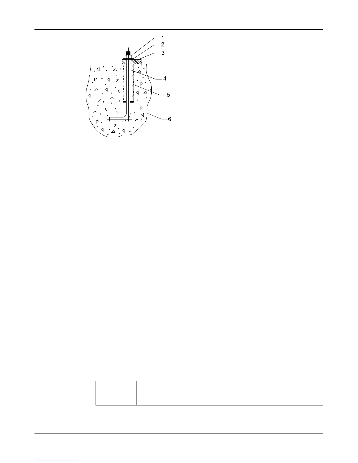
Typical installation
A typical installation has these characteristics:
• Bolts with a pipe sleeve that is two and a half times the size of the bolt diameter embedded
in the concrete
• Properly sized
• Located in accordance with the dimensions given in the example drawing
• Enough space inside the pipe sleeves to allow the final position of the foundation bolts to
align with the holes in the sub-base flange
Page 21
Installation
Model API 3171 Installation, Operation, and Maintenance Manual 19
1. Hex nut
2. Washer
3. Support plate
4. 12.5 mm | 0.5 in. anchor bolt
5. Anchor bolt sleeve
6. Foundation (by customer)
Figure 8: Example of a typical installation
Support plate installation
Install the support plate with a pit cover
If access to the bottom of the pit cover is not possible during the installation process, you must
assemble and install the pump (without the motor), support plate, and pit cover as a unit. You
must install the pit cover perfectly level in order to make sure that the pump remains straight up
and down when installed.
The vapor-proof option includes machined, gasketed fits between the support plate/pit cover
and the pit cover/foundation. You must install these gaskets in order to ensure emissions
performance. Bolt the pit cover to a metal sole plate with a machined surface in order to ensure
an air tight seal.
1. Carefully lower the pit cover onto the foundation bolts.
2. Use as long a level as possible in order to level the pit cover in all directions with shims or
wedges.
3. Hand tighten the anchor bolts. Check the level and re-shim if necessary.
4. Tighten all anchor bolts in a star pattern in order to avoid distorting the pit cover.
5. If access to the bottom side is possible, carefully lower the pump and support plate onto the
pit cover.
6. Install all bolts and hand tighten.
7. Check the level on the support plate and re-shim if necessary.
8. Tighten all bolts in a star pattern in order to avoid distorting the support plate.
Install the support plate without a pit cover
1. Carefully lower the pump and support plate onto the foundation bolts.
2. Level the support plate in all directions using shims and wedges.
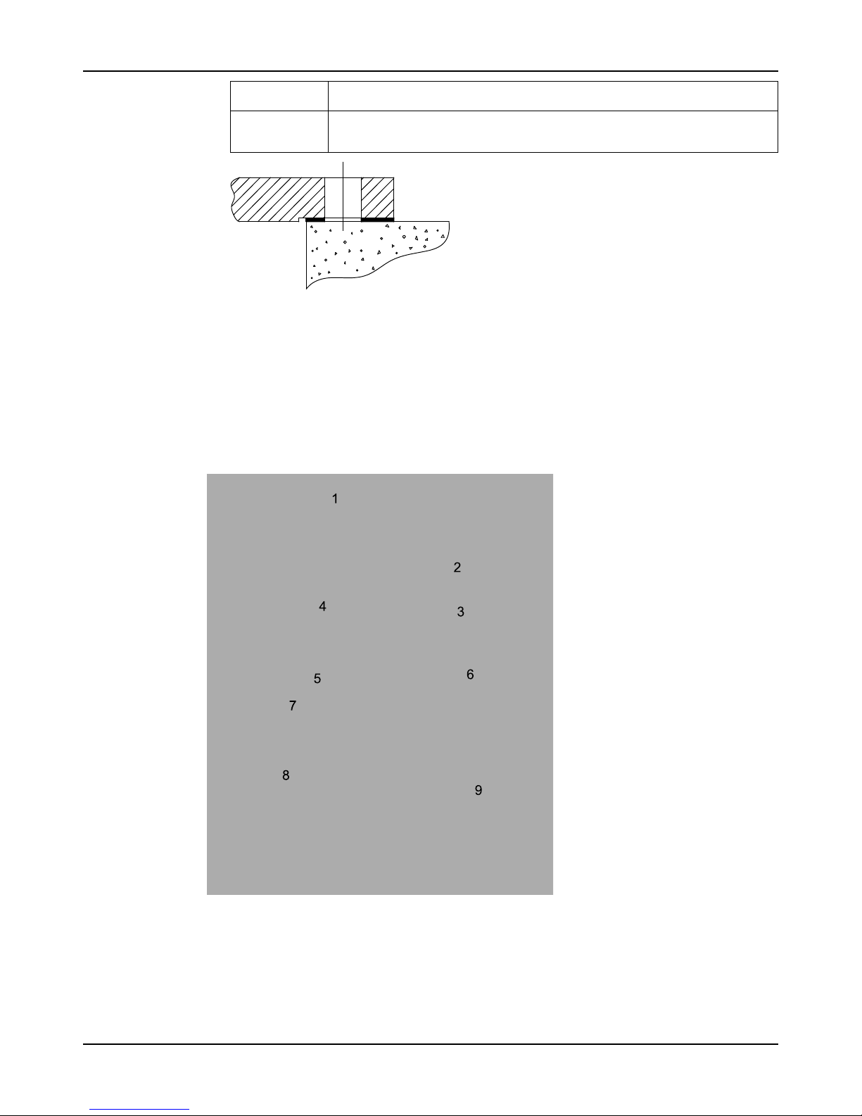
3. If you use the vapor-proof option, then perform one of these actions in order to make sure
that you have an air-tight seal:
Support plate
type
Action
Standard Insert the supplied gasket between the two flanges. Bolt the support plate to a
metal sole plate that has a machined surface.
Page 22
Installation
Model API 3171 Installation, Operation, and Maintenance Manual20
Support plate
type
Action
Tank flange Installthesuppliedgasketbetweenthetwoflanges.Makesurethatthemating
flange on the tank is level. Use gasket material between the flanges in order to
make minor adjustments.
Figure 9: Layout for a standard support plate with the vapor-proof option
4. Hand tighten the anchor bolts. Check the level and re-shim if necessary.
5. Tighten all anchor bolts in a star pattern in order to avoid distorting the support plate.
Stuffing box installation
This pump is a sealless design. Therefore, when temperatures exceed 82°C | 180°F , you must
move the thrust bearing away from the heat source in the pump by adding the upper stuffing
box. Air can then circulate around the bearing in order to keep it cool.
The upper stuffing box is also used to minimize vapor emissions when the pump handles
controlled substances.
1. Motor support
2. Upper stuffing box
3. Gasket
4. Discharge pipe
5. Support plate
6. Gasket
Page 23
Installation
Model API 3171 Installation, Operation, and Maintenance Manual 21
7. 3 in. (76.2 mm) NPT female connection
8. Pit cover
9. Gasket
Install the packed stuffing box
WARNING:
Packed stuffing boxes are not allowed in an ATEX-classified environment.
The stuffing box is packed at the factory. The packing is lubricated by a grease cup supplied
with the pump.
1. Fill the grease cup with any lithium-based #2 grease.
2. Install the grease cup on the tapped opening on the stuffing box.
3. Turn the cap on the grease cup several turns in order to inject the grease into the packing.
4. Hand-tighten the gland nuts.
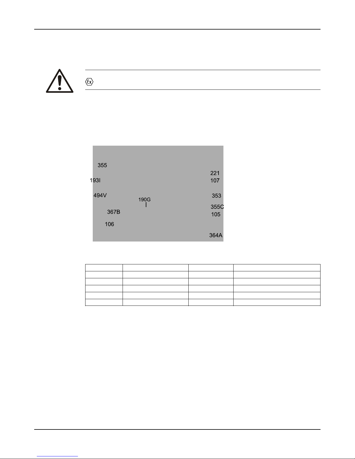
105 Lantern ring 353 Gland stud
106 Packing set 355 Gland nuts
107 Gland 355C Insert nuts
190G Pipe nipple 364A Packed box insert
193I Grease cup 367B Insert gasket
221 Stuffing box support 494V Pipe elbow
Figure 10: Packed stuffing box
Install the pump, driver, and coupling
1. Mount and fasten the pump on the baseplate. Use applicable bolts.
2. Mount the driver on the baseplate. Use applicable bolts and hand tighten.
3. Install the coupling.
See the installation instructions from the coupling manufacturer.
Page 24
Installation
Model API 3171 Installation, Operation, and Maintenance Manual22
Motor installation and coupling alignment
WARNING:
• Misalignment can cause decreased performance, equipment damage, and even catastrophic failure of frame-mounted units leading to serious injury. Proper alignment is the
responsibility of the installer and the user of the unit. Check the alignment of all drive
components prior to operating the unit.
• Follow the coupling installation and operation procedures from the coupling manufactur-
er.
• Failure to disconnect and lock out driver power may result in serious physical injury or
death. Always disconnect and lock out power to the driver before performing any
installation or maintenance tasks.
• Electrical connections must be made by certified electricians in compliance with all
international, national, state, and local rules.
• Refer to driver/coupling/gear manufacturer's installation and operation manuals (IOM)
for specific instructions and recommendations.
NOTICE:
Proper alignment is the responsibility of the installer and the user of the unit. Check the
alignment of frame-mounted units before you operate the unit. Failure to do so can result in
equipment damage or decreased performance.
Install the motor
Use NEMA Vertical C-face motors with this pump. P-base motor adapters and IEC motor
adapters are available as options.
1. Install both coupling halves before you mount the motor.
Refer to the instructions from the coupling manufacturer.
2. Use the lifting lugs on the motor in order to carefully lower the motor onto the pump.
Make sure to align the bolt holes.
3. Before you connect the coupling, wire the motor and check the direction of rotation.
The rotation arrow is on the motor support. The correct rotation is clockwise as you look
down from the drive at the impeller.
Alignment checks
When to perform alignment checks
You must perform alignment checks under these circumstances:
• The process temperature changes.
• The piping changes.
• The pump has been serviced.
Types of alignment checks
Type of check When it is used
Initial alignment (cold alignment)
check
Prior to operation when the pump and the driver are at ambient
temperature.
Final alignment (hot alignment)
check
After operation when the pump and the driver are at operating
temperature.
Initial alignment (cold alignment) checks
When Why
Before you grout the baseplate This ensures that alignment can be accomplished.
After you grout the baseplate This ensures that no changes have occurred during the grouting
process.
After you connect the piping This ensures that pipe strains have not altered the alignment.
Page 25
Installation
Model API 3171 Installation, Operation, and Maintenance Manual 23
Final alignment (hot alignment) checks
When Why
After the first run This ensures correct alignment when both the pump and the driver
are at operating temperature.
Periodically This follows the plant operating procedures.
Permitted indicator values for alignment checks
NOTICE:
The specified permitted reading values are valid only at operating temperature. For cold
settings, other values are permitted. The correct tolerances must be used. Failure to do so can
result in misalignment.
When dial indicators are used to check the final alignment, the pump and drive unit are
correctly aligned when these conditions are true:
• The Total Indicated Reading (T.I.R.) is at 0.05 mm | 0.002 in. or less at operating
temperature.
• The tolerance of the indicator is 0.0127 mm per mm | 0.0005 in. per in. of indicator
separation for the reverse dial indicator or laser method when the pump and driver are at
operating temperature.
Align the coupling
WARNING:
• Failure to disconnect and lock out driver power may result in serious physical injury or
death. Always disconnect and lock out power to the driver before performing any
installation or maintenance tasks.
• Electrical connections must be made by certified electricians in compliance with all
international, national, state, and local rules.
• Refer to driver/coupling manufacturer's installation and operation manuals (IOM) for
specific instructions and recommendations.
• Misalignment can cause decreased performance, equipment damage, and even catastrophic failure of frame-mounted units leading to serious injury. Proper alignment is the
responsibility of the installer and the user of the unit. Check the alignment of all drive
components prior to operating the unit.
• Follow the coupling installation and operation procedures from the coupling manufactur-
er.
• Wheninstalling in a potentially explosive environment, ensure that the motor is
properly certified.
• The coupling used in an ATEX classified environment must be properly certified.
Alignment of the pump and motor is of extreme importance for trouble-free mechanical
operation. Straight-edge alignment by an experienced installer is adequate for most installations. Use dial indicators for disc couplings and applications where alignment to tighter
tolerances is desirable. In these cases, use standard dial indicator procedures.
1. Check for coupling alignment by using either the reverse dial indicator method or laser
alignment tools.
2. Move the motor until you achieve the correct alignment.
Refer to the coupling manufacturer literature for proper alignment criteria.
3. Install discs between the hubs per the manufacturer's directions included with the pump
data package.
4. Tighten all motor bolts.
Float control installation
ITT supplies several different float controls. Refer to the float control installation instructions
provided with the controls for the proper installation procedure. This topic describes the Square
D 9036 Simplex and Square D 9038 Duplex float controls.
Page 26
Installation
Model API 3171 Installation, Operation, and Maintenance Manual24
How float controls work
The on and off levels of the Square D 9036 simplex and the Square D 9038 duplex are
controlled by adjusting the collars (335). As the liquid level rises, the float rises to contact the
upper collar and the upward movement of the float rod causes the mechanical switch inside the
control to close. This completes the circuit to the starter. Operation continues until the liquid
level drops low enough for the float to contact the lower collar. This pulls the rod down, opening
the switch and turning off the pump.
The only difference between the Square D 9036 simplex and the Square D 9038 duplex is in
the operating sequence. For the Square D 9038 duplex, the first pump starts as the water level
rises. This allows the float to contact the upper collar. When the water level drops down and
shuts off the first pump, a lever arm inside the control mechanically switches to the second
pump and it comes on for the next cycle.
If the first pump fails to keep up with demand, or not come on at all, then a continued rise in the
level turns both pumps on. Both pumps run until the low-water level is reached. If both pumps
are unable to keep up with the demand, then an optional high-water alarm switch can be
supplied in the alternator to close a switch if the water level rises past the second pumps on the
level. This switch can be wired into a customer-supplied alarm horn or light.
APEX high level alarm
The APEX high level alarm is an independent device used to sense fluid level and close a
switch that activates a separate alarm. The switch is mounted on a pipe above the support
plate. The pipe must extend into the sump 10 to 15 cm | 4 to 6 in. below the required actuation
point. As the liquid level rises in the pipe, trapped air causes bellows inside the switch to inflate
and trip a microswitch. The switch can then activate a light, horn, relay, solenoid valve, or other
electric device.
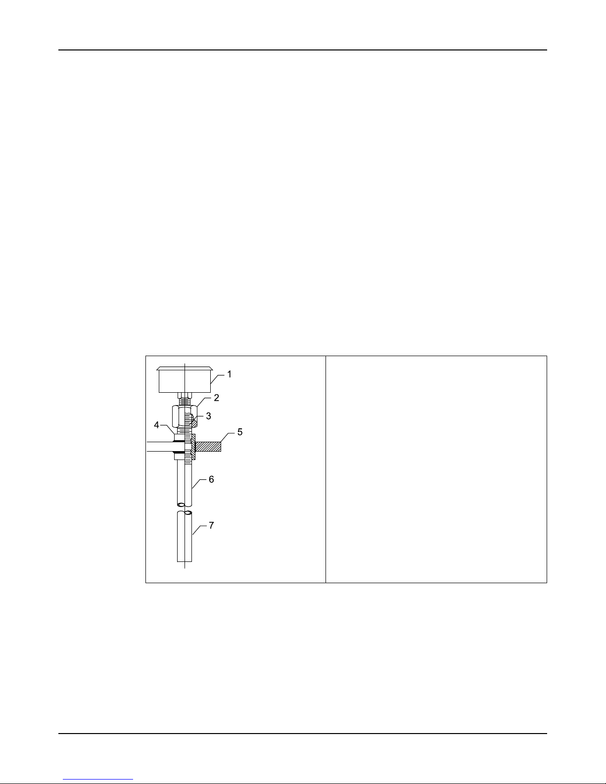
Figure 11: High water alarm
1. High water alarm
2. Reducing adapter, 13.0 mm x 26.0 mm | 0.5 in. x 1.0
in.
3. Nipple, 26.0 mm | 1.0 in.
4. Coupling, 26.0 mm | 1.0 in
5. Pit cover
6. Pipe, 26 mm | 1.0 in, 204 mm | 8.0 in. shorter than
the pump length
7. Cut the pipe 64 mm | 2.5 in. below the required
switch actuation point
Magnetrol displacer-type liquid level switch
The Magnetrol displacer-type liquid level switch is closed by a magnetic seal inside a sealed
tube. Switch operation is controlled by the buoyancy of weighted displacers suspended on a
spring. As liquid level rises, the resulting change in buoyancy moves the spring upwards. The
spring movement causes a magnetic sleeve to attract a pivoted magnet, closing the actuating
switch. Refer to installation guide supplied by the manufacturer for proper installation and
configuration.
Page 27
Installation
Model API 3171 Installation, Operation, and Maintenance Manual 25
Float ball switches
Float balls are individual switches that are used in multiple configurations to control the pump
circuit. The float balls are suspended in the sump to the desired control level. When the fluid
level rises to the float ball, the switch begins to float. The float is either anchored to a pipe or
weighted. This allows the switch to tilt when the fluid continues to rise. When the float tilts, a
switch closes that you can use in order to turn the pump on, activate a high-level alarm, or
control any other electrical device.
Install the Square D 9036 simplex and 9038 duplex float controls
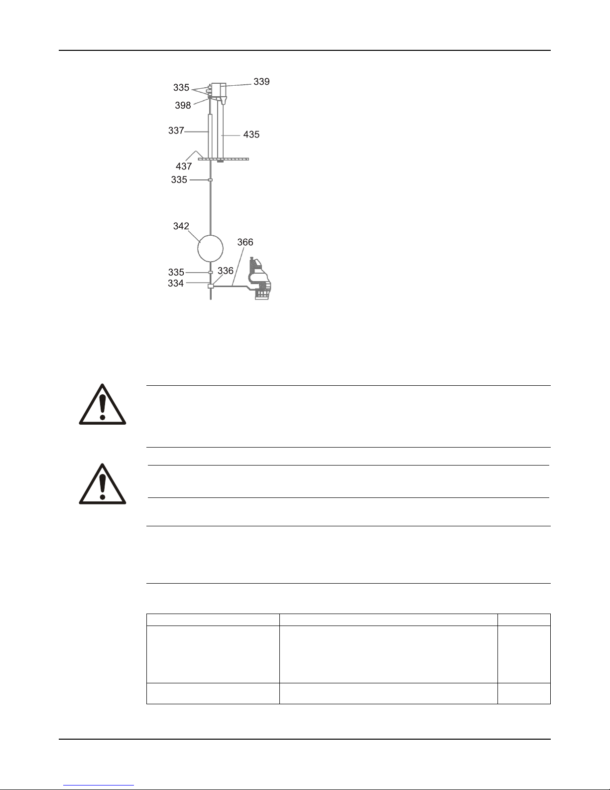
A single float and rod assembly is used with the 9036 float switch on a simplex unit or the 9038
duplex alternator. Refer to the wiring diagram from the manufacturer for the correct wiring of
the switch.
If a pit cover is supplied with the pump, the float switch support pipe (435) and the upper rod
guide (337) are installed by the factory. If the pit cover is supplied by others, you must locate,
drill, and tap the holes before you install the switch.
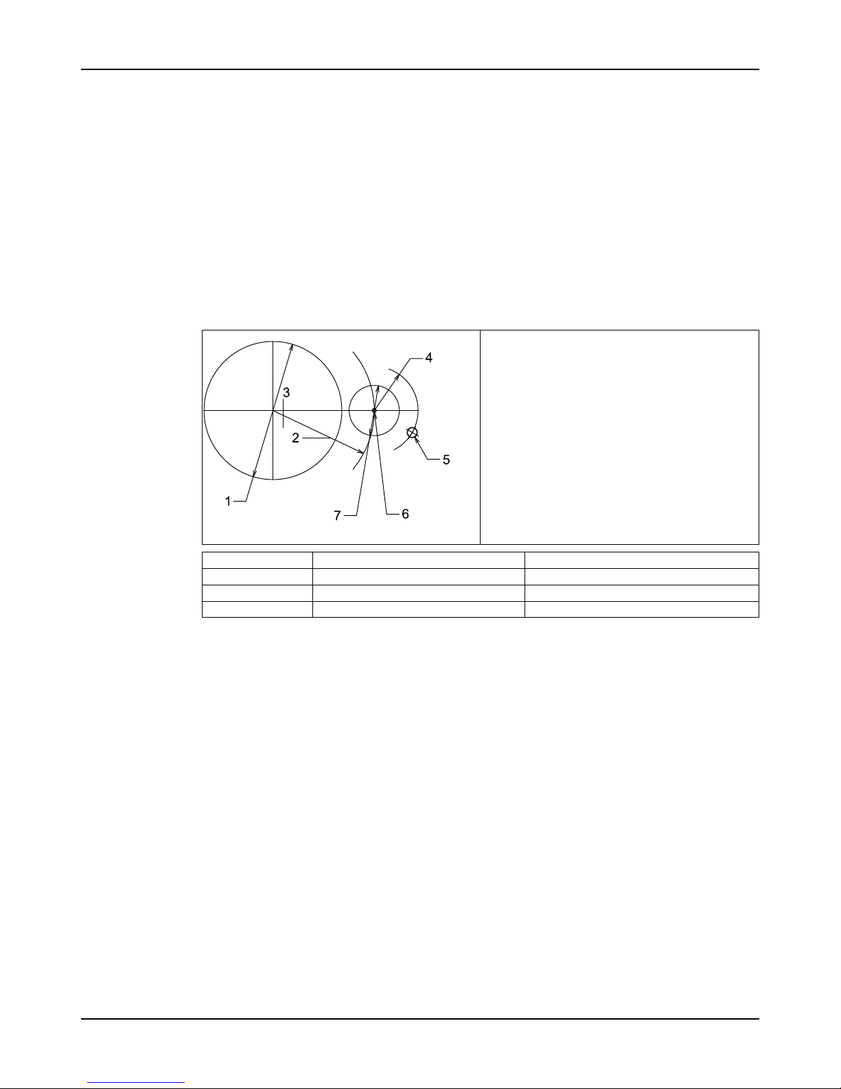
Figure 12: Location of the float, rod, and switch
1. Diameter of the coverplate (A)
2. Radius (B)
3. CL of the pump
4. Radius of 178.0 mm | 7.0 in.
5. 31.8 mm | 1.25 in. NPT float switch NTG
column
6. 9.5 mm | 0.38 in. NPT for the float rod guide
7. 203.0 mm | 8 in. diameter of float (standard)
Number Coverplate diameter (A) Radius (B)
1 559 mm | 22 in. 368mm|14.50in.
2 673 mm | 26.50 in. 419 mm | 16.50 in.
3 787 mm | 31.00 in. 470 mm | 18.50 in.
1. Before you install the pump in the sump, attach the lower guide arm (366) and the float rod
guide (336) to the correct suction cover bolt (based on the layout).
2. Thread the float switch support pipe (435) and the upper rod guide (337) into the pit cover.
3. Attach the float switch bracket (398) to the float switch support pipe.
You can rotate the float switch around the center line of the pump on the radius (B).
4. Install the float rod (334), float (342), and collars (335).
Page 28
Installation
Model API 3171 Installation, Operation, and Maintenance Manual26
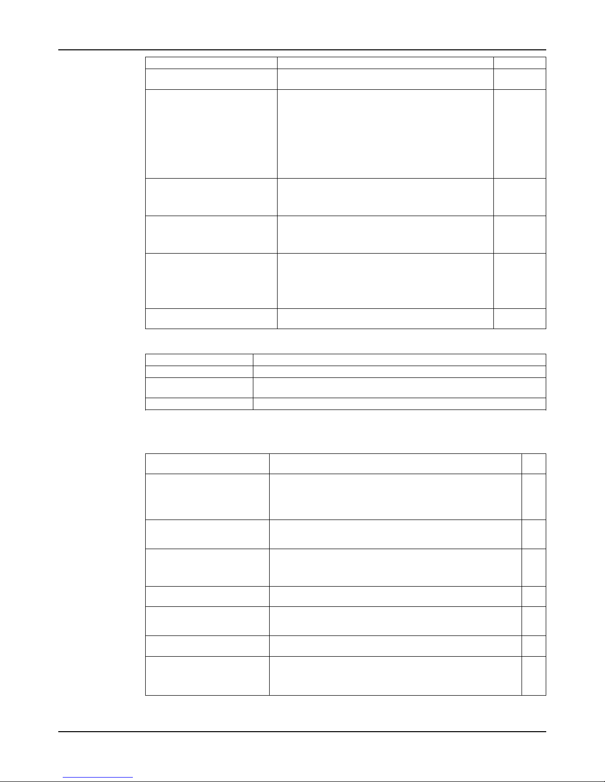
You must maintain the radius (4) between the float switch column and the float.
Figure 13: Radius between float switch column and float
Piping checklists
General piping checklist
Precautions
WARNING:
• Risk of premature failure. Casing deformation can result in misalignment and contact with
rotating parts, causing excess heat generation and sparks. Flange loads from the piping
system, including those from the thermal expansion of the piping, must not exceed the
limits of the pump.
CAUTION:
• Do not move the pump to the pipe. This could make final alignment impossible.
NOTICE:
Vary the capacity with the regulating valve in the discharge line. Never throttle the flow from the
suction side. This action can result in decreased performance, unexpected heat generation,
and equipment damage.
Checklist
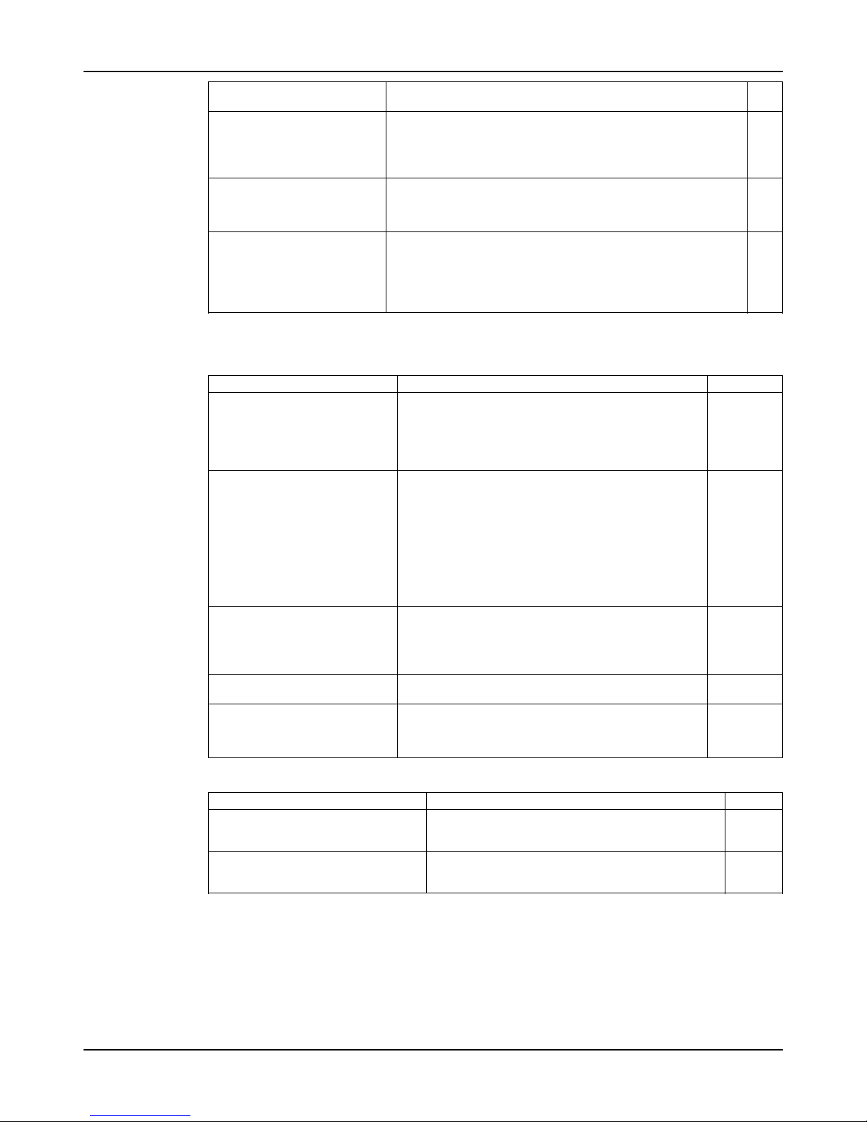
Check Explanation/comment Checked
Check that all piping is supported
independently of, and lined up
naturally with, the pump flange.
This helps to prevent:
• Strain on the pump
• Misalignment between the pump and the drive unit
• Wear on the pump bearings and the coupling
• Wear on the pump bearings, seal, and shafting
Keep the piping as short as possible.
This helps to minimize friction losses.
Page 29
Installation
Model API 3171 Installation, Operation, and Maintenance Manual 27
Check Explanation/comment Checked
Check that only necessary fittings
are used.
This helps to minimize friction losses.
Do not connect the piping to the
pump until:
• The grout for the baseplate
or sub-base becomes hard.
• The grout for the pit cover
becomes hard.
• The hold-down bolts for the
pump and the driver are
tightened.
—
If the pump handles liquids at
elevated temperatures, make
sure that the expansion loops and
joints are properly installed.
This helps to prevent misalignment due to linear expansion of the piping.
Make sure that all piping components, valves and fittings, and
pump branches are clean prior to
assembly.
—
Make sure that the isolation and
check valves are installed in the
discharge line.
Locate the check valve between the isolation valve and
the pump. This will permit inspection of the check valve.
The isolation valve is required for regulation of flow, and
for inspection and maintenance of the pump. The check
valve prevents pump or seal damage due to reverse
flow through the pump when the driver is turned off.
Use cushioning devices. This protects the pump from surges and water hammer
if quick-closing valves are installed in the system.
Alignment criteria for pump flanges
Type Criteria
Axial The flange gasket thickness is ±0.8 mm | 0.03 in.
Parallel Align the flange to be within 0.025 mm/mm to 0.8 mm/mm 0.001 in./in. to
0.03 in./in. of the flange diameter.
Concentric You can easily install the flange bolts by hand.
Suction piping for optional dry pit, outside tank mount, and tailpipe applications
Checklist
Check Explanation/comment Chec
ked
Install an elbow at the pump. Whenever possible, perform these actions:
• Use long radius elbows.
• Move the elbow further from the suction.
• Eliminate unneeded elbows.
Make sure the suction piping is
a larger diameter than the
pump suction.
—
Install separate suction lines
when more than one pump is
operating from the same source
of supply.
—
Make sure that the suction piping contains no air pockets.
—
Make sure that the suction piping slopes upwards toward the
pump.
—
Make sure that all joints are air
tight.
—
Provide a method to prime the
pump.
For outside tank mount and dry pit applications, allow the fluid
level inside the tank or pit to rise above the casing level.
In tailpipe applications, submerge the casing before you start the
pump.
Page 30
Installation
Model API 3171 Installation, Operation, and Maintenance Manual28
Check Explanation/comment Chec
ked
For outside tank mount and dry
pit applications, install an isolation valve in the suction line at
least two pipe diameters from
the suction.
This allows the line to be closed for pump inspection and
maintenance. The isolation valve must be kept fully open during
operation.
Make sure that the entrance to
the suction pipe is kept adequately submerged below the
free liquid surface.
This prevents vortices and air entrainment.
For an outside tank mount application, make sure that a column assembly is installed.
The column assembly allows the fluid that comes through the
lower bushings to flow up through the column and back through
the connection at the top of the column back to the tank.
Connect the pipe at the top of the pump column back to the
source tank in order to prevent fluid from entering the thrust
bearing.
Steam lines
Checklist
Check Explanation/comment Checked
Before you install the pump, become familiar with the location of
the steam lines.
There are three connections above the support plate:
• Two steam connections
• One condensate return connection.
The steam connections are connected to the tops of the
column and discharge jackets.
Determine which method to use in
order to connect the steam lines.
There are two methods you can use in order to connect
the steam lines:
• You can use both steam lines as input for steam
(preferred method).
• You can use one steam line as input for steam,
while the other steam line is used as a feed through
to additional pumps.
Only use this method if absolutely necessary,
because it is difficult to control the steam at
subsequent pumps.
Before you install the pump,
check the fittings for leaks. Use
plant air or high pressure water.
The jackets are hydrotested by the factory at 100 psi
before shipment. However, the tube fittings can become
loose during transit.
If you use air to check for leaks, use a soap solution at
each joint in order to check for air bubbles.
Provide source of steam at 35 psi
and 149°C | 300°F.
Less than ideal conditions require higher pressure
steam in order to keep the correct temperature.
After the pump is brought to temperature for the first time, shut
down the unit temporarily and
readjust the impeller clearance.
Refer to Impeller clearance setting in the Operations
chapter.
Final piping checklist
Check Explanation/comment Checked
Check that the shaft rotates smoothly. Rotate the shaft by hand. Make sure there is no
rubbing that can lead to excess heat generation or
sparks.
Re-check the alignment to make sure
that pipe strain has not caused any
misalignment.
If pipe strain exists, then correct the piping.
Page 31
Commissioning, Startup, Operation, and Shutdown
Model API 3171 Installation, Operation, and Maintenance Manual 29
Commissioning, Startup, Operation, and
Shutdown
Preparation for startup
WARNING:
• Risk of serious physical injury or death. Exceeding any of the pump operating limits (e.g. pressure, temperature, power, etc.) could result in equipment failure, such as explosion,
seizure, or breach of containment. Assure that the system operating conditions are within
the capabilities of the pump.
• Risk of death or serious injury. Leaking fluid can cause fire and/or burns. Ensure all
openings are sealed prior to filling the pump.
• Breach of containment can cause fire, burns, and other serious injury. Failure to follow
these precautions before starting the unit may lead to dangerous operating conditions,
equipment failure, and breach of containment.
• Risk of explosion and serious physical injury. Do not operate pump with blocked system
piping or with suction or discharge valves closed. This can result in rapid heating and
vaporization of pumpage.
• Risk of breach of containment and equipment damage. Ensure the pump operates only
between minimum and maximum rated flows. Operation outside of these limits can cause
high vibration, mechanical seal and/or shaft failure, and/or loss of prime.
• Avoid mechanical seal failure or pump seizure by:
• increasing speed at startup to at least 65% of rated speed within 5 seconds and
• decreasing speed at shutdown from 65% of rated speed to 0 within 5 seconds
WARNING:
• Running a pump without safety devices exposes operators to risk of serious personal
injury or death. Never operate a unit unless appropriate safety devices (guards, etc.) are
properly installed.
• Failure to disconnect and lock out driver power may result in serious physical injury or
death. Always disconnect and lock out power to the driver before performing any
installation or maintenance tasks.
• Electrical connections must be made by certified electricians in compliance with all
international, national, state, and local rules.
• Refer to driver/coupling/gear manufacturer's installation and operation manuals (IOM)
for specific instructions and recommendations.
• Risk of seizure, breach of containment, or explosion. Ensure balance line is installed and
piped back to either the pump suction or suction vessel. This prevents rapid vaporization of
the pumped fluid.
Precautions
NOTICE:
• Verify the driver settings before you start any pump.
• Excessive warm-up rates can cause equipment damage. Ensure the warm-up rate does
not exceed 1.4°C | 2.5°F per minute.
You must follow these precautions before you start the pump:
• Flush and clean the system thoroughly to remove dirt or debris in the pipe system in order
to prevent premature failure at initial startup.
• Bring variable-speed drivers to the rated speed as quickly as possible.
Page 32
Commissioning, Startup, Operation, and Shutdown
Model API 3171 Installation, Operation, and Maintenance Manual30
• Run a new or rebuilt pump at a speed that provides enough flow to flush and cool the
close-running surfaces of the stuffing-box bushing.
• If temperatures of the pumped fluid will exceed 93°C | 200°F, then warm up the pump prior
to operation. Circulate a small amount of fluid through the pump until the casing
temperature is within 38°C | 100°F of the fluid temperature. Accomplish this by flowing fluid
from pump inlet to discharge drain (optionally, the casing vent can be included in warm-up
circuit but not required). Soak for (2) hours at process fluid temperature.
At initial startup, do not adjust the variable-speed drivers or check for speed governor or overspeed trip settings while the variable-speed driver is coupled to the pump. If the settings have
not been verified, then uncouple the unit and refer to instructions supplied by the driver
manufacturer.
Check the rotation - Frame Mounted
WARNING:
• Starting the pump in reverse rotation can result in the contact of metal parts, heat
generation, and breach of containment. Ensure correct driver settings prior to starting any
pump.
• Failure to disconnect and lock out driver power may result in serious physical injury or
death. Always disconnect and lock out power to the driver before performing any
installation or maintenance tasks.
• Electrical connections must be made by certified electricians in compliance with all
international, national, state, and local rules.
• Refer to driver/coupling/gear manufacturer's installation and operation manuals (IOM)
for specific instructions and recommendations.
1. Lock out power to the driver.
2. Make sure that the coupling hubs are fastened securely to the shafts.
3. Make sure that the coupling spacer is removed.
The pump ships with the coupling spacer removed.
4. Unlock power to the driver.
5. Make sure that everyone is clear, and then jog the driver long enough to determine that the
direction of rotation corresponds to the arrow on the bearing housing or close-coupled
frame.
6. Lock out power to the driver.
Lubricate bearings
Thrust bearing lubrication
WARNING:
Risk of explosive hazard and premature failure from sparks and heat generation. Ensure
bearings are properly lubricated prior to startup.
Grease lubrication
Grease-lubricated bearings have zerk fittings installed for each bearing. Bearings are prelubricated at the factory. Unscrew the fittings and confirm there is grease in the line. Replace
the fitting and add grease if necessary.
Pure oil-mist lubrication
The inlet (IN), outlet (OUT), and drain(DRN) ports are stamped on the thrust housing. The
DRN port is located on the bottom of the thrust housing and is below the floorplate on pumps
without a stuffing box. Connect the oil mist system supply to the IN port of the thrust housing.
The outlet for the thrust housing can be connected to the OUT port or DRN port. The
Page 33
Commissioning, Startup, Operation, and Shutdown
Model API 3171 Installation, Operation, and Maintenance Manual 31
recommended oil for the oil mist is an ISO VG 100. See the table for recommended oil mist
airflows. Follow the instructions from the oil mist system supplier. The oil mist system must be
interconnected with the pump so that the pump will shut down if the mist system fails.
Table 3: Recommended oil mist airflows
This data is based on an oil/air ratio of 0.4 cubic inch (0.22 ounce) per hour per cfm.
Frame size Airflow in cfm (l/m)
S/ST 0.10 (2.83)
M/MT 0.16 (4.53)
L 0.22 (6.23)
Flush the steady bearings
There are five 1/4-in. NPT pipe plugs on the standard support plate that you use to connect the
flush lines. Each plug connects with each of the five bearings. Pumps with less than five
bearings still have five plugs, but only the required number are connected to bearings.
1. Remove the plugs from the holes that are connected to flush lines.
2. Connect an external source of clean water to the taps.
The water source must be able to deliver 1 to 2 GPM to each bearing.
3. Turn on the water in order to begin the flush.
Sealed bearings
Sealed bearings have a lip seal above and below the bearing in order to keep grit out of the
bearing. Sealed bearings use a spring-loaded grease cup for lubrication. The bearings are prelubricated at the factory, but the grease cups ship in a separate box in order to prevent shipping
damage. Fill the grease cups with grease and screw the cups into the taps that are connected
to the bearings. Refill the cups with fresh grease as needed. Frequently inspect the grease
cups after startup in order to check usage and establish the best relubrication interval.
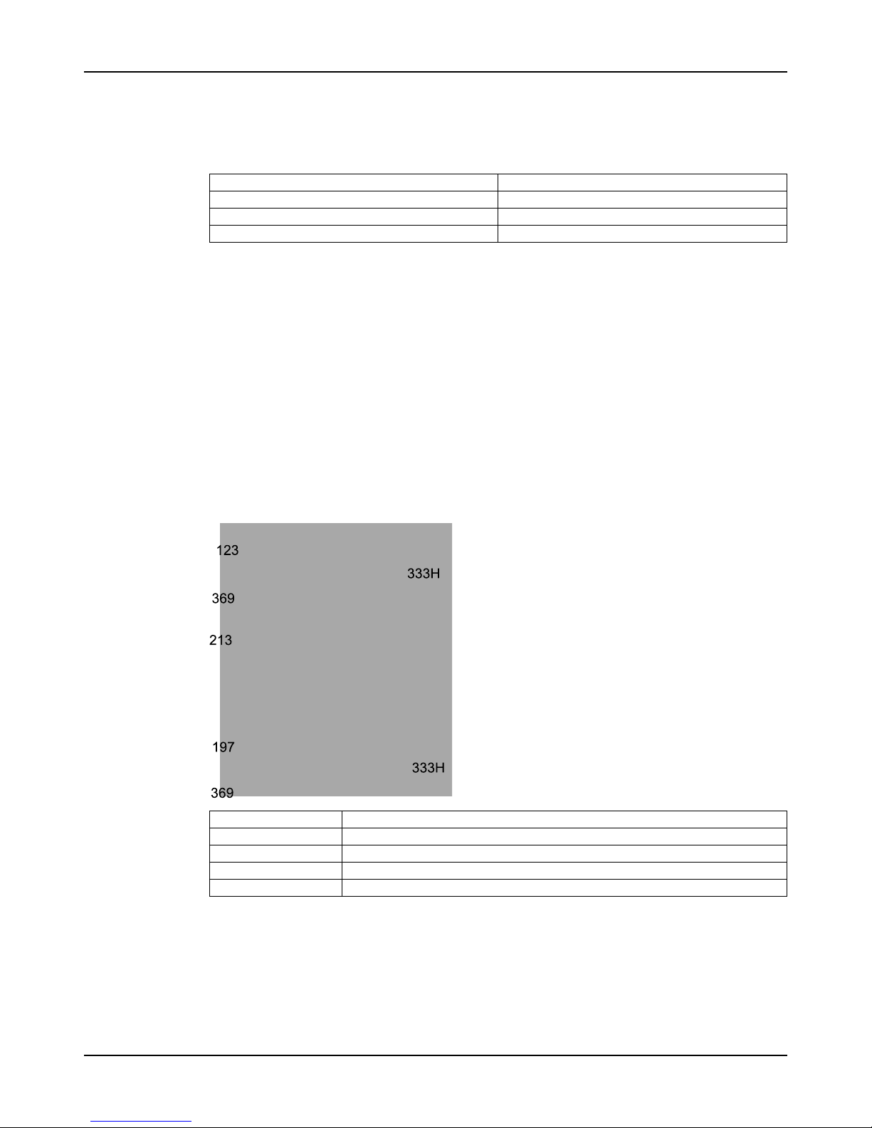
123 Deflector
197 Steady bearings
213 Housing, steady bearings
333H Lipseal
369 Retaining ring, steady bearing
Figure 14: Sealed bearings
Lubricate the sealed bearings with grease cups
For models with grease-lubricated bearings, the spring-operated automatic grease cups are
designed to maintain constant lubrication of the intermediate pump bearings that are fixed to
the vertical pump housing. The center stem protrudes out of the housing when the cup is full
and gradually moves down into the housing as the grease is used. After the wing nut is
Page 34

Commissioning, Startup, Operation, and Shutdown
Model API 3171 Installation, Operation, and Maintenance Manual32
threaded against the stem zerk fitting and the bottom of the wing nut rests on the cap of the
grease cup, then the grease reservoir is empty and you must refill it.
1. Zerk fitting
2. Wing nut
3. Grease reservoir
4. Throttling screw
Figure 15: Lubicate with grease cups
Fill the housing
1. Turn the wing nut clockwise until the center stem is raised all the way and the wing nut
does not turn any further.
2. Fit a pressurized grease gun to the top zerk fitting and pump the grease cup full until a
small amount of grease starts to come out of the side vent of the housing.
3. Unthread the wing nut in order to energize the grease cup. Allow the internal spring
pressure to push grease into the bearing lube line.
4. If the stem immediately recedes into the housing and the bearing has been purged, then
complete these steps:
a) Unthread the top lid in order to remove the top of the grease cup.
b) Inspect the plunger for defects.
If all the grease is found on the reverse (or back side) of the plunger, then it is defective and
must be replaced.
Adjust the flow (preferred method)
1. Unthread the wing nut completely against the zerk fitting of the center stem.
2. Unlock the hex nut of the throttling screw and turn the slotted screw clockwise
approximately one-half turn at a time.
3. Relock the hex nut and monitor the stem movement.
If the grease in the grease cup is completely consumed in 1 to 2 weeks of operation, then the
flow is correct and will maintain the proper amount of grease to the bearings.
Adjust the flow (alternate method)
This method provides a more precise amount of grease to the bearings independent of
changing operating temperatures and surrounding conditions. However, you must have a more
controlled maintenance schedule in order to make sure this is done on a regular basis.
1. Leave the throttling screw locked and open.
2. Back off the wing nut several turns for every 2 to 3 days of operation.
Page 35
Commissioning, Startup, Operation, and Shutdown
Model API 3171 Installation, Operation, and Maintenance Manual 33
Shaft sealing with a mechanical seal
Precautions
WARNING:
The mechanical seal used in an Ex-classified environment must be properly certified.
NOTICE:
• Themechanical seal must have an appropriate seal-flush system. Failure to do so will
result in excess heat generation and seal failure.
• Coolingsystems such as those for bearing lubrication and mechanical-seal systems
must be operating properly to prevent excess heat generation, sparks, and premature
failure.
• Sealingsystems that are not self-purging or self-venting, such as plan 23, require
manual venting prior to operation. Failure to do so will result in excess heat generation and
seal failure.
• Followseal manufacturer's guidelines for proper seal installation procedures.
Shipping
Pumps may be shipped with or without a mechanical seal installed.
Cartridge-type mechanical seals
Cartridge-type mechanical seals are commonly used. Cartridge seals are preset by the seal
manufacturer and require no field settings. Cartridge seals installed by the user require
disengagement of the holding clips prior to operation, allowing the seal to slide into place.
Customers should always check to make sure the clips have been disengaged prior to starting
the pump.
Other mechanical seal types
For other types of mechanical seals, refer to the instructions provided by the seal manufacturer
for installation and setting.
Shaft sealing with a stuffing box
This pump is a sealless design. Therefore, when temperatures exceed 82°C | 180°F, you must
move the thrust bearing away from the heat source in the pump by adding the upper stuffing
box. Air can then circulate around the bearing in order to keep it cool.
The upper stuffing box is also used to minimize vapor emissions when the pump handles
controlled substances.
Steam jacket pumps (molten sulfur construction)
The steam jacketed connections are located on the support plate. The "steam in" line is
connected to an appropriate source of steam, and the "steam out/condensate" connections are
made as dictated by the installation requirements. A suitable trap should be used.
Page 36
Commissioning, Startup, Operation, and Shutdown
Model API 3171 Installation, Operation, and Maintenance Manual34
Pump priming
WARNING:
These pumps are not self priming and must be fully primed at all times during operation.
Loss of prime can lead to excessive heat and severe damage to the pump and seal.
CAUTION:
Do not run the pump dry.
Never start the pump until it has been properly primed. Fully submerge the pump casing prior to
starting the pump.
For dry pit/outside tank mount units:
1. Ensure the suction supply line has adequate fluid head to prime the pump.
2. Slowly open the suction valve.
Install the coupling guard
WARNING:
• Running a pump without safety devices exposes operators to risk of serious personal
injury or death. Never operate a unit unless appropriate safety devices (guards, etc.) are
properly installed.
• Failure to disconnect and lock out driver power may result in serious physical injury or
death. Always disconnect and lock out power to the driver before performing any
installation or maintenance tasks.
• Electrical connections must be made by certified electricians in compliance with all
international, national, state, and local rules.
• Refer to driver/coupling/gear manufacturer's installation and operation manuals (IOM)
for specific instructions and recommendations.
• Thecoupling used in an Ex-classified environment must be properly certified and must
be constructed from a spark resistant material.
This pump is shipped without the coupling guard installed, because the motor and coupling are
also not installed.
1. Wrap the expanded metal shield (501) around the motor support.
2. Install the two guard springs (501L).
Page 37

Commissioning, Startup, Operation, and Shutdown
Model API 3171 Installation, Operation, and Maintenance Manual 35
Start the pump
WARNING:
Risk of equipment damage, seal failure and breach of containment. Ensure all flush and cooling
systems are operating correctly prior to starting pump.
NOTICE:
• Risk of equipment damage due to dry operation. Immediately observe the pressure
gauges. If discharge pressure is not quickly attained, stop the driver immediately, reprime,
and attempt to restart the pump.
• On frame mounted units, ensure that the oil level is correct prior to starting pump. Close
coupled pumps do not have oil lubricated bearings.
NOTICE:
Risk of equipment damage on pure or purge-oil mist-lubricated units. Remove the viewing port
plugs to verify that oil mist is flowing properly. Reinstall the plugs after confirming.
Before you start the pump, you must perform these tasks:
• Open any recirculation or cooling lines.
• Start the external bearing flush, if specified.
• Make sure the shaft rotates freely.
1. Fully close or partially openthe discharge valve, depending on system conditions.
2. Start the driver.
3. Slowly open the discharge valve until the pump reaches the desired flow.
4. Immediately check the pressure gauge to ensure that the pump quickly reaches the correct
discharge pressure.
5. If the pump fails to reach the correct pressure, perform these steps:
a) Stop the driver.
b) Prime the pump again.
c) Restart the driver.
6. Monitor the pump while it is operating:
a) Check the pump for bearing temperature, excessive vibration, and noise.
b) If the pump exceeds normal levels, then shut down the pump immediately and correct
the problem.
A pump can exceed normal levels for several reasons. See Troubleshooting for
information about possible solutions to this problem.
7. Repeat steps 5 and 6 until the pump runs properly.
Page 38
Commissioning, Startup, Operation, and Shutdown
Model API 3171 Installation, Operation, and Maintenance Manual36
Pump operation precautions
General considerations
Operation at reduced capacity
WARNING:
• Risk of breach of containment and equipment damage. Excessive vibration levels can
cause damage to bearings, stuffing box, seal chamber, and/or mechanical seal. Observe
pump for vibration levels, bearing temperature, and excessive noise. If normal levels are
exceeded, shut down and resolve.
• Risk of explosion and serious physical injury. Do not operate pump with blocked system
piping or with suction or discharge valves closed. This can result in rapid heating and
vaporization of pumpage.
• Risk of equipment damage and serious physical injury. Heat build-up can cause rotating
parts to score or seize. Observe pump for excessive heat build-up. If normal levels are
exceeded, shut down and resolve.
NOTICE:
Cavitation can cause damage to the internal surfaces of the pump. Ensure net positive suction
head available (NPSHA) always exceeds NPSH required (NPSH3) as shown on the published
performance curve of the pump.
Operation under freezing conditions
NOTICE:
Do not expose an idle pump to freezing conditions. Drain all liquid that is inside the pump and
any auxiliary equipment. Failure to do so can cause liquid to freeze and damage the pump.
Shut down the pump
WARNING:
Precautions must be taken to prevent physical injury. The pump may handle hazardous and/or
toxic fluids. Proper personal protective equipment should be worn. Pumpage must be handled
and disposed of in conformance with applicable environmental regulations.
1. Slowly close the discharge valve.
2. Shut down and lock out the driver to prevent accidental rotation.
Page 39

Commissioning, Startup, Operation, and Shutdown
Model API 3171 Installation, Operation, and Maintenance Manual 37
Make the final alignment of the pump and driver
WARNING:
• Failure to disconnect and lock out driver power may result in serious physical injury or
death. Always disconnect and lock out power to the driver before performing any
installation or maintenance tasks.
• Electrical connections must be made by certified electricians in compliance with all
international, national, state, and local rules.
• Refer to driver/coupling/gear manufacturer's installation and operation manuals (IOM)
for specific instructions and recommendations.
• Misalignment can cause decreased performance, equipment damage, and even catastrophic failure of frame-mounted units leading to serious injury. Proper alignment is the
responsibility of the installer and the user of the unit. Check the alignment of all drive
components prior to operating the unit.
• Follow the coupling installation and operation procedures from the coupling manufactur-
er.
You must check the final alignment after the pump and driver are at operating temperature. For
initial alignment instructions, see the Installation chapter.
1. Run the unit under actual operating conditions for enough time to bring the pump, driver,
and associated system to operating temperature.
2. Shut down the pump and the driver.
3. Remove the coupling guard.
See Remove the coupling guard in the Maintenance chapter.
4. Check the alignment while the unit is still hot.
See Pump-to-driver alignment in the Installation chapter.
5. Reinstall the coupling guard.
6. Restart the pump and driver.
Page 40

Maintenance
Model API 3171 Installation, Operation, and Maintenance Manual38
Maintenance
Maintenance
Maintenance schedule
Maintenance inspections
A maintenance schedule includes these types of inspections:
• Routine maintenance
• Routine inspections
• Three-month inspections
• Annual inspections
Shorten the inspection intervals appropriately if the pumped fluid is abrasive or corrosive or if
the environment is classified as potentially explosive.
Routine maintenance
Perform these tasks whenever you perform routine maintenance:
• Lubricate the thrust bearings.
• Inspect the seal or packing, if present.
Routine inspections
Perform these tasks whenever you check the pump during routine inspections:
• Check the level and condition of the oil through the sight glass on the bearing frame.
• Check for unusual noise, vibration, and bearing temperatures.
• Check the pump and piping for leaks.
• Analyze the vibration.
• Inspect the discharge pressure.
• Inspect the temperature.
• Check the float controls for the proper setting and operation.
• Check the seal chamber and stuffing box for leaks.
• Ensure that there are no leaks from the mechanical seal.
• Adjust or replace the packing in the stuffing box if you notice excessive leaking.
Three-month inspections
Perform these tasks every three months:
• Check that the foundation bolts are tight.
• Check the packing if the pump has been left idle, and replace as required.
• Check the shaft alignment, and realign as required.
• Check the pump and motor hold down bolts for proper tightness.
Annual inspections
Perform these inspections one time each year:
• Check the pump capacity.
• Check the pump pressure.
• Check the pump power.
If the pump performance does not satisfy your process requirements, and the process
requirements have not changed, then perform these steps:
1. Disassemble the pump.
2. Inspect it.
Page 41
Maintenance
Model API 3171 Installation, Operation, and Maintenance Manual 39
3. Replace worn parts.
Bearing maintenance
These bearing lubrication sections list different temperatures of the pumped fluid. If the
pump is ATEX-certified and the temperature of the pumped fluid exceeds the permitted
temperature values, then consult your ITT representative.
Thrust bearings
The pump comes with a grease-lubricated duplex thrust bearing. The bearing is pre-lubricated
at the factory. Regrease the bearing according to the schedule in the following table.
Table 4: Lubricating intervals in operating hours
Drive-unit size
group
Below 1800 RPM 1800 RPM 3000 RPM 3600 RPM
S/ST 2,000 2,000 1,200 750
M/MT 2,000 1,800 800 450
L 2,000 1,200 — —
Lubricate the bearings after a shutdown period
1. Flush out the bearings and bearing frame with a light oil to remove contaminants.
During flushing, make sure to rotate the shaft slowly by hand.
2. Flush the bearing housing with the proper lubricating oil to ensure oil quality after cleaning.
3. Refer to Reassembly section for proper bearing greasing procedure.
Lubricating-oil requirements
Oil requirements based on temperature
For the majority of operating conditions, bearing temperatures run between 49°C | 120°F and
82°C | 180°F, and you can use an oil of ISO viscosity grade 68 at 38°C | 100°F. If temperatures
exceed 82°C | 180°F, refer to the table for temperature requirements.
Table 5: Oil requirements based on temperature
Temperature Oil requirement
Bearing temperatures exceed 82°C | 180°F Use ISO viscosity grade 100
Pumped-fluid temperatures exceed 177°C | 350°F Use synthetic lubrication.
Lubricating-grease requirements
Precautions
NOTICE:
• Avoid equipment damage or decreased performance. Never mix greases of different
consistencies (NLGI 1 or 3 with NLGI 2) or with different thickeners. For example, never
mix a lithium-based grease with a polyurea based grease. If it is necessary to change the
grease type or consistency, remove the rotor and old grease from the housing before
regreasing.
Bearing temperature
Bearing temperatures are generally about 18°C | 20°F greater than bearing-housing outer surface
temperatures.
This table shows the type of grease required for the operating temperature of the pump.
Bearing temperature Type of grease
-15°C to 110°C | 5°F to 230°F Use a lithium-based mineral-oil grease with a consistency of NLGI 2.
Exceed 177°C | 350°F Useahigh-temperaturegrease.Mineral-oilgreases
should have oxidation stabilizers and a consistency
of NGLI 3.
Page 42
Maintenance
Model API 3171 Installation, Operation, and Maintenance Manual40
Grease recommendations based on temperature
Most pumps use Sunoco 2EP grease. High temperature units that can pump fluids with a temperature
greater than 177°C | 350°F use Mobil SCH32.
This table shows which brand of grease to use when lubricating the pump.
Brand Whentemperatureofpumped
fluid is less than 177°C | 350°F
NLGI consistency 2
When temperature of pumped
fluid is greater than177°C |
350°F NLGI consistency 3
Mobil Mobilux EP2 SCH32
Exxon Unirex N2 Unirex N3
Sunoco Mutipurpose 2EP N/A
SKF LGMT 2 LGMT 3
Regrease the thrust bearing
NOTICE:
Risk of equipment damage. Ensure that the grease container, the greasing device, and the
fittings are clean. Failure to do so can result in impurities entering the bearing housing while
regreasing the bearings.
1. Wipe dirt from the grease fittings.
2. Remove the two grease-relief plugs from the bottom of the frame.
3. Fill both of the grease cavities through the fittings with a recommended grease until the
fresh grease comes out of the relief holes.
4. Make sure that the frame seals are seated in the bearing housing.
If they are not, press them in place with the drains located at the bottom.
5. Reinstall the grease-relief plugs.
6. Wipe off any excess grease.
7. Recheck the alignment.
The bearing temperature usually rises after you regrease due to an excess supply of grease.
Temperatures return to normal in about two to four operating hours as the pump runs and
purges the excess grease from the bearings.
Steady bearings
Check the ID of the casing collar (155) and steady bearing (197) per the dimensions in the
Bearing fits and tolerances table. If the ID is greater than what is allowed, remove the snap ring
(369) and use a suitable hydraulic press in order to remove these items for replacement. If
sealed bearings are provided, then you must also remove the lip seals (333H).
The bearing ID is slightly larger before you press it into the housing in order to allow for ID
shrinkage after you press it in place.
Shaft-seal maintenance
Mechanical-seal maintenance
WARNING:
The mechanical seal used in an Ex-classified environment must be properly certified.
CAUTION:
Running a mechanical seal dry, even for a few seconds, can cause seal failure and physical
injury. Never operate the pump without liquid supplied to the mechanical seal.
Cartridge-type mechanical seals
Cartridge-type mechanical seals are commonly used. Cartridge seals are preset by the seal
manufacturer and require no field settings. Cartridge seals installed by the user require
Page 43
Maintenance
Model API 3171 Installation, Operation, and Maintenance Manual 41
disengagement of the holding clips prior to operation, allowing the seal to slide into place. If the
seal has been installed in the pump by ITT, these clips have already been disengaged.
Other mechanical seal types
For other types of mechanical seals, refer to the instructions provided by the seal manufacturer
for installation and setting.
Reference drawing
The manufacturer supplies a reference drawing with the data package. Keep this drawing for
future use when you perform maintenance and seal adjustments. The seal drawing specifies
the required flush fluid and attachment points.
Before you start the pump
Check the seal and all flush piping.
If the pump is shipped with oil-lubricated seals, keep the seal faces lubricated with oil at all
times.
Packed stuffing-box maintenance
WARNING:
• Packedstuffing boxes are not allowed in an ATEX-classified environment.
• Failure to disconnect and lock out driver power may result in serious physical injury. Never
attempt to replace the packing until the driver is properly locked out.
Lubrication intervals
The lubrication intervals vary and depend upon the temperature and gland tightness. Keep the
grease cup full at all times.
Periodically make several turns on the grease-cup cap while you inject fresh grease into the
stuffing box. Check the pump daily upon initial operation, and extend this interval as required.
NOTICE:
Do not over-tighten the stuffing box. Excessive pressure can wear out packing prematurely and
seriously damage the shaft.
Packing replacement
Replace the packing in this sequence:
1. Three rings of packing
2. Lantern ring
3. Two rings of packing
4. Gland
Page 44
Maintenance
Model API 3171 Installation, Operation, and Maintenance Manual42
Disassembly
Disassembly precautions
WARNING:
• Failure to disconnect and lock out driver power may result in serious physical injury or
death. Always disconnect and lock out power to the driver before performing any
installation or maintenance tasks.
• Electrical connections must be made by certified electricians in compliance with all
international, national, state, and local rules.
• Refer to driver/coupling/gear manufacturer's installation and operation manuals (IOM)
for specific instructions and recommendations.
• Risk of serious personal injury. Applying heat to impellers, propellers, or their retaining
devices can cause trapped liquid to rapidly expand and result in a violent explosion. This
manual clearly identifies accepted methods for disassembling units. These methods must
be adhered to. Never apply heat to aid in their removal unless explicitly stated in this
manual.
• Handling heavy equipment poses a crush hazard. Use caution during handling and wear
appropriate Personal Protective Equipment (PPE, such as steel-toed shoes, gloves, etc.)
at all times.
• Precautions must be taken to prevent physical injury. The pump may handle hazardous
and/or toxic fluids. Proper personal protective equipment should be worn. Pumpage must
be handled and disposed of in conformance with applicable environmental regulations.
• Risk of serious physical injury or death from rapid depressurization. Ensure pump is
isolated from system and pressure is relieved before disassembling pump, removing
plugs, opening vent or drain valves, or disconnecting piping.
• Risk of serious personal injury from exposure to hazardous or toxic liquids. A small amount
of liquid will be present in certain areas like the seal chamber upon disassembly.
CAUTION:
• Avoid injury. Worn pump components can have sharp edges. Wear appropriate gloves
while handling these parts.
Tools required
In order to disassemble the pump, you need these tools:
• Bearing puller
• Brass drift punch
• Cleaning agents and solvents
• Dial indicators
• Feeler gauges
• Hydraulic press
• Induction heater
• Lifting sling
• Micrometer
• Rubber mallet
• Screwdriver
• Snap-ring pliers
• Torque wrench with sockets
• Wrenches
• Lifting eyebolt (dependent on pump / motor size)
Page 45
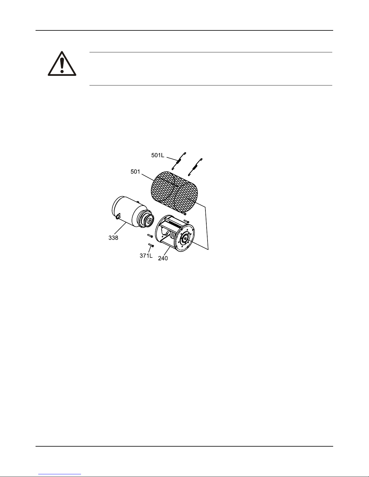
Maintenance
Model API 3171 Installation, Operation, and Maintenance Manual 43
Drain the pump
CAUTION:
• Risk of physical injury. Allow all system and pump components to cool before handling.
• If the pumped fluid is non-conductive, drain and flush the pump with a conductive fluid
under conditions that will not allow for a spark to be released to the atmosphere.
1. Leave the drain valve open.
Do not close the drain valve until the reassembly is complete.
2. Remove the coupling guard.
3. Disconnect the coupling.
Remove the pump from the sump
1. Remove the motor bolts (371).
Figure 16: Motor bolts removal
2. Place the sling on the motor lifting lugs and remove the motor.
3. Remove the support plate anchor bolts.
4. Attach the eyebolts to the support plate.
5. Use properly-sized slings in order to lift the pump from the sump.
Refer to the Installation chapter for the proper handling procedure.
6. Lay the pump horizontally on proper supports where there is sufficient clearance to
disassemble the pump.
Page 46
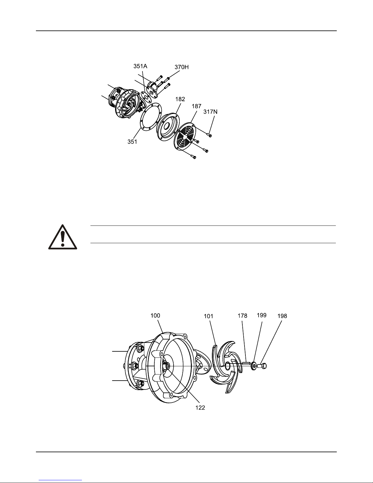
Maintenance
Model API 3171 Installation, Operation, and Maintenance Manual44
7. Remove the bolts (317N) in order to remove the strainer (187).
Figure 17: Remove bolts to remove strainer
8. Remove the suction cover (182).
9. Remove the discharge elbow-casing bolts (370H).
10. Disconnect any steady bearing flush tubing (190).
Remove the impeller
CAUTION:
Risk of physical injury from sharp edges. Wear heavy work gloves when handling impellers.
1. Loosen the set screw at the end of the impeller nut.
2. Loosen and remove the impeller nut.
The impeller nut has left-hand threads.
3. Pull the impeller (101 from the shaft.
Use a spanning-type puller if required.
Figure 18: Remove impeller
Page 47
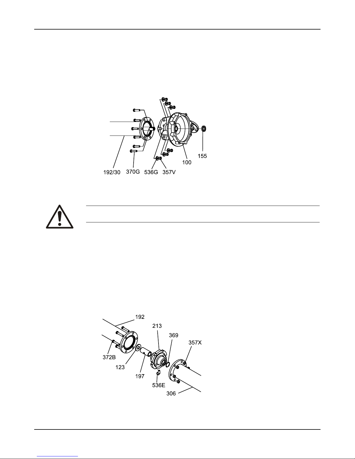
Maintenance
Model API 3171 Installation, Operation, and Maintenance Manual 45
4. Remove the impeller key (178).
Save the key for reassembly unless it is damaged.
5. For L group models only, do the following:
a) Remove the casing (100) to adapter (108) bolts.
b) Remove casing. Do not remove casing collar (155) at this time.
c) Remove the adapter (108) to column bolts.
d) Remove the adapter. Do not remove steady bearing (197) at this time.
Figure 19: Remove adapter
CAUTION:
Two people should handle any shaft over 9 feet long. Improper handling can bend the shaft.
Disassemble the column
1. Remove the column down to the steady bearing housing bolts (372B).
If your pump has no intermediate steady bearings (only one column section), then skip this
step since you do not have any column extension (306) or steady bearing housing (213).
a) Start at the casing end of the pump and remove the column extensions (306), steady
bearing housings (213), and deflectors (123) one at a time. Support the shaft in order to
prevent bending while you remove these sections.
It is not necessary to remove the head column (192). Do not remove the steady
bearings at this time. Refer to inspection procedures prior to removal.
Figure 20: Disassemble the column
Page 48
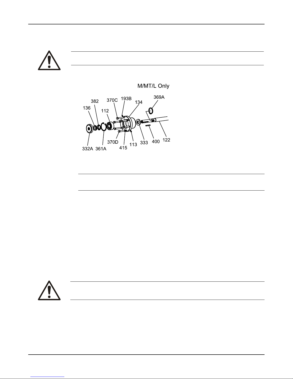
Maintenance
Model API 3171 Installation, Operation, and Maintenance Manual46
2. Remove the pump half coupling hub (233) and key.
3. Remove the locking bolts (370C) and then slide bearing shell (134) assembly with the shaft
out through the motor support (240).
CAUTION:
Two people should handle any shaft over 9 feet long. Improper handling can bend the shaft.
4. Use a screwdriver in order to pry the labyrinth seal (332A) from the bearing shell (134).
NOTICE:
We recommend that you replace the labyrinth seal every time the pump is inspected.
5. Remove the bearing retaining ring (361A).
6. Slide the bearing shell (134) off the bearing and shaft.
7. Remove the locknut (136) and the lockwasher (382).
8. Use a suitable bearing puller in order to remove the bearing (112).
Make sure to save the bearing for inspection.
9. Set the shaft on a table where it is adequately supported.
You do not need to disassemble the pump any further unless you need to replace bad
parts.
Preassembly inspections
Replacement guidelines
Casing check and replacement
WARNING:
Risk of death or serious injury. Leaking fluid can cause fire and/or burns. Inspect and ensure
gasket sealing surfaces are not damaged and repair or replace as necessary.
Inspect the casing for cracks and excessive wear or pitting. Thoroughly clean gasket surfaces
and alignment fits in order to remove rust and debris.
Repair or replace the casing if you notice any of these conditions:
• Localized wear or grooving that is greater than 3.2 mm | 1/8 in. deep
Page 49
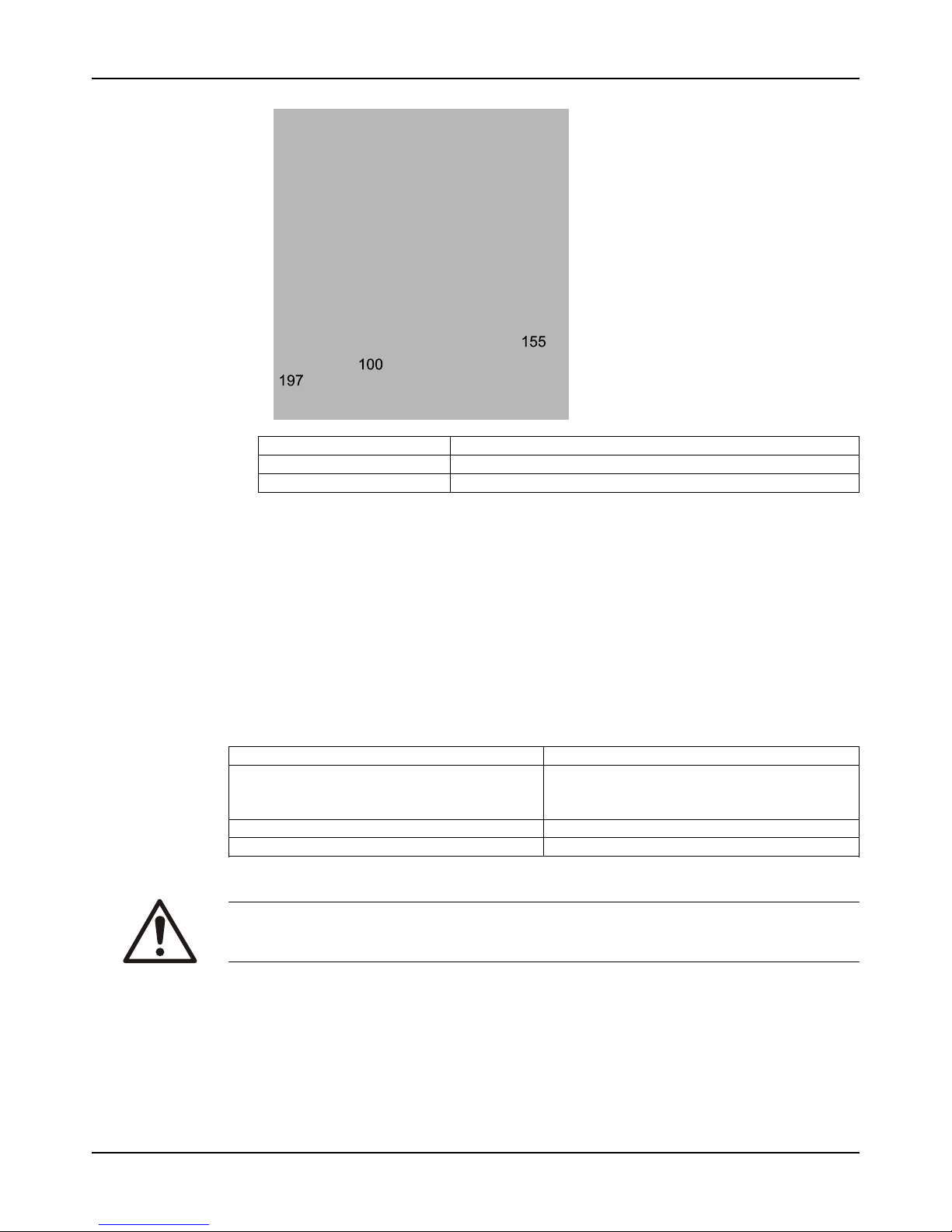
Maintenance
Model API 3171 Installation, Operation, and Maintenance Manual 47
• Pitting that is greater than 3.2 mm | 1/8 in. deep
100 Casing
155 Casing collar
197 Steady bearing
• Check the I.D. of the casing collar (155) and steady bearing (197) per the dimensions in
Bearing fits and tolerances (page 49). If the I.D. is greater than what is allowed, remove
the snap ring (369) and use a suitable hydraulic press to remove these items for
replacement. If sealed bearings have been provided, you must also remove the lip seals
(333H).
• Inspect the casing-to-column connection area for any cracks or excessive corrosion
damage. Replace if any of these conditions exist.
• Irregularities in the casing-gasket seat surface
Casing areas to inspect
Impeller replacement
This table shows the criteria for replacing the impeller:
Impeller parts When to replace
Impeller vanes
• When grooved deeper than 1.6 mm | 1/16 in.,
or
• When worn evenly more than 0.8 mm | 1/32 in.
Pumpout vanes When worn or bent more than 0.8 mm | 1/32 in.
Vane edges When you see cracks, pitting, or corrosion damage
Gaskets, O-rings, and seats replacement
WARNING:
Risk of death or serious injury. Leaking fluid can cause fire and/or burns. Replace all gaskets
and O-rings at each overhaul or disassembly.
Page 50
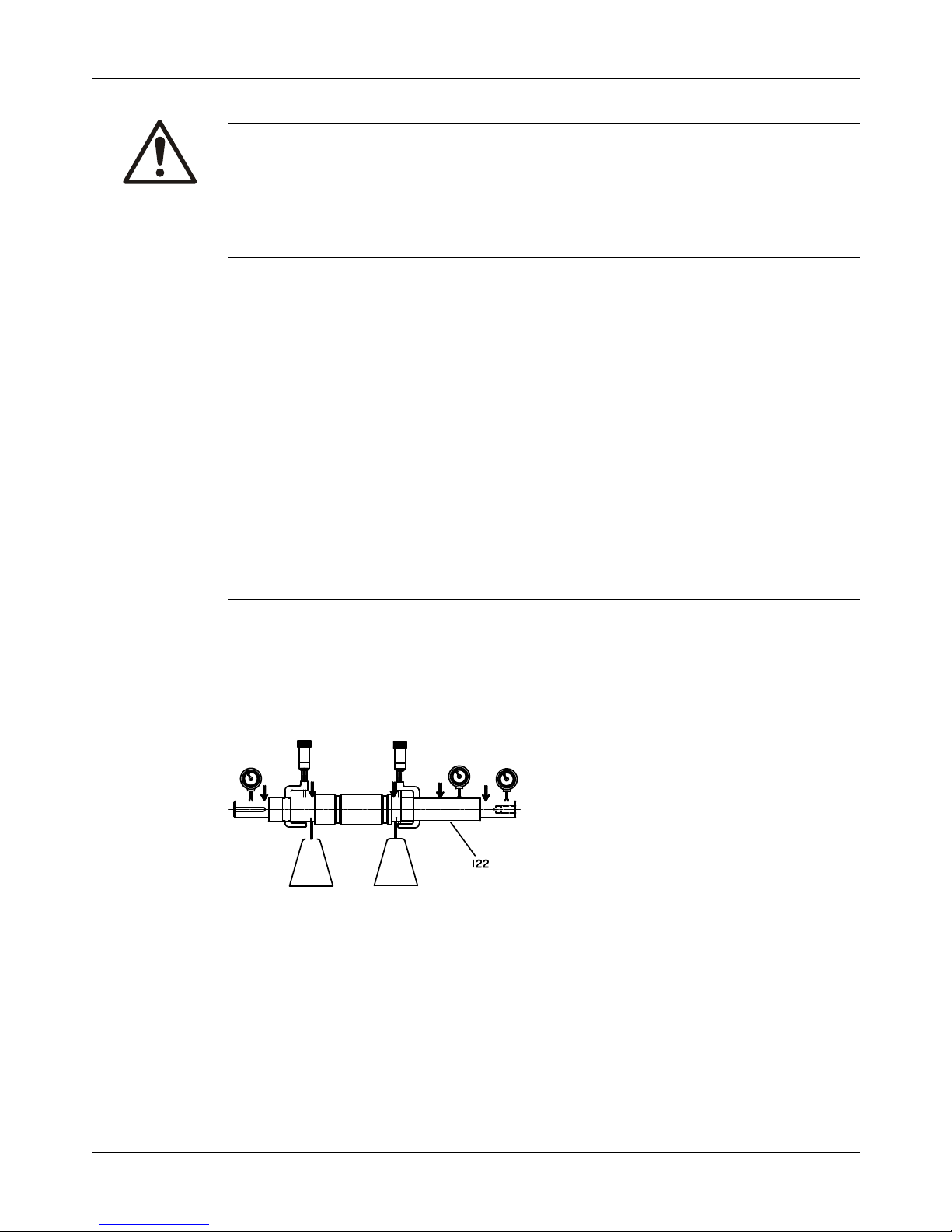
Maintenance
Model API 3171 Installation, Operation, and Maintenance Manual48
Fasteners
WARNING:
Risk of serious personal injury or property damage. Fasteners such as bolts and nuts are
critical to the safe and reliable operation of the product. Ensure appropriate use of fasteners
during installation or reassembly of the unit.
• Use fasteners of the proper size and material only.
• Replace all corroded fasteners.
• Ensure that all fasteners are properly tightened and that there are no missing fasteners.
Column sections
Inspect the column section(s) (306, 192) for any cracks or excessive corrosion damage.
Replace if necessary.
Motor support
Inspect the motor support (240) for any cracks or excessive corrosion damage. Replace if
necessary.
Shaft replacement guidelines
Shaft measurement check
Check the bearing fits of the shaft. If any are outside the tolerances shown in the Bearing fits
and tolerances table, then replace the shaft.
Shaft inspection
Check the shaft straightness. Use "V" blocks or balance rollers to support the shaft on the
bearing fit areas. Replace the shaft if runout exceeds 0.03 mm | 0.001 in.
NOTICE: Do not use shaft centers for the runout check as they may have been damaged
during the removal of the bearings or impeller.
Shaft inspection
Check the shaft surface for damage, especially in areas indicated by the arrows in the following
figure. Replace the shaft if it is damaged beyond reasonable repair.
Figure 21: Shaft inspection
Bearings inspection
Condition of bearings
Do not reuse bearings. The condition of the bearings provides useful information on operating
conditions in the bearing frame.
Checklist
Perform these checks when you inspect the bearings:
• Inspect the bearings for contamination and damage.
• Note any lubricant condition and residue.
Page 51
Maintenance
Model API 3171 Installation, Operation, and Maintenance Manual 49
• Inspect the ball bearings to see if they are loose, rough, or noisy when you rotate them.
• Investigate any bearing damage to determine the cause. If the cause is not normal wear,
correct the issue before you return the pump to service.
• Inspect bearing shell (134) bore according to the dimensions in the Bearing fits and
tolerances - Thrust bearing fits table. Replace if dimensions exceed these values.
• Replace the lower grease seal (133) at every overhaul.
• Visually inspect for cracks and pits. Pay particular attention to the snap ring groove.
Bearing fits and tolerances
Table 6: Steady bearing tolerances
This table references the bearing fits and tolerances according to ISO 286 (ANSI/ABMA Standard 7) in
millimeters | inches.
DescriptionBearing ID (pressed into
place)
Housing bore Running clearance (1/2
diametrical clearance)
S/ST M/MT L S/ST M/MT L S/ST M/MT L
Carbon 28.753–2
8.804 |
1.132–1.
134
41.478–4
1.529 |
1.633–1.
635
57.353–5
7.404 |
2.258–2.
260
41.173–4
1.224 |
1.621–1.
623
53.873–5
3.924 |
2.121–2.
123
76.048–7
6.098 |
2.994–2.
996
0.140–0.
089 |
0.0055–0
.0035
0.152–0.
102 |
0.006–0.
004
0.165–0.
102 |
0.0065–0
.004
Bronze 28.677–2
8.727 |
1.129–1.
131
41.377–4
1.427 |
1.629–1.
631
57.302–5
7.353 |
2.256–2.
258
41.173–4
1.224 |
1.621–1.
623
53.873–5
3.924 |
2.121–2.
123
76.048–7
6.098 |
2.994–2.
996
0.102–1.
051 |
0.004–0.
002
0.102–1.
051 |
0.004–0.
002
0.140–0.
076 |
0.0055–0
.003
Fluted
elastomer
28.600–2
8.702 |
1.126–1.
130
41.326–4
1.453 |
1.627–1.
632
57.226–5
7.328 |
2.253–2.
257
41.173–4
1.224 |
1.621–1.
623
53.873–5
3.924 |
2.121–2.
123
76.048–7
6.098 |
2.994–2.
996
0.089–0.
013 |
0.0035–0
.0005
0.114–0.
025 |
0.0045–0
.001
0.127–0.
102 |
0.005–0.
004
Rulon 28.753–2
8.804 |
1.132–1.
134
41.478–4
1.529 |
1.633–1.
635
57.353–5
7.404 |
2.258–2.
260
- - - 0.140–0.
089 |
0.0055–0
.0035
0.152–0.
102 |
0.006–0.
004
0.165–0.
102 |
0.0065–0
.004
Casing
collar
30.048–3
0.226 |
1.183–1.
190
42.621–4
2.799 |
1.678–1.
685
58.395–5
8.472 |
2.299–2.
306
45.999–4
6.126 |
1.811–1.
816
56.972–5
7.023 |
2.243–2.
245
82.372–8
2.423 |
3.243–3.
245
0.851–0.
737 |
0.0335–0
.029
0.787–0.
673 |
0.031–0.
0265
0.737–0.
622 |
0.029–0.
0245
Table 7: Thrust bearing fits
Group Shaft OD Shell ID
S/ST 25.0139/25.0038) |
0.9848/0.9844
62.0166/61.9989 |
2.4416/2.4409
M/MT 40.0177/40.0025|
1.5755/1.5749
90.0227/89.9998 |
3.5442/3.5433
L 55.0164/55.0037 |
2.1660/2.1655
120.0226/119.9896 |
4.7253/4.7240
Shaft runout tolerances
The following shaft runout tolerances apply to all size groups:
• Coupling end: 0.051 mm | 0.002 in.
• Shaft body: 0.0005 in./ft.
• Impeller end: 0.127 mm | 0.005 in.
Reassembly
Assemble the column and support plate
1. If you use the optional stuffing box, then attach the stuffing box (221) to support plate (189)
with bolts (370L).
2. Attach the motor support (240):
Page 52
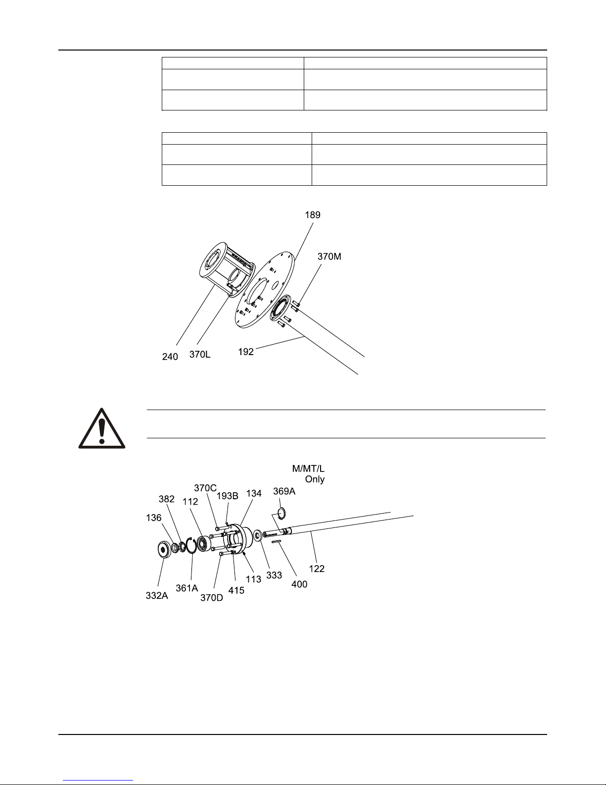
Maintenance
Model API 3171 Installation, Operation, and Maintenance Manual50
If ... Then...
You use the stuffing box Attach the motor support (240) to the stuffing box with bolts
(370J).
You do not use the stuffing box Attach the motor support (240) to the support plate (189) with
bolts (370J).
3. Attach the head column (192):
If... Then...
You use the stuffing box Attach the head column (192) to the stuffing box with bolts
(370M).
You do not use the stuffing box Attach the head column (192) to the motor support with bolts
(370M).
Make sure that the vent holes are closer to the motor support.
Assemble the rotating element
CAUTION:
Two people should handle any shaft over 9 feet long. Improper handling can bend the shaft.
1. For all groups except S/ST, install the retaining ring (369A) on the shaft (122).
2. Install the thrust bearing (112) on the shaft.
There are several methods that you can use in order to install bearings. The recommended
method is to use an induction heater that heats as well as demagnetizes the bearing.
Page 53
Maintenance
Model API 3171 Installation, Operation, and Maintenance Manual 51
CAUTION:
Risk of physical injury from hot bearings. Wear insulated gloves when using a bearing heater.
3. Install the lockwasher (382) on the shaft (122). Make sure that the tang of lockwasher is in
the keyway of the shaft.
4. Thread the locknut (136) onto the shaft and tighten the locknut until it is snug.
5. Bend any tang of the lockwasher into one of the slots on the locknut. Tighten the locknut if
necessary to align a lockwasher tab with a locknut slot.
6. Press the grease seal (333) into the bearing shell (134).
7. Slide the bearing shell onto the pump-end of the shaft and over the bearing.
8. Insert the retaining ring (361A) in the bearing shell groove. Make sure to keep the flat side
against the bearing.
9. Slide the labyrinth seal (332A) over the coupling-end of the shaft into the bearing shell until
it is flush.
10. With the support plate in a vertical position, slide the shaft horizontally through the motor
support. Support the shaft and column with suitable stands.
11. Install the hold-down bolts (370C) and jacking bolts (370D) with jam nuts (415).
Assemble the column
If intermediate steady bearings are required, then you need additional column extensions (306)
and steady bearing housings (213).
1. Prepare the steady bearing housing assemblies, if applicable.
You do not need to precisely center the steady bearing, and the holes in the bearing do not
need to line up with the holes in the housing. A recessed area inside the housing (213)
allows lubricants to find the opening in the bearing.
a) Remove the snap ring (369), if applicable.
b) Use a hydraulic press in order to press out the old steady bearing (197).
c) Press in the new steady bearing.
A snap ring (369) is no longer required due to the fits. If your pump has a snap ring,
then it is not necessary to reinstall it. However, the snap ring is still required on sealed
bearings.
2. Slide the casing assembly onto the shaft and seat the casing flange against the column
flange.
Make sure the discharge nozzle is aligned with the discharge pipe hole in the support plate.
3. Install the bolts (371G).
Assemble the impeller, suction cover, and strainer
1. Add a film of oil to the shaft and place the impeller key (178) and impeller (101) on the
shaft.
2. Check that all of the bearing shell bolts (370C and 370D) are completely backed off.
3. Install the impeller washer (199) and impeller screw (198).
When you tighten the impeller screw, the impeller will be seated on the shaft. The impeller
screw has a nylon insert to lock it in place. Do not exceed these torque values when you
tighten the impeller screw:
Group Torque value
S/ST 56 Nm | 500 in-lbs
M/MT and L 102Nm |900in-lbs
4. Install the suction cover gasket (351), suction cover (182), and strainer (187) with bolts
(317N).
Alloy strainers have extra-heavy spacer washers (533) between the strainer and the
suction cover. If the unit is supplied with a lower-float control guide arm (366), then use an
extra-long bolt in this hole.
Page 54

Maintenance
Model API 3171 Installation, Operation, and Maintenance Manual52
5. Check the axial travel of the impeller.
If the travel is less than 0.762 mm | 0.030 in., then add extra gaskets (351) in order to
obtain the minimum travel.
6. Install the discharge elbow gasket (351A) and the discharge elbow (315) using bolts
(370H).
Accurate alignment of the elbow is critical in order to make sure that there is no obstruction
to the flow through the connection.
7. Install the discharge pipe (195), pipe nuts (242), and flange (195S, if used).
Make sure that the pipe nuts are tight and that there is no strain on the pump.
8. Rotate the shaft by hand in order to make sure that there is no binding.
9. Connect all auxiliary piping.
10. Replace the pump half coupling hub (233) and lubricate the pump bearings.
Page 55
Troubleshooting
Model API 3171 Installation, Operation, and Maintenance Manual 53
Troubleshooting
Troubleshooting
Operation troubleshooting
Symptom Cause Remedy
The pump is not delivering
liquid.
The pump is not primed. Make sure the pit is filled with liquid above the
casing. On dry pit units, the casing and suction
pipe must be completely filled.
The discharge head it too high. Check the total head, particularly friction loss.
The motor speed is too low. Check the motor speed.
The suction line is clogged. Remove the obstructions.
The impeller, discharge pipe, or strainer is
clogged.
Remove obstructions or back-flush the pump.
The shaft is rotating in the wrong direction. Change the rotation. The rotation must match the
arrow on the bearing housing or pump casing.
The suction lift is too high. Shorten the suction pipe.
The amount of available NPSH is not suffi-
cient.
Check the amount of NPSH available and required
and adjust accordingly.
The pump is not producing
the rated flow or head.
The shaft is rotating in the wrong direction. Change the rotation. The rotation must match the
arrow on the bearing housing or pump casing.
The discharge head is higher than expected. Check the total head, particularly friction loss.
The impeller, discharge pipe, or strainer is
clogged.
Remove obstructions or back-flush the pump.
The motor speed is too low. Check the motor speed.
The suction line is clogged. Remove the obstructions.
The suction lift is too high. Shorten the suction pipe.
The impeller is worn or broken. Inspect and replace the impeller if necessary.
The suction line has air or vapor pockets. Rearrange the piping in order to eliminate air
pockets.
The amount of available NPSH is not suffi-
cient.
Check the amount of NPSH available and required
and adjust accordingly.
The pump starts and then
stops pumping.
The pump is not primed. Re-prime the pump and check that the pump and
suction line are full of liquid.
The float controls are not adjusted properly. Check the float controls.
The strainer is clogged. Check the sump for large items that the pump may
be picking up. Check if the bearings are running
hot.
The suction line has air or vapor pockets. Rearrange the piping in order to eliminate air
pockets.
The suction line has an air leak. Repair the leak.
The bearings are running
hot.
The pump and driver are not aligned properly. Realign the pump and driver.
There is not sufficient lubrication. Check the lubricant for suitability and level.
The lubrication was not cooled properly. Check the cooling system.
The pump is noisy or vibrates.
The pump and driver are not aligned properly. Realign the pump and driver.
The impeller is partly clogged. Back-flush the pump in order to clean the impeller.
The impeller or shaft is broken or bent. Replace the impeller or shaft as necessary.
The foundation is not rigid. Tighten the hold-down bolts of the pump and
motor. Make sure that the base plate is properly
grouted without voids or air pockets.
The bearings are worn. Replace the bearings.
Rotating parts are loose, broken, or rubbing
against each other.
Replace parts as necessary.
The suction or discharge piping is not an-
chored or properly supported.
Anchor the suction or discharge piping as neces-
sary according to recommendations in the Hy-
draulic Institute Standards Manual.
The pump is cavitating. Locate and correct the system problem.
Page 56
Troubleshooting
Model API 3171 Installation, Operation, and Maintenance Manual54
Symptom Cause Remedy
The motor requires excessive power.
The discharge head has dropped below the
rated point and is pumping too much liquid.
Install a throttle valve. If this does not help, then
trim the impeller diameter. If this does not help,
then contact your ITT representative.
The liquid is heavier than expected. Check the specific gravity and viscosity.
Rotating parts are rubbing against each other. Check the parts that are wearing for proper
clearances.
The motor speed is too high. Checkthemotorspeed.
The impeller clearance is too tight. Adjust the impellerclearance.
Assembly troubleshooting
Table 8: Troubleshooting procedure
Symptom Cause Remedy
There is excessive shaft end play. Theinternalclearanceofthebearingsis
excessive.
Replace the bearings with a bearing
of the correct type.
The thrust-bearing end cover is loose. Tighten the screws.
There are too many shims under the thrust
bearing end cover.
Remove the individual shims to ob-
tain the proper thickness.
The runout for the shaft is excessive. The shaft is bent. Replace the shaft.
The runout for the bearing-frame flange is
excessive.
The shaft is bent. Replace the shaft.
The flange of the bearing frame is distorted. Replace the bearing-frame flange.
The runout for the seal-chamber cover is
excessive.
The seal-chamber cover is improperly seated on the frame.
Replace or re-machine the seal-
chamber cover.
There is corrosion or wear on the seal-
chamber cover.
Replace the seal-chamber cover.
The runout for the impeller wear ring is
excessive.
The shaft is bent. Replace the shaft.
The wear ring was machined improperly. Replace or re-machine the impeller.
Page 57
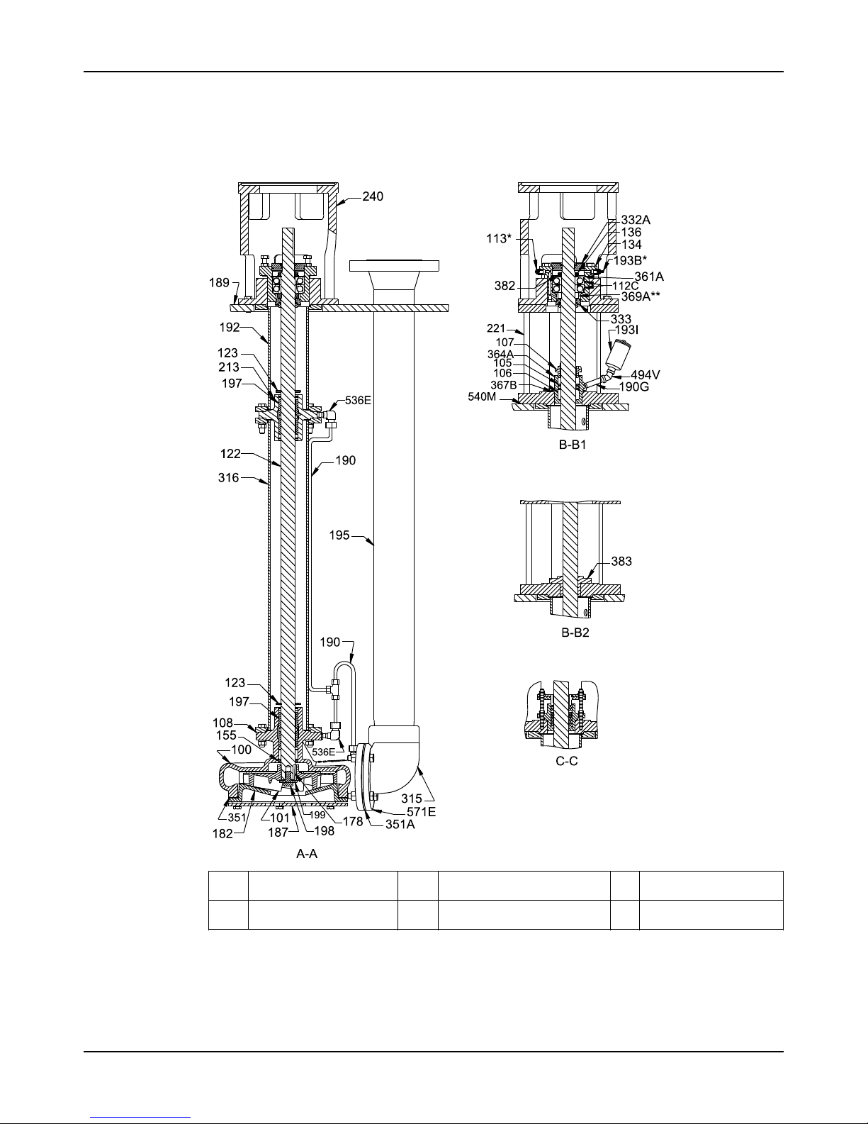
Parts Listings and Cross-Sectionals
Model API 3171 Installation, Operation, and Maintenance Manual 55
Parts Listings and Cross-Sectionals
Cross-sectional diagram
A-A Main pump components B-B2 Upper stuffing box with me-
chanical seal
* Grease lube only
B-B1 Upper stuffing box with
packing
C-C Detail of B-B1 ** M and MT groups only
Page 58
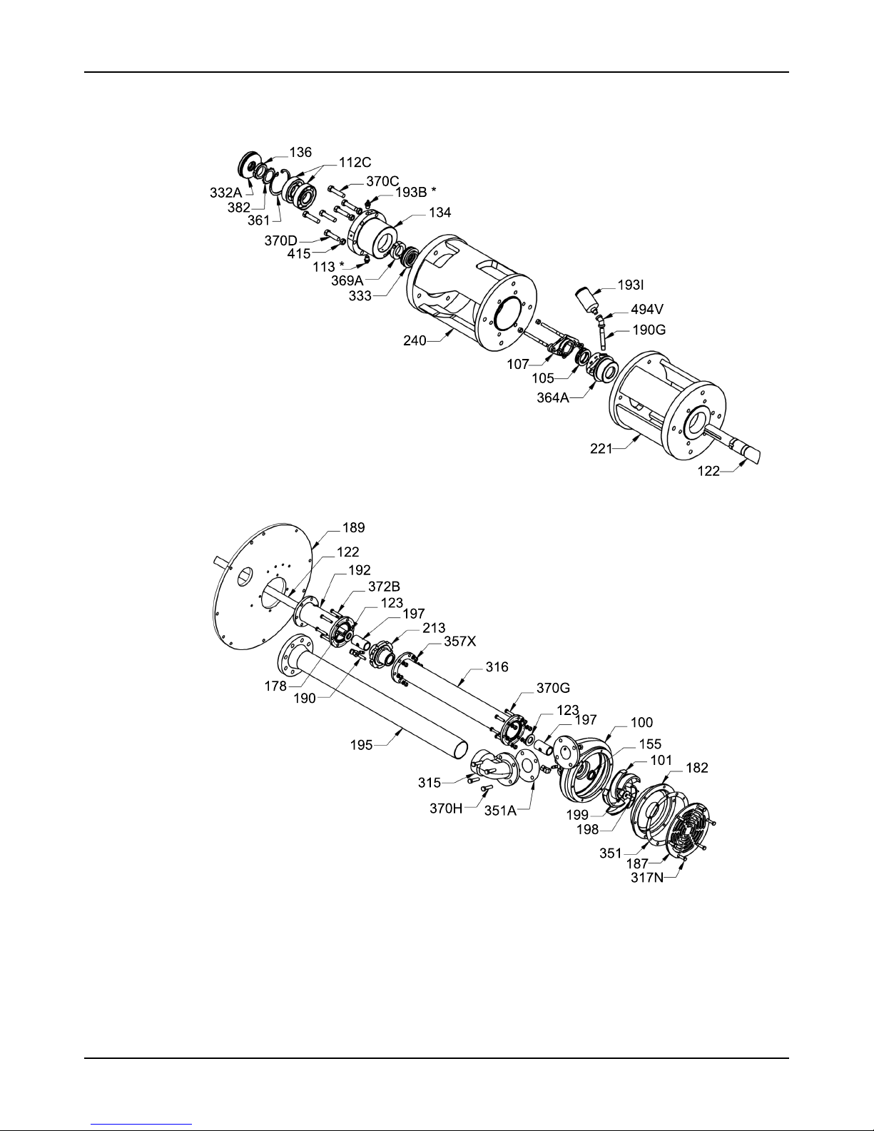
Parts Listings and Cross-Sectionals
Model API 3171 Installation, Operation, and Maintenance Manual56
Dimensional drawings
Exploded view A
Exploded view B
Page 59
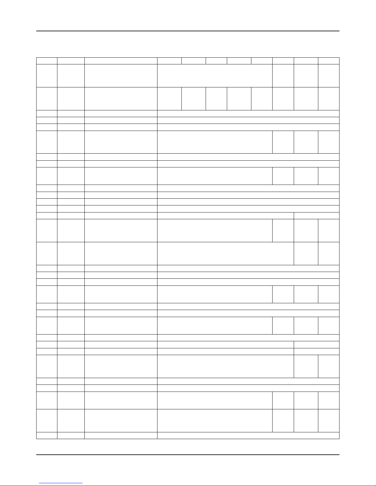
Parts Listings and Cross-Sectionals
Model API 3171 Installation, Operation, and Maintenance Manual 57
Parts list
Table 9: Parts list with materials of construction
Item Quantity Partname S-1/S-4 S-3 S-5 S-6 S-8 A-8 D-1 D-2
100 1 Casing A216 WCB (1212)
A743
CF8M
(1203)
A890
Grade
4A
(1360)
A890
Grade
5A
(1361)
101 1 Impeller
A536 6545-12
(1018)
A436
Type 2
(1007)
A216
WCB
(1212)
A487
CA6NM
(1234)
A743
CF8M
(1203)
A743
CF8M
(1203)
A890
Grade
4A
(1360)
A890
Grade
5A
(1361)
105 1 Lanternring As specified
106 Set Packing As specified
107 1 Gland 1000 or 1203
108 1
Casing from adapter (L group
only)
A216 WCB (1212)
A743
CF8M
(1203)
A890
Grade
4A
(1360)
A890
Grade
5A
(1361)
112C 2 Thrust bearing Angular contact with machined brass cage
113 1 Greaserelief Steel
122 1 Shaft A582 S41600 (2218)
A276
S31600
(2216)
A276
S31803
(2478)
A479
S32750
(3273)
123 1 Deflector Neoprene
134 1 Bearingshell A216 WCB (1212)
136 1 Bearinglocknut Steel
155 1 Casingbushing Carbon-filledPTFE(PTFE)
178 1 Impellerkey 2229 2248
182 1 Suctioncover A216 WCB (1212)
A743
CF8M
(1203)
A890
Grade
4A
(1360)
A890
Grade
5A
(1361)
187 1 Strainer 3211
A890
Grade
4A
(1360)
A890
Grade
5A
(1361)
189 1 Supportplate 3201
190 1 Flushtubing Asspecified
190G 1 Pipenipple Steel
192 1 Headcolumn A53 Grade F (6501)
A312
316L
(6545)
A790
S31803
(6762)
A790
S32750
(6682)
193B 1 Grease fitting Steel
193I 1 Grease cup Steel
195 1 Dischargepipe A53 Grade F (6501)
A312
316L
(6545)
A790
S31803
(6762)
A790
S32750
(6682)
197 1 Steadybearings Carbon or as specified
198 1 Impellerscrew 2229 2248
199 1 Impellerwasher 2229 2248
213 1 Steadybearinghousing A216 WCB (1212)
A890
Grade
4A
(1360)
A890
Grade
5A
(1361)
221 1 Stuffingboxsupport 1000
240 1 Motorsupport 1000
306 1 Columnextension A53 Grade F (6501)
A312
316L
(6545)
A790
S31803
(6762)
A790
S32750
(6682)
315 1 Dischargeelbow A216 WCB (1212)
A351
CF3M
(1296)
A890
Grade
4A
(1360)
A890
Grade
5A
(1361)
332A 1 Labyrinth seal, upper Bronze INPRO
Page 60
Parts Listings and Cross-Sectionals
Model API 3171 Installation, Operation, and Maintenance Manual58
Item Quantity Partname S-1/S-4 S-3 S-5 S-6 S-8 A-8 D-1 D-2
333 1 Labyrinthseal,lower Bronze INPRO
351 1
Gasket, suction cover to casing
Nitrile acrylic
351A 1
Gasket, discharge elbow to
casing
Nitrile acrylic
361A 1 Retaining ring, thrust bearing Steel
364A 1 Stuffing box 1203
367B 1 Gasket, stuffing box insert Nitrile acrylic
369A 1 Bearing collar Steel
370C 3 Clamp bolt 2210
370D 3 Jack bolt 2210
370G 6 Bolt,column-to-casing A193 B8M (2272) 2248
370H 4 Bolt, elbow-to-casing A193 B8M (2272) 2248
370M 6
Bolt, head column-to-motor
support
A193 B8M (2272)
372B 6
Bolt, head column-to-column
extension
As specified
382 1 Bearinglockwasher Steel
383 1 Mechanicalseal As specified
415 3 Jamnutforjackbolt 2210
494V 1 Pipe elbow 1000
536E 1 Tube fitting, steady bearing As specified
540M 1 Gasket, upper stuffing box As specified
543E 1 Tube fitting, support plate As specified
571E 1
Discharge elbow flange (L
group only)
A216 WCB (1212)
A351
CF3M
(1296)
A890 Grade 4A
(1360)
1
The quantity depends on pump length.
Table 10: Material code cross reference
Goulds code ASTM number
1000 A48 CL25B cast iron
1007 A436 Type 2 Ni-Resist
1018 A536-84 60-42-10 ductile iron
1203 A743 CF8M 316 stainless
1212 A216 WCB carbon steel
1234 A487 GR CA-6NM Class A
1296 A351 GR CF-3M
1360 A890 Grade 4A 22Cr-5Ni-Mo-N
1361 A890 Grade 5A 25Cr-7Ni-Mo-N
2210 A108 Gr1211 carbon steel
2216 A276 316 stainless ground and polished
2218 A582 Type 416 stainless steel
2229 A276-91A stainless
2248 B574 C-276 Hastelloy C
2272 A193 B8M AISI Grade 316 alloy steel
2478 A479 Type S 31083
3201 A283 Grade D carbon steel plate
3211 A240 316 steel plate
3273 A479 Alloy 2507 (annealed) turned, ground, and polished
6501 A53 Type F carbon steel schedule 40 pipe
6545 A312 316L stainless steel schedule 40 pipe
6682 A790 Alloy 2507 schedule 40 pipe
6762 A790 GR S 31803 stainless steel welded pipe
Page 61

Other Relevant Documentation or Manuals
Model API 3171 Installation, Operation, and Maintenance Manual 59
Other Relevant Documentation or Manuals
Other Relevant Documentation or Manuals
For additional documentation
For any other relevant documentation or manuals, contact your ITT representative.
Page 62
Local ITT Contacts
Model API 3171 Installation, Operation, and Maintenance Manual60
Local ITT Contacts
Regional offices
Region Address Telephone Fax
North America (Headquarters) ITT-GouldsPumps
240 Fall Street
Seneca Falls, NY 13148
USA
+1 315-568-2811 +1 315-568-2418
Houston office 12510 Sugar Ridge Boulevard
Stafford, TX 77477
USA
+1 281-504-6300 +1 281-504-6399
Los Angeles Vertical Products Operation
3951 Capitol Avenue
City of Industry, CA 90601-1734
USA
+1 562-949-2113 +1 562-695-8523
Asia Pacific ITT Industrial Process
10 Jalan Kilang #06-01
Singapore 159410
+65 627-63693 +65 627-63685
Europe ITT - Goulds Pumps
Millwey Rise Industrial Estate
Axminster, Devon, England
EX13 5HU
+44 1297-630250 +441297-630256
Latin America ITT - Goulds Pumps
Camino La Colina # 1448
Condominio Industrial El Rosal
Huechuraba Santiago
8580000
Chile
+562 544-7000 +562 544-7001
Middle East and Africa ITT - Goulds Pumps
Achileos Kyrou 4
Neo Psychiko 115 25 Athens
Greece
+30 210-677-0770 +30 210-677-5642
Page 63

Page 64

Visit our website for the latest version of this
document and more information:
http://www.gouldspumps.com
Goulds Pumps
240 Fall Street
Seneca Falls, NY 13148
USA
© 2018 ITTCorporation
The original instructionisin English. All non-English instructions are translations of the original
instruction.
Form IOM.API3171.en-US.2018-12
 Loading...