

ITT Goulds Pumps 3700, Goulds Pumps 3710 Installation, Operation And Maintenance Instructions

In stal la tion, Op era tion and Main te nance In struc tions
Model 3700 10th Edi tion (ISO 13709)
These instructions also apply to Model 3710.

Pump Safety Tips
Safety Apparel:
• Insulated work gloves when handling hot
bearings or using bearing heater
• Heavy work gloves when handling parts with
sharp edges, especially impellers
• Safety glasses (with side shields) for eye
protection, especially in machine shop areas
• Steel-toed shoes for foot protection when
handling parts, heavy tools, etc.
• Other personal protective equipment to protect
against hazardous/toxic fluids
Coupling Guards:
• Never operate a pump without a coupling guard
properly installed
Flanged Connections:
• Never force piping to make a connection with a
pump
• Use only fasteners of the proper size and
material
Operation:
• Do not operate below minimum rated flow, or
with suction/discharge valves closed
• Do not open vent or drain valves, or remove
plugs while system is pressurized
Maintenance Safety:
• Always lock out power
• Ensure pump is isolated from system and
pressure is relieved before disassembling pump,
removing plugs, or disconnecting piping
• Use proper lifting and supporting equipment to
prevent serious injury
• Observe proper decontamination procedures
• Know and follow company safety regulations
Observe all cautions and warnings highlighted in
pump Installation, Operation and Maintenance
Instructions.
• Ensure there are no missing fasteners
• Beware of corroded or loose fasteners

FOREWORD
This manual provides instructions for the Installation, Operation, and Maintenance of the Goulds Model
3700 High Pressure, High Temperature Process Pump designed to meet the requirements of the
10th Edition of API* Standard 610 (ISO 13709). This manual covers the standard product plus common
options that are available. For special options, supplemental instructions are supplied. This manual
must be read and understood before installation and maintenance.
The design, materials, and workmanship incorporated in the construction of Goulds pumps make them capable of
giving long, trouble-free service. The life and satisfactory service of any mechanical unit, however, is enhanced
and extended by correct application, proper installation, periodic inspection, condition monitoring and careful
maintenance. This instruction manual was prepared to assist operators in understanding the construction and the
correct methods of installing, operating, and maintaining these pumps.
ITT Industries - Goulds Pumps shall not be liable for physical injury, damage or delays caused by a failure
to observe the instructions for Installation, Operation, and Maintenance contained in this manual.
NOTE: When pumping unit is installed in a potentially explosive atmosphere, the instructions after
!
the Ex symbol must be followed. Personal injury and/or equipment damage may occur if these
instructions are not followed. If there is any question regarding these requirements or if the
equipment is to be modified, please contact a Goulds representative before proceding.
Warranty is valid only when genuine ITT Industries - Goulds Pumps parts are used.
Use of the equipment on a service other than stated in the order will nullify the warranty, unless written approval is
obtained in advance from ITT Industries - Goulds Pumps.
Supervision by an authorized ITT Industries - Goulds representative is recommended to assure proper
installation.
Additional manuals can be obtained by contacting your local ITT Industries - Goulds representative or by calling
1-(800)-446-8537.
THIS MAN UAL EX PLAINS
Proper In stal la tion
n
Start- up Pro ce dures
n
Op era tion Pro ce dures
n
Rou tine Main te nance
n
Pump Over haul
n
Trou ble shoot ing
n
Ordering Spare or Re pair Parts
n
* American Petroleum Institute
1220 L Street, Northwest
Washington, D.C. 20005
3700-10th IOM 12/04 3

4 3700-10th IOM 12/04

TABLE OF CONTENTS
PAGE
7 SAFETY
11 GEN ERAL IN FOR MA TION
15 IN STAL LA TION
21 OP ER A TION
27 PRE VEN TIVE MAIN TE NANCE
SECTION
1
2
3
4
5
31 DIS AS SEM BLY & RE AS SEM BLY
61 SPARE PARTS
63 AP PEN DIX
6
7
8
3700-10th IOM 12/04 5

6 3700-10th IOM 12/04
SAFETY
DEFI NI TIONS ..................................7
GEN ERAL PRE CAU TIONS...........................8
EX PLO SION PRE VEN TION ..........................8
SPE CIAL ATEX CON SID ER ATIONS......................8
ATEX IDEN TI FI CA TION ............................9
IN TENDED USE ................................9
CON DI TION MON I TOR ING...........................9
DEFINITIONS
1
This pump has been designed for safe and reliable
operation when properly used and maintained in
accordance with instructions contained in this manual.
A pump is a pressure containing device with rotating
parts that can be hazardous. Operators and
maintenance personnel must realize this and follow
safety measures. ITT Industries - Goulds Pumps
shall not be liable for physical injury, damage or
delays caused by a failure to observe the instructions
in this manual.
Throughout this manual the words WARNING,
CAUTION, and NOTE are used to indicate
procedures or situations which require special
operator attention:
! WARN ING
s
Warning is used to indicate the presence of a
hazard which can cause severe
death, or substantial property damage if the
warning is ignored.
$
Caution is used to indicate the presence of a
hazard which will
injury or property damage if the warning
is ignored.
NOTE: If equipment is to be installed in a
!
potentially explosive atmosphere and these
procedures are not followed, personal injury
or equipment damage from an explosion may
result.
CAUTION
or can cause minor personal
personal injury,
NOTE: Particular care must be taken when
"
the electrical power source to the equipment
is energized.
NOTE: Operating procedure, condition, etc.
which is essential to observe.
EXAMPLES
! WARN ING
s
Pump shall never be operated without coupling
guard installed correctly.
$
Throttling flow from the suction side may cause
cavitation and pump damage.
NOTE: Improper impeller adjustment could
!
cause contact between the rotating and
stationary parts, resulting in a spark and heat
generation.
NOTE: Lock out driver power to prevent
"
electric shock, accidental start-up and
physical inury.
NOTE: Proper alignment is essential for long
pump life.
CAUTION
3700-10th IOM 12/04 7

GENERAL PRECAUTIONS
! WARN ING
s
Personal injuries will result if procedures
outlined in this manual are not followed.
NEVER operate pump without coupling
s!
A
AD
AD
AD
guard correctly installed.
NEVER operate pump beyond the rated
conditions to which the pump was sold.
NEVER start pump without proper prime
(sufficient liquid in pump casing).
NEVER run pump below recommended
minimum flow or when dry.
CB
AC
AD
A
ALWAYS lock out power to the driver before
performing pump maintenance.
NEVER operate pump without safety devices
C
installed.
NEVER operate pump with discharge valve
closed.
NEVER operate pump with suction valve
closed.
DO NOT change con ditions of ser vice
without ap proval of an au thorized Goulds
rep re sen ta tive.
EXPLOSION PREVENTION
In order to reduce the possibility of accidental explosions in atmospheres containing explosive
!
gasses and/or dust, the instructions under the ATEX symbol must be closely followed. ATEX
certification is a directive enforced in Europe for non-electrical and electrical equipment installed in
Europe. ATEX requirements are not restricted to Europe, and are useful guidelines for equipment
installed in any potentially explosive environment.
SPECIAL ATEX CONSIDERATIONS
All installation and operation instructions in this
manual must be strictly adhered to. In addition, care
must be taken to ensure that the equipment is
properly maintained. This includes but is not limited
to:
1. monitoring the pump frame and liq uid end
tem per a ture
2. maintining proper bear ing lu bri ca tion
3. ensuring that the pump is op erated in the
in tended hy drau lic range
8 3700-10th IOM 12/04

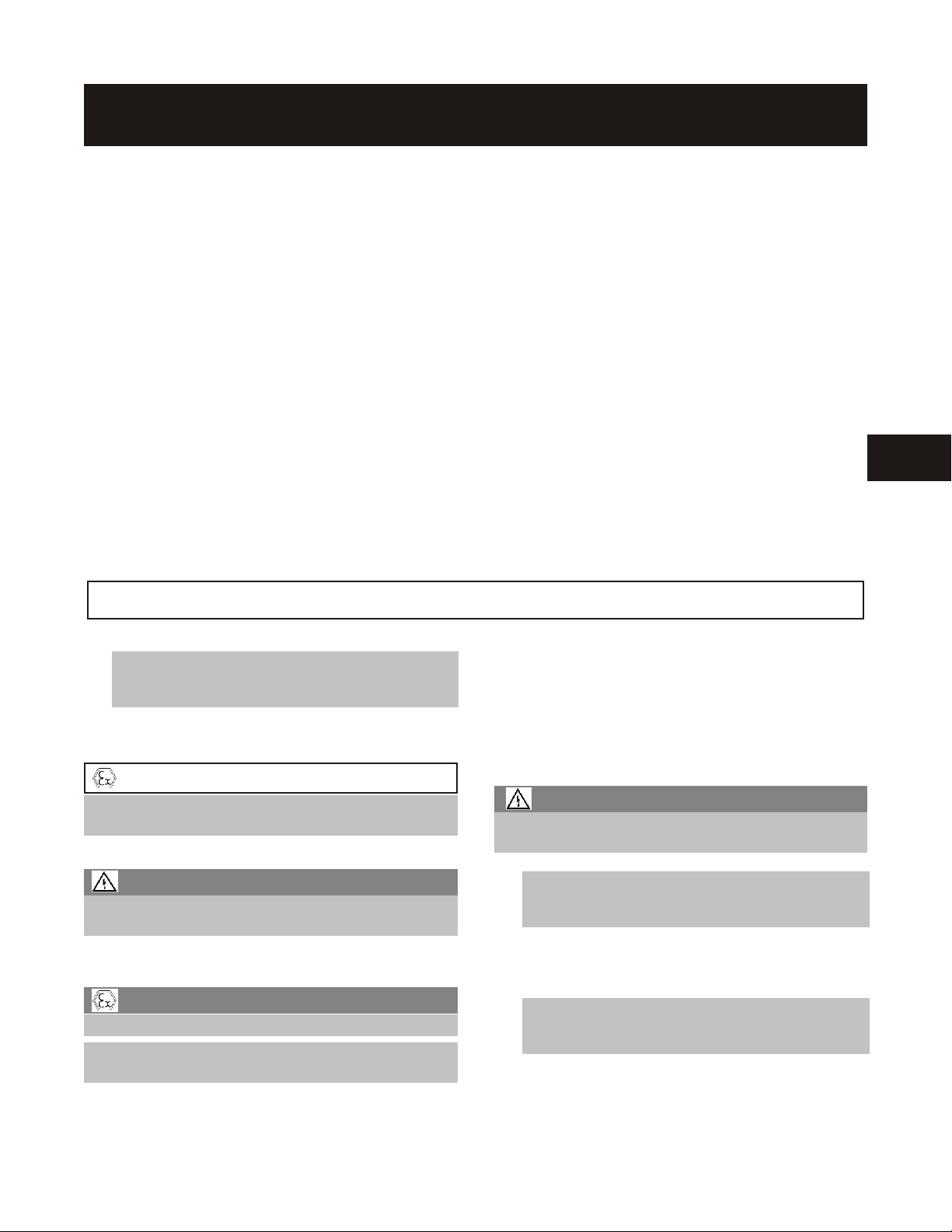
ATEX IDENTIFICATION
For a pumping unit (pump, seal, coupling, motor and
pump accessories) to be certified for use in an ATEX
classified environment, the proper ATEX identification
must be present. The ATEX tag will be secured to the
pump or the baseplate on which it is mounted. A
typical tag will look like this:
The CE and the Ex designate the ATEX compliance.
The code directly below these symbols reads as
follows:
II = Group 2
2 = Category 2
G/D = Gas and Dust present
= Temperature class, can be T1 to T6
T4
(see following table 1)
Ta ble 1
Max per mis si ble
Code
sur face tem per a ture,
T1 842 (450) 700 (372)
T2 572 (300) 530 (277)
T3 392 (200) 350 (177)
T4 275 (135) 235 (113)
T5 212 (100) Option not available
T6 185 (85) Option not available
The code classification marked on the equipment
should be in accordance with the specified area
where the equipment will be installed. If it is not,
please contact your ITT/Goulds representative before
proceeding.
°F (°C)
Max per mis si ble
liq uid tem per a ture,
°F (°C)
INTENDED USE
The ATEX conformance is only applicable when the
pump unit is operated within its intended use. All
instructions within this manual must be followed at all
times. Operating, installing or maintaining the pump
unit in any way that is not covered in this manual can
cause serious personal injury or damage to the
CONDITION MONITORING
For additional safety precautions, and where
!
noted in this manual, condition monitoring
devices should be used. This includes, but is
not limited to:
• Pressure gauges
• Flow meters
• Level indicators
• Motor load readings
• Temperature detectors
• Bearing monitors
• Leak detectors
• PumpSmart control system
equipment. This includes any modification to the
equipment or use of parts not provided by ITT/Goulds.
If there is any question regarding the intended use of
the equipment please contact an ITT/Goulds
representative before proceeding.
For assistance in selecting the proper instrumentation
and its use, please contact your ITT/Goulds
representative.
3700-10th IOM 12/04 9

10 3700-10th IOM 12/04

GENERAL INFORMATION
PUMP DE SCRIP TION.............................11
NAME PLATE IN FOR MA TION.........................12
RE CEIV ING THE PUMP ............................13
Stor age Re quire ments ...........................13
Han dling ..................................13
PUMP DESCRIPTION
2
The Model 3700 is a high pressure, high temperature
centrifugal pump that meets the requirements of
API Standard 610 10th Edition (ISO 13709).
The model is based on 6 power ends and 38 hydraulic
pump sizes.
Casing - The casing is a centerline mounted design.
The gasket is fully confined. ANSI Class 300 raised
face serrated flanges are standard; ANSI Class 300
flat face serrated and ring joint flanges are available.
Also available are ANSI class 600 flanges in the same
types.
Impeller - The impeller is fully enclosed and key
driven by the shaft. An impeller bolt with lockwasher
or impeller nut with locking set screw prevents axial
movement.
Seal Chamber Cover - The Model 3700 seal
chamber cover meets API 682 2nd Edition
dimensions for improved performance of mechanical
seals.
Power End - Ring oil lubricated bearings are
standard. The power end is sealed with labyrinth
seals. Pure and purge oil mist lubrication are options.
Some machining is required to convert from ring oil
lubrication to oil mist.
Shaft - The standard shaft is machined and ground to
comply with API 610 10th Edition (ISO 13709) criteria.
Bearings - The inboard (radial) bearing carries only
radial load; it is free to float axially in the frame. The
outboard (thrust) bearing is shouldered and locked to
the shaft and retained in the bearing frame to enable
it to carry radial and thrust loads. All fits are precision
machined to industry standards. The inboard bearing
is a single row deep groove ball bearing. The
outboard bearing is a duplex angular contact bearing,
which uses a pair of single row angular contact ball
bearings mounted back-to-back.
Baseplate - The fabricated steel baseplate is
designed to support the pump, driver and accessories
in accordance with API-610 10th Edition (ISO 13709)
requirements.
Direction of Rotation - Counterclockwise (left hand)
as viewed from the driver, looking at the pump shaft.
3700-10th IOM 12/04 11
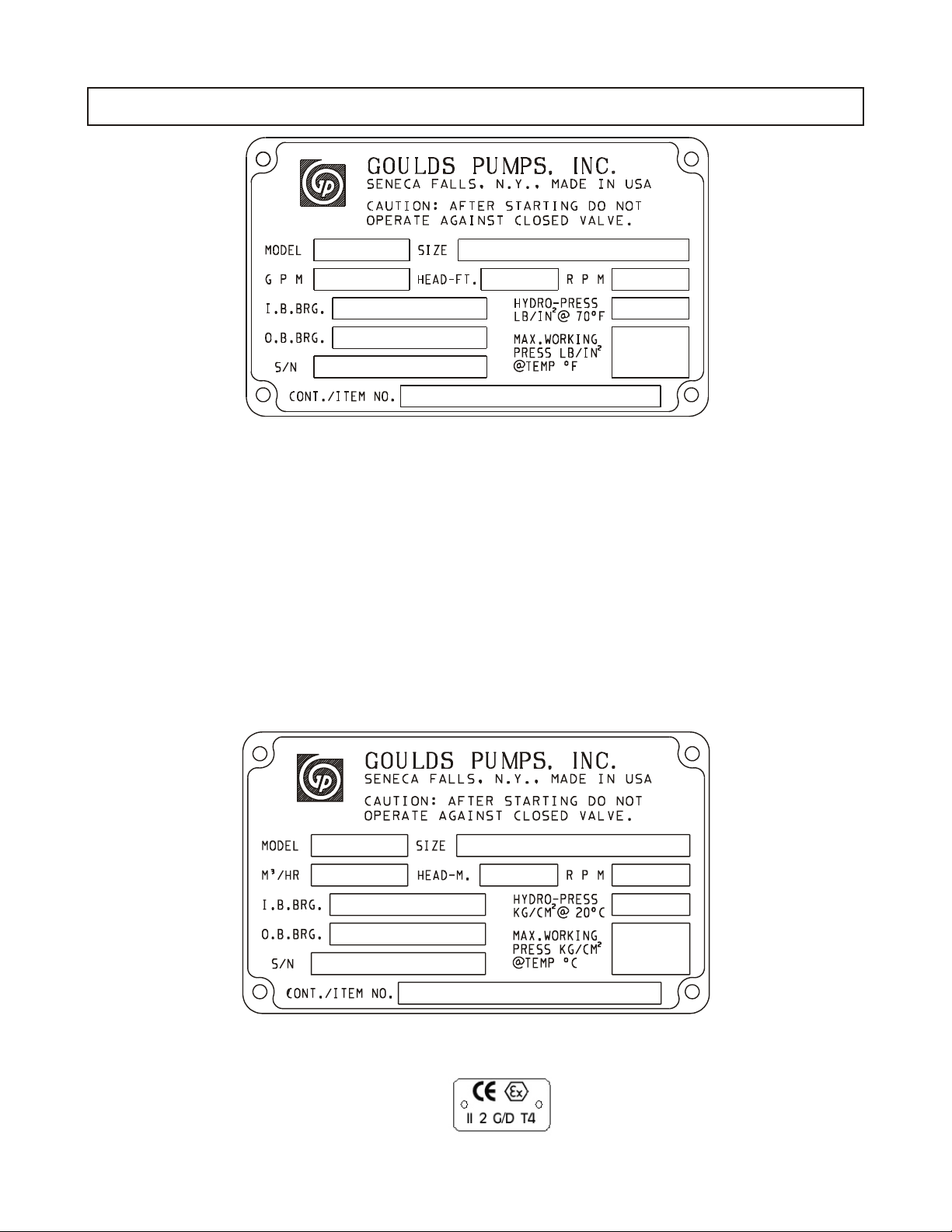
NAMEPLATE INFORMATION
Fig. 1
Every pump has a Goulds nameplate that provides
information about the pump. The nameplate is located
on the pump casing.
Special tags which provide additional information
(mechanical seal data, etc.) and special tagging
required by customers are located on the pump
casing or on the bearing frame.
The standard nameplate provides information about
the pump’s size, rating, bearings, serial number,
hydrostatic test pressure of pressure containment
parts, maximum allowable working pressure at
designated temperature and construction / customer’s
item number. Rating and hydrostatic test pressure
are expressed in English units. Note the format of
pump size: Discharge x Suction - Nominal Impeller
Diameter in inches, for example, 2x3-13 (Fig. 1).
The standard nameplate is also available in a version
which expresses the rating and hydrostatic test
pressure in metric units (Fig. 2).
When ordering spare parts you will need to identify
pump model, size, serial number, and the item
number of required parts. Pump information can be
taken from the Goulds nameplate. Item numbers can
be found in this manual.
Fig. 2
NOTE: If ap plicable, your pump unit may have the following ATEX tag affixed to the pump and/or base plate.
See the Safety sec tion for a de scription of the sym bols and codes.
12 3700-10th IOM 12/04

RECEIVING THE PUMP
Inspect the pump as soon as it is received. Carefully
check that everything is in good order. Make notes of
damaged or missing items on the receipt and freight
bill. File any claims with the transportation company
as soon as possible.
STORAGE REQUIREMENTS
Short Term (Less than 6 months)
Goulds normal packaging procedure is designed to
protect pump during shipping. Upon receipt, store in a
covered and dry location.
Long Term (More than 6 months)
Preservative treatment of bearings and machined
surfaces will be required. Rotate shaft several times
every 3 months. Refer to driver and coupling
manufacturers for their long term storage procedures.
Store in a covered and dry location.
2
NOTE: Long term storage treatment may be
purchased with initial pump order.
HANDLING
! WARN ING
s
Pump and components are heavy. Failure to
properly lift and support equipment could result
in serious physical injury, or damage to pumps.
Use care when moving pumps. Lifting equipment
must be able to adequately support the entire
assembly. Hoist bare pump using suitable slings
under the outboard end of the bearing frame and under
the suction flange (Fig. 3).
Fig. 4
Fig. 5
Fig. 3
Baseplate mounted units with or without drivers are
moved with slings through the baseplate’s lifting lugs
(Fig. 4 & 5).
3700-10th IOM 12/04 13

14 3700-10th IOM 12/04

INSTALLATION
GEN ERAL ...................................15
SITE/FOUN DA TION..............................15
BASE PLATE IN STAL LA TION PRO CE DURE.................16
Base plate Prepa ra tion ...........................16
Foun da tion Prepa ra tion ..........................16
Set ting and Lev el ing Base plate.......................16
ALIGN MENT AND ALIGN MENT CRI TE RIA .................17
Gen eral Con sid era tions ..........................17
Align ment Cri te ria .............................17
ALIGN MENT TROU BLE SHOOT ING.....................18
BASE PLATE GROUT ING PRO CE DURE ...................18
Gen eral Pro ce dure .............................18
Align ment Check ..............................18
PIP ING.....................................19
Suc tion Pip ing ...............................19
Dis charge Pip ing..............................20
By pass Pip ing ...............................20
Aux il iary Pip ing...............................20
Fi nal Pip ing Check .............................20
3
NOTE: Equipment that will op erate in a po tentially ex plosive en vironment must be installed in
!
ac cor dance with the fol low ing in struc tions.
GENERAL
Procedures for installation described within this section
are general in nature. It is assumed that the installer
has a basic knowledge of acceptable methods. More
detailed procedures are described in various publi-
cations, including API Recommended Practice 686/
PIP (Process Industry Practices) REIE 686,
“Recommended Practices for Machinery Installation
and Installation Design.”
SITE/FOUNDATION
A pump should be located near the supply of liquid
and have adequate space for operation, maintenance,
and inspection. Be sure to allow for crane or hoist
service.
Baseplate mounted pumps are normally grouted on a
concrete foundation which has been poured on a
solid footing. The foundation must be able to absorb
any vibration and to form a permanent, rigid support
for the pumping unit.
3700-10th IOM 12/04 15

NOTE: All equipment being installed must be
!
properly grounded to prevent unexpected
static electric discharge.
The location and size of foundation bolts are shown
on the outline assembly drawing provided with the
pump data package.
Foundation bolts commonly used are sleeve type
(Fig. 6) and J type. If using the sleeve type, the inside
diameter of the sleeve should be 2 1/2 - 3 times the bolt
diameter. A washer should be placed between the bolt
head and the sleeve. Both foundation bolt types permit
movement for final bolt adjustment.
BASEPLATE INSTALLATION PROCEDURE
Fig. 6
Industry standard procedures, such as API RP 686/
PIP REIE 686, and/or the following procedure should
be followed prior to grouting the baseplate. The
procedure assumes the installer has a basic
knowledge of baseplate and foundation design and
installation methods.
BASEPLATE PREPARATION
1. Inspect all surfaces of baseplate that will contact
grout for contamination (e.g. - rust, oil, grime, etc.).
2. Thoroughly clean all surfaces of the baseplate
that will contact grout with a cleaner that will not
leave any residue.
NOTE: It may be necessary to sandblast the
contact surfaces and coat with a primer compatible with the grout. If sandblasting is necessary,
remove all equipment prior to sandblasting.
3. Inspect all machined surfaces for burrs, rust, paint
or any other type of contamination. If necessary,
use a honing stone to remove burrs.
FOUNDATION PREPARATION
1. Chip top of foundation a minimum of 25 mm
(1.0 in.) to remove porous or low strength
concrete. If using a pneumatic hammer, assure
that it is not contaminating the surface with oil,
moisture, etc.
$
Do not use heavy tools such as jackhammers,
as they could damage the structural integrity of
the foundation.
2. Remove water and/or debris from foundation bolt
holes/sleeves. If the sleeve type bolts are being
used, fill the sleeves with nonbinding moldable
CAUTION
material and seal to prevent grout from entering.
3. Coat exposed portion of anchor bolts with a
non-bonding compound such as paste wax to
prevent grout from adhering to anchor bolts.
NOTE: Do not use oils or liquid wax.
4. If recommended by grout manufacturer, coat
foundation surface with a compatible primer.
SETTING AND LEVELING BASEPLATE
1. Lower baseplate carefully onto foundation bolts
(Fig. 7).
Fig. 7
2. Use leveling (jack) screws to raise bottom edge of
the baseplate 25 - 50 mm (1-2 in.) above
foundation to allow for adequate grouting. This
will provide even support for the baseplate once it
is grouted.
3. Level baseplate to within 0.20 mm/m (.002 in./ft.)
of length or width of the baseplate, respectively,
by adjusting leveling screws. Maximum total
variation from one end or side of the baseplate to
the other is 0.38 mm (.015 in.).
16 3700-10th IOM 12/04

Equipment mounting surfaces should be utilized
to establish level.
4. Coat portions of leveling screws that will contact
grout with a non-bonding compound such as
paste wax to facilitate their removal after grouting.
ALIGNMENT AND ALIGNMENT CRITERIA
NOTE: Do not use oils or liquid wax.
5. Thread nuts on foundation bolts and hand tighten.
NOTE: Alignment procedures must be
!
followed to prevent unintended contact of
rotating parts. Follow coupling
manufacturer's installation and operation
procedures.
GENERAL CONSIDERATIONS
! WARN ING
s
Before beginning any alignment procedure,
make sure driver power is locked out. Failure
to lock out driver power will result in serious
physical injury.
To remove coupling guard, refer to coupling guard
installation and disassembly instructions in Appendix I.
The times at which alignment is checked and adjusted
are:
Initial Alignment (Cold Alignment) is done prior to
operation when the pump and the driver are at
ambient temperatures.
Before Grouting Baseplate - To ensure
•
alignment can be obtained.
After Connecting Piping and Grouting
•
Baseplate - To ensure pipe strains haven’t
altered alignment.
Accurate alignment of the equipment must be
attained. Trouble-free operation can be accomplished
by achieving alignment within the levels specified in
the following section.
Three common alignment methods are utilized:
Reverse Dial Indicator method is most common.
•
Laser method is similar to reverse dial
•
indicator method, but uses a laser to obtain the
necessary measurements.
Dial Indicator (rim-and-face) method.
•
Follow alignment equipment manufacturers’
procedures when utilizing reverse dial indicator or
laser methods. A detailed procedure for alignment
using the dial indicator (rim-and-face) method is
included as Appendix II.
ALIGNMENT CRITERIA
Good alignment is attained when readings as specified in
this section have been achieved with pump and driver at
operating temperatures (final alignment).
Table 1 shows maximum allowable Total Indicator
Reading (T.I.R.) for parallel and angular misalignment.
3
Final Alignment (Hot Alignment) is done after
operation when the pump and driver are at operating
temperatures.
After First Run - To obtain correct alignment
•
when both pump and driver are at operating
temperature. Thereafter, alignment should be
checked periodically in accordance with plant
operating procedures.
NOTE: Alignment check must be made if
process temperature changes, piping changes
and/or pump service is performed.
Alignment is achieved by adding or removing shims
from under the driver and/or shifting driver horizontally
as needed.
NOTE: Proper alignment is the responsibility
of the installer and user of the unit.
3700-10th IOM 12/04 17
Par al lel and An gu lar Mis align ment
NOTE A: For electric motors, motor shaft initial
(cold) parallel vertical alignment setting should be
0.05 - 0.10 mm (.002-.004 in.) lower than pump
shaft.
NOTE B: For other drivers (turbines, engines, etc.),
follow driver manufacturers’ recommendations.
Maxi mum Al low able
Group
All
Ta ble 1
Maxi mum Al low able Mis align ment
Par al lel An gular
0.03 de grees
0.05 mm
(.002 in.)
[0.125 mm/cm
(.0005 in. /in.) of cou -
pling face
di ame ter]

ALIGNMENT TROUBLESHOOTING
Prob lem Prob able Cause Rem edy
Can not ob tain hori zon tal (Side- to- Side)
align ment, an gu lar or par al lel
Can not ob tain ver ti cal (Top- to- Bottom) align ment,
an gu lar or par al lel
BASEPLATE GROUTING PROCEDURE
Driver feet bolt bound.
Baseplate not lev eled
prop erly, proba bly twisted.
Baseplate not lev eled
prop erly, proba bly bowed.
Loosen pump hold down bolts and slide pump
and driver un til hori zontal align ment is achieved.
Determine which cor ner(s) of the base plate are
high or low and ad just lev eling screws at the
ap pro pri ate cor ner(s) and rea lign.
Determine if cen ter of base plate should be raised or
low ered and cor rect by ad just ing lev el ing screws
equally at the cen ter of the base plate.
GENERAL PROCEDURE
Use of non-shrink epoxy grout is recommended.
NOTE: Grout manufacturer’s instructions
should be consulted and followed.
The following are general procedures for grouting
baseplates. Additional information may be found in
API Standard 610, 8th Edition, Appendix L, API
RP 686, Chapter 5, and other industry standards.
Baseplate Installation Procedure should be followed
prior to grouting baseplate.
1. Build dam (form) around foundation to level of
bottom of baseplate (Fig. 8).
3. Strike along top of dam with trowel to give a neat
finished appearance.
4. Allow grout to set.
5. Fill remainder of baseplate with grout, removing
air as before (Fig. 9).
Fig. 9
6. Allow grout to set at least 48 hours. Leveling
screws should be removed when grout has
hardened.
7. Tighten foundation bolts.
Fig. 8
2. Pour grout through grout hole in baseplate, up to
level of dam. Remove air bubbles from grout as it
is poured by puddling or by pumping the grout into
place.
ALIGNMENT CHECK
Re-check alignment before continuing, using criteria
previously stated.
18 3700-10th IOM 12/04

PIPING
Guidelines for piping are given in the “Hydraulic
Institute Standards,” available from:
Hydraulic Institute
30200 Detroit Road
Cleveland, OH 44145-1967
and in API RP 686, and must be reviewed prior to
pump installation.
! WARN ING
s
Never draw piping into place by forcing at the
flanged connections of the pump. This may
impose dangerous strains on the unit and
cause misalignment between pump and driver.
Pipe strain will adversely affect the operation
of the pump resulting in physical injury and
damage to the equipment.
NOTE: Flange loads from the piping system,
!
including those from thermal expansion of
the piping, must not exceed the limits of the
pump. Casing deformation can result in
contact with rotating parts which can result
in excess heat generation, sparks and
premature failure.
1. Piping runs should be as short as possible to
minimize friction losses.
2. It is suggested that expansion loops be properly
designed and installed in suction and/or discharge
lines when handling liquids at elevated
temperatures, so thermal expansion of piping will
not draw pump out of alignment.
3. The piping should be arranged to allow pump
flushing prior to removal of the unit on services
handling hazardous liquids.
4. Carefully clean all pipe parts, valves and fittings,
and pump branches prior to assembly.
5. All piping must be supported independently of,
and line up naturally with, the pump flanges.
Table 2 shows piping flange alignment criteria.
Ta ble 2
Piping Flange Alignment
Type Cri te ria
Ax ial
Par al lel
Con cen tric Flange bolts should eas ily in stall by hand.
In no case should loads on the pump flanges
Flange gas ket thick ness ± 0.8 mm (.03 in.).
0.001 mm/mm (.001 in./in.) of flange di ameter
to a maxi mum of 0.8 mm (.03 in.).
exceed the limits stated in API Standard 610,
10th Edition (ISO 13709).
6. Piping must not be connected to the pump until
the grout has thoroughly hardened and the
foundation bolts, as well as driver and pump holddown bolts, have been tightened.
SUCTION PIPING
$
NPSHA must always exceed NPSHRas shown
on Goulds performance curves received with
order. (Reference Hydraulic Institute for NPSH
and pipe friction values needed to evaluate
suction piping).
Properly designed and installed suction piping is a
necessity for trouble-free pump operation. Suction piping
should be flushed BEFORE connection to the pump.
1. Use of elbows close to the pump suction flange
should be avoided. There should be a minimum
of two (2) pipe diameters of straight pipe [five (5)
pipe diameters is preferred] between the elbow
and suction inlet. Where used, elbows should be
long radius.
2. Use suction pipe one (1) or two (2) sizes larger
than the pump suction, with a reducer at the
suction flange. Suction piping should never be of
smaller diameter than the pump suction.
3. Reducers, if used, should be eccentric and
located at the pump suction flange with sloping
side down.
! !! CAUTION
$
Pump must never be throttled on suction side.
4. A suction screen should be installed prior to initial
start-up and when suction system has been
opened for work. The screen should be of the
cone type with a net area equal to at least three
(3) times the cross sectional area of the suction
pipe. The mesh of the screen should be sized to
prevent particles larger than 1.6 mm (1/16 in.)
from entering the pump and should be installed in
a spool piece to allow removal for cleaning. The
screen should remain in the system until periodic
inspection shows system is clean.
5. Separate suction lines are recommended when
more than one pump is operating from the same
source of supply.
ACAU TION
3
3700-10th IOM 12/04 19

Suction Lift Conditions
1. Suction pipe must be free from air pockets.
2. Suction piping must slope upwards to pump.
3. All joints must be air tight.
4. A means of priming the pump must be provided.
bypass line to preclude bypassing excessive flows.
Consult nearest sales office or factory for assistance
in sizing orifice.
An automatic recirculation control valve and/or
solenoid operated valve should be considered if a
constant bypass (i.e. orifice) is not possible.
Suction Head/Flooded Suction Conditions
1. An isolation valve should be installed in the
suction line at least two (2) pipe diameters from
the pump suction to permit closing of the line for
pump inspection and maintenance.
2. Keep suction pipe free from air pockets.
3. Piping should be level or slope gradually
downward from the source of supply.
4. No portion of the piping should extend below
pump suction flange.
5. The size of entrance from supply should be one
(1) or two (2) sizes larger than the suction pipe.
6. The suction pipe must be adequately submerged
below the liquid surface to prevent vortices and air
entrainment at the supply.
DISCHARGE PIPING
Properly designed and installed discharge piping is a
necessity for trouble-free pump operation. Discharge
piping should be flushed BEFORE connection to
the pump.
1. Isolation and check valves should be installed in
discharge line. Locate the check valve between
isolation valve and pump; this will permit
inspection of the check valve. The isolation valve
is required for priming, regulation of flow, and for
inspection and maintenance of pump. The check
valve prevents pump or seal damage due to
reverse flow through the pump when the driver is
turned off.
AUXILIARY PIPING
NOTE: The mechanical seal must have an
!
appropriate seal flush system. Failure to do
so will result in excess heat generation and
seal failure.
NOTE: Cooling systems such as those for
!
bearing lubrication, mechanical seal
systems, etc, where provided, must be
operating properly to prevent excess heat
generation, sparks and premature failure.
NOTE: Sealing systems that are not self
!
purging or self venting, such as plan 23,
require manual venting prior to operation.
Failure to do so will result in excess heat
generation and seal failure.
Auxiliary piping may be required for bearing cooling,
seal chamber cover cooling, mechanical seal flush or
other special features supplied with the pump.
Consult pump data sheet for specific auxiliary piping
recommendations.
If bearing cooling and/or seal chamber cover cooling is
required, follow guidelines listed below.
1. Flows of 4 l/min. (1 GPM) will generally satisfy
cooling requirements for each component. If both
bearing and seal chamber cover cooling are
provided, a minimum flow of 8 l/min. (2 GPM) will
be necessary.
2. Cooling water pressure should not exceed
7.0 kg/cm
2
(100 psig).
2. Increasers, if used, should be placed between
pump and check valves.
3. Cushioning devices should be used to protect the
pump from surges and water hammer if
quick-closing valves are installed in system.
BYPASS PIPING
Systems that require operation at reduced flows for
prolonged periods should be provided with a bypass
line connected from the discharge side (before any
valves) to the source of suction.
A minimum flow orifice can be sized and installed in
FINAL PIPING CHECK
After connecting the piping to pump:
Rotate shaft by hand to ensure it rotates
!
smoothly and there is no rubbing which
could lead to excess heat generation and or
sparks.
Check alignment, per alignment criteria
!
outlined previously, to determine if pipe
strain has affected alignment. If pipe strain
exists, correct piping.
20 3700-10th IOM 12/04
OPERATION
PREPA RA TION FOR START- UP.......................21
Check ing Ro ta tion .............................21
Coupling Pump and Driver .........................21
Lu bri cat ing Bear ings ............................22
Shaft Seal ing................................22
Prim ing Pump ...............................22
Start- up Pre cau tions ............................24
START ING PUMP ...............................24
OP ERA TION..................................25
Gen eral Con sid era tions ..........................25
Op era tional Checks ............................25
Op er at ing at Re duced Ca pac ity ......................25
Op er at ing Un der Freez ing Con di tions ...................25
SHUT DOWN ..................................26
FI NAL ALIGN MENT ..............................26
DOW EL ING PUMP CAS ING .........................26
4
PREPARATION FOR START-UP
NOTE: When installing in a potentially
!
explosive environment, ensure that the motor
is properly certified.
CHECKING ROTATION
$
Serious damage may result if pump is run in the
wrong rotation.
1. Lock out power to driver.
! WARN ING
s
Lock out driver power to prevent accidental
start-up and physical injury.
2. Make sure coupling hubs are securely fastened
to shafts.
! WARN ING
s
Do NOT jog a coupled pump.
NOTE: Pump is shipped with coupling spacer
removed.
3. Unlock driver power.
CAUTION
4. Make sure everyone is clear. Jog driver just long
enough to determine direction of rotation. Rotation
must correspond to arrow on bearing frame.
5. Lock out power to driver.
COUPLING PUMP AND DRIVER
! WARN ING
s
Lock out driver power to prevent accidental
rotation and physical injury.
NOTE: The coupling used in an ATEX
!
classified environment must be properly
certified.
1. Install and lubricate coupling per manufacturer’s
instructions.
NOTE: The coupling guard used in an ATEX
!
classified environment must be constructed
from a non-sparking material.
2. Install coupling guard. Refer to coupling guard
installation instructions in Appendix I.
3700-10th IOM 12/04 21

! WARN ING
s
Never operate a pump without coupling guard
properly installed. Refer to Appendix I for
coupling guard installation instructions.
Personal injury will occur if pump is run
without coupling guard.
LUBRICATING BEARINGS
NOTE: Bearings must be lubricated properly
!
in order to prevent excess heat generation,
sparks and premature failure.
Ring Oil Lubrication
Ring oil lubricated ball bearings are standard on
Model 3700 8th Edition units.
$
The bearings are not lubricated at the factory.
Assure that oil rings are properly seated in grooves in
shaft, as described in Disassembly & Reassembly
section.
See Preventive Maintenance section for lubrication
recommendations.
Pure or Purge Oil Mist Lubrication
Pure or purge oil mist are optional features for the
Model 3700 8th Edition. Follow oil mist generator
manufacturer’s instructions. The inlet and outlet
connections are located on the top and bottom,
respectively, of the bearing frame.
CAUTION
Connection of Sealing Liquid
NOTE: The mechanical seal must have an
!
appropriate seal flush system. Failure to do
so will result in excess heat generation and
seal failure.
NOTE: Cooling systems such as those for
!
bearing lubrication, mechanical seal
systems, etc, where provided, must be
operating properly to prevent excess heat
generation, sparks and premature failure.
NOTE: Sealing systems that are not self
!
purging or self venting, such as plan 23,
require manual venting prior to operation.
Failure to do so will result in excess heat
generation and seal failure.
For satisfactory operation, there must be a liquid film
between seal faces to lubricate them. Refer to seal
manufacturer’s drawing for location of taps. Some
methods which may be used to flush/cool the seal
are:
Product Flushing - In this arrangement, the
•
pumpage is piped from the casing (and cooled in
an external heat exchanger when required) then
injected into seal chamber.
External Flush - A clean, cool compatible liquid is
•
injected from an outside source directly into seal
chamber. Flushing liquid must be at a pressure
0.35-1.05 kg/cm
pressure. Injection rate should be 2-8 l/min. (
2
(5-15 psi) greater than seal chamber
1
-2 GPM).
2
See Preventive Maintenance section for lubrication
recommendations and connection locations.
! WARN ING
s
Operation of the unit without proper lubrication
will cause bearing failure and pump seizure.
SHAFT SEALING WITH MECHANICAL SEAL
NOTE: The mechanical seeal used in an
!
ATEX classified environment must be
properly certified.
Pumps may be shipped with or without mechanical
seal installed. Cartridge type mechanical seals are
commonly used for this model. Cartridge seals are
preset at the seal manufacturer’s facility and require
no field settings. Cartridge seals installed by the user
require disengagement of the holding clips prior to
operation, allowing the seal to slide into place. If the
seal has been installed in the pump by Goulds, these
clips have already been disengaged. For other types
of mechanical seals, refer to the seal manufacturer’s
instructions for installation and setting.
Other methods may be used which make use of
•
multiple gland connections and/or seal chamber
connections. Refer to documentation supplied with
the pump, mechanical seal reference drawing, and
piping diagrams.
PRIMING PUMP
NOTE: Pumps must be fully primed at all times
!
during operation.
Never start the pump until it has been properly
primed. Several different methods of priming can be
used, depending upon type of installation and service
involved.
Suction Supply Above Pump
1. Slowly open the suction valve (Fig. 10).
2. Open air vents on the suction and discharge piping,
casing, seal chamber, and seal piping, if provided,
until all air is vented and only liquid flows out.
3. Close the vents.
22 3700-10th IOM 12/04

Fig. 10
Suction Supply Below Pump
A foot valve and outside source of liquid may be used
to prime the pump. Outside source of liquid can come
from a priming pump, pressurized discharge line, or
other supply (Fig. 11 and 12).
Fig. 12
1. Close discharge valve and open air vents in
suction and discharge piping, casing, seal
chamber and seal piping, if provided.
2. Open valve in outside supply line until all air is
vented and only liquid flows out.
! WARN ING
s
When handling hazardous and/or toxic fluids,
proper personal protective equipment is
required. If pump is being drained, precautions
must be taken to prevent physical injury.
Pumpage must be handled and disposed of in
conformance with applicable regulations.
3. Close the vents and then the outside supply line.
Other Methods of Priming Pump
Priming by ejector.
•
Priming by automatic priming pump.
•
Fig. 11
3700-10th IOM 12/04 23

$
CAUTION
3. Variable speed drivers should be brought to rated
speed as quickly as possible.
START-UP PRE CAU TIONS
!
NOTE: Ensure that pump and systems are
!
free of foreign objects before operating and
that objects cannot enter the pump during
operation. Foreign objects in the pumpage or
piping system can cause blockage of flow
which can result in excess heat generation,
sparks and premature failure.
NOTE: A build up of gases within the pump,
!
sealing system and or process piping system
may result in an explosive environment
within the pump or process piping system.
Ensure process piping system, pump and
sealing system are properly vented prior to
operation.
1. All equipment and personal safety related devices
and controls must be installed and operating properly.
2. To prevent premature pump failure at initial
start-up due to dirt or debris in the pipe system,
ensure the pump can be run continuously at full
speed and flow for 2 to 3 hours.
4. Variable speed drivers should not be adjusted or
checked for speed governor or overspeed trip
settings while coupled to the pump at initial
start-up. If settings have not been verified,
uncouple the unit and refer to driver
manufacturer’s instructions for assistance.
5. Running a new or rebuilt pump at slow speeds
may not provide enough flow to adequately flush
and cool the wear ring and seal chamber cover
bushing close running surfaces.
6. Pumpage temperatures in excess of 93° C (200° F)
will require warm-up of pump prior to operation.
Circulate a small amount of pumpage through the
pump until the casing temperature is within 56° C
(100° F) of the pumpage temperature and evenly
heated.
NOTE: Warm-up rate should not exceed 1.4° C
(2.5° F) per minute.
STARTING PUMP
1. Make sure suction valve and any recirculation or
cooling lines are open.
2. Fully close or partially open discharge valve as
dictated by system conditions.
3. Start driver.
!
$
Immediately observe pressure gauges. If
discharge pressure is not quickly attained,
stop driver, reprime and attempt to restart.
CAUTION
4. Slowly open discharge valve until the desired flow
is obtained.
!
$
Observe pump for vibration levels, bearing
temperature and excessive noise. If normal
levels are exceeded, shut down and resolve.
CAUTION
24 3700-10th IOM 12/04
OPERATION
GENERAL CONSIDERATIONS
$
Always vary capacity with regulating valve in the
discharge line. NEVER throttle flow from the
suction side.
Driver may overload if the pumpage specific
gravity (density) is greater than originally
assumed, or the rated flow rate is exceeded.
Always operate the pump at or near the rated
conditions to prevent damage resulting from
cavitation or recirculation.
CAUTION
OPERATIONAL CHECKS
$
The following are minimum operational checks
for the pump only. Consult driver and auxiliary
equipment manufacturers’ literature for
additional information.
1. On ring oil lubricated units, remove oil ring
viewing port plugs to verify that oil rings are
properly positioned in grooves on shaft, are
turning and are throwing oil. Replace plugs.
2. On pure or purge oil mist lubricated units,
remove viewing port plugs and assure oil mist is
flowing properly. Replace plugs.
CAUTION
7. Monitor all gauges to ensure pump is
running at or near rating and that suction screen
(when used) is not clogged.
OPERATING AT REDUCED CAPACITY
! WARN ING
s
Do NOT operate pump below minimum rated
flows or with discharge valve closed. These
conditions may create an explosive hazard due
to vaporization of pumpage and can quickly lead
to pump failure and physical injury.
$
Damage occurs from:
1. Increased vibration levels - Affects bearings,
seal chambers, and mechanical seals.
2. Increased radial load - Increases stress on shaft
and bearings.
3. Heat build up - vaporization causes rotating
parts to score or seize.
4. Cavitation - Increases damage to internal
surfaces of pump.
CAUTION
OPERATING UNDER FREEZING
CONDITIONS
Exposure to freezing conditions while pump is idle
could cause liquid to freeze and damage the pump.
3. On ring oil and purge oil mist lubricated units,
check oiler to ensure oil level has remained
steady.
4. Check bearing temperatures using a
pyrometer or other accurate temperature
measuring device. Monitor bearing temperature
frequently during initial operation to determine
if a bearing problem exists as well as to
establish normal bearing operating
temperature.
5. On units equipped with auxiliary piping,
assure that proper flows have been established
and that equipment is operating properly.
6. Establish baseline vibration readings to
determine normal running conditions. If it is
determined that the unit is running rough,
consult factory.
3700-10th IOM 12/04 25
Liquid inside pump should be drained. Liquid inside
auxiliary piping, if supplied, should also be drained.

SHUTDOWN
required
1. Slowly close discharge valve.
2. Shut down and lock out driver to prevent
accidental rotation.
FINAL ALIGNMENT
Note: Alignment procedures must be
!
followed to prevent unintended contact of
rotating parts. Follow coupling
manufacturer's installation and operation
procedures.
1. Run the unit under actual operating conditions for a
sufficient length of time to bring the pump and driver
and associated systems to operating temperature.
2. Shut down and lock out driver as described
above.
s
! WARN ING
When handling hazardous and/or toxic fluids,
proper personal protective equipment is
required. If pump is being drained, precautions
must be taken to prevent physical injury.
Pumpage must be handled and disposed of in
conformance with applicable regulations.
3. Remove coupling guard. Refer to coupling guard
installation and disassembly instructions in
Appendix I.
4. Check alignment while unit is still hot per
alignment criteria in Section 3.
5. Reinstall coupling guard. Refer to coupling guard
installation and disassembly instructions in
Appendix I.
! WARN ING
s
Before beginning any alignment procedure,
make sure driver power is locked out. Failure
to lock out driver power will result in serious
physical injury.
DOWELING PUMP CASING
The pump casing may be doweled to the baseplate
pedestals, if desired, to positively maintain position.
Two (2) Number 7 taper pins are supplied for this
purpose.
NOTE: Doweling should only be done after
final alignment has been completed.
1. Drill two holes, one in each casing mounting pad,
at the locations provided, using a 21/64 in. or “Q”
size drill.
The holes should be drilled through both the
casing mounting pads and the baseplate
pedestal, when possible. This makes cleaning
the metal chips produced from the drilling and
reaming operations easier. Take care to clean all
burrs and metal chips from the holes.
$
If water cooled pedestals have been provided,
do NOT drill through the baseplate pedestal or
leakage of cooling water will occur.
2. Ream the holes with a Number 7 taper pin
reamer to the proper fit with the taper dowel pins.
Pins should insert to a depth that leaves only the
threaded portion exposed when fully seated.
3. Seat taper pins firmly in holes with hardwood
block or soft faced hammer.
$
Failure to remove the dowel pins prior to
casing removal may result in casing damage.
CAUTION
CAUTION
26 3700-10th IOM 12/04

PREVENTIVE MAINTENANCE
GEN ERAL COM MENTS............................27
MAIN TE NANCE SCHED ULE.........................27
Rou tine Main te nance ............................27
Rou tine In spec tions ............................27
3 Month Inspections ............................27
An nual In spec tions .............................27
MAIN TE NANCE OF BEAR INGS .......................28
Ring Oil Lu bricated Bear ings ........................28
Pure or Purge Oil Mist Lu bricated Bear ings (Op tional) ...........29
MAINTENANCE OF SHAFT SEALS .....................29
TROU BLE SHOOT ING.............................30
GENERAL COMMENTS
A routine maintenance program can extend the life of your pump. Well maintained
equipment will last longer and require fewer repairs. You should keep maintenance
records as this will help pinpoint potential causes of problems.
5
NOTE: The preventive maintenance section must be adhered to in order to keep the applicable
!
ATEX classification of the equipment. Failure to follow these procedures will void the ATEX
classification for the equipment.
MAINTENANCE SCHEDULE
ROUTINE MAINTENANCE
Bearing lubrication
•
Seal monitoring
•
Vibration analysis
•
Discharge pressure monitoring
•
Temperature monitoring
•
ROUTINE INSPECTIONS
Check for unusual noise, vibration and bearing
•
temperatures.
Inspect pump and piping for leaks.
•
Check seal chamber for leakage.
•
Oil should be changed at least every 3 months
•
(2000 hours) or more often if there are any adverse
atmospheric conditions or other conditions which might
contaminate or break down the oil. Oil should also be
changed if it is cloudy or contaminated.
Check shaft alignment and realign if required.
•
ANNUAL INSPECTIONS
Check pump capacity, pressure and power. If pump
•
performance does not satisfy your process requirements, and process requirements have not changed,
pump should be disassembled, inspected, and worn
parts should be replaced. Otherwise, a system
inspection should be done.
3 MONTH INSPECTIONS
Check foundation and hold-down bolts for tightness.
•
If pump has been left idle, check mechanical seal.
•
Repair or replace if required.
3700-10th IOM 12/04 27
Inspection intervals should be shortened
!
appropriately if the pumpage is abrasive
and/or corrosive, or if the environment is
classified as potentially explosive.

MAINTENANCE OF BEARINGS
NOTE: Do not insulate bearing housings as
!
this can result in excess heat generation,
sparks and premature failure.
RING OIL LUBRICATED BEARINGS
Ring oil lubricated ball bearings are standard on
Model 3700 8th Edition pumps.
! WARN ING
s
Pumps are shipped without oil. Oil lubricated
bearings must be lubricated at the job site.
A high quality turbine oil with rust and oxidation inhibitors
should be used. For the majority of operational
conditions, bearing temperatures will run between 50° C
(120° F) and 82° C (180° F). In this range, an oil of ISO
viscosity grade 68 at 40° C (100° F) is recommended. If
bearing temperatures exceed 82° C (180° F), use oil of
ISO viscosity grade 100.
Bearing temperatures are generally about 11° C
(20° F) higher than bearing housing outer surface
temperature.
Some acceptable oils are:
Exxon Teresstic EP 68
Mobil Mobil DTE 26 300 SSU
@ 40° C (100° F)
Fig. 13
NOTE: Setting dimension of 0 may be
accomplished by removing and discarding the
oiler adjusting stem.
Oil reservoir in bearing frame should be filled by filling
oiler bottle with oil and placing it into the oiler housing.
Several fillings of the oiler bottle will be required. Do
not fill bearing frame oil reservoir through the vent or
through the oiler housing without using the bottle.
Oil capacities and oiler information for the various
bearing frames are shown in Table 3.
Sunoco Sunvis 968
Royal Purple SYNFILM ISO VG 68
Synthetic Lube
For extreme conditions, refer to the factory or a
lubrication expert.
Oil should be changed after 200 hours if bearings are
new. Thereafter, change oil every 2000 operating
hours or 3 months, whichever first occurs.
Ring oil lubricated pumps are supplied with an oiler
which maintains a constant oil level in the bearing
housing. The oiler must be adjusted to maintain the
oil at the level of the mark on the side of the frame,
which corresponds to the center of the bullseye sight
glass. This is accomplished by setting the oiler
adjusting stem. Refer to Fig. 13 for proper setting
dimensions.
Ta ble 3
Bearing Frame Oil Ca pacities
Frame Oil Ca pacity Trico
Group
SA 600 20
SX 1115 38
MA 950 32
LA, MX 1385 47
LX 2120 72
XLX 2625 89
Verify the correct oil level by comparing the oil level
as viewed in the bullseye sight glass with the oil level
line on the side of the bearing frame.
ml Ounces ml Ounces
Oiler No.
5 237 8
Oiler Ca pac ity
28 3700-10th IOM 12/04
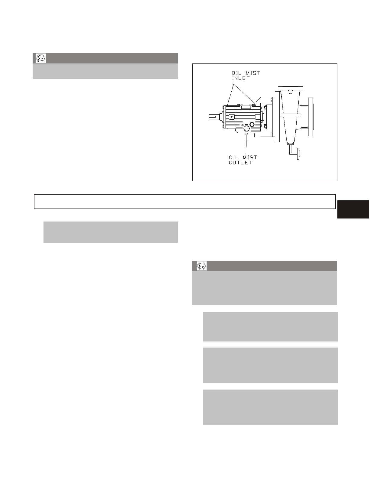
OPTIONAL PURE OR PURGE OIL MIST
LUBRICATED BEARINGS
! WARN ING
s
Pumps are shipped without oil. Oil mist lubricated
bearings must be lubricated at the job site.
The same oil requirements applicable to ring oil
lubricated bearings also apply to oil mist lubricated
bearings.
For purge oil mist lubricated bearings, bearing frame
should be filled to the proper level as described under
ring oil lubricated bearings.
Below are listed the steps necessary for oil mist
lubrication:
1. Follow oil mist system supplier’s instructions.
MAINTENANCE OF SHAFT SEALS
NOTE: The mechanical seal used in an ATEX
!
classified environment must be properly
certified.
When mechanical seals are furnished by Goulds, a
manufacturer’s reference drawing is supplied with the
data package. This drawing should be kept for future
use when performing maintenance and adjusting the
seal. The seal drawing will also specify required flush
liquid and attachment points. The seal and all flush
piping must be checked and installed as needed prior
to starting the pump.
2. Connect oil mist supply lines to inlet connections
(Fig. 14).
3. Connect drain/vent lines to outlet connections.
Fig. 14
The life of a mechanical seal depends on various
factors such as cleanliness of the liquid handled and
its lubricating properties. Due to the diversity of
operating conditions it is, however, not possible to
give definite indications as to its life.
! WARN ING
s
NEVER operate the pump without liquid supplied
to mechanical seal. Running a mechanical seal
dry, even for a few seconds, can cause seal
damage and must be avoided. Physical injury
can occur if mechanical seal fails.
5
NOTE: The mechanical seal must have an
!
appropriate seal flush system. Failure to do
so will result in excess heat generation and
seal failure.
NOTE: Cooling systems such as those for
!
bearing lubrication, mechanical seal
systems, etc, where provided, must be
operating properly to prevent excess heat
generation, sparks and premature failure.
NOTE Sealing systems that are not self
!
purging or self venting, such as plan 23,
require manual venting prior to operation.
Failure to do so will result in excess heat
generation and seal failure.
3700-10th IOM 12/04 29
 Loading...