

Page 1

Enidine / Conoflow
105 Commerce Way
Westminster, SC 29693
Tel: (864) 647-9521
Fax: (864) 647-7993
INSTRUCTION AND MAINTENANCE MANUAL
GFH45 PRESSURE REGULATOR
CAUTION: These instructions should be read
carefully prior to installation, use or
maintenance.
GENERAL PRODUCT OVERVIEW
Conoflow’s GFH45 Series Airpak®, Filter-Regulator is
used to provide clean, accurate air to instruments,
valves, positioners, transducers and other pneumatic
control devices. This unit’s design provides high flow
capability, durable materials of construction and bubble
tight shut-off.
The GFH45 Regulator has a maximum supply pressure
capability of 300 PSIG (2.07 MPa) with control output
settings of 0-25, 0-60 and 0-125 PSIG (0-172, 0-414 and
0-862 kPa). This brass filter regulator boasts a high flow
delivery rate and excellent droop characteristic.
This regulator is offered with ¼” NPT inlet and outlet
ports, two outlet gauge ports, and brass construction. A
handwheel or wrench knob adjustments are standard.
CAUTION: Maximum Supply Pressure is 300
PSIG (2.07 MPa)
WARNING: This product is not recommended
for use with flammable liquids or gasses.
WARNING
Conoflow’s products are designed and
manufactured using materials and
workmanship required to meet all applicable
standards. The use of these products
should be confined to services specified
and/or recommended in the Conoflow
catalogs, instructions, or by Conoflow
application engineers.
To avoid personal injury or equipment
damage resulting from misuse or
misapplication of a product, it is necessary
to select the proper materials of
construction and pressure-temperature
ratings which are consistent with
performance requirements.
MATERIALS OF CONSTRUCTION
Nozzle Assembly: Brass with Buna N Soft Seat
Range Spring: Zinc Plated Carbon Steel
Diaphragm Assembly: see CED Code
Bowl: Brass
Body: Brass
Bonnet: Brass
SPECIFICATIONS
Maximum Supply Pressure: 300 psig (2.07 MPa)
Outlet pressure ranges are determined by the last
character in the regulator model number.
“C” 25 psig (172 kPa)
“F” 60 psig (414 kPa)
“G” 125 psig (862 kPa)
Proof Pressure: 150% of maximum operating
Burst Pressure: 400% of maximum operating
Flow Capacity: 20 scfm (see flow chart)
Temperature Range: -20 °F to 165 °F
(-29 °C to 74 °C)
Sensitivity: 0.02 psi (0.14 kPa)
Connections: ¼” NPT Inlet and Outlet Ports,
Two-¼” NPT Gauge Ports
(90° from Outlet Port)
Weight: 3.4 lb (1.55 kg)
REGULATOR CLEANING
The GFH45 pressure regulator is cleaned to ITT
Conoflow specification ES8A 01 1 when option B is
selected in position 6 of the model number.
GFH45-IOM Rev. 0 12/18
Printed in USA
Page 2
INSTALLATION
CAUTION: The regulator must be installed with the
draincock downward to allow accumulated fluid to
drain out when the draincock is opened.
CAUTION: Moisture and particulates can be
discharged at high speed when draincock is
opened.
The GFH45 can be line mounted, panel mounted, or wall
mounted (reference G6018006 wall-mount bracket).
Teflon tape is the preferred thread sealant for the 1/4”
NPT connections.
Connect the supply to the port marked “IN”. The other
ports are outlet and factory plugged outlet gauge ports.
WARNING
port, regulator damage or unexpected flow through the
regulator could occur.
Prior to applying inlet pressure, double check the
connections and assure the wrench knob or hand wheel
is backed out sufficiently to unload the range spring in
the bonnet.
Carefully apply inlet pressure and check the supply
connection for leakage. Adjust the output pressure by
rotating the wrench knob or hand wheel clockwise and
check the outlet connection for leakage.
: If the supply line is connected to the outlet
WARNING: The handwheel or wrench knob can vibrate
loose and fall out if the jam nut is not tightened.
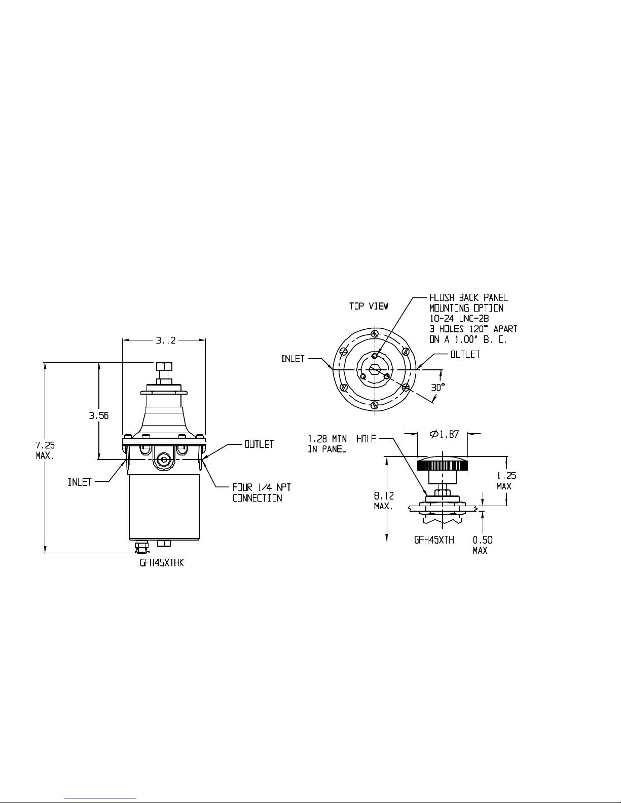
Figure 1 – Regulator dimensions with 1/4” NPT connections. For certified dimensional drawing, see A17-83.
Page 2 of 6 GFH45-IOM Rev. 0 12/18 Printed in USA
Page 3

CONTROL ENGINEERING DATA
Control Engineering Data is intended to provide a single
source from which one can determine, in detail, the full
scope of the product line. In addition to materials of
construction, diaphragm selection, filtering capabilities, it
also provides all necessary data for the mounting
options and control output setting ranges. Control
Engineering Data also provides a means of
communicating, by way of an 12 digit model number, a
full description of the product selection.
Characters 1-5: (Filter Regulator Model No.)
GFH45
Character 6: Filter Options
A = Cellulose (10 micron) – optional
B = Stainless Steel (40) micron-cleaned for
oxygen service) – optional
C = Stainless Steel (40 micron) – optional
X = Polypropylene (35 micron) – standard
Character 7: Bonnet Options
F = Front mount - optional
T = Threaded Bonnet - standard
Character 8: Adjustment Options
H = Handwheel - optional
K = Knob (Wrench Style) – standard
P = Preset (Factory Output Setting CAN be field
adjusted) – optional
C = Tamperproof (Factory Output Setting
Cannot be field adjusted)- optional
NOTE: 1. Customer must specify OUTPUT
SETTING, SUPPLY PRESSURE, and
FLOW.
Character 9: Diaphragm Selection
E = Buna “N” (w/Relief, No Bleed) – Standard
F = Viton on Nomex (No Bleed, No Relief)
J = Viton on Nomex (w/Relief, No Bleed)
M = Buna “N” (No Bleed, No Relief)
Character 10: Gauge Selections
X = No Gauge – standard
Character 11: Filter Bowl Option
1 = Standard (Bowl Size)
NOTE: Materials of construction and cleaning specifications
are the user’s responsibility.
Character 12: Control Ranges
C = 25 psig (172 kPa)
F = 60 psig (414 kPa)
G = 125 psig (862 kPa)
OPERATION IN SERVICE
Open upstream controls to provide the regulator supply
pressure. To increase the output set pressure, rotate the
knob or handwheel clockwise. To decrease the output set
pressure, rotate the knob or handwheel counterclockwise.
For non-relieving models (option “M” or “F” in character 9
position of the CED code), rotate the knob or handwheel
counterclockwise to reduce the output pressure when the
system is flowing.
When the system is being shut down, it is an established
safety practice to reduce the output pressure under flow then
shut off the supply pressure to the regulator. After all
pressure is relieved from the system, back out the control
knob until there is no spring resistance felt on the control
knob. This will assure that no output pressure will be
generated when the supply pressure to the regulator
resumes, the next time the system is used.
NOTE: The downstream pressure will change as the flow
changes. As the flow increases, the delivery pressure will
decrease.
NOTE: The outlet set pressure will change as the inlet
pressure changes. The output set pressure will increase as
the supply pressure decreases at an approximate rate of 0.3
psi per 25 psi decrease in the inlet pressure.
Page 3 of 6 GFH45-IOM Rev. 0 12/18 Printed in USA
Page 4

TROUBLESHOOTING GUIDE
Symptom: Outlet pressure continues to rise after flow
ceases.
Potential Cause: Valve seat leakage
Repair: Disassemble and clean regulator
components. Install new valve plug and filter element
(if applicable). Reassemble.
Symptom: External leakage
Potential Cause: Diaphragm to body joint seal
leakage.
Repair: Disassemble. Inspect regulator body where
diaphragm seals. Replace diaphragm assembly.
Potential Cause: Bowl to body joint leakage.
Repair: Disassemble. Inspect regulator body where
bowl o-ring contacts. Inspect bowl where o-ring
contacts. Replace o-ring.
Symptom: External leakage
Potential Cause: Draincock leakage.
Repair: Tighten draincock by turning handle
clockwise.
Symptom: Outlet pressure cannot be adjusted to
maximum control range.
Potential Causes:
1. Control knob positive stop adjustment.
2. Flow induced droop.
Repair:
1. Adjust positive stop of control knob.
2. A higher output range regulator may be required.
Symptom: Noisy operation.
Potential Causes: Turbulence in adjacent piping.
Repair: Insure that there are no elbows, line tees or
other turbulence creating piping directly upstream or
downstream of the pressure regulator.
Page 4 of 6 GFH45-IOM Rev. 0 12/18 Printed in USA
Page 5

FIGURE 2 – Cross Section of GFH45 Regulator
REPAIR AND MAINTENANCE
WARNING: To prevent equipment damage or injury, insure
that all system pressure is relieved and the supply valve for this
regulator is secured in the off position.
Cleanliness is critical to successful maintenance and repair of
this product. Perform all repair work in a clean environment, with
clean tools, and the correct materials and supplies.
Tools and Materials Required:
1. A vise, or other suitable fixture, to secure the regulator.
2. Phillips screwdriver
3. Socket wrenches
4. Torque Wrench
5. Lint free swabs or wipes to clean components
DISASSEMBLY
1. Secure the body of the regulator.
2. Turn control knob counterclockwise until the range
spring is unloaded.
3. Remove the six screws holding the bonnet to the body.
4. Remove the bonnet.
5. Remove the spring button and spring.
6. For 125 psi output units, remove the restricting plate
(note: the 0-60 psi model is shown in figure 2 and does
not have this restricting plate).
7. Remove the diaphragm assembly.
8. Unscrew the bolt and seal washer.
9. Remove the dripwell by pulling downward away from the
body.
10. Remove the filter.
11. To remove the plug spring and valve plug, unscrew the
retainer, then grip the plug spring and pull downward
away from the body. The plug and plug spring should
slide out of the body together.
ASSEMBLY
1. Replace worn or damaged components with new
components.
2. Clean and inspect components for reuse. Sealing
surfaces must be smooth and free of wear or scratches.
3. Install the valve plug and plug spring into the body.
Secure with the retainer. Torque retainer to 80 in-lb.
4. Replace the o-ring around the bowl with a new
lubricated o-ring.
5. If previously removed, install a new seal washer onto
the bolt. Install the filter plate, grommet and spring into
the dripwell, on the bolt.
6. Place a new filter in the body.
7. Install the dripwell by firmly pressing it over the o-ring.
The dripwell may be rotated to align the draincock to the
desired orientation. Secure the dripwell with the bolt,
tightened to 80 in-lb.
8. Assemble the diaphragm assembly, the restrictor plate
(for 125 psi models only), range spring, spring button
and bonnet. Secure bonnet with the six (6) bonnet
screws. Tighten snug (32 in-lb).
9. Lubricate (grease) and install the adjustment ( wrench
knob or handwheel), jam nut and any panel nuts and/or
mounting hardware.
Page 5 of 6 GFH45-IOM Rev. 0 12/18 Printed in USA
Page 6

FIGURE – 3 Exploded View of the GFH45
NOTES:
1. When ordering spare parts, specify complete Regulator Model Number., and Item Description. This will permit
positive identification and rapid handling of order.
2. Spare parts kit (standard configuration only)
a. G6385516 for the 0-25/60 psi (172/414 kPa) models
b. G6385517 for the 0-125 psi (862 kPa) model
3. For other model configurations or non-CED codeable models, consult factory for correct part number.
Page 6 of 6 GFH45-IOM Rev. 0 12/18 Printed in USA
 Loading...