

Page 1
BPHV
ITT
Commercial Water
Goulds Pumps
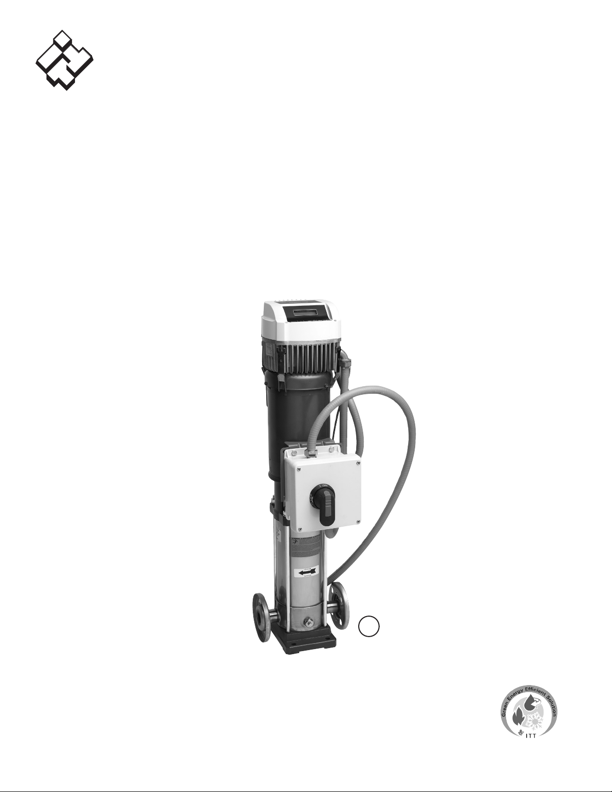
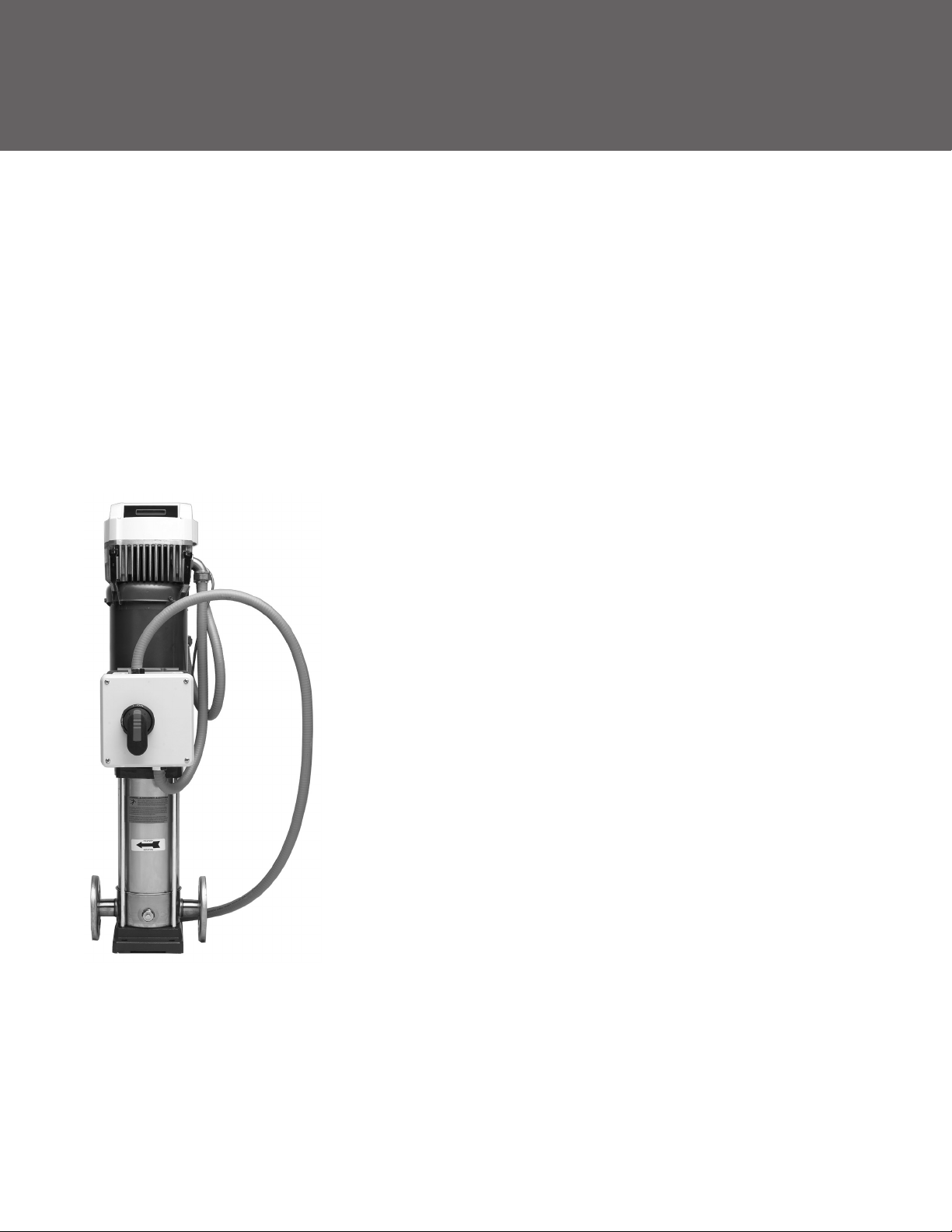
PHV – Packaged Hydrovar Series
Variable Speed Water Booster with
Vertical Multistage Pump and
Fused Disconnect
Engineered for life
U
L
®
C US
Listed
Page 2

Goulds Pumps
PHV - Packaged Hydrovar Series
CONTENTS
Selection Chart …………………………………………………………………………………………… 3
Main Components ………………………………………………………………………………………… 4
Part Numbering …………………………………………………………………………………………… 5
Markets and Applications ……………………………………………………………………………… 6-8
Hydrovar Specifications / Listings ……………………………………………………………………… 9-11
Multi-Pump Example ……………………………………………………………………………………… 12
Operation / Selecting ……………………………………………………………………………………… 13
Fused Disconnect ………………………………………………………………………………………… 15
Motor Data ………………………………………………………………………………………………… 17
Variable Speed Curves ……………………………………………………………………………… 19-36
Technical Data - Pump Hydraulics ………………………………………………………………… 37-40
Dimensions / Weights ……………………………………………………………………………… 41-46
Technical Data - References …………………………………………………………………………
48-49
2
Page 3
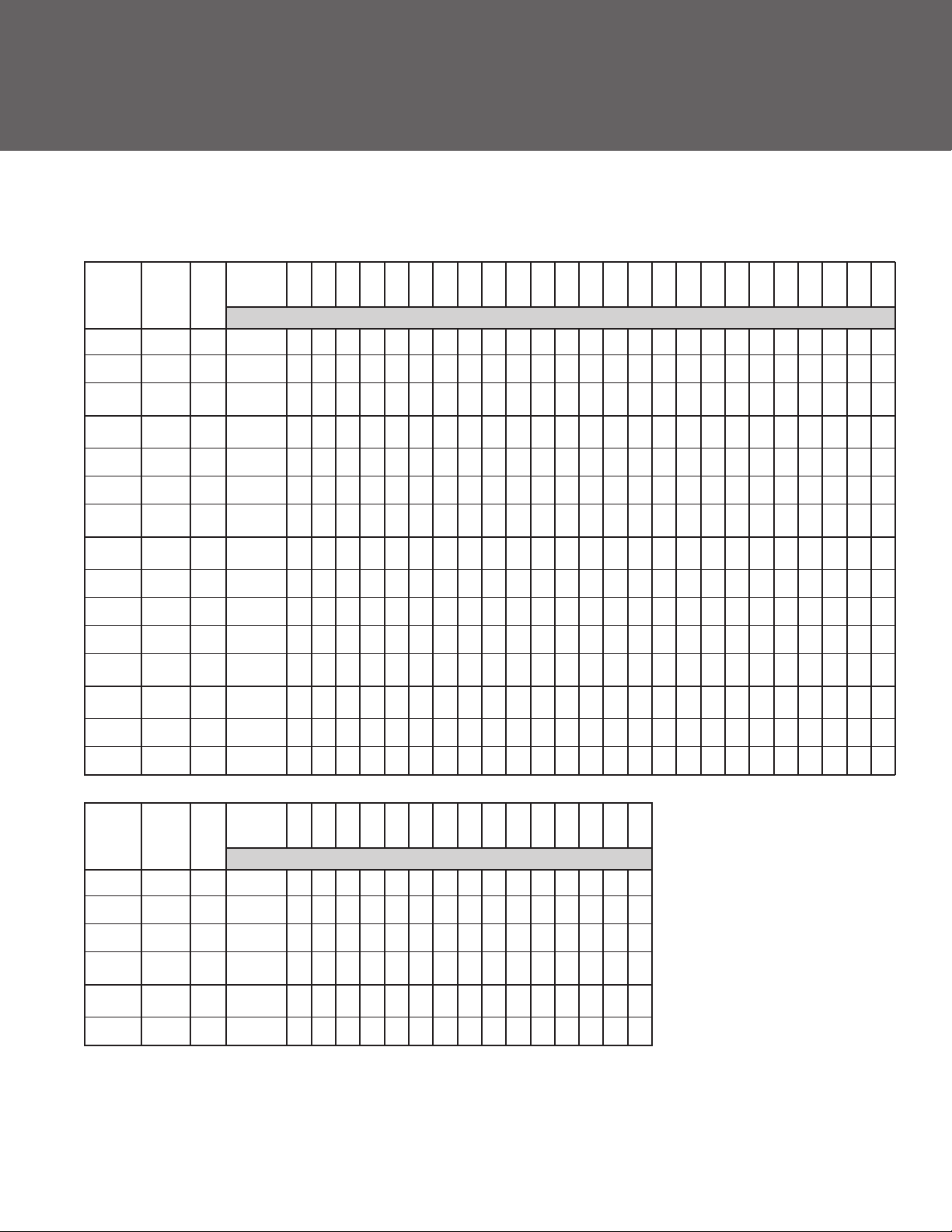
PHV SERIES SELECTION CHART (PACKAGED HYDROVAR)
HYDRAULIC PERFORMANCE RANGE AT 60 Hz
SSV FLOW
Pump Stage HP 0 GPM
Model
1SV 6 2
1SV 9 3
1SV 15 5
2SV 5 2
2SV 8 3
2SV 13 5
2SV 16 7.5
3SV 2 2
3SV 4 5
3SV 7 7.5
3SV 9 10
3SV 13 15
4SV 2 5
300 279 265 247 226 200 173 142
442 416 395 369 338 300 259 212
732 692 657 615 564 505 436 359
217 211 206 200 196 189 182 174 156 135 112 85
353 340 331 325 315 304 292 279 249 215 178 136
586 560 546 530 513 493 473 451 400 347 286 219
710 687 671 654 634 611 585 559 496 426 344 254
124 123 122 120 118 115 111 107 103 98 92 85 79 71 63
245 245 244 241 237 231 217 208 197 186 173 159 143 128
440 435 430 423 414 403 390 377 360 343 323 303 280 256 229
565 559 552 544 530 518 503 484 464 441 415 388 358 326 292
817 809 801 788 772 750 730 703 673 639 603 562 519 470 419
149 149 149 149 148 146 145 143 141 139 136 133 130 126 123 118 114 109 105 99
5 7.5 10 12.5 15 17.5 20 25 30 35 40 45 50 55 60 65 70 75 80 85 90 95 100 105 110
HEAD IN FEET
4SV 4 7.5
4SV 7 15
SSV FLOW
Pump Stage HP 0 GPM
Model
33SV 1/0 5
33SV 2/2 7.5
33SV 2/0 10
33SV 3/0 15
46SV 1/0 10
46SV 2/0 15
NOTE: Head in feet is boost pressure.
300 300 300 300 300 295 291 286 283 277 272 265 258 250 242 233 223 213 203 191
530 530 530 530 523 518 512 504 497 487 478 465 451 439 423 407 388 371 352 332
110 110 109 108 105 102 96 91 84 76 68
163 163 161 157 152 144 135 124 112 97 81
222 222 220 216 210 202 193 181 168 153 137
334 334 330 323 314 302 288 272 253 231 206
124 121 119 117 114 110 107 103 98 93 88 82 75 69 62 55
253 249 246 242 238 232 226 220 213 204 196 186 176 165 153 140
40 60 80 100 120 140 160 180 200 220 240 260 280 300 320
HEAD IN FEET
3
Page 4
Goulds Pumps
PHV - Packaged Hydrovar Series
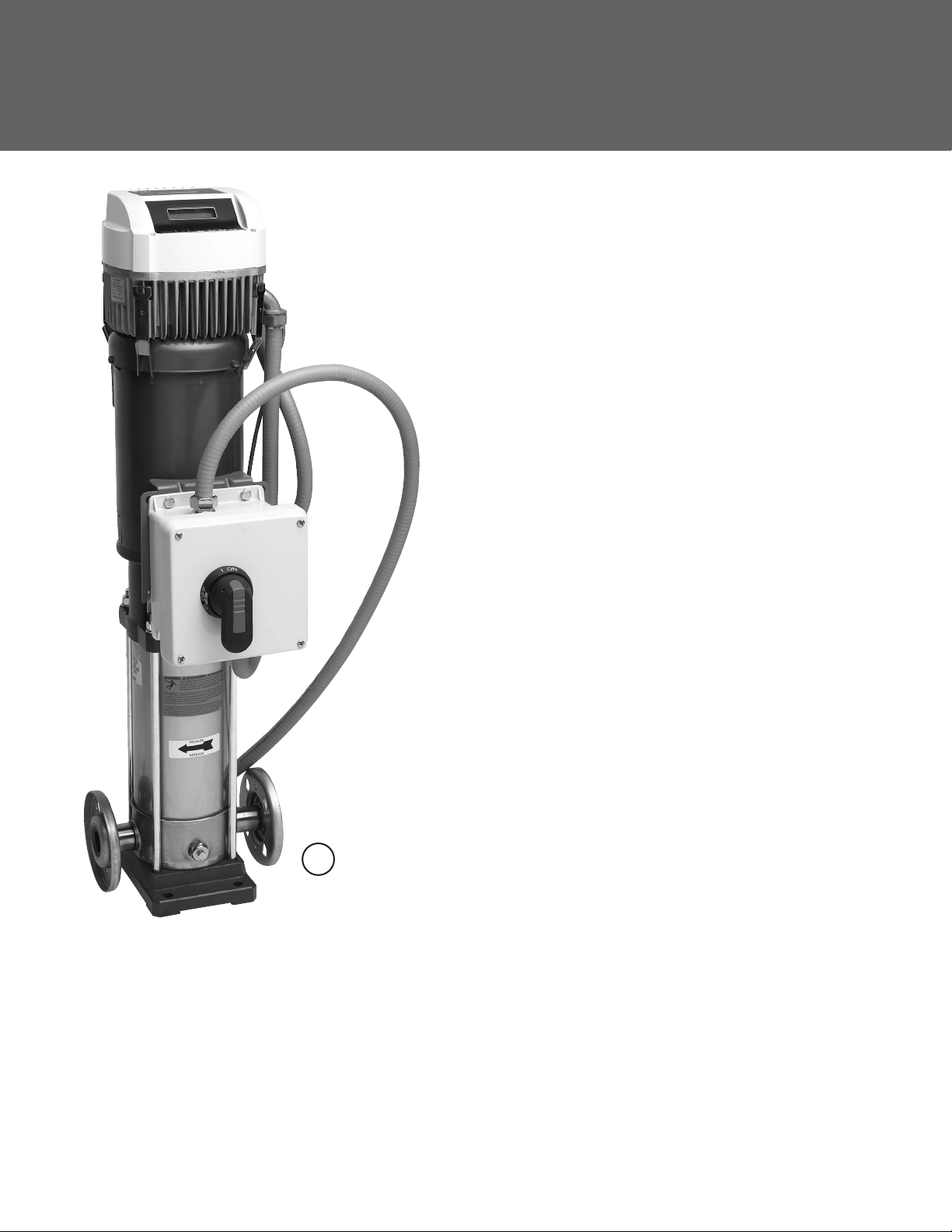
MAIN COMPONENTS
of PHV Series constant pressure variable
speed system
• One multistage vertical pump, Goulds Pumps SSV series.
• Hydrovar® pump mounted variable speed drive
• Pressure transducer for constant pressure control,
connected to the Hydrovar drive.
• NEMA 4X fused disconnect panel with corrosion resistant
durable plastic; external on/off switch with lockout/tagout. Panel
is bracket mounted directly to pump.
• Electrical panel for control and protection, with casing made
of plastic material, NEMA 4X, equipped with:
– fast acting fuses. The panel is mounted on the electric pump
using a bracket.
U
L
®
C US
Listed
“QCZJ7 Packaged Pumping System”
The pump package comes pre-assembled and tested,
complete with operating instructions and panel wiring diagram.
1) Vertical multi-stage stainless pump
2) TEFC standard NEMA 2-pole motor
3) NEMA 4X fused disconnect panel
4) ITT Hydrovar® variable speed controller
5) cUL flexible liquid tight conduit/wiring
6) Pressure transducer (sensor) with cable
7) Outdoor use
4
Page 5
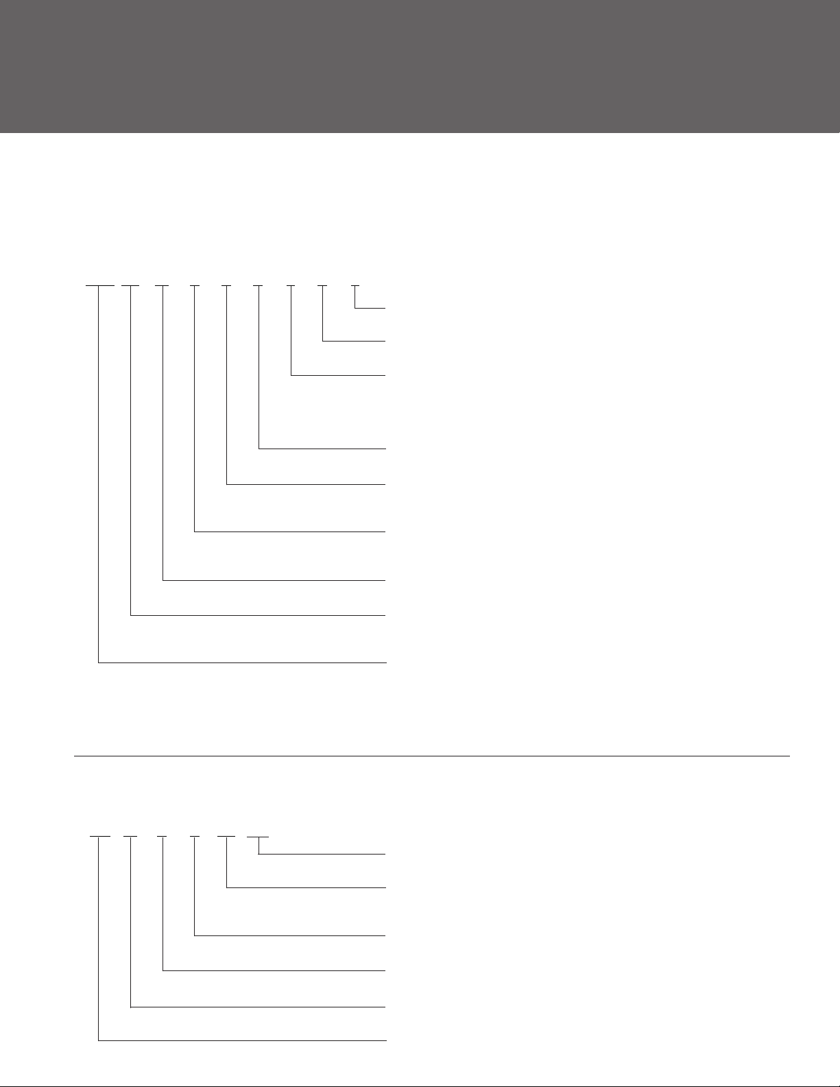
PART NUMBERING / IDENTIFICATION CODES — PHV SERIES
PACKAGED HYDROVAR VARIABLE SPEED SSV PRODUCT LINE NUMBERING SYSTEM
The various versions of the PHV line are identified by a product code number on the pump label. The number is
also the catalog number for the package. The meaning of each digit in the product code is shown below.
PHV 02 M 2 1 B E 0 P
Option List in order shown:
P = Premium Efficiency F = Harmonic Filter T = 500 PSI Transducer
Reduced Stages (33-46SV Only) (can be 0, 1 or 2)*:
0 = 0 reduced 1 = 1 reduced 2 = 2 reduced
Number of Stages:
A = 1 E = 5 J = 9 N = 13 S = 17 Z = 24
B = 2 F = 6 K = 10 P = 14 T = 18
C = 3 G = 7 L = 11 Q = 15 V = 20
D = 4 H = 8 M = 12 R = 16 X = 22
Flange Type:
A = NPT Oval B = ANSI D = 316SS ANSI
Pump Model:
1 = 1SV 2 = 2SV 3 = 3SV 4 = 4SV
5 = 33SV 6 = 46SV 7 = 66SV 8 = 92SV
Voltage:
2 = 230V
4 = 460V
Hydrovar Type:
M = Master Controller
HP Rating:
02 = 2 HP 03 = 3 HP 05 = 5 HP
07 = 7½ HP 10 = 10 HP 15 = 15 HP
PHV - Series (SSV & Hydrovar Package)
Notes:
1. Not all combinations are available. 4. Fuse box contains class J or equal fast acting fuses.
2. Standard motor is Baldor TEFC, 3 Phase, TC frame. 5. Tank, piping and valves sold separately.
3. Standard Hydrovar VSD is master - capable of multi-control. 6. Includes 300 PSI transducer.
* Notes: Indicates num-
ber of reduced diameter
impellers in the total staging.
(2 would indicate 2 reduced
diameter impellers.)
CAUTION: 500 PSI transducer measures accurately to
400 PSI. Pump, flanges and
other piping system components must also be rated
for the maximum system
pressure. See SSV technical
manual and other appropriate technical manuals to verify
all equipment is rated to
maximum system pressure.
HYDROVAR VARIABLE SPEED CONTROLLERS
Hydrovar variable speed drives are identified by the following code. The meaning of each digit in the product code
is shown below.
HV M 3 4 10
Filter (optional):
Standard = Blank Residential = B
HP Rating:
02 = 2 HP 03 = 3 HP 05 = 5 HP
07 = 7 HP 10 = 10 HP 15 = 15 HP
Voltage:
2 = 230V 4 = 460V
Phase:
1 = Single Phase 3 = Three Phase
Type:
M = Master S = Single B = Basic
HV - Series
5
Notes:
1. Not all combinations are
2. Includes drive, mounting
available.
hardware, 300 PSI transducer and conduit gland
and plugs.
Page 6
Goulds Pumps
PHV - Packaged Hydrovar Series
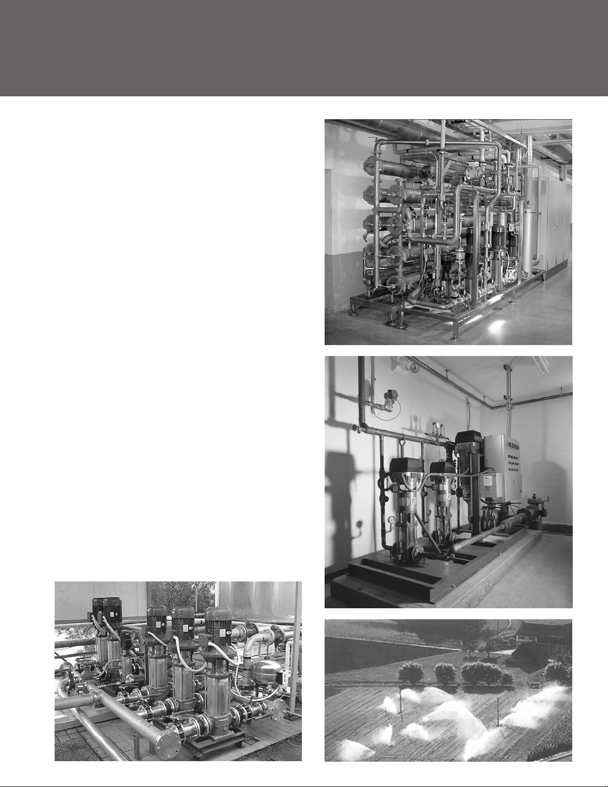
MARKETS AND APPLICATIONS
Booster
Sets
MARKETS SERVED
MUNICIPAL, COMMERCIAL, INDUSTRIAL
APPLICATIONS
• Water network supply in condominiums, offices, hotels,
shopping centers, factories, water treatment, process control.
• Water supply to agricultural water networks (e.g. irrigation).
• Variable flow / demand applications requiring constant pressure control.
PHV Series
SPECIFICATIONS
• Flow rate up to 320 GPM.
• Head up to 692’ TDH.
• Supply voltage:
1Ø, 230V ± 10% up to 3 HP.
3Ø, 400V ± 10% for 3 HP – 15 HP.
• Input Frequency: 50 or 60 Hz.
• External control voltage:
0-5 VDC; 0-10 VDC; 0-20 mA.
• Protection class
- panel: NEMA 4X.
- drive: NEMA 4 up to 15 HP.
- outdoor use.
• Maximum HP: 15 HP.
• Soft motor start.
• Vertical design pump:
- SV..T series (motor insulation
class, F, TEFC enclosure).
• Maximum operating pressure:
360 PSI for sets with SV..T electric
pumps.
• Maximum temperature of pumped
liquid: 180° F.
6
Page 7
MARKETS AND APPLICATIONS
(continued)
WATER SUPPLY AND PRESSURE BOOSTING
• Pressure boosting in buildings, hotels,
residential complexes
• Pressure booster stations, supply of water networks
• Booster packages
WATER TREATMENT
• Ultraltration systems
• Reverse osmosis systems
• Water softeners and de-mineralization
• Distillation systems
• Filtration
LIGHT INDUSTRY
• Washing and cleaning plants (washing and degreasing of
mechanical parts, car and truck wash tunnels, washing of
electronic industry circuits)
• Commercial washers
• Fireghting system pumps
IRRIGATION AND AGRICULTURE
• Greenhouses
• Humidiers
• Sprinkler irrigation
HEATING, VENTILATION AND AIR CONDITIONING (HVAC)
• Cooling towers and systems
• Temperature control systems
• Refrigerators
• Induction heating
• Heat exchangers
• Boilers
• Water recirculation and heating
7
Page 8

Goulds Pumps
PHV - Packaged Hydrovar Series
MARKETS AND APPLICATIONS
(continued)
MUNICIPAL, AGRICULTURAL, LIGHT INDUSTRY,
WATER TREATMENT, HEATING AND AIR CONDITIONING
APPLICATIONS
• Handling of water, free of suspended solids, in the municipal, industrial and agricultural markets
• Pressure boosting and water supply systems
• Fire ghting jockey pumps
• Irrigation systems
• Wash systems
• Water treatment plants: reverse osmosis
• Handling of moderately aggressive liquids, demineralized water, water and glycol, etc.
• Circulation of hot and cold water for heating, cooling and conditioning systems
• Boiler feed
SPECIFICATIONS
PUMP
The SSV pump is a non-self priming vertical multistage pump coupled to a standard motor.
The liquid end, located between the upper cover and the pump casing, is held in place by tie rods.
The pump casing is available with different configurations and connection types.
• Delivery: up to 600 GPM
• Head: up to 1200 feet
• Temperature of pumped liquid: -20ºF to 250ºF (-30ºC to 120ºC) standard version
• Maximum operating pressure – with oval anges: 230 PSI (15 bar)
– with round flanges or Victaulic: 360 PSI (25 bar)
– SV33, 46: 230, 360 or 575 PSI (16, 25 or 40 bar)*
– SV 66, 92: 230 or 360 PSI (16 or 25 bar)*
• Direction of rotation: clockwise looking at the pump from the top down (marked with an
arrow on the adapter and on the coupling).
MOTOR
• Standard NEMA TC Frame motors totally enclosed fan cooled.
• Efciency is 75.5% or higher, Class “F” insulation
• 3500 RPM nominal
• Standard voltage:
• Single phase version: 115-208/230 V, 60 Hz up to 3 HP or 208-230 V for 5 HP
• Three phase version, 2 pole: 208-230/460 V, 60 Hz up to 75 HP
* Based on pump staging
8
Page 9
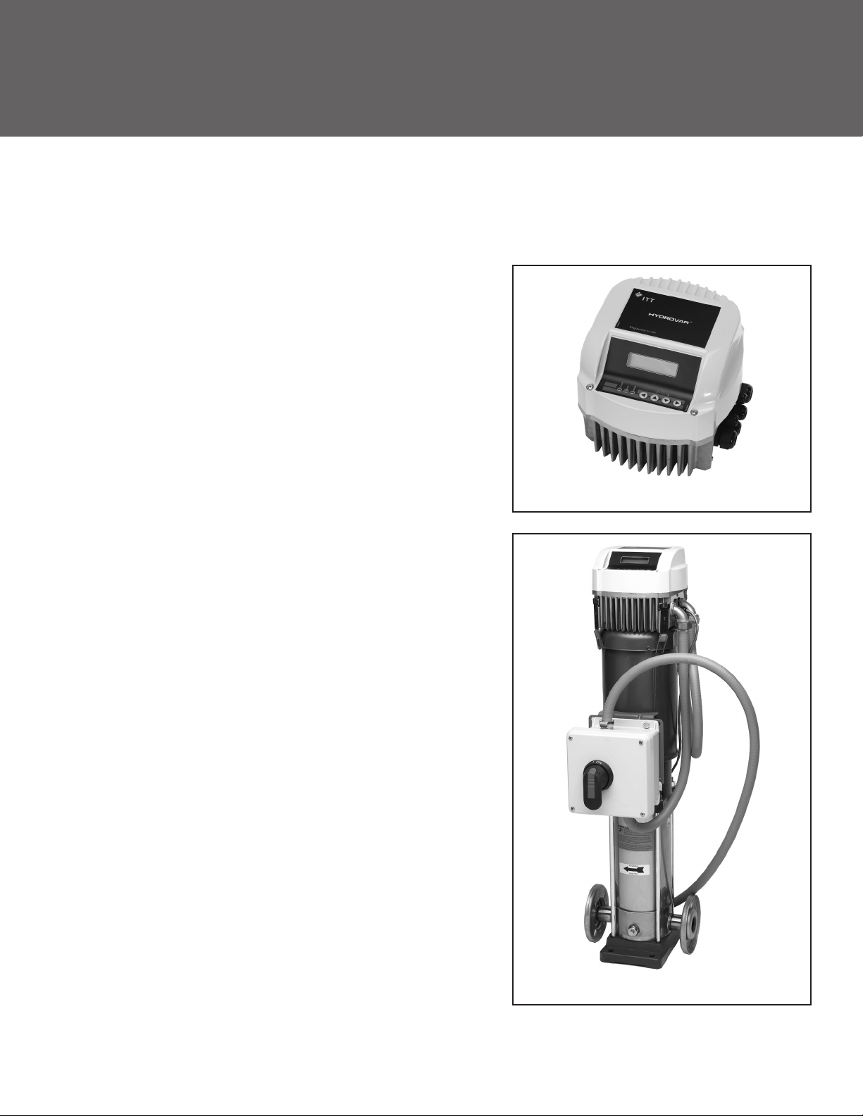
MAIN CHARACTERISTICS OF FREQUENCY CONVERTERS USED IN THE
PHV BOOSTER SETS
The PHV series booster sets use a Hydrovar® variable frequency drive, an automatic device that adjusts the speed of the
electric pump in order to maintain constant pressure in the system.
Converters with power up to 30 HP can be mounted directly on
to the motor. Models with over 30 HP power, are designed for wall
mounting only. The pressure is measured by a pressure transmitter
which uses a standard 4..20 mA current signal. The system pressure
value can be read on the converter’s display. A simple user interface
allows you to set the desired pressure value for optimal adjustment,
as well as to view the operating data, such as the hours of
operation and any alarms triggered. Included diagnostic menu to view
temperature, current and voltage values facilitates diagnostics and
failure analisys. Indicator lights signal power status, pump running and
malfunctions.
Modular Hydrovar, Bare Unit
A password is required to access sensitive settings that allow you
to program the Hydrovar in order to adapt it to any control
requirements, such as flow resistance compensation, external
control, periodic testing and so on. When more than one pump is
used, the converters exchange information with each other through an
RS485 serial line which can connect up to 8 Hydrovar devices plus
one external unit for remote control. The Pump-link and Pump-watcher
dedicated systems, connected to the Hydrovar®, enable remote
control through a traditional telephone line or mobile telephony. A
serial port available as standard up to 15 HP allows you to control the
Hydrovar® converters from a Modbus® field serial bus line.
The converter is equipped with two potential-free relays which can
be used for remote signalling of pump running and malfunction
status, plus a programmable voltage analogue output for signalling
the frequency or pressure. Standard version with two sensor inputs
for implementing of two actual values signals within one system (min/
max, difference) or for a second sensor for safety reasons. Specific
digital inputs are used for protection against water failure, motor
overtemperature, as well as for external enable signal and remote
control. The converter also incorporates a dry running protection
function via an adjustable minimum pressure threshold.
FCC Class A filter standard for Hydrovar three-phase power supply.
E.g. Industrial areas, technical areas of any building fed from a
dedicated transformer are examples of environment locations.
PHV Series Hydrovar with SSV Pump
FCC Class B filter standard for Hydrovar single-phase power supply.
E.g. Houses, apartments, commercial premises or offices in a residential building are examples of environment locations.
Further information is available in the Hydrovar manual.
9
Page 10

Goulds Pumps
PHV - Packaged Hydrovar Series
CHARACTERISTICS OF THE ELECTRIC PUMPS USED IN PHV SERIES
BOOSTER PACKAGE
1, 2, 3 AND 4 SSV VERTICAL MULTI-STAGE PUMPS
• Multistage centrifugal vertical electric pumps. All metal
parts in contact with pumped liquid are made of
304/316 stainless steel.
• A version: round anges, in-line discharge and suction
ports, AISI 304
• B version: ANSI anges, in-line discharge and suction
ports, AISI 316
SV33 AND 46 MULTI-STAGE PUMPS
• Vertical multistage centrifugal pump with impellers,
diffusers and outer sleeve made entirely of stainless steel,
and with pump casing and upper head made of cast
iron in the standard version.
• High hydraulic efciency for signicant energy savings.
• Innovative axial load compensation system on pumps
with higher head. This ensures reduced axial thrusts and
enables the use of standard motors that are easily found
on the market.
• Reduced axial thrusts enable the use of standard
motors that are easily found on the market.
• Standard Baldor, NEMA motors
• Easy maintenance. No special tools required for assembly
or disassembly.
• ANSI/NSF 61 certified by CSA for potable
drinking water.
• Standard NEMA Baldor® motors.
• Mechanical seal can easily be replaced without
disassembling the motor from the pump.
• Mechanical sturdiness and easy maintenance. No special
tools required for assembly or disassembly.
• ANSI/NSF 61 certified by CSA for potable
drinking water.
REFERENCE STANDARDS
• cUL Listed as pumping packaged unit, 42UC
• VFD (Hydrovar) UL recognized
• Baldor motor UL recognized
• Pumps meet ANSI/NSF 61 certification by CSA for potable drinking water
• Pumps meet ANSI/UL778 standards
• Control/disconnect meet UL508A standards
10
Page 11

HYDROVAR VERSIONS
INTRODUCTION
The HYDROVAR Concept consists mechanically of two main parts, the Power Unit and the
Control Card. In its basic configuration (consists only of the Power Unit) the HYDROVAR can be used as a
“Basic Inverter” without the need of the Control Card. In that form the HYDROVAR can be used as a sequence pump in
a multi pump system, with at least one master inverter.
By extending this “Basic Inverter” with the additional Control Card and LCD display, the HYDROVAR “Master Unit” is able
to work in different modes and can be extended by the implementation of different modules.
STANDARD OPTIONAL FEATURES VERSIONS
CASCADE SERIAL (MASTER + BASIC)
In this mode there are various possibilities to combine the different versions of the HYDROVAR.
In general, each of the pumps is equipped with a HYDROVAR unit. Each pump of the system (extended up to 8 pumps) is
equipped with a HYDROVAR unit (at least one “Master Inverter” and the others can be
“Basic Inverters” in order to ensure a proper control of the system) which are connected via the serial interface.
Minimum requirement: One “Master Inverter” and the others equipped with “Basic Inverters”.
The whole control is performed via the “Master Inverter” every time, but also an automatic change over of the lag pumps
to achieve even operating hours is possible.
Following versions are available:
• Power size 3 HP up to 15 HP motor mounted single phase and/or three phase power supply.
- PHV: one pump with wiring, fused disconnect, master Hydrovar drive, transducer, conduit.
11
Page 12
Goulds Pumps
PHV - Packaged Hydrovar Series
APPLICATION EXAMPLE – MULTI-PUMP “CASCADE”
MASTER
INVERTER
RS 485
CONNECTION
MASTER
INVERTER
MASTER
INVERTER
MASTER
INVERTER
With the “master” version of the Hyrdrovar, it is possible to connect up to 8 Hydrovar controller pumps together in
parallel. Complete lead/lag and auto alternation.
MASTER
INVERTER
RS 485
CONNECTION
BASIC
INVERTER
BASIC
INVERTER
BASIC
INVERTER
Reduction of overall cost for multi-pump system is possible using one “master” controller and several “basic” controllers. The Hydrovar “master” will still control lead/lag, alternation.
12
Page 13
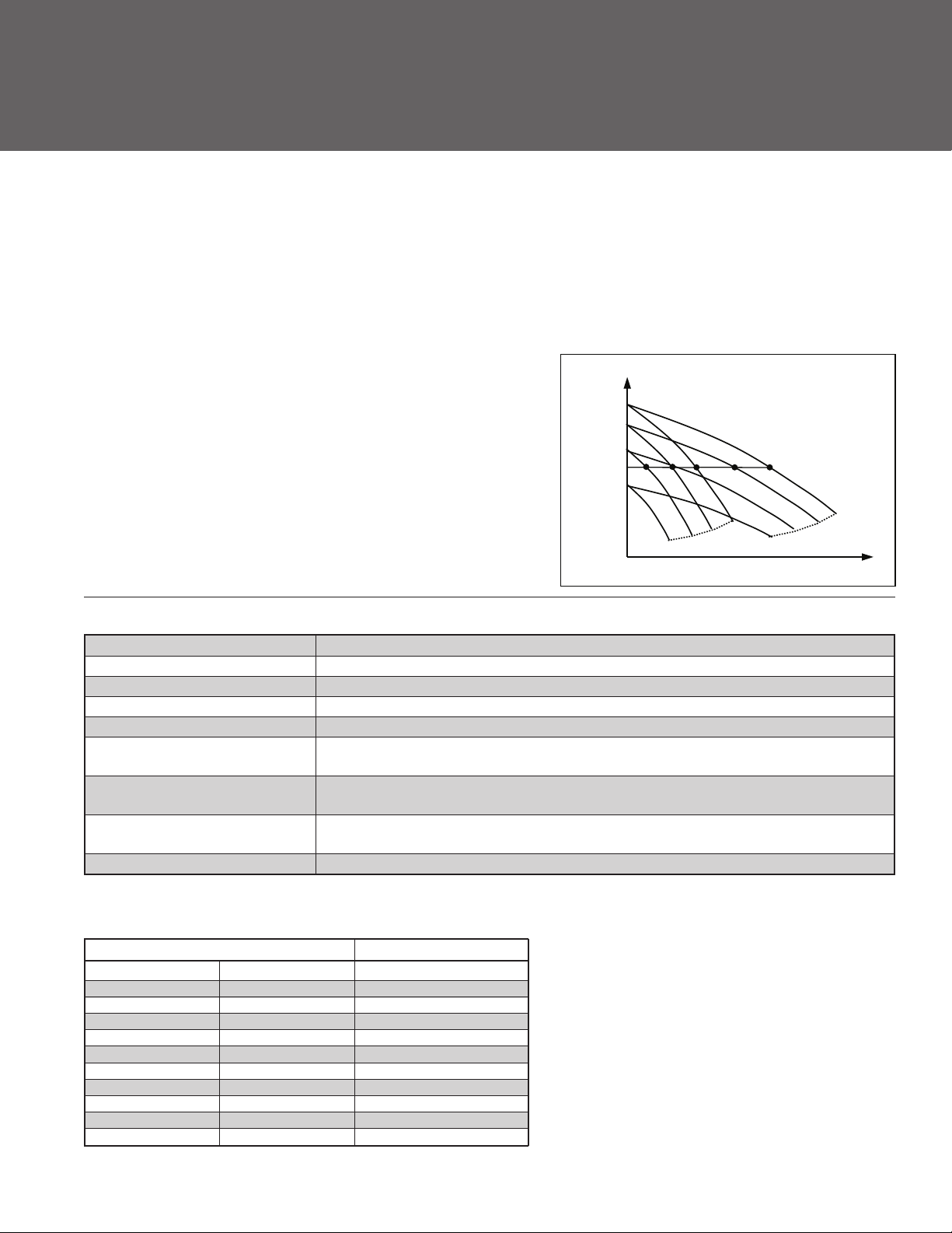
OPERATION DESCRIPTION
SETS WITH VARIABLE-SPEED MOTORS AND PRESSURE TRANSDUCER CONTROL
The starting and stopping of the pumps are determined based on the pressure values set on the controller.
Each frequency converter is connected to a pressure transducer.
The controllers exchange information with each other and provide for cyclic changeover.
The figure shows the operating mode of a two-pump booster set
(Typical Field Set).
• On demand, water is drawn from the tank.
• When the pressure drops belows the PS setting the first pump
starts and the speed is adjusted to maintain a costant pressure as
demand increases.
• If the water consumption increases and the pump reaches
maximum speed, the second pump starts and the speed is adjusted
to maintain constant pressure.
• When demand decreases, the speed is reduced until minimum
speed is reached and one of the pumps are switched off.
• If consumption keeps decreasing the pump slows down, fills the
tank and stops at the pressure setting.
Pressure
Pmax
PS
Figure 3
Duplex
OPERATING CHARACTERISTICS AND LIMITS
Type of pumped liquids Water containing no gas or corrosive and/or aggressive substances
Fluid temperature Above 0° F to 180° F, Pressure transducer limited
Ambient temperature Above 0° F to 104° F, VFD/Display, keep away from direct sun
Maximum operating pressure 360 PSI (Pump without transducer)
Minimum inlet pressure According to NPSH curve and losses, with a minimum margin of 0.5 m
Maximum inlet pressure
than the maximum operating pressure of the set (suction and discharge).
Installation
elevation 3300 feet ASL. Maximum humidity 50% without condensation.
Hourly starts
hour. Variable speed drive starts.
Indoors/outdoors, protected from the direct sun. Away from heat sources. Maximum
Maximum 60 up to 10 HP. Above 10 HP and up to 50 HP, maximum 40 starts per
Sound emission See table
* Note: For higher temperature it is necessary to use special materials (only on request).
The inlet pressure added to the pressure of the pump at zero flow must be lower
Flow
NOISE EMISSION LEVELS
60 Hz 3500 RPM LpA (dB ±4)
HP NEMA Motor Frame PHV
1 56 < 70
2 56 < 70
3 56 < 70
5 145 < 70
7½ 182-184 < 70
10 215 < 70
15 254 73
20 256 75
25 284 75
30 284 75
* Note: Adjusted from 50 Hz data, may vary.
13
Page 14

Goulds Pumps
PHV - Packaged Hydrovar Series
SELECTING A SET
The first thing to do when selecting a package is to determine the quantity of water required and the pressure it must
supply.
CALCULATING THE FLOW RATE
• The quantity of water called water requirement depends on the type of users, e.g. homes, offices, schools, as well
as their number. The theoretic requirement is the total amount of water required by all the users. In actual fact, since it
is very unlikely that there should be a simultaneous demand by all the users, the real requirement is lower than the
theoretic one.
CALCULATING THE HEAD
• The pressure required depends on the type of user. A number of factors must be taken into account, including the
height of the building, the suction conditions and the flow resistance in the pipes.
SELECTING A BOOSTER SET
• According to the required flow rate and head values, it is possible to identify the most suitable type of electric pump.
On two-pump sets the pumps normally act as back-up for one another. A single pump is normally sufficient to
provide for average requirements, while in conditions of high demand the back up pump may be called in to assist.
With the cyclic changeover function duty assignment is rotated to ensure both pumps remain active and with
even running hours, so wear is uniform and the use factor is reduced for longer pump life. This system also ensures
continuity of operation in case one of the pumps needs maintenance.The Hydrovar provides automatic lead/lag,
alternation when programmed in multi-control and wired via RS485 communication terminals.
TANK
• Frequent demand or small system losses determine pressure variations that may be compensated for by using a
tank. Correct selection of a diaphragm tank reduces the number of pump starts and, if it is installed near the
booster set, helps reduce the effect of water hammer, or fast acting flush valves.
The booster sets are ready for installation of diaphragm tanks directly on the delivery manifold, and additional tanks
can be connected to the unused end of the manifold.
For peak performance, variable speed booster sets need smaller tanks compared to traditional systems.
Generally speaking, a tank with a capacity of just 20% of the nominal capacity of a single pump, expressed in gallons
per minute, is required. Example: If my pump is sized for 100 GPM, then we would size a 20 gallon (total capacity)
diaphragm tank.
• Pre-charge the tank with air, 10-15 PSI below your system pressure. Charge dry tank without water pressure or before
installing in system.
14
Page 15
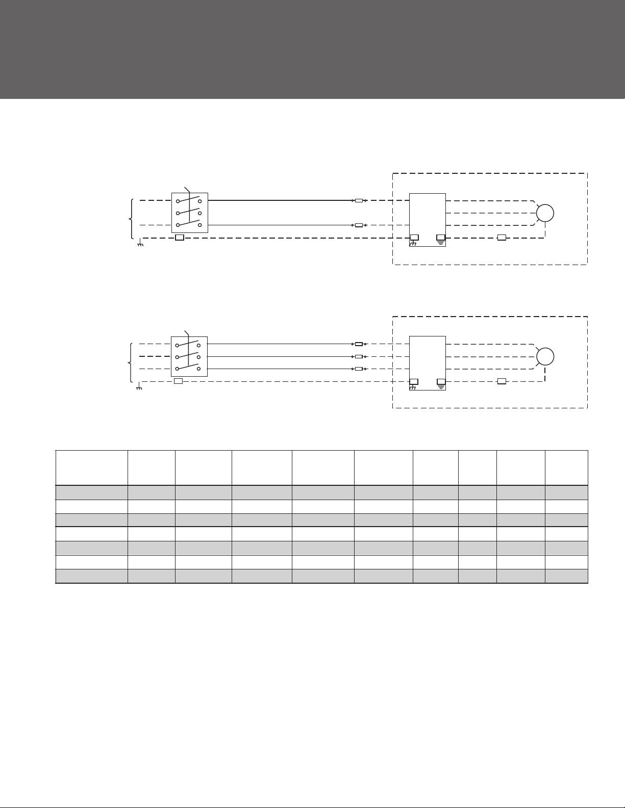
FUSED DISCONNECT BOX:
CUSTOMER SUPPLIED
HYDROVAR
U1
U2
V1
V2
W1
W2
16 AWG
GND
PE
CUSTOMER SUPPLIED
HYDROVAR
U1
U2
V1
V2
W1
W2
16 AWG
GND
PE
MTR
MOTOR
GND
MTR
MOTOR
GND
SINGLE
PHASE
CUSTOMER SUPPLIED
VOLTAGE
THREE
PHASE
CUSTOMER SUPPLIED
VOLTAGE
ITT
Disconnect
Part Number
L1
L2
L1
L2
L3
Input
Voltage
DISCONNECT
1
3
5
DISCONNECT
1
3
5
2
4
6
GND
2
4
6
GND
Disconnect
FUSE BLOCK
12 AWG
12 AWG
FUSE BLOCK
12 AWG
12 AWG
12 AWG
HP / AMP Wire Tightening Fuse AMP Part Voltage
Rating Range Torque Supplier Rating Number Rating
HFD512C1 230/1/60 OT25F3 2 HP / 25A #18-8AWG 7 IN/LB Bussman 20 KTK-R-20 600V
HFD512E1 230/1/60 OT40F3 3 HP / 40A #18-8AWG 7 IN/LB Bussman 30 KTK-R-30 600V
HFD534A1 460/3/60 OT16F3 3 HP / 16A #18-8AWG 7 IN/LB Bussman 10 KTK-R-10 600V
HFD534B1 460/3/60 OT16F3 3 HP / 16A #18-8AWG 7 IN/LB Bussman 15 KTK-R-15 600V
HFD534C1 460/3/60 OT25F3 3 HP / 25A #18-8AWG 7 IN/LB Bussman 20 KTK-R-20 600V
HFD534C2 460/3/60 OT25F3 3 HP / 25A #18-8AWG 7 IN/LB Bussman 20 KTK-R-20 600V
HFD534E2 460/3/60 OT40F3 3 HP / 40A #18-8AWG 7 IN/LB Bussman 30 KTK-R-30 600V
NOTE: Recommended protection (not included with drive only). This fused disconnect is available as part of the PHV series packaged Hydrovar, see price book.
15
Page 16
Goulds Pumps
PHV - Packaged Hydrovar Series
SPECIFICATIONS
Hydrovar VFD Motor
HP Model * Power Supply (V) NEMA Class Install. Power Supply (V) HP
2 HVM1202 1x230 4 TEFC Motor 3x230 2
3 HVM1203 1x230 4 TEFC Motor 3x230 3
3 HVM3403 3x460 4 TEFC Motor 3x460 3
5 HVM3405 3x460 4 TEFC Motor 3x460 5
7½ HVM3407 3x460 4 TEFC Motor 3x460 7½
10 HVM3410 3x460 4 TEFC Motor 3x460 10
15 HVM3415 3x460 4 TEFC Motor 3x460 15
* The new Hydrovar is available single-phase up to 3 HP and 3 HP through 15 HP, 460 volt.
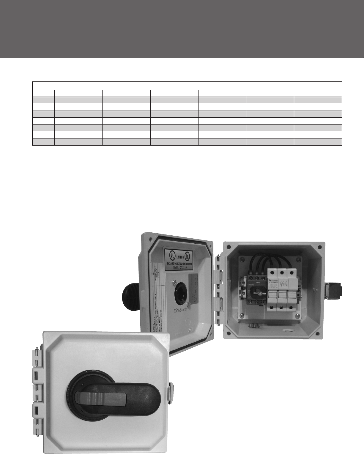
ELECTRICAL PANELS - PHV (Packaged Hydrovar
The GHV sets come with a fused disconnect on which are installed automatic line protection fast acting fuses for
each drive. Class J, 600 volt.
Single-pump sets are supplied as standard with an electrical panel encased in NEMA 4X enclosure, with 2-pole or 3-pole (3
phase) up to 30 amps and featuring a main switch.
The fused disconnect is rated for UL508A.
®
Series)
16
Pump Disconnect Switch
Page 17

MOTOR DATA
3500 RPM, 60 Hz
HP Phase Enclosure
Voltage Frame PN ¹ Class
1
Prem. Eff. TEFC 230/460 56C V06742PE 2.8/1.4 3.12/1.56 12.1 1.25 84.5 B
1½ 3
Prem. Eff. TEFC 230/460 56C V07742PE 4.0/2.0 4.5/2.25 20.1 1.15 85.5 B
2* 3
Prem. Eff. TEFC 208-230/460 56C V08742PE 5/4.75-2.5 6.4-5.8/2.9 30 1.15 86.5 B
3*
Prem. Eff. TEFC 208-230/460 184TC V09742PE 6.8/3.4 8.5-7.7/3.8 32 1.15 88.5 F
5*
Prem. Eff. TEFC 208-230/460 184TC V10742APE 11.2/5.7 14.4-13/6.5 55 1.15 90.2 F
7½* 3
Prem. Eff. TEFC 230/460 213TC V11742APE 17.8/8.9 20.2/10.1 75 1.15 90.2 F
10*
Prem. Eff. TEFC 230/460 215TC V12742PE 23.8/11.9 27.6/13.8 112 1.15 89.5 F
15*
Prem. Eff. TEFC 208-230/460 254TC V13742PE 34.4/17.2 43.8-39.6/19.8 112 1.15 91.7 F
20 3
Prem. Eff. TEFC 208-230/460 256TC V14742PE 46/23 57.5-52/26 201 1.15 92.4 F
25 3
Prem. Eff. TEFC 230/460 284TC V15742PE 56/28 69.9-63.2/31.6 236 1.15 93 F
30 3
Prem. Eff. TEFC 230/460 286TC V16742PE 66/33 83.8-75.8/37.9 281 1.15 93 F
40 3
Prem. Eff. TEFC 230/460 324TSC V17742PE 90/45 102.2/51.1 286 1.15 93.6 F
50 3
Prem. Eff. TEFC 230/460 326TSC V18742SPE 108/54 124.8/62.4 422 1.15 94.1 F
NOTES:
¹ Locked rotor amps are for high voltage only.
* Currently available on Packaged Hydrovar.
• Motors are suitable for AQUAVAR® Variable Speed Drive.
Above data is for Baldor® TC and TSC frame motors. Specications subject to change without notice.
TEFC 230/460 56C V06742 3.7-3.6/1.8 3.99-3.8/1.9 11 1.25 75.5 B
3
TEFC 230/460 56C V07742 4.9-4.6/2.3 5.3-5.1/2.54 18.4 1.15 80 B
TEFC 208-230/460 56C V08742 6.2-5.8/2.9 7.2-6.52/3.26 22 1.15 80 B
TEFC 208-230/460 56C V09742 8.1-7.6/3.8 9.5-8.6/4.3 32.9 1.15 82.5 F
3
TEFC 208-230/460 184TC V10742A 13.2-12/6 15-13.6/6.8 47 1.15 85.5 F
3
TEFC 208-230/460 184TC V11742A 18.5/17.4 21.7-19.6/9.8 94 1.15 88.5 F
TEFC 208-230/460 215TC V12742 25-24/12 30.5-27.6/13.8 105 1.15 85.5 F
3
TEFC 208-230/460 254TC V13742 35/17.5 43-39/19.5 165 1.15 86.5 F
3
TEFC 208-230/460 256TC V14742 46/23 59.3-53.6/26.8 160 1.15 89.5 F
TEFC 230/460 284TC V15742 59/29.5 74.8-67.6/33.8 182 1.15 88.5 F
TEFC 230/460 284TC V16742 68/34 86.7-78.4/39.2 225 1.15 91 F
TEFC 230/460 284TC V17742 90/45 103.2/51.6 322 1.15 90.2 F
TEFC 230/460 326TSC V18742S 112/56
Nameplate NEMA Goulds
FLA SFA
141.8-128.2/64.1
LRA
430 1.15 92.4 F
S.F. Efficiency
Insulation
17
Page 18

Goulds Pumps
PHV - Packaged Hydrovar Series
PERFORMANCE WITH VARYING SPEED FOR CENTRIFUGAL PUMPS
Fitting the electric pump with a variable speed drive makes it possible to vary the pump rotation speed, normally according to the system pressure parameter. Variations in electric pump speed result in modified performances
according to the equivalence relations, called affinity laws.
Head
Flow Rate
Q1=n1
Q2 n2
H
n1
H1
n2
Head
H1=n1
2
H2 n2
H2
B
A
P1=n1
3
Power
n1 = initial speed; n2= speed required.
Q1 = initial flow rate; Q2= flow rate required.
H1 = initial head; H2= head required.
P1 = initial power; P2= power required
Frequency ratios can be used instead of speed in practical applications, keeping 30 Hz as the bottom limit.
Example : 2-pole 50 Hz electric pump n1 =2900 (point A)
Flow rate (A) = 100 l/min; Head (A) = 50m
By reducing the frequency to 30 Hz the speed is reduced to approx. n2 = 1740 rpm (point B)
Flow rate (B) = 60 l/min; Head (B) = 18 m
The power of the new work point B is cut to about 22% of the initial power.
P2 n2
Q1Q2
Q
Flow
SIZING THE DIAPHRAGM TANK IN SYSTEMS WITH SPEED VARIATION
Variable speed booster sets need smaller tanks compared to traditional systems. Generally speaking, a tank with a
capacity of just 20% of the nominal capacity of a single pump, expressed in gallons per minute, is needed. The gradual
starting of the pumps controlled by the drive reduces the need to limit the number of hourly starts; the main purpose
of the tank is to compensate for small system losses, stabilize the pressure and make up for pressure variations caused by
sudden demand (fast acting valves).
Make the following calculation:
Set made up of three electric pumps, each with a maximum flow rate of 100 GPM, for a total capacity of 300 GPM. The
volume required for the tank is 20 gallons. This is total capacity, not drawdown. Mount downstream of the check valves
in discharge manifold.
18
Page 19

VARIABLE SPEED PERFORMANCE CURVES
1SV VARIABLE SPEED CURVE
SSVB 304SS Multi-Stage Pumps MODEL: 1SVB 6 Stage
Hydraulic Data
Maximum Flow Flow at Duty Point Maximum TDH TDH at Duty Point NPSH
22 US GPM 298 feet
Fluid: Water, pure Duty Chart: 3500 RPM
[FT]
Head
300
280
260
240
220
200
180
160
140
120
100
[FT]
[HP]
1.6
1.4
1.2
0.8
0.6
0.4
0.2
6
80
60
40
20
0
NPSH - values
7
6
5
4
3
2
1
0
Shaft power P2
6 (P2)
1
0
0 1 2 3 4 5 6 7 8 9 10 11 12 13 14 15 16 17 18 19 20 21 22 23 24 [US GPM]
Application Range
60 Hz
50 Hz
40 Hz
30 Hz
60 Hz
50 Hz
40 Hz
30 Hz
50 Hz
40 Hz
30 Hz
R
60 Hz
19
Page 20

Goulds Pumps
PHV - Packaged Hydrovar Series
VARIABLE SPEED PERFORMANCE CURVES
1SV VARIABLE SPEED CURVE
SSVB 304SS Multi-Stage Pumps MODEL: 1SVB 9 Stage
Hydraulic Data
Maximum Flow Flow at Duty Point Maximum TDH TDH at Duty Point NPSH
22 US GPM 442 feet
Fluid: Water, pure Duty Chart: 3500 RPM
[FT]
440
400
Head
9
Application Range
R
360
320
280
240
200
160
120
80
40
0
NPSH - values
[FT]
7
6
5
4
3
2
1
0
Shaft power P2
[HP]
2.4
2
1.6
1.2
0.8
0.4
9 (P2)
0
0 1 2 3 4 5 6 7 8 9 10 11 12 13 14 15 16 17 18 19 20 21 22 23 24 [US GPM]
44.5%
44.5%
44.5%
30 Hz
30 Hz
44.5%
60 Hz
50 Hz
40 Hz
60 Hz
50 Hz
40 Hz
60 Hz
50 Hz
40 Hz
30 Hz
20
Page 21

VARIABLE SPEED PERFORMANCE CURVES
1SV VARIABLE SPEED CURVE
SSVB 304SS Multi-Stage Pumps MODEL: 1SVB 15 Stage
Hydraulic Data
Maximum Flow Flow at Duty Point Maximum TDH TDH at Duty Point NPSH
22 US GPM 733 feet
Fluid: Water, pure Duty Chart: 3500 RPM
[FT]
Head
760
720
680
640
600
560
520
480
440
400
360
320
280
240
200
160
120
[FT]
[HP]
3.5
2.5
1.5
0.5
15
44.5%
80
40
0
NPSH - values
7
6
5
4
3
2
1
0
Shaft power P2
4
3
15 (P2)
2
1
0
0 1 2 3 4 5 6 7 8 9 10 11 12 13 14 15 16 17 18 19 20 21 22 23 24 [US GPM]
44.5%
Application Range
44.5%
44.5%
60 Hz
50 Hz
40 Hz
30 Hz
60 Hz
50 Hz
40 Hz
30 Hz
50 Hz
40 Hz
30 Hz
R
60 Hz
21
Page 22

Goulds Pumps
PHV - Packaged Hydrovar Series
VARIABLE SPEED PERFORMANCE CURVES
2SV VARIABLE SPEED CURVE
SSVB 304SS Multi-Stage Pumps MODEL: 2SVB 5 Stage
Hydraulic Data
Maximum Flow Flow at Duty Point Maximum TDH TDH at Duty Point NPSH
40 US GPM 217 feet
Fluid: Water, pure Duty Chart: 3500 RPM
Head
[FT]
220
210
200
190
180
170
160
150
140
130
120
110
100
90
80
70
60
50
40
30
20
10
0
NPSH - values
[FT]
10
8
6
5
57.1%
Application Range
57.1%
30 Hz
57.1%
57.1%
60 Hz
50 Hz
40 Hz
60 Hz
50 Hz
40 Hz
R
4
2
0
Shaft power P2
[HP]
1.6
1.4
1.2
1
0.8
0.6
0.4
0.2
0
5 (P2)
0 2 4 6 8 10 12 14 16 18 20 22 24 [US GPM]
30 Hz
60 Hz
50 Hz
40 Hz
30 Hz
26 28 30 32 34 36 38 40 42
22
Page 23

VARIABLE SPEED PERFORMANCE CURVES
2SV VARIABLE SPEED CURVE
SSVB 304SS Multi-Stage Pumps MODEL: 2SVB 8 Stage
Hydraulic Data
Maximum Flow Flow at Duty Point Maximum TDH TDH at Duty Point NPSH
40 US GPM 353 feet
Fluid: Water, pure Duty Chart: 3500 RPM
[FT]
Head
360
340
320
300
280
260
240
220
200
180
160
140
120
100
80
60
40
20
0
NPSH - values
[FT]
10
8
6
8
57.1%
Application Range
57.1%
30 Hz
57.1%
57.1%
60 Hz
50 Hz
40 Hz
60 Hz
50 Hz
40 Hz
R
4
2
0
Shaft power P2
[HP]
2.4
2
1.6
1.2
0.8
0.4
0
5 (P2)
0 2 4 6 8 10 12 14 16 18 20 22 24 [US GPM]
30 Hz
60 Hz
50 Hz
40 Hz
30 Hz
26 28 30 32 34 36 38 40 42
23
Page 24

Goulds Pumps
PHV - Packaged Hydrovar Series
VARIABLE SPEED PERFORMANCE CURVES
2SV VARIABLE SPEED CURVE
SSVB 304SS Multi-Stage Pumps MODEL: 2SVB 13 Stage
Hydraulic Data
Maximum Flow Flow at Duty Point Maximum TDH TDH at Duty Point NPSH
40 US GPM 586 feet
Fluid: Water, pure Duty Chart: 3500 RPM
[FT]
Head
600
560
520
480
440
400
360
320
280
240
200
160
120
80
40
0
NPSH - values
[FT]
10
8
6
4
2
13
57.1%
Application Range
57.1%
30 Hz
30 Hz
57.1%
57.1%
60 Hz
50 Hz
40 Hz
60 Hz
50 Hz
40 Hz
R
0
[HP]
Shaft power P2
4.5
4
3.5
3
2.5
2
1.5
0.5
13 (P2)
1
30 Hz
0
0 2 4 6 8 10 12 14 16 18 20 22 24 [US GPM]
24
40 Hz
26 28 30 32 34 36 38 40 42
50 Hz
60 Hz
Page 25

VARIABLE SPEED PERFORMANCE CURVES
3SV VARIABLE SPEED CURVE
SSVB 304SS Multi-Stage Pumps MODEL: 3SVB 7 Stage
Hydraulic Data
Maximum Flow Flow at Duty Point Maximum TDH TDH at Duty Point NPSH
78 US GPM 441 feet
Fluid: Water, pure Duty Chart: 3500 RPM
[FT]
440
400
360
320
280
240
200
Head
7
Application Range
60 Hz
R
160
120
80
40
0
NPSH - values
[FT]
12
10
8
6
4
2
0
[HP]
Shaft power P2
7
6
5
4
3
2
1
0
0 4 8 12 16 20 24 [US GPM]
7 (P2)
28 32 36 40
30 Hz
30 Hz
44 48 52 56 60 64 68 72 76 80 84
40 Hz
40 Hz
50 Hz
60 Hz
50 Hz
30 Hz
60 Hz
50 Hz
40 Hz
25
Page 26

Goulds Pumps
PHV - Packaged Hydrovar Series
VARIABLE SPEED PERFORMANCE CURVES
3SV VARIABLE SPEED CURVE
SSVB 304SS Multi-Stage Pumps MODEL: 3SVB 9 Stage
Hydraulic Data
Maximum Flow Flow at Duty Point Maximum TDH TDH at Duty Point NPSH
78 US GPM 565 feet
Fluid: Water, pure Duty Chart: 3500 RPM
Head
[FT]
560
520
480
440
400
360
320
280
240
200
160
120
[FT]
[HP]
9
80
40
0
NPSH - values
12
10
8
6
4
2
0
Shaft power P2
9
8
7
6
5
4
3
2
1
0
0 4 8 12 16 20 24 [US GPM]
9 (P2)
28 32 36 40
Application Range
60 Hz
50 Hz
40 Hz
30 Hz
60 Hz
50 Hz
40 Hz
30 Hz
30 Hz
44 48 52 56 60 64 68 72 76 80 84
R
60 Hz
50 Hz
40 Hz
26
Page 27

VARIABLE SPEED PERFORMANCE CURVES
3SV VARIABLE SPEED CURVE
SSVB 304SS Multi-Stage Pumps MODEL: 3SVB 13 Stage
Hydraulic Data
Maximum Flow Flow at Duty Point Maximum TDH TDH at Duty Point NPSH
78 US GPM 817 feet
Fluid: Water, pure Duty Chart: 3500 RPM
Head
[FT]
800
750
700
650
600
550
500
450
400
350
300
250
200
150
100
[FT]
[HP]
13
50
0
NPSH - values
12
10
8
6
4
2
0
Shaft power P2
12
10
8
6
4
2
0
0 4 8 12 16 20 24 [US GPM]
13 (P2)
28 32 36 40
Application Range
60 Hz
50 Hz
40 Hz
30 Hz
60 Hz
50 Hz
40 Hz
30 Hz
30 Hz
44 48 52 56 60 64 68 72 76 80 84
R
60 Hz
50 Hz
40 Hz
27
Page 28

Goulds Pumps
PHV - Packaged Hydrovar Series
VARIABLE SPEED PERFORMANCE CURVES
4SV VARIABLE SPEED CURVE
SSVB 304SS Multi-Stage Pumps MODEL: 4SVB 2 Stage
Hydraulic Data
Maximum Flow Flow at Duty Point Maximum TDH TDH at Duty Point NPSH
112 US GPM 148 feet
Fluid: Water, pure Duty Chart: 3500 RPM
Head
[FT]
150
140
130
120
110
100
[FT]
[HP]
4.5
3.5
2.5
1.5
0.5
2
90
80
70
60
50
40
30
20
10
0
NPSH - values
14
12
10
8
6
4
2
0
-2
Shaft power P2
4
3
2
1
0
2 (P2)
0 10 20 30 40 50 [US GPM]
Application Range
30 Hz
30 Hz
60 70 80 90
50 Hz
40 Hz
50 Hz
40 Hz
30 Hz
100 110
R
60 Hz
60 Hz
60 Hz
50 Hz
40 Hz
28
Page 29

VARIABLE SPEED PERFORMANCE CURVES
4SV VARIABLE SPEED CURVE
SSVB 304SS Multi-Stage Pumps MODEL: 4SVB 4 Stage
Hydraulic Data
Maximum Flow Flow at Duty Point Maximum TDH TDH at Duty Point NPSH
112 US GPM 299 feet
Fluid: Water, pure Duty Chart: 3500 RPM
Head
[FT]
300
280
260
240
220
200
180
160
140
120
100
[FT]
[HP]
4
80
60
40
20
0
NPSH - values
14
12
10
8
6
4
2
0
-2
Shaft power P2
8
7
6
5
4
3
2
1
0
4 (P2)
0 10 20 30 40 50 [US GPM]
Application Range
30 Hz
30 Hz
60 70 80 90
60 Hz
50 Hz
40 Hz
50 Hz
40 Hz
30 Hz
100 110
R
60 Hz
60 Hz
50 Hz
40 Hz
29
Page 30

Goulds Pumps
PHV - Packaged Hydrovar Series
VARIABLE SPEED PERFORMANCE CURVES
4SV VARIABLE SPEED CURVE
SSVB 304SS Multi-Stage Pumps MODEL: 4SVB 7 Stage
Hydraulic Data
Maximum Flow Flow at Duty Point Maximum TDH TDH at Duty Point NPSH
111 US GPM 526 feet
Fluid: Water, pure Duty Chart: 3500 RPM
Head
[FT]
520
480
440
400
7
Application Range
R
360
320
280
240
200
160
120
80
40
0
NPSH - values
[FT]
14
12
10
8
6
4
2
0
-2
[HP]
Shaft power P2
14
12
10
8
6
4
2
0
7 (P2)
0 10 20 30 40 50 [US GPM]
30 Hz
30 Hz
60 70 80 90
40 Hz
40 Hz
50 Hz
50 Hz
100 110
60 Hz
60 Hz
30 Hz
1205 15 25 35 45 55 65 75 85 95 105 115
60 Hz
50 Hz
40 Hz
30
Page 31

VARIABLE SPEED PERFORMANCE CURVES
33SV VARIABLE SPEED CURVE
SVB CI/316SS Multi-Stage Pumps MODEL: 33SVB 1/1 Stage
Hydraulic Data
Maximum Flow Flow at Duty Point Maximum TDH TDH at Duty Point NPSH
225 US GPM 83 feet
Fluid: Water, pure Duty Chart: 3500 RPM
[FT]
Head
85
STAGE 1/1
80
75
70
65
60
55
50
45
40
35
30
25
20
15
10
5
0
NPSH - values
[FT]
30
25
20
15
10
5
STAGE 1/1
0
Shaft power P2
[HP]
3.5
3
2.5
2
1.5
0.5
STAGE 1/1 (P2)
1
0
0 20 40 [US GPM]
60 80
Application Range
30 Hz
30 Hz
30 Hz
100
120
60 Hz
50 Hz
40 Hz
60 Hz
50 Hz
40 Hz
60 Hz
50 Hz
40 Hz
140 160 180 200 220
R
31
Page 32

Goulds Pumps
PHV - Packaged Hydrovar Series
VARIABLE SPEED PERFORMANCE CURVES
33SV VARIABLE SPEED CURVE
SVB CI/316SS Multi-Stage Pumps MODEL: 33SVB 1 Stage
Hydraulic Data
Maximum Flow Flow at Duty Point Maximum TDH TDH at Duty Point NPSH
224 US GPM 110 feet
Fluid: Water, pure Duty Chart: 3500 RPM
[FT]
Head
115
110
105
100
[FT]
[HP]
4.5
3.5
2.5
1.5
0.5
STAGE 1
95
90
85
80
75
70
65
60
55
50
45
40
35
30
25
20
15
10
5
0
NPSH - values
30
25
20
15
10
5
STAGE 1
0
Shaft power P2
5
4
3
STAGE 1 (P2)
2
1
0
0 20 40 [US GPM]
76.7%
60 80
Application Range
76.7%
30 Hz
30 Hz
30 Hz
100
120
76.7%
60 Hz
76.7%
50 Hz
40 Hz
60 Hz
50 Hz
40 Hz
60 Hz
50 Hz
40 Hz
140 160 180 200 220
R
32
Page 33

VARIABLE SPEED PERFORMANCE CURVES
33SV VARIABLE SPEED CURVE
SVB CI/316SS Multi-Stage Pumps MODEL: 33SVB 2/1 Stage
Hydraulic Data
Maximum Flow Flow at Duty Point Maximum TDH TDH at Duty Point NPSH
225 US GPM 191 feet
Fluid: Water, pure Duty Chart: 3500 RPM
[FT]
Head
200
190
180
170
160
150
140
130
120
110
100
[FT]
[HP]
STAGE 2/1
90
80
70
60
50
40
30
20
10
0
NPSH - values
30
25
20
15
10
5
STAGE 2/1
0
Shaft power P2
9
8
7
6
5
STAGE 2/1 (P2)
4
3
2
1
0
0 20 40 [US GPM]
76.7%
60 80
76.7%
Application Range
30 Hz
30 Hz
30 Hz
100
120
76.7%
76.7%
50 Hz
40 Hz
50 Hz
40 Hz
50 Hz
40 Hz
140 160 180 200 220
60 Hz
60 Hz
60 Hz
R
33
Page 34

Goulds Pumps
PHV - Packaged Hydrovar Series
VARIABLE SPEED PERFORMANCE CURVES
33SV VARIABLE SPEED CURVE
SVB CI/316SS Multi-Stage Pumps MODEL: 33SVB 3/1 Stage
Hydraulic Data
Maximum Flow Flow at Duty Point Maximum TDH TDH at Duty Point NPSH
225 US GPM 310 feet
Fluid: Water, pure Duty Chart: 3500 RPM
[FT]
Head
320
300
280
260
240
220
200
180
160
140
120
100
[FT]
[HP]
STAGE 3/1
80
60
40
20
0
NPSH - values
30
25
20
15
10
5
STAGE 3/1
0
Shaft power P2
14
12
10
8
STAGE 3/1 (P2)
6
4
2
0
0 20 40 [US GPM]
76.7%
60 80
Application Range
76.7%
30 Hz
30 Hz
30 Hz
100
120
76.7%
76.7%
50 Hz
40 Hz
50 Hz
40 Hz
50 Hz
40 Hz
140 160 180 200 220
60 Hz
60 Hz
60 Hz
R
34
Page 35

VARIABLE SPEED PERFORMANCE CURVES
46SV VARIABLE SPEED CURVE
SVB CI/316SS Multi-Stage Pumps MODEL: 46SVB 1/1 Stage
Hydraulic Data
Maximum Flow Flow at Duty Point Maximum TDH TDH at Duty Point NPSH
319 US GPM 100 feet
Fluid: Water, pure Duty Chart: 3500 RPM
[FT]
Head
105
100
[FT]
[HP]
4.5
3.5
2.5
1.5
0.5
STAGE 1/1
95
90
85
80
75
70
65
60
55
50
45
40
35
30
25
20
15
10
5
0
NPSH - values
16
14
12
10
8
6
STAGE 1/1
4
2
0
Shaft power P2
4
STAGE 1/1 (P2)
3
2
1
0
0 20 40 [US GPM]
60 80
77.6%
100
120
Application Range
77.6%
77.6%
40 Hz
30 Hz
40 Hz
30 Hz
40 Hz
30 Hz
140 160 180 200 220
77.6%
60 Hz
50 Hz
60 Hz
50 Hz
60 Hz
50 Hz
240 260 280 300 320 340
R
35
Page 36

Goulds Pumps
PHV - Packaged Hydrovar Series
VARIABLE SPEED PERFORMANCE CURVES
46SV VARIABLE SPEED CURVE
SVB CI/316SS Multi-Stage Pumps MODEL: 46SVB 1 Stage
Hydraulic Data
Maximum Flow Flow at Duty Point Maximum TDH TDH at Duty Point NPSH
319 US GPM 123 feet
Fluid: Water, pure Duty Chart: 3500 RPM
[FT]
Head
130
125
120
115
110
105
100
[FT]
[HP]
STAGE 1
95
90
85
80
75
70
65
60
55
50
45
40
35
30
25
20
15
10
5
0
NPSH - values
16
14
12
10
8
6
STAGE 1/1
4
2
0
Shaft power P2
6
STAGE 1 (P2)
5
4
3
2
1
0
0 20 40 [US GPM]
60 80
100
77.6%
120
Application Range
77.6%
77.6%
40 Hz
30 Hz
40 Hz
30 Hz
40 Hz
30 Hz
140 160 180 200 220
77.6%
60 Hz
50 Hz
60 Hz
50 Hz
60 Hz
50 Hz
240 260 280 300 320 340
R
36
Page 37

TECHNICAL DATA – PUMP HYDRAULICS / MOTOR SIZING
1SV 3500 RPM
Number of
Stages
Draw Motor (1.0 SF) (Feet) (Bar)
22 6.7 7.5 7.5 1100 32.8
20 6.1 7.5 7.5 1005 30.0 580 PSI (40 Bar) CCW
18 5.4 5 7.5 905 27.0
16 4.8 5 5 795 23.7
15 4.6 5 5 742 22.2
13 4 5 5 642 19.2
11 3.4 3 5 550 16.4
9 2.7 3 3 445 13.3
8 2.4 3 3 398 11.9 362 PSI (25 Bar) CW
7 2 2 2 350 10.4
6 1.8 2 2 300 9.0
5 1.5 1.5 1.5 250 7.5
4 1.1 1 1.5 200 6.0
3 0.9 3/4 1 142 4.2
2 0.6 1/2 3/4 100 3.0
2SV 3500 RPM
Number of
Stages
Draw Motor (1.0 SF) (Feet) (Bar)
22 7.7 7.5 NA 950 28.4
20 6.8 7.5 7.5 860 25.7 580 PSI (40 Bar) CCW
18 6.2 7.5 7.5 760 22.7
16 5.3 5 7.5 726 21.7
15 4.9 5 5 680 20.3
13 4.6 5 5 595 17.8
11 4 5 5 500 14.9
9 3.3 3 5 407 12.2
8 2.9 3 3 360 10.7
7 2.4 3 3 315 9.4 362 PSI (25 Bar) CW
6 2.1 2 3 270 8.1
5 1.8 2 2 222 6.6
4 1.5 1.5 1.5 175 5.2
3 1.1 1 1.5 137 4.1
2 0.7 3/4 1 92 2.7
Maximum Motor HP for use Motor HP for use Shutoff Shutoff
HP With 1.15 SF With Hydrovar TDH TDH MAWP Motor Rotation
Maximum Motor HP for use Motor HP for use Shutoff Shutoff
HP With 1.15 SF With Hydrovar TDH TDH MAWP Motor Rotation
3SV 3500 RPM
Number of
Stages
Draw Motor (1.0 SF) (Feet) (Bar)
16 17.6 20 20 1010 30.2
14 15 15 15 894 26.7
13 14 15 15 830 24.8
12 12.8 15 15 760 22.7
11 11.5 10 15 700 20.9
10 10.7 10 15 640 19.1
9 9.7 10 10 575 17.2
8 8.5 7.5 10 505 15.1
7 7.5 7.5 7.5 450 13.4
6 6.5 7.5 7.5 380 11.3
5 5.4 5 7.5 320 9.6
4 4.3 5 5 250 7.5
3 3.3 3 5 190 5.7
2 2.2 2 3 128 3.8
Maximum Motor HP for use Motor HP for use Shutoff Shutoff
HP With 1.15 SF With Hydrovar TDH TDH MAWP Motor Rotation
37
580 PSI (40 Bar) CCW
362 PSI (25 Bar) CW
Page 38

Goulds Pumps
PHV - Packaged Hydrovar Series
TECHNICAL DATA – PUMP HYDRAULICS / MOTOR SIZING
4SV 3500 RPM
Number of
Stages
Draw Motor (1.0 SF) (Feet) (Bar)
12 26.4 25 NA 930 27.8 580 PSI (40 Bar) CCW
10 21.6 20 25 780 23.3
9 19.2 20 20 700 20.9
8 16.9 15 20 620 18.5
7 14.9 15 15 540 16.1
6 12.9 15 15 460 13.7 362 PSI (25 Bar) CW
5 10.7 10 15 390 11.6
4 8.6 7.5 10 305 9.1
3 6.3 7.5 7.5 228 6.8
2 4.3 5 5 150 4.5
33SV 3500 RPM
# of Impellers / Maximum Motor HP for use Motor HP for use Shutoff Shutoff Casing / Sleeve Stages requiring
# reduced HP with 1.15 SF with Hydrovar TDH TDH Pressure rating Thrust Balancing
Diameter Draw Motor (1.0 SF) (Feet) (Bar) (Standard Assy.) Piston
10 54.3 1125 34
10/2 52.8 60 1096 33
10/1 51.3
9 48.8 1012 30
9/1 47.4 983 29
9/2 45.9
8 43.4 900 27
8/1 41.9 871 26 Thrust Piston
8/2 40.5
7 38 787 23
7/1 36.5 758 23
7/2 35 40 729 22
6 32.6 576 20
6/1 31.1 30 646 19
6/2 29.6 617 18
5 27.1 30 562 17
5/1 25.7 25 533 16
5/2 24.2
4 21.7 450 13
4/1 20.2 20 421 13
4/2 18.8 20 392 12 25 Bar (362 PSI)
3 16.3 337 10 1
3/1 14.7 15 310 9
3/2 13.2 15 281 8 Class 125 / 150
2 10.9
2/1 9.4
2/2 7.9 7.5 167 5
1 5.4
1/1 4 5 84 3
1 Pump assembly may be modified for 40 bar (580 psi) application – contact factory.
Maximum Motor HP for use Motor HP for use Shutoff Shutoff
HP With 1.15 SF With Hydrovar TDH TDH MAWP Motor Rotation
Pump Flange
Rating
1066 32
50
954 28
50
842 25 Required
40
504 15
25
225 7
10
7.5 113 3
5
196 6
10
40 Bar (580 PSI)
Class 250 / 300
38
Page 39

TECHNICAL DATA – PUMP HYDRAULICS / MOTOR SIZING
46SV 3500 RPM
# of Impellers / Maximum Motor HP for use Motor HP for use Shutoff Shutoff Casing / Sleeve Stages requiring
# reduced HP with 1.15 SF with Hydrovar TDH TDH Pressure rating Thrust Balancing
Diameter Draw Motor (1.0 SF) (Feet) (Bar) (Standard Assy.) Piston
10/2 77.8 1210 36.1
9 73.2
9/1 71.5 1111 33.2
9/2 69.7
8 65 1010 30.2
8/1 63.3
8/2 61.6 959 28.6 40 Bar (580 PSI)
7 56.9 884 26.4
7/1 55.2 60 858 25.6
7/2 53.4
6 48.8 758 22.6 Required
6/1 47.1 50 732 21.9
6/2 45.3 706 21.1
5 40.7
5/1 38.9
5/2 37.2 580 17.3
4 32.5 505 15.1
4/1 30.8 30
4/2 29 453 13.5
3 24.4 25 379 11.3
3/1 22.7
3/2 20.9 327 9.8
2 16.3 20 253 7.6
2/1 14/5 15
2/2 12.8 200 6.0
1 8.5 10 10 127 3.8
1/1 6.7 7.5 7.5 102 3.0
1137 33.9
75
1085 32.4
75
984 29.4
60
832 24.8 Thrust Piston Class 250 / 300
50
632 18.9
40
25 353 10.5
20
605 18.1
40
479 14.3
30
226 6.7
15
25 Bar (362 PSI)
1
Pump Flange
Rating
Class 125 / 150
66SV 3500 RPM
# of Impellers / Maximum Motor HP for use Motor HP for use Shutoff Shutoff Casing / Sleeve Stages requiring
# reduced HP with 1.15 SF with Hydrovar TDH TDH Pressure rating Thrust Balancing
Diameter Draw Motor (1.0 SF) (Feet) (Bar) (Standard Assy.) Piston
6 73.2 850 25.4
6/1 70.2 75
6/2 67.2 796 23.8
5 61
5/1 58
5/2 55 655 19.6 Required
4 48.8 50 566 16.9
4/1 45.8 50 540 16.1
4/2 42.8
3 36.6
3/1 33.6
3/2 30.6 30 372 11.1
2 24.4 25
2/1 21.4
2/2 18.4 20 230 6.9
1 12.2 15 15 142 4.2
1/1 9.2 10 10 115 3.4
1 Pump assembly may be modified for 40 bar (580 psi) application – contact factory.
707 21.1
60
513 15.3
40
398 11.9
30
257 7.7
20
822 24.5 40 Bar (580 PSI)
75
681 20.3 Thrust Piston Class 250 / 300
60
424 12.7
40
283 8.4
25
25 Bar (362 PSI)
1
39
Pump Flange
Rating
Class 125 / 150
Page 40

Goulds Pumps
PHV - Packaged Hydrovar Series
TECHNICAL DATA
Maximum Inlet Pressure
The following table shows the maximum permissible inlet
pressure. However, the actual inlet pressure + pressure
against a closed valve must always be lower than the
maximum permissible operating pressure.
Pump Number of Stages Maximum Inlet Pressure
17-22 Stages 215 psi (15 bar)
16-22 Stages 215 psi (15 bar)
14-16 Stages 215 psi (15 bar)
11-12 Stages 215 psi (15 bar)
33SV 1-10 Stages
46SV 1-10 Stages
66SV 1-6 Stages
92SV 1-6 Stages
2-16 Stages 145 psi (10 bar)
1SV
2-25 Stages 145 psi (10 bar)
2SV
2-13 Stages 145 psi (10 bar)
3SV
2-10 Stages 145 psi (10 bar)
4SV
215 psi (15 bar)
40
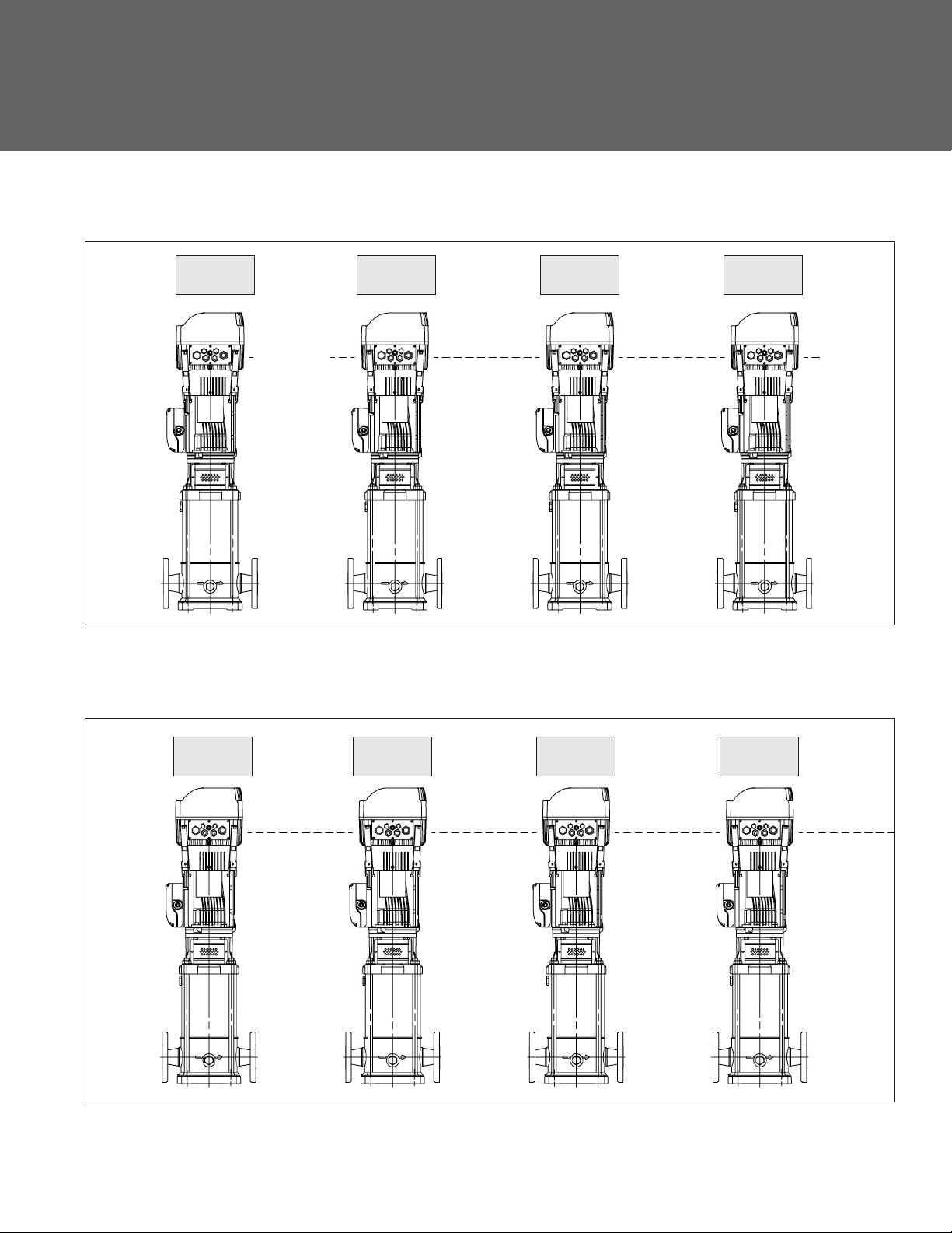
Page 41

PHV — PACKAGED HYDROVAR SERIES — 1SVB
Stage
(ref.) End Box Weight
6
9 3 19.56 13.44 6.70 23.83 30 56 10 5 101
15 182-4TC 5 25.44 15.43 29.71 11.15 6.87 8.50 37 85 137
(3-Phase)
Frame
HP L1
TEFC
2 16.63 12.06 20.90
56C
DI
L2
(max.)
TEFC L6 L7 L8
MI
9.87 5.73 7.19
TEFC
Weights (lb.)
Liquid
27 51 93
TEFC Hydrovar
Disconnect Total
41
Page 42

Goulds Pumps
PHV - Packaged Hydrovar Series
PHV — PACKAGED HYDROVAR SERIES — 2SVB
Stage
(ref.) End Box Weight
5
8 3 18.56 13.88
13
16 26.44 30.71 40 140
(3-Phase)
Frame
HP L1
TEFC
2 15.63 12.06 19.90
56C
182-4TC
23.50
5
DI
L2
(max.)
TEFC L6 L7 L8
27.77
15.44
MI
22.83 5.50 30 56
6.70
9.87
11.15 6.88 8.50
5.75
7.19
Liquid
TEFC
25 51 91
35
Weights (lb.)
TEFC Hydrovar
135
85
Disconnect Total
10 5
100
42
Page 43

PHV — PACKAGED HYDROVAR SERIES — 3SVB
Stage
(ref.) End Box Weight
2 56C 2 15.75 12.06 20.02 9.87 5.75 7.19 33 51 99
4
7 7½ 23.25 6.70 27.52
9 215TC 10 28.88 15.50 33.15 8.06 10.25 47 151 221
13 254TC 15 33.38 16.56 37.65 9.25 10.83 66 250 339
(3-Phase)
Frame
TEFC
182-4TC
HP L1
3 18.75
DI
L2
(max.)
TEFC L6 L7 L8
23.02
15.44
11.15
MI
6.88 8.50
45 124 10 5 184
Liquid
TEFC
37 85 137
Weights (lb.)
TEFC Hydrovar
Disconnect Total
43
Page 44

Goulds Pumps
PHV - Packaged Hydrovar Series
PHV — PACKAGED HYDROVAR SERIES — 4SVB
Stage
(ref.) End Box Weight
2
4 7½ 18.75 6.70 23.02 11.15 39 124 10 5 178
7 254TC 15 24.44 16.56 28.71 9.25 10.31 52 250 325
(3-Phase)
Frame
TEFC
182-4TC
HP L1
5 15.75
DI
L2
(max.)
TEFC L6 L7 L8
20.02
15.44
MI
6.88 8.50
Liquid
TEFC
33 85 133
Weights (lb.)
TEFC Hydrovar
Disconnect Total
44
Page 45

PHV — PACKAGED HYDROVAR SERIES — 33SVB
Stage
(ref.) End Box Weight
1/1
1
2/1 215TC 10 23.58 15.50 16.91 8.06 10.25 143 151
3/1 254TC 15 26.54 16.56 19.87 9.25 10.31 152 250 425
(3-Phase)
Frame
HP L1
TEFC
182-4TC 5 20.62 15.44 13.95 6.88 8.50 132 85 10
DI
L2
(max.)
TEFC L6 L7 L8
6.70
12.27
MI
TEFC
Liquid
Weights (lb.)
TEFC Hydrovar
18
Disconnect Total
317
5
232
45
Page 46

Goulds Pumps
PHV - Packaged Hydrovar Series
PHV — PACKAGED HYDROVAR SERIES — 46SVB
Stage
(ref.) End Box Weight
1/1 182-4TC 7½
1 215TC 10 15.50 6.70 12.27 8.06 10.25 151 5 313
2/1 254TC 15 25.19 16.56 18.52 9.25 10.31 158 250 18 431
(3-Phase)
Frame
TEFC
HP L1
22.19
DI
L2
(max.)
TEFC L6 L7 L8
15.44
15.52
MI
6.88 8.50
TEFC
Liquid
147
124
Weights (lb.)
TEFC Hydrovar
Disconnect Total
286
10
46
Page 47

NPSH
The minimum operating values that can be reached at the
pump suction end are limited by the onset of cavitation.
Cavitation is the formation of vapor-filled cavities within
liquids where the pressure is locally reduced to a critical
value, or where the local pressure is equal to, or just below
the vapor pressure of the liquid.
The vapor-filled cavities flow with the current and when
they reach a higher pressure ares the vapor contained in
the cavities condenses. The cavities collide, generating
pressure waves that are transmitted to the walls. These,
being subjected to stress cycles, gradually become deformed and yield due to fatigue. This phenomenon, characterized by a metallic noise produced by the hammering
on the pipe walls, is called incipient cavitation.
The damage caused by cavitation may be magnified by
electrochemical corrosion and a local rise in temperature
due to the plastic deformation of the walls. The materials
that offer the highest resistance to heat and corrosion are
alloy steels, especially austenitic steel. The conditions that
trigger cavitation may be assessed by calculating the total
net suction head, referred to in technical literature with
the acronym NPSH (Net Positive Suction Head).
The NPSH represents the total energy (expressed in feet) of
the liquid measured at suction under conditions of incipient cavitation, excluding the vapor pressure (expressed in
feet) that the liquid has at the pump inlet.
The maximum possible suction head for installation depends on the value of the atmospheric pressure (i.e. the
elevation above sea level at which the pump is installed)
and the temperature of the liquid.
To help the user, with reference to water temperature
(40ºF) and to the elevation above sea level, the following
tables show the drop in hydraulic pressure head in relation
to the elevation above sea level, and the suction loss in
relation to temperature.
Water
Temperature (°C)
Suction
Loss (ft)
Elevation Above
Sea Level (ft)
Suction
Loss (ft)
68 104 140 176 194 230 248
-.7 2.3 6.6 16.4 24.3 50.5 70.5
1600 3300 4900 6500 8200 9800
1.8 3.6 5.4 7.2 9.0 10.8
To reduce it to a minimum, especially in cases of high suction head (over 13 – 16 feet) or within the operating limits
with high flow rates, we recommend using a suction line
having a larger diameter than that of the pump’s suction
port. It is always a good idea to position the pump as close
as possible to the liquid to be pumped.
To find the static height (hz) at which to install the machine under safe conditions, the following formula must
be verified:
hp + hz ≥ (NPSHr + 2 feet) + hf + h
pv
where:
hp is the absolute pressure applied to the free liquid sur-
face in the suction tank, expressed in feet of liquid; hp
is the quotient between the barometric pressure and
the specific weight of the liquid.
hz is the suction lift between the pump axis and the free
liquid surface in the suction tank, expressed in feet;
hz is negative when the liquid level is lower than the
pump axis.
hf is the flow resistance in the suction line and its acces-
sories, such as: fittings, foot valve, gate valve, elbows,
etc.
hpv is the vapor pressure of the liquid at the operating
temperature, expressed in feet of the liquid. hpv is
the quotient between the Pv vapor pressure and the
liquid‘s specific weight.
0.5 is the safety factor.
47
Page 48

Goulds Pumps
PHV - Packaged Hydrovar Series
TECHNICAL DATA – WATER PROPERTY CHART
Temp ºF Temp ºC
(Cubic ft/lb) @ 39.2ºF @ 60ºF @ 68ºF (lb/cubic ft) (psi Abs)
32 0.0 0.01602 1.000 1.001 1.002 62.42 0.088
35 1.7 0.01602 1.000 1.001 1.002 62.42 0.100
40 4.4 0.01602 1.000 1.001 1.002 62.42 0.122
50 10.0 0.01603 0.999 1.001 1.002 62.38 0.178
60 15.6 0.01604 0.999 1.000 1.001 62.34 0.256
70 21.1 0.01606 0.998 0.999 1.000 62.27 0.363
80 26.7 0.01608 0.996 0.998 0.999 62.19 0.507
90 32.2 0.0161 0.995 0.996 0.997 62.11 0.698
100 37.8 0.01613 0.993 0.994 0.995 62.00 0.949
120 48.9 0.0162 0.989 0.990 0.991 61.73 1.692
140 60.0 0.01629 0.983 0.985 0.986 61.39 2.889
160 71.1 0.01639 0.977 0.979 0.979 61.01 4.741
180 82.2 0.01651 0.970 0.972 0.973 60.57 7.510
200 93.3 0.01663 0.963 0.964 0.966 60.13 11.526
212 100.0 0.01672 0.958 0.959 0.960 59.81 14.696
220 104.4 0.01677 0.955 0.956 0.957 59.63 17.186
240 115.6 0.01692 0.947 0.948 0.949 59.10 24.97
260 126.7 0.01709 0.938 0.939 0.940 58.51 35.43
280 137.8 0.01726 0.928 0.929 0.930 58.00 49.20
300 148.9 0.01745 0.918 0.919 0.920 57.31 67.01
320 160.0 0.01756 0.908 0.909 0.910 56.66 89.66
340 171.1 0.01787 0.896 0.898 0.899 55.96 118.01
360 182.2 0.01811 0.885 0.886 0.887 55.22 153.04
380 193.3 0.01836 0.873 0.874 0.875 54.47 195.77
400 204.4 0.01864 0.859 0.860 0.862 53.65 247.31
420 215.6 0.01894 0.846 0.847 0.848 52.80 308.83
440 226.7 0.01926 0.832 0.833 0.834 51.92 381.59
460 237.8 0.0196 0.817 0.818 0.819 51.02 466.9
480 248.9 0.02 0.801 0.802 0.803 50.00 566.1
500 260.0 0.0204 0.785 0.786 0.787 49.02 680.8
520 271.1 0.0209 0.765 0.766 0.767 47.85 812.4
540 282.2 0.0215 0.746 0.747 0.748 46.51 962.5
560 293.3 0.0221 0.726 0.727 0.728 45.30 1133.1
580 304.4 0.0228 0.703 0.704 0.704 43.90 1325.8
600 315.6 0.0236 0.678 0.679 0.680 42.30 1542.9
620 326.7 0.0247 0.649 0.650 0.650 40.50 1786.6
640 337.8 0.026 0.617 0.618 0.618 38.50 2059.7
660 348.9 0.0278 0.577 0.577 0.578 36.00 2365.4
680 360.0 0.0305 0.525 0.526 0.527 32.80 2708.1
700 371.1 0.0369 0.434 0.435 0.435 27.10 3093.7
Specific Volume Specific Gravity Weight Vapor Pressure
48
Page 49

VOLUMETRIC CAPACITY
Litres Cubic metres Cubic feet Cubic feet Imp. gal. US gal.
per minute per hour per hour per minute per minute per minute
l/min m3/h ft3/h ft3/min Imp. gal/min Us gal./min
1,0000 0,0600 2,1189 0,0353 0,2200 0,2640
16,6670 1,0000 35,3147 0,5886 3,6660 4,4030
0,4720 0,0283 1,0000 0,0167 0,1040 0,1250
28,3170 1,6990 60,0000 1,0000 6,2290 7,4800
4,5460 0,2728 9,6326 0,1605 1,0000 1,2010
3,7850 0,2271 8,0209 0,1337 0,8330 1,0000
0,1100 0,0066 0,2339 0,0039 0,0240 0,0290
PRESSURE AND HEAD
Newtons per kilopascal bar Pound force metre millimetre
square metre per square inch of water of mercury
N/m2 kPa bar psi m H2O mm Hg
1,0000 0,0010 1 x 10⁵ 1,45 x 10⁻⁴ 1,02 x 10⁻⁴ 0,0075
1000,0000 1,0000 0,0100 0,1450 0,1020 7,5000
100000,0000 100,0000 1,0000 14,5000 10,2000 750,1000
98067,0000 98,0700 0,9810 14,2200 10,0000 735,6000
6895,0000 6,8950 0,0690 1,0000 0,7030 51,7200
2984,0000 2,9840 0,0300 0,4330 0,3050 22,4200
9789,0000 9,7890 0,0980 1,4200 1,0000 73,4200
133,3000 0,1330 0,0013 0,0190 0,0140 1,0000
3386,0000 3,3860 0,0338 0,4910 0,3450 25,4000
LENGTH
millimetre centimetre metre inch foot yard
mm cm m in ft yd
1,0000 0,1000 0,0010 0,0394 0,0033 0,0011
10,0000 1,0000 0,0100 0,3937 0,0328 0,0109
1000,0000 100,0000 1,0000 39,3701 3,2808 1,0936
25,4000 2,5400 0,0254 1,0000 0,0833 0,0278
304,8000 30,4800 0,3048 12,0000 1,0000 0,3333
914,4000 91,4400 0,9144 36,0000 3,0000 1,0000
VOLUME
cubic metre litre millilitre imp. gallon US gallon cubic foot
m3 litre ml imp. gal. US gal. ft
1,0000 1000,0000 1 x 10⁶ 220,0000 264,2000 35,3147
0,0010 1,0000 1000,0000 0,2200 0,2642 0,0353
1 x 10⁻⁶ 0,0010 1,0000 2,2 x 10⁻⁴ 2,642 x 10-4 3,53 x 10⁻⁵
0,0045 4,5460 4546,0000 1,0000 1,2010 0,1605
0,0038 3,7850 3785,0000 0,8327 1,0000 0,1337
0,0283 28,3170 28317,0000 6,2288 7,4805 1,0000
3
49
Page 50

Goulds Pumps
PHV - Packaged Hydrovar Series
NOTES
50
Page 51

NOTES
51
Page 52

ITT
2881 East Bayard Street, Seneca Falls, NY 13148
Phone: (315) 568-7123 • Fax: (315) 568-7973
www.goulds.com
Goulds Pump s and G&L are regis tere d tr ademarks of ITT Corporation. I TT, th e En gineered Blocks
Symbol and Engineered for Life are reg istered trademarks of I TT Manu fact uring Enterprises, Inc.
Copy right © 2009 ITT Corpor ation BPHV S eptembe r, 200 9 Printe d in U. S.A.
SPEC IFICATIO NS ARE SUBJE CT TO CHANGE WITHO UT NOT ICE.
ITT
Engineered for life
 Loading...