

ITT Bell & Gossett Aquastat Series, Bell & Gossett AQS-1/2, Bell & Gossett TC-1, Bell & Gossett AQS-3/4 Installation, Operation & Service Instructions

Bell & Gossett
Instruction Manual P58749
Bell & Gossett
Automatic Timer Kit Model TC-1
REVISION B
Aquastat Models AQS-
1
/2, AQS-3/4
Pumps With Plug-In Cords
Installation, Operation & Service Instructions
INSTALLER: PLEASE LEAVE THIS MANUAL FOR THE OWNER’S USE.
SAFETY
INSTRUCTIONS
This safety alert symbol will be used in this manual and on the
pump Safety Instruction decal to draw attention to safety related
instructions. When used, the safety alert symbol means ATTENTION! BECOME ALERT! YOUR SAFETY IS INVOLVED!
FAILURE TO FOLLOW THE INSTRUCTIONS MAY RESULT IN
A SAFETY HAZARD.
APPLICATION
To increase the overall efficiency of a hot water recirculation
system, the TC-1 timer control kit and the AQSaquastat kits can be installed for use on any B&G NRF, NBF or
Series PL circulator. The TC-1 timer control is programmable
to turn the circulator ON and OFF automatically at preset
times. The aquastat kits switch the pump OFF at 120°F
(48.9°C) and ON at 100°F (37.8°C). The timer and aquastat kits
can be used in combination or they can be used separately.
This permits the user to have the pump circulate hot water
only during those times when high usage can be expected
throughout the day. When the aquastat kit and timer are used
together, the pump will only circulate water when the ON time
conditions are met and when the water temperature is low
enough to cause the aquastat to switch ON.
1
/2 and AQS-3/4
OPERATIONAL LIMITS
For use on B&G models NRF/NBF/Series PL, indoor use only
Power supply: 115-120 VAC, 60Hz, 1Ø
Minimum switch interval: 15 minutes
Run Modes: ON (continuous run), OFF (off at all times), TIMER
(run at programmed intervals)
Maximum switch current: 16 amps
Aquastat switch modes: OFF (open) at 120°F (48.9°C) and ON
(closed) at 100°F (37.8°C)
Aquastat type: Bimetal element, senses surface temperature
of outside diameter of pipe
1
Pipe Size: AQS-
Mounting: May be installed to sense temperature at the suction or discharge pipe of the pump
NOTE! Aquastat operation is dependent on ambient evironment. In installations with excessive heat gain or loss in the
ambient may affect the on/off operating temperatures.
/2 clips onto 1/2" copper pipe or 3/8" steel pipe
(OD of pipe
AQS-
(OD of pipe
5
/8")
3
/4 clips onto 3/4" copper pipe or 1/2" steel pipe
7
/8")
TIMER INSTALLATION
1. Disconnect the electrical supply to the pump.
WARNING: ELECTRICAL SHOCK HAZARD
Disconnect and lock out the power before making
electrical connections. Failure to follow these instructions
could result in serious personal injury or death.
2. Remove the screw that holds the steel conduit box cover
to the pump.
3. Remove the conduit box cover. The timer assembly replaces
the conduit box cover.
4. Disconnect the black and white motor leads from the power
supply.
5. Position the plastic base for the timer assembly onto the
steel conduit box with the warning/caution label to the rear
of the pump.
6. Secure the plastic timer base to the conduit box with one
8-32 screw provided.
7. Verify that the electrical rating of the timer matches the
values shown on the nameplate of the circulator.
8. Make the electrical connections according to the wiring
diagram provided. (See Figure 2)
. Position the cover/timer assembly over the base while
9
insuring that all wires are inside the box. Note that the
cover/timer assembly can only be assembled in one direction on the base. Line up the screw holes in the cover with
the screw holes in the base.
10. Fasten the cover to the base using (2) 8-32 screws provided.
AQUASTAT INSTALLATION
1. Follow steps 1 and 2 in the timer installation section.
2. Remove the conduit box cover. If the aquastat is installed
without the timer, the steel cover is reassembled on the
ump after the aquastat installation is complete.
p
3. Fasten the aquastat clip to the discharge or suction pipe of
the pump.
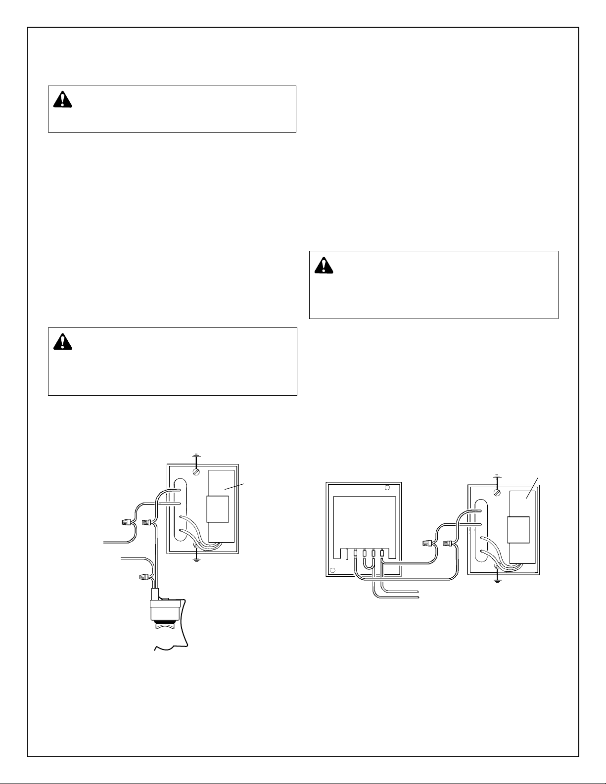
4. Make the electrical connections according to the wiring
diagram provided. (See Figure 1)
WARNING: ELECTRICAL SHOCK HAZARD
Electrical connections are to be made by a qualified
electrician in accordance with all applicable codes, ordinances and good practices. Failure to follow these instructions could result in serious personal injury, death and/or
property damage.
WARNING: ELECTRICAL SHOCK HAZARD
Electrical connections are to be made by a qualified
electrician in accordance with all applicable codes, ordinances and good practices. Failure to follow these instructions could result in serious personal injury, death and/or
property damage.
CAPACITOR
N
WHITE
L
BLACK
WHITE
BLACK
AQUASTAT
5. Reassemble the conduit box cover to the conduit box while
insuring that all wires are inside the box. Reinstall the 8-32
screw to secure the cover to the conduit box.
CAPACITOR
BLACK
TIMER
54 3 2 1
WHITE
BLACK
WHITE
WHITE
BLACK
L
FIGURE 2
FIGURE 1
2
 Loading...