

Page 1

Industrial Process
Maintenance Manual
Advantage® Actuator 2.0
Page 2

Page 3

Table of Contents
Introduction and Safety...................................................................................................................................................2
Safety message levels.........................................................................................................................................................2
User health and safety.......................................................................................................................................................2
Product Description..........................................................................................................................................................4
Actuator identification......................................................................................................................................................4
Bonnet description............................................................................................................................................................5
Valve diaphragm identification........................................................................................................................................6
Maintenance........................................................................................................................................................................7
Precautions.........................................................................................................................................................................7
Inspection...........................................................................................................................................................................7
Tighten the bonnet fasteners...........................................................................................................................................7
Fastener torque table for valve body to topworks....................................................................................................8
Disassemble the valve.......................................................................................................................................................8
Replace the valve diaphragm...........................................................................................................................................9
Adjust the travel (closing) stop......................................................................................................................................12
Replace the spindle o-rings............................................................................................................................................12
Lubrication requirements...............................................................................................................................................12
Replace the actuator diaphragm and spring for fail open actuator..........................................................................13
Replace the actuator diaphragm and spring for fail close actuator..........................................................................14
Replace the actuator diaphragm for double acting actuator.....................................................................................15
Tighten the actuator cover to cover fasteners............................................................................................................15
Fastener torque table for actuator cover to cover...................................................................................................15
Table of Contents
Parts Listing and Cross-Sectional Drawings...........................................................................................................16
Advantage actuator series 3, 5, 8, and 16 parts...........................................................................................................16
Parts for fixture ..............................................................................................................................................................17
Advantage® Actuator 2.0 Maintenance Manual 1
Page 4

Introduction and Safety
Introduction and Safety
Safety message levels
Definitions
Safety message level Indication
DANGER:
WARNING:
CAUTION:
A hazardous situation which, if not avoided, will
result in death or serious injury
A hazardous situation which, if not avoided, could
result in death or serious injury
A hazardous situation which, if not avoided, could
result in minor or moderate injury
NOTICE:
User health and safety
General precautions
This product is designed and manufactured using good workmanship and materials, and meets all
applicable industry standards. This product should be used only as recommended by an ITT engineer.
WARNING:
• Misapplication of the valve can result in injury or property damage. Select valves and valve
components of the proper materials and make sure that they are consistent with your specific
performance requirements. Incorrect application of this product includes but is not limited to:
• Exceeding the pressure or temperature rating
• Failing to maintain this product according to the recommendations
• Using this product to handle caustic or hazardous substances that it is not designed to handle
Electrical Hazard:
The possibility of electrical risks if instructions are
not followed in a proper manner
• A potential situation which, if not avoided,
could result in an undesirable result or state
• A practice not related to personal injury
Qualifications and training
The personnel responsible for the assembly, operation, inspection, and maintenance of the valve must be
appropriately qualified. The operating company must do the following tasks:
• Define the responsibilities and competency of all personnel handling this equipment.
• Provide instruction and training.
• Ensure that the contents of the operating instructions have been fully understood by the personnel.
2 Advantage® Actuator 2.0 Maintenance Manual
Page 5

Instruction and training can be carried out by either ITT or the reseller of the valve by order of the
operating company.
Non-compliance risks
Failure to comply with all safety precautions can result in the following conditions:
• Death or serious injury due to electrical, mechanical, and chemical influences
• Environmental damage due to the leakage of dangerous materials
• Product damage
• Property damage
• Loss of all claims for damages
Operational safety precautions
Be aware of these safety precautions when operating this product:
• Do not leave hot or cold components of the product unsecured against contact if they are a source of
danger.
• Do not remove the contact guard for moving parts when the product is in operation. Never operate
the product without the contact guard installed.
• Do not hang items from the product. Any accessories must be firmly or permanently attached.
• Do not use the product as a step or hand hold.
• Do not paint over the identification tag, warnings, notices, or other identification marks associated
with the product.
Introduction and Safety
Maintenance safety precautions
Be aware of these safety precautions when performing maintenance on this product:
• You must decontaminate the product if it has been exposed to harmful substances such as caustic
chemicals.
• You must immediately fit or reactivate all safety and protective equipment upon completion of work.
Use of unauthorized parts
Reconstruction or modification of the product is only permissible after consultation with ITT. Genuine
spare parts and accessories authorized by ITT serve to maintain safety. Use of non-genuine ITT parts can
annul liability of the manufacturer for the consequences. ITT parts are not to be used in conjunction with
products not supplied by ITT as this improper use can annul all liability for the consequences.
Unacceptable modes of operation
The operational reliability of this product is only guaranteed when it is used as designated. The operating
limits given on the identification tag and in the data sheet may not be exceeded under any circumstances. If
the identification tag is missing or worn, contact ITT for specific instructions.
Advantage® Actuator 2.0 Maintenance Manual 3
Page 6

Product Description
Product Description
Actuator identification
Design Overview
The actuator is a spring or double acting pneumatic actuator.
To determine if you have an Advantage actuator or an Advantage actuator 2.0 locate the spindle
compressor connection and determine if you have a pin or t-slot connection.
Figure 1: Pin connection for Advantage
actuator
Figure 2: T-slot Connection for Advantage
actuator 2.0
Model number
The actuator model number is located on the ITT identification tag. The model number is a four digit
number defining the actuator as follows.
Table 1: Actuator
Code Description
B Advantage actuator 2.0
Table 2: Mode of operation
Code Description
1 Fail open (spring to open, air to close) (direct acting)
2 Fail close (spring to close, air to open) (reverse
acting)
3 Double acting (air to open, air to close)
Table 3: Actuator series
Code
1
Actuator series
2
03, 04 3
05, 06 5
08, 09 8
15, 16, 17 16
Table 4: Examples
Model number Description
B308 Advantage actuator 2.0, double acting, series 8
B215 Advantage actuator 2.0, fail close, series 16 with a 15
spring set
1
For fail close actuators, codes are specific spring combinations.
2
Series number equates to diaphragm effective area.
4 Advantage® Actuator 2.0 Maintenance Manual
Page 7
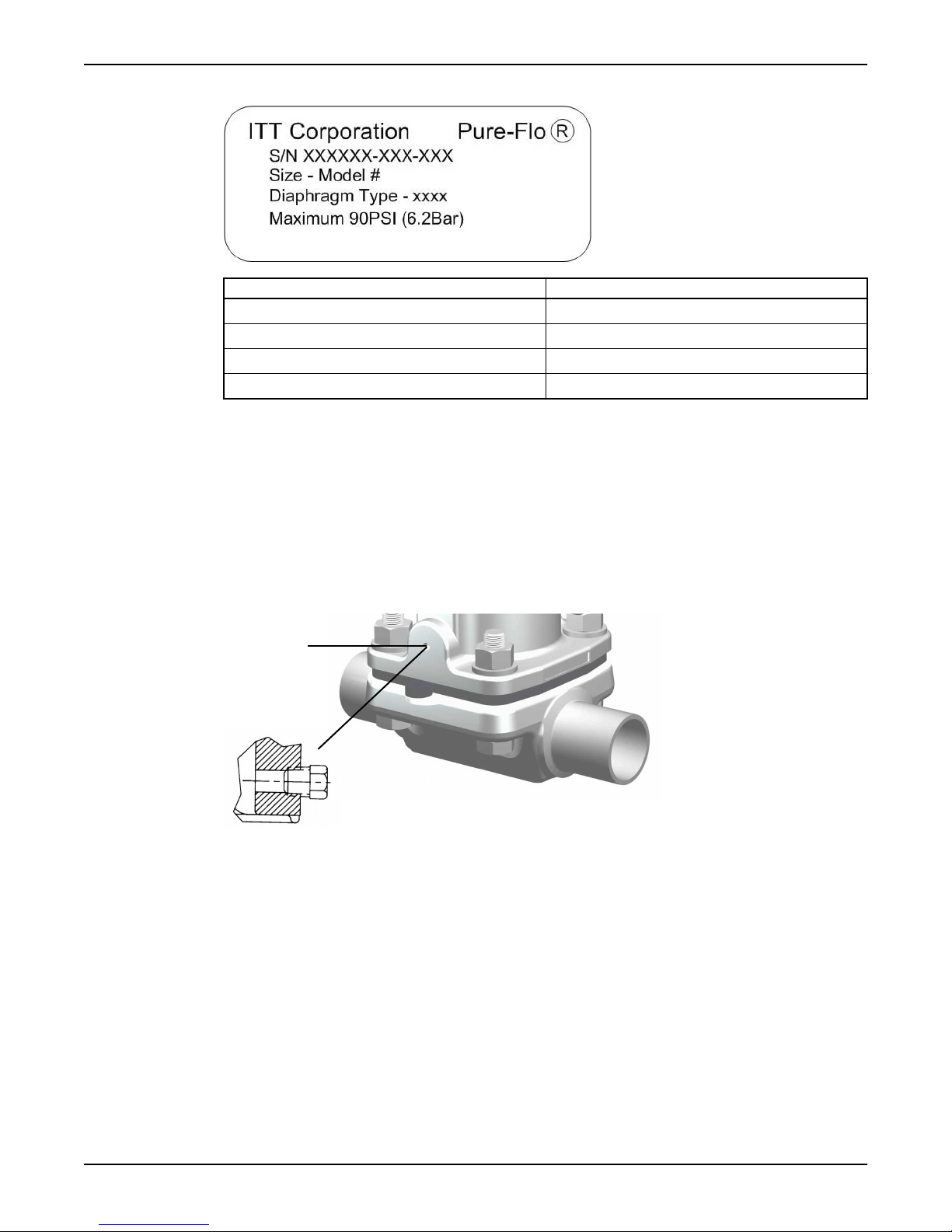
Identification tag
Bonnet
weep hole
V-notch vent plug
(Sealed bonnet only)
Line Description
1 Valve serial number
2 Valve size and model number
3 Valve diaphragm type
4 Maximum recommended actuation pressure
Bonnet description
Non-Sealed bonnet
The non-sealed bonnet has a weep hole that permits leakage of the process fluid if the diaphragm
ruptures.
Product Description
Sealed bonnet
The sealed bonnet uses a special “V-notch” vent plug, which permits diaphragm inspection.
Figure 3: Weep hole and V-notch vent plug
Advantage® Actuator 2.0 Maintenance Manual 5
Page 8

Supplier code
Date code
Grade of
diaphragm
Valve size
Date code
Material code
Product Description
Valve diaphragm identification
Diaphragm tab codes
All diaphragm materials and physical properties are batch traceable via permanent codes molded into the
diaphragm tabs. The molding date, grade of diaphragm, and valve size provide traceability to original batch
records.
Figure 4: Elastomer diaphragm front
Figure 5: Elastomer diaphragm back
Figure 6: PTFE diaphragm
6 Advantage® Actuator 2.0 Maintenance Manual
Page 9

Maintenance
Precautions
WARNING:
• All procedures must be performed by qualified personnel.
• When the process fluid is hazardous, thermal (hot or cold), or corrosive, take extra precautions.
Employ the appropriate safety devices and be prepared to control a process media leak.
• Always wear protective clothing and equipment to safeguard the eyes, face, hands, skin, and lungs
from the particular fluid in the line.
CAUTION:
• Disconnect electrical, pneumatic, and hydraulic power before servicing actuator or automation
components.
Inspection
Inspection area What to look for Action if problem is found
External valve parts Excessive wear or corrosion
Maintenance
• Replace the affected parts
• Contact ITT to obtain
replacement parts or for
specific instructions
Non sealed bonnet Fluid weeping from the plug Replace the valve diaphragm
Sealed bonnet Fluid weeping from the plug
Actuator's bonnet weep hole and
air ports
Topworks Spindle binding, excessive noise,
Diaphragm and valve body Leakage between the diaphragm
For more information, see:
• Replace the valve diaphragm in this manual.
• Replace the spindle o-rings in this manual.
• Lubrication requirements in this manual.
• Tighten the bonnet fasteners in this manual.
Tighten the bonnet fasteners
CAUTION:
Do not tighten fasteners while the system is pressurized or at elevated temperatures (greater than 100°F
(38°C)).
Replace the valve diaphragm
Loosen the v-notch vent plug 2-3
turns to check
Air pressure
Lubricate the actuator
or dried lubricant
Tighten the bonnet fasteners
and valve body
1. Depressurize the system.
2. Use regulated air pressure to position diaphragm so that valve is slightly open.
You may need to use air pressure to actuate the valve.
Advantage® Actuator 2.0 Maintenance Manual 7
Page 10

Maintenance
3. Tighten the bonnet fasteners in a crisscross pattern.
For more information, see Fastener torque table for valve body to topworks in this manual.
4. Make multiple crisscross passes to build up torque to the final table value. Make additional crisscross
passes using final table values to evenly tighten each fastener to within 5% of torque value.
5. Retighten the bonnet fasteners as noted above at ambient conditions after the system has cycled
through operating pressure and temperature.
6. Monitor the valve for leakage:
If leakage ... Then ...
Occurs at the body/bonnet
flange sealing area
Continues Depressurize the system and retighten the bonnet fasteners as
Continues Replace the valve diaphragm.
For more information, see Replace the valve diaphragm in this manual.
Depressurize the system and retighten the bonnet fasteners as
noted above.
noted above. (maximum 3rd re-torque)
Fastener torque table for valve body to topworks
Values given are for lubricated fasteners.
Valve size Bolt size PTFE diaphragm Elastomer diaphragm
Inch DN Imperial Metric in-lb N-m in-lb N-m
0.50 15 1/4" M6 25-60 2.8-6.8 20-40 2.3-4.5
0.75 20 1/4" M6 50-65 5.7-9.1 20-50 2.3-5.7
1.00 25 5/16" M8 65-90 7.4-11.3 45-70 5.1-7.9
1.50 40 3/8" M10 200-225 23-25 75-130 8.5-14.7
2.00 50 7/16" M12 225-275 25-31 100-180 11-20
Guidelines
• Minimum values given will provide a longer diaphragm cycle life for valves in non-autoclave and low
thermal cycle conditions.
• Maximum values given may be necessary for autoclave conditions and for high thermal cycle
conditions.
• Torques should be applied at near ambient conditions (less than 100ºF (38ºC)).
Disassemble the valve
1. Remove all line pressure.
2. Do you have a switch package?
• If yes: Proceed to step 3.
• If no: Proceed to step 5.
3. Do you have a fail open or double acting actuator?
• If yes: Proceed to step 4.
• If no: Proceed to step 5.
4. Do you have a series 33 actuator or adjustable opening stop?
• If yes: Remove the switch package.
• If no: Proceed to step 5.
5. If the actuator mode of operation is fail open or fail close, then load the actuator with air.
If the actuator mode of
operation is ...
Fail open Load the air port in the upper cover of the actuator with sufficient air
Then ...
to partially close the valve.
8 Advantage® Actuator 2.0 Maintenance Manual
Page 11

Maintenance
If the actuator mode of
operation is ...
Fail close Load the air port in the bottom cover of the actuator with sufficient air
6. Remove the bonnet fasteners.
7. Lift the topworks assembly from the valve body.
8. If the actuator mode of operation is fail open, then remove pressure load from the actuator.
9. Do you have a fail open or double acting actuator?
• If yes: Proceed to step 10.
• If no: Procedure is complete.
10. Do you have a series 33 actuator or adjustable opening stop?
• If yes: When the actuator is not on the valve body, do not allow the flats on the indicating spindle
to move below the upper cover spindle o-ring.
• If no: Procedure is complete.
Replace the valve diaphragm
1. Disassemble the valve.
For more information, see Disassemble the valve in this manual.
2. If the actuator mode of operation is fail open, pressurize the actuator by applying air to the upper
cover, slightly extending the compressor and diaphragm.
3. Unscrew the diaphragm from the compressor by turning the diaphragm counterclockwise.
The replacement diaphragm should be identical in size and grade to the original diaphragm.
4. Insert the tube nut by sliding the flat end into the actuator spindle so that it rests flush in the slot.
5. Put the compressor over top of the tube nut.
6. If replacing a PTFE diaphragm, follow these steps.
a) Install the new elastomer backing cushion over the tube nut.
Then ...
to partially open the valve.
b) Invert the PTFE diaphragm by pressing the center of the diaphragm face with your thumbs while
holding the edge of the diaphragm with your fingers.
c) Engage the threads of the diaphragm into the tube nut by rotating clockwise.
Advantage® Actuator 2.0 Maintenance Manual 9
Page 12

Maintenance
d) Continue rotating the PTFE diaphragm clockwise into the compressor while securing the backing
cushion from rotating.
7. Rotate the diaphragm until hard stop or heavy resistance is achieved and additional force does not
significantly rotate the diaphragm into the compressor.
8. If replacing a PTFE diaphragm, re-invert the diaphragm.
10 Advantage® Actuator 2.0 Maintenance Manual
Page 13

Maintenance
9. Back off (no more than half turn) until the bolt holes in diaphragm and the bonnet flange align.
10. If the actuator mode of operation is fail open or fail close, select one of these steps.
If the actuator
Then ...
mode of operation
is ...
Fail open Reduce the air pressure until the back of the diaphragm is flat against the
bonnet.
Fail close
1. Connect the air line to the lower air cover.
2. Load the chamber with sufficient air to move the diaphragm upward until
the back of diaphragm is flat against the bonnet. Do not apply excessive
air pressure that results in inversion of the diaphragm.
11. Replace the topworks assembly on the body and tighten the bonnet fasteners.
For more information, see Tighten the bonnet fasteners in this manual.
12. If the actuator mode of operation is fail open or double acting, examine the actuator upper cover for
leakage past the indicating spindle o-ring seal. If leakage is present, replace the spindle o-rings.
13. If the actuator mode of operation is fail open, release the air, allowing the valve to open.
14. If there is a travel (closing) stop, reset it to ensure proper closure.
For more information, see Adjust the travel (closing) stop in this manual.
Advantage® Actuator 2.0 Maintenance Manual 11
Page 14

Maintenance
Adjust the travel (closing) stop
The travel stop is designed to prevent overloading of the diaphragm, thus prolonging diaphragm life.
Travel stops are factory set and do not require routine adjustment. However, travel stop adjustment is
recommended when replacing a valve diaphragm.
A travel stop is optional on series 3, 5, 8, and 16 actuators.
1. Release the air pressure in the actuator covers.
2. Remove the clear plastic cap or switch package, if equipped.
3. Loosen the jam nuts and back off one turn.
4. If the actuator is a double acting or fail open actuator, then apply enough pressure in the upper cover
to close the valve.
5. For all modes of operation, turn the lower nut clockwise while preventing the adjusting bushing from
rotating until the valve begins to leak.
6. Turn the lower nut counterclockwise while continuing to prevent the adjusting bushing from rotating
until the valve stops leaking.
7. Tighten the jam nuts together.
8. Replace the clear plastic cap or switch package, if equipped.
Replace the spindle o-rings
1. Disconnect the air lines.
2. Remove any control packages.
3. Disassemble the valve.
For more information, see Disassemble the valve in this manual.
4. Disassemble the actuator.
For more information, see Replace the actuator diaphragm and spring for proper mode of operation
(fail open, fail close, or double acting) in this manual.
5. Withdraw the valve diaphragm, compressor, and spindle assembly from the bonnet.
6. Replace the o-rings and lubricate the new o-rings.
For more information, see Lubrication requirements in this manual.
7. Replace the valve diaphragm, compressor, and spindle assembly on the bonnet.
8. Reassemble the actuator.
For more information, see Replace the actuator diaphragm and spring for proper mode of operation
(fail open, fail close, or double acting) in this manual.
9. Reassemble the valve.
For more information, see Replace the actuator diaphragm and spring for proper mode of operation
(fail open, fail close, or double acting) in this manual.
10. Reconnect the air lines.
11. If the actuator mode of operation is fail open or double acting, then follow the steps below:
a) Examine the actuator upper cover for leakage past the indicating spindle o-ring seal.
b) If leakage is present, then replace the spindle o-rings.
Lubrication requirements
WARNING:
Standard lubricants are as outlined below. Special lubricants may be required for oxygen or other unique
services. Contact ITT for evaluation of non-standard lubricants.
12 Advantage® Actuator 2.0 Maintenance Manual
Page 15

Maintenance
Lubrication schedule
Remove residual grease prior to re-lubrication. Lubricate the spindle, o-rings, and mating surfaces
whenever the topworks is disassembled.
Acceptable lubricants
Brand Lubricant type
Chevron FM ALC EP 2 (FDA Compliant)
Replace the actuator diaphragm and spring for fail open actuator
One fixture exists for the series 3, 5, and 8 actuators and one for the series 16 actuator.
CAUTION:
Actuator plates are under load. Series 3, 5, 8, and 16 fail open actuators contain powerful springs and
should not be disassembled unless properly fixtured.
1. If present, remove the switch package.
2. Disconnect the air lines.
3. ITT recommends that the following steps be performed on a bench with the body removed from the
actuator:
a) Disassemble the valve.
For more information, see Disassemble the valve in this manual.
b) Unscrew the diaphragm from the compressor by turning it counterclockwise.
4. Remove the actuator fasteners and lift off the top cover.
5. Disassemble the actuator with a fixture:
a) Place the actuator in a fixture.
b) Loosen the indicator spindle two turns.
c) Place the actuator centrally in the fixture, locating the compressor over the correct spacer,
dependent on valve size, in the fixture lower plate.
d) Place the support plate and spacer plate on the actuator top plate.
e) Turn the fixture handwheel clockwise to remove the load from the indicator spindle.
f) Remove the spindle and turn the fixture handwheel counterclockwise until the spring load is
relieved.
Use care, as the spindle thread may pinch the actuator diaphragm and restrict spring extension.
6. Replace the actuator diaphragm and spring:
a) Place the spring in the lower cover and set an actuator plate, concave side down, over the valve
spindle.
b) Position the actuator in the fixture over the spacer.
c) Place the support plate on the actuator plate.
d) Set the spacer plate on top.
e) Turn the fixture handwheel clockwise and compress the spring until the actuator plate shoulders
on the spindle.
Use care to ensure the spindle goes through the actuator plate center hole.
f) Slide the actuator diaphragm over the valve spindle using care to ensure the top hat is in the upper
cover.
g) Position the actuator diaphragm so the bolt clearance holes line up with threaded inserts in lower
cover.
7. Reassemble the actuator with a fixture:
a) Place an actuator plate, concave side up, over the valve spindle.
b) Prepare spindle nut surface with Loctite 7649 Primer N.
c) Apply Blue Loctite #242 and thread the indicating spindle on the valve spindle by hand.
Advantage® Actuator 2.0 Maintenance Manual 13
Page 16

Maintenance
d) Turn the fixture handwheel counterclockwise to remove the load and remove the actuator from
the fixture.
e) Clamp the slotted plate in a vise and pull so the actuator slips free.
f) Tighten the indicator spindle with a wrench using care to ensure the actuator diaphragm remains
properly aligned.
g) Position the upper actuator cover so the 1/8" NPT inlets in the upper and lower covers are in line.
h) Tighten the actuator cover to cover fasteners.
For more information, see Tighten the actuator cover to cover fasteners in this manual.
Replace the actuator diaphragm and spring for fail close actuator
One fixture exists for the series 3, 5, and 8 actuators and one for the series 16 actuator.
1. If present, remove the switch package.
2. Disconnect the air lines.
3. ITT recommends that the following steps be performed on a bench, with the body removed from the
actuator:
a) Disassemble the valve.
For more information, see Disassemble the valve in this manual.
b) Unscrew the diaphragm from the compressor by turning it counterclockwise.
4. Apply air to the lower cover to simplify disassembly from the body, then release the air.
5. Remove the valve diaphragm and plastic indicator spindle plug (found on the spindles) by turning
them counterclockwise.
6. Disassemble the actuator with a fixture:
a) Position the actuator centrally in a fixture, locating the compressor over the correct spacer in the
fixture lower plate.
b) Drop the stem guide through the center of the fixture handwheel and position it in the actuator
indicator spindle #10-24 UNC tapped hole (former plug location).
c) Turn the fixture handwheel clockwise until the stem rests on the actuator top cover.
d) Remove all the cover to cover caps, fasteners, and washers.
e) Turn the fixture handwheel counterclockwise until the spring load is relieved.
f) Remove the actuator upper cover, lift out spring(s), and unthread the indicator spindle.
g) Remove the top actuator plate and actuator diaphragm.
7. Replace the actuator diaphragm and spring:
a) Install the new actuator diaphragm (top hat up).
Be sure the diaphragm is positioned so the diaphragm bolt holes line up with the actuator cover
bolt holes with no stretching of the diaphragm.
b) If the spring needs to be replaced, then install a new spring.
c) If the spring does not need to be replaced, then install an old spring.
8. Reassemble the actuator with a fixture:
a) Place the correct spacer, dependent on valve size, over the pin in the fixture lower plate.
b) Position the actuator sub-assembly, including spring(s) and upper cover, over the spacer (the
compressor rests on the spacer).
c) Drop the stem guide through center of the fixture handwheel, actuator upper cover, and locate it
in the actuator indicator.
d) Position the actuator upper cover so the 1/8" NPT inlets in the upper and lower covers are in line
and the rod guides slide through the clearance holes.
e) Turn the handwheel clockwise to compress the spring(s) until the covers almost touch.
f) Remove the four threaded rod guides.
g) Start tightening the actuator cover fasteners and continue to compress the spring(s) until the
covers touch.
h) Place the remaining washers and fasteners in the top cover.
i) Tighten the actuator cover to cover fasteners.
14 Advantage® Actuator 2.0 Maintenance Manual
Page 17

For more information, see Tighten the actuator cover to cover fasteners in this manual.
Replace the actuator diaphragm for double acting actuator
1. If present, remove the switch package
2. Disconnect the air lines.
3. ITT recommends that the following steps be performed on a bench with the body removed from the
actuator:
a) Disassemble the valve.
For more information, see Disassemble the valve in this manual.
4. Remove the actuator fasteners and lift off the upper cover.
5. Remove the actuator top plate and actuator diaphragm.
6. Remove the indicating spindle
7. Install the new actuator diaphragm (top hat up).
Be sure the actuator diaphragm is positioned so the diaphragm bolt holes line up with the cover bolt
holes with no stretching of the diaphragm.
8. Replace the actuator top plate and actuator diaphragm:
a) Prepare the spindle nut surface with Loctite 7649 Primer N.
b) Apply Blue Loctite #242 to the indicating spindle.
c) Replace the indicating spindle.
9. Assemble the upper cover using care to keep the air fitting in line with the lower cover air fitting.
10. Tighten the actuator cover to cover fasteners.
For more information, see Tighten the actuator cover to cover fasteners in this manual.
Maintenance
Tighten the actuator cover to cover fasteners
Tighten the bonnet fasteners in a crisscross pattern with proper torque.
1. Tighten the bonnet fasteners in a crisscross pattern in accordance with Fastener torque table for
actuator cover to cover.
2. Make multiple crisscross passes to build up torque to final table values.
Fastener torque table for actuator cover to cover
Actuator series
Series 3, 5, 8 #10 20 2.3
Series 16 1/4" 35 4.0
Values given are for lubricated fasteners.
Torques should be applied at near ambient conditions (less than 100ºF (38ºC)).
Bolt size Torque
Imperial in-lb N-m
Advantage® Actuator 2.0 Maintenance Manual 15
Page 18

Parts Listing and Cross-Sectional Drawings
Parts Listing and Cross-Sectional Drawings
Advantage actuator series 3, 5, 8, and 16 parts
List of parts
6
1
5
1/8” NPT
4
2
7
9
3
10
11/12
Figure 7: Fail open and double acting actuator
18” NPT
Figure 8: Low profile actuator
1/8” NPT
13
14
17
16
15
8
Figure 9: Fail close actuator
16 Advantage® Actuator 2.0 Maintenance Manual
Page 19

Item Description Material Quantity
19
20
A-A
A-A
Section A-A
21
22
1 Upper Actuator Cover Plastic 1
2 Lower Actuator Cover Plastic 1
3 Valve Spindle Stainless Steel 1
3
4
5 Plate, Actuator Stainless Steel or Carbon Steel Nickel Plated 2
6 Spindle, Indicating Stainless Steel 1
4
7
8 Spring Steel 1
3
9
10 Compressor Stainless Steel, Cast Iron, Zinc or Bronze 1
113Diaphragm As required 1
123Backing Cushion EPDM 1
133O-Ring FKM 1
14 Lower Actuator Cover Plastic 1
15 Bonnet Stainless Steel 1
163O-Ring FKM 2
17 Bushing Brass 1
Parts for fixture
Parts Listing and Cross-Sectional Drawings
Diaphragm, Actuator Buna-N 1
Spring Steel 1
O-Ring FKM 2
List of parts
16
Figure 10: Fixture drawing
8
17
6
4
7
9
6
5
10
11
12
14
2
1
15
13
18
3
Figure 11: Fixture drawing for fail open actuators
3
Recommended spare parts
4
Only for fail open actuators
Advantage® Actuator 2.0 Maintenance Manual 17
Page 20

Parts Listing and Cross-Sectional Drawings
Item Description Quantity
5
1
Centering Rod 1
2 Handwheel 1
3 Set Screw 2
4 Upper Plate 1
5 Thrust Washer 2
6 Thrust Race 2
7 Thrust Bearing 1
8 Thrust Race 1
9 Bushing 1
10 Stem 1
11 Outer Column 4
6
12
Spacer 1
13 Spring Pin 1
14 Lower Plate 1
15 Rod 1
16 Machine Screw 4
17 Shim Washer As required
18 Spacer Plate 1
7
19
20
21
22
7
7
7
Cap Screw 2
Bar 1
Inner Column 2
Support Plate 1
5
Not used with Fail open actuators
6
One spacer for each size
7
Only for Fail open actuators
18 Advantage® Actuator 2.0 Maintenance Manual
Page 21

Page 22

Visit our Web site for the latest version of this document and more information
www.ittpureflo.com
Pure-Flo
33 Centerville Road
Lancaster, PA 17603
USA
Tel. (717) 509–2200
Fax (717) 509–2316
E-mail: pureflo.custserv@itt.com
© 2009 ITT Corporation. The original instruction is in English. All non-English instructions are translations of the original
Richards Street, Kirkham
Lancashire PR4 2HU
England
Tel. +44-1772-682696
Fax +44-1772-686006
instruction. AA2.0-Maintenance
 Loading...