

Page 1
AAMM-01
and
Advantage
®
Actuator
Maintenance Manual
This manual provides installation and maintenance instructions for ADVANTAGE®ACTUATOR operated
diaphragm valves. If additional information is required, please contact:
ITT Industries
33 Centerville Road
Lancaster, PA 17603
(717) 509-2200
Attention: Sales Department
WARNING
ITT INDUSTRIES VALVES AND VALVE ACTUATORS ARE DESIGNED AND
MANUFACTURED USING GOOD WORKMANSHIP AND MATERIALS, AND
THEY MEET ALL APPLICABLE INDUSTRY STANDARDS. THESE VALVES ARE
AVAILABLE WITH COMPONENTS OF VARIOUS MATERIALS, AND THEY
SHOULD BE USED ONLY IN SERVICES RECOMMENDED IN OUR PRODUCT
CATALOG OR BY A COMPANY VALVE ENGINEER.
MISAPPLICATION OF THE PRODUCT MAY RESULT IN INJURIES OR PROPERTY DAMAGE. A SELECTION OF VALVE COMPONENTS OF THE PROPER
MATERIAL CONSISTENT WITH THE PARTICULAR PERFORMANCE REQUIREMENT, IS IMPORTANT FOR PROPER APPLICATION.
EXAMPLES OF THE MISAPPLICATION OR MISUSE OF ITT INDUSTRIES
VALVES INCLUDE USE IN AN APPLICATION IN WHICH THE PRESSURE/TEMPERATURE RATING IS EXCEEDED OR FAILURE TO MAINTAIN VALVES AS
RECOMMENDED.
IF VALVE EXHIBITS ANY INDICATION OF LEAKAGE, DO NOT OPERATE.
ISOLATE VALVE AND EITHER REPAIR OR REPLACE.
CONTENTS:
1.0 Advantage®Installation
2.0 Advantage
®
Operation & Adjustment
3.0 Advantage®Maintenance
4.0 Advantage®Accessories
4.1 Travel (Closing) Stop Adjustment
4.2 Manual Over-Ride (Open) and
Adjustable Opening Stop
4.3 Manual Over-Ride (Close) and
Adjustable Opening Stop
5.0 Switch Pack 2.0
6.0 Switch Pack 2.5
7.0 Switch Pack 3.0
8.0 Positioner
T
ABLES:
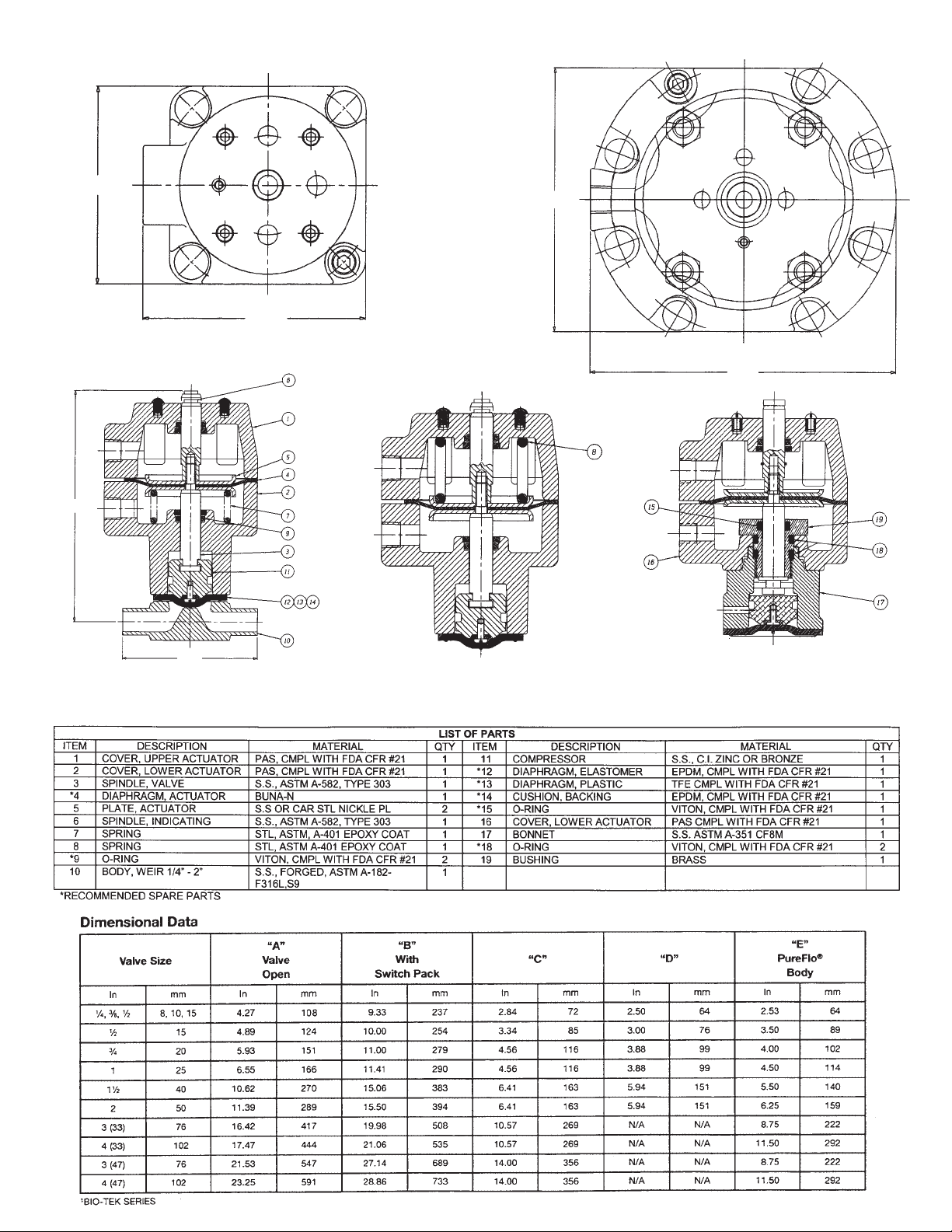
1. Fastener Torques
2. Actuator Travel and Weights
3. Actuator Internal Data
4. O-Ring Sizes
FIGURES:
1. Actuator Drawings
2. Accessories:
- Travel Stops
- Manual Over-Ride (Open) with
Adjustable Opening Stop
- Manual Over-Ride (Close) with
Adjustable Opening Stop
3. Switch Pack 2.0
3A. Switch Pack 2.5
3B. Switch Pack 3.0
4. Positioner
5. Valve Diaphragm Identification
6. PTFE Diaphragm Detail
7. Advantage Assembly & Disassembly Fixture
Pure-Flo
®
Dia-Flo
®
Page 2

2
CAUTION - WELD END VALVES
Weld end valves for schedule 10 and heavier pipe require
actuator removal prior to welding in line. Schedule 5 and
lighter pipe and tubing may be welded with automatic
equipment only without removing the actuator. The valve
must be in the open position and properly purged with an
inert gas. Manual welding requires actuator removal for all
tubing gages and pipe schedules.
1 INSTALLATION
1.1 Dia-Flo
®
diaphragm valves may be installed in any
orientation. For horizontal piping systems to be
drained through the valve, install the valve stem
between 0 and 30 degrees above horizontal. Note:
Pure-Flo
®
valves have either raised hash marks
(castings) or small machined dots (forgings) on
the valve body to indicate the correct drain angle.
Locate these marks at the 12 o’clock position to
achieve the optimum drain angle.
1.2 Prior to pressurization (with the valve
slightly open), tighten the bonnet bolts in
a crisscross pattern in accordance with
Table 1.
Retightening 24 hours after the system reaches operating temperature and pressure is recommended. If
leakage occurs at the body/diaphragm seating area,
immediately depressurize system and tighten bonnet
bolts as noted above. If leakage continues,
diaphragm replacement is required. Follow applicable steps in Section 3.6.1, 3.7.1 or 3.8.1.
1.3 The travel stop (closing stop), if equipped, is factory
set and should not require adjustment at time of
installation. However, if adjustment is required, see
section 4.1.
1.4 Maximum valve operating pressure is 150 PSIG
(10.34 bar). This pressure is applicable up to 100
degrees F (38 degrees C), valves at maximum pressure cannot be used at maximum temperatures.
CAUTION: The actuator size/configuration may limit
the actual operating pressure, consult Engineering
Catalog for actuator sizing. Consult factory or
Engineering Catalog for vacuum operation.
1.5 Air line connections should be made with care as
damage may occur to the standard plastic actuator
covers. Connection size is 1/8” NPT for 1/4” through
2” (DIN 8 - 50) and 1/4” NPT for 3” and 4” (DIN 80 -
100).
1.6 3” and 4” (Series 33 and 47) (DIN 80 and 100)
Advantage
®
actuators must not be lifted by the
air fittings. Prepare an eye bolt with a 0.625“ -18
female thread to attach to the adjusting bushing,
use a hoist to lift with this attachment. (Series 47
only)
1.7 The stainless steel bonnet Advantage
®
Actuator
(1/4”-2”) (DIN 8-50) can have the air inlets positioned in any quadrant. The actuator must be
removed from the valve body and the actuator
diaphragm replacement steps followed. Unthread
the bushing, lift and rotate the lower cover to position the air inlet in the desired quadrant. Press down
on the cover to insure it sits square on the bonnet
and re-assemble the bushing to the proper torque.
Bio-tek: . . . . . . . . . . . . . . . . . . . . . . . . . . .150 in-lb
.50 - 1.0”: . . . . . . . . . . . . . . . . . . . . . . . . .200 in-lb
1.5/2.0”: . . . . . . . . . . . . . . . . . . . . . . . . . .240 in-lb
2 OPERATION & ADJUSTMENT
2.1 The Advantage
®
actuator is a spring-and diaphragm,
or double acting diaphragm, pneumatic actuator.
The actuator model number is located on the ITT
i.d. tag. The model number is a four or five digit
number defining the actuator as follows:
AXYYZ
A = Advantage” Actuator
X = 1 Direct Acting (Spring to Open)
X = 2 Reverse Acting (Spring to Close)
X = 3 Double Acting
YY = Nominal Size. Available sizes
(approximate effective diaphragm area in
square inches): #03, 05, 08, 16, 33, 34, 47, 48.
Z = 6 60 PSI Spring Package
Z = 9 90 PSI Spring Package
Z is only used for Reverse Acting Units
(Spring to Close) sizes 1/4” - 2” (DIN 8 - 50). Note
that for the 3” & 4” actuators A233, A247 represent a 60 PSI Spring Package and A248 represents a
80 PSI Spring Package. A234 represents a 90 PSI
Package.
2.2 Maximum permitted air supply pressure is
90 psig (6.2 bar, 620 kPa).
ACTUATOR PRESSURE RATING
The Advantage actuator has a pressure rating of 90 psig.
However, the actuator will withstand pressures well in excess of
the rated pressure without risk of bursting.
Maintaining operating pressure at or below 90 psig will ensure
optimum life of the operating components, such as the actuator
diaphragm. However, operation at pressures up to 95 psig, for
limited periods of time, will not noticeably affect the life of
these components.
2.3 For operation and adjustment of actuator acces-
sories, see Section 4.0.
2.4 Valve and actuator travel are shown in Table 2.
3 MAINTENANCE
3.1 Periodic Inspection
Periodically inspect condition of external valve parts.
Replace all parts showing excessive wear or corrosion. Leakage from the lower cover or bonnet weep
hole indicates diaphragm rupture. For diaphragm
replacement, see Section 3.6.1, 3.7.1, or 3.8.1. On
sealed bonnet valves, back off the v-notch vent plug
two or three turns. CAUTION: When the process
fluid is hazardous or corrosive, extra precautions
should be taken, the user should employ appropriate safety devices and should be prepared to
control a leak of the process fluid. Fluid weeping
from the plug indicates a diaphragm failure.
Replace diaphragm immediately.
3.2 Pressurized Bonnet
Air pressure from the lower cover or bonnet weep
hole may indicate o-ring failure. Follow applicable
replacement instructions in Section 3.6, 3.7 or 3.8.
Page 3

3
3.3 Diaphragm-Flange Leakage
If valve diaphragm flange area leaks, depressurize
system and open valve slightly, using the wrench
opening device (3” & 4”Series 47 only, DIN 80 & 100
only) or a local bleed type regulator. Tighten bonnet
bolts as described in Section 1.2. If leakage continues, valve diaphragm replacement is required.
3.4 Lubrication
Standard lubricant is Chevron Poly FM2 (FDA
Compliant) for all Pure
-Flo® valves (1/4” through 4”,
DIN 8 - 100) and 1/4” through 2” (DIN 8 - 50)
Dia
-Flo®valves. Sunoco 991EP is standard for 3” or
4” (DIN 80 or 100) Dia
-Flo® valves. The 3” & 4” (DIN
80 & 100) unit requires Never-Seez on the adjusting
bushing/spindle threaded joint and on the travel stop
nuts/adjusting bushing threaded joint. Actuators
should be lubricated in the spindle/o-ring area whenever the actuator is disassembled.
3.5 Advantage
®
Actuator to Valve Body
Mounting Instructions
For double acting (A3YY) and spring-to open (A1YY)
actuators, regulate air pressure in upper cover to
extend the compressor and assemble valve
diaphragm. Correctly position the diaphragm with
bolt holes then back the regulator off until the
diaphragm just rest against the lower cover.
Spring-to close (A2YY) units require air pressure regulated in the lower cover to properly locate the valve
diaphragm.
1/4” through 2” (DIN 8 - 50):
Apply a dab of Dow Corning
®
111, which has FDA
compliance to Title 21 CFR 175.300, to the lead
thread of each lower cover insert. (DO NOT
OVER-LUBRICATE.) No lubricants are permissible
on the diaphragm seal face or body interior/seal
area.
Assemble valve body using the torques shown in Table
1.
3.6 Double Acting
(REMOVE ALL LINE PRESSURE)
3.6.1 Valve Diaphragm Replacement
3.6.1.1 Disconnect air lines. Remove bonnet
bolts, lift actuator assembly from valve
body.
3.6.1.2 Unscrew diaphragm from compressor
by turning counterclockwise.
3.6.1.3 For PTFE assemblies only: Replace backing cushion and PTFE diaphragm.
Note: To engage the threads of the
diaphragm stud invert the PTFE
diaphragm. To invert the diaphragm,
press on the center of the
diaphragm face with thumbs while
holding the edge of the diaphragm
with fingers.
3.6.1.4 Screw new diaphragm into compressor
until hand tight. DO NOT OVERTIGHT-
EN. Then back off until bolt holes in
diaphragm and bonnet flange align.
3.6.1.5 Replace actuator assembly on body
and tighten bonnet bolts with a
wrench, crisscrossing from corner to
corner. See Table 1 for recommended
torques.
3.6.1.6 Travel stop, if equipped, must
be reset
at this time to assure proper closure.
See Section 4.1.
3.6.2 Actuator Diaphragm Replacement:
(1/4” through 2”, DIN 8 - 50)
3.6.2.1 Disconnect air lines. Remove actuator
bolts and remove top cover.
3.6.2.2 Remove indicating spindle, diaphragm
top plate and actuator diaphragm.
3.6.2.3 Install new diaphragm top hat up, use
Blue Loctite #242 on the indicating
spindle.
3.6.2.4 Assemble top cover, using care to keep
the air fitting in line with the lower
cover air fitting.
3.6.2.5 See Table #1 for fastener
torques.
3.6.3 Actuator Diaphragm Replacement:
(3” & 4” Series 47, DIN 80 & 100)
3.6.3.1 Disconnect air lines. It is best to
remove the bonnet bolts, lift actuator
assembly from the valve body and
move the unit to a bench. Remove
clear plastic cap, travel stop nuts,
roller-bearing/races, actuator bolts and
nuts. Remove top cover.
3.6.3.2 Remove adjusting bushing, spindle
nut, diaphragm top plate and actuator
diaphragm.
3.6.3.3 Install new diaphragm, top hat up.
Reassembly is the reverse of the above,
use Blue Loctite #242 on the spindle
nut. Be sure to set the adjusting bushing at the correct position 4.06”
(10.31 cm) from top of the spindle nut
to bottom of adjusting bushing), see
Figure 1. See Table 1 for fastener
torques.
(3” & 4” Series 33, DIN 80 & 100)
3.6.3.4 Disconnect air lines. It is best to
remove the bonnet bolts, lift actuator
assembly from the valve body and
move the unit to a bench. Remove
actuator bolts and remove top cover.
3.6.3.5 Remove extension spindle, both nuts,
diaphragm top plate and actuator
diaphragm.
3.6.3.6
Install new diaphragm, top hat up. Be
sure the diaphragm is positioned so
the diaphragm bolt holes line up with
Page 4

4
the cover bolt holes with no stretching
of the diaphragm. The compressor
extends 0.72” from the bonnet face in
this relaxed position, reference p. 10
for a view of the compressor position.
Re-assembly is the reverse of the
above, use Blue Loctite #242 on the
spindle nut. See Table 1 for fastener
torques.
3.6.4 Spindle O-Ring Replacement
(All Sizes)
3.6.4.1 Disconnect air lines, remove actuator
assembly from valve body and dismantle actuator following instructions
above for removing actuator
diaphragm.
3.6.4.2 Withdraw valve diaphragm, compressor and spindle assembly from the
bonnet.
3.6.4.3 Remove old o-rings, taking care not to
damage machined surfaces. Lubricate
new o-rings per Section 3.4 and install
in grooves. Reassemble reversing the
above instructions. Care must be used
on the Bio-Tek to align the compressor
T-slot with molded tabs in lower cover.
3.7 Reverse Acting
(REMOVE ALL LINE PRESSURE)
3.7.1 Valve Diaphragm Replacement
3.7.1.1 Load the bottom chamber of the actuator with sufficient air to partially open
valve. This will ease the spring tension
holding the valve diaphragm to the
body weir.
3.7.1.2 Remove the bonnet bolts. Lift actuator
assembly from valve body. Release air
and disconnect air line.
3.7.1.3 Unscrew diaphragm from compressor
by turning counterclockwise.
3.7.1.4 For PTFE assemblies only: Replace backing cushion and PTFE diaphragm.
Note: To engage the threads of the
diaphragm stud invert the PTFE
diaphragm. To invert the diaphragm,
press on the center of the
diaphragm face with thumbs while
holding the edge of the diaphragm
with fingers.
3.7.1.5 Screw new diaphragm into compressor
by turning hand tight. DO NOT OVER-
TIGHTEN. Then back off until bolt
holes in diaphragm and bonnet flange
register.
3.7.1.6 Connect air line to lower air chamber
and load chamber with sufficient air
to move the diaphragm upward until
the backing cushion or elastomer
diaphragm rests against the
Advantage Act. lower cover. Do not
apply excessive air pressure that
results in inversion of the diaphragm.
3.7.1.7 Replace actuator assembly on body,
and tighten bonnet bolts hand tight.
3.7.1.8 Tighten bonnet bolts with a wrench,
crisscrossing from corner to corner.
See Table 1 for recommended
torques.
3.7.1.9 Apply sufficient air pressure to the
lower cover to fully open the valve. If
necessary, retighten bonnet bolts.
3.7.1.10 Travel stop (Closing Stop), if
equipped, must
be reset at this time
to assure proper closure. See Section
4.1.
3.7.2 Actuator Diaphragm or Spring Replacement:
(1/4” through 2”, DIN 8 - 50) If present, the switch package must be removed.
Spring-to-Close actuators contain powerful springs
and should not be disassembled unless properly fixtured.
One fixture exists for 1/2”, 3/4”, and 1” (DIN 15, 20, 25)
sizes, and another one for 1.5” and 2” (DIN 40 and 50)
sizes. No special fixtures are required for the 3” & 4” (DIN
80 & 100) sizes. Consult factory for details, see Figure 7.
3.7.2.1 Remove actuator from the valve body.
Apply air to lower cover to simplify disassembly, then release air.
3.7.2.2 Remove valve diaphragm and plastic
indicator spindle plug (found on the
1/4” through 2” (DIN 8 - 50) spindles),
both unthread by turning counterclockwise.
3.7.2.3 Position actuator centrally in fixture,
locating the compressor over the correct spacer in the fixture lower plate.
3.7.2.4 Drop the stem guide through center of
fixture handwheel and position in actuator indicator spindle #10-24 UNC
tapped hole (former plug location).
3.7.2.5 Turn handwheel clockwise until stop
rests on actuator top cover.
3.7.2.6 Remove all cover to cover
caps, bolts, and washers.
3.7.2.7 Turn handwheel counterclockwise until
spring load is relieved.
3.7.2.8 Remove top cover, lift out spring(s),
unthread indicator spindle, remove top
actuator plate and diaphragm.
3.7.2.9 Replace parts using the following pro-
cedure: Place the correct spacer,
dependent on valve size, over the pin
in the fixture lower plate. The 1 1/2”
Page 5

5
and 2” (DIN 40 & 50) sizes require four
(4) threaded rod guides in the lower
cover prior to assembly. Position the
actuator sub-assembly, including
spring(s) and top cover, over the spacer
(i.e., the compressor rests on the spacer). Drop the stem guide through center of the fixture handwheel, actuator
top cover, and locate in the actuator
indicator. Position the upper actuator
cover so the 1/8” NPT inlets in the
upper and lower covers are in line and
the rod guides slide through the clearance holes. Turn the handwheel clockwise to compress the spring(s) until
the covers almost touch. Remove the
four(4) threaded rod guides. Start the
cover bolts and then continue to compress the spring(s) until the covers
touch. Place remaining washers and
bolts in top cover and tighten bolts to
torques shown in Table 1.
3.7.3 Actuator Diaphragm or Spring Replacement
(3” & 4” Series 47, DIN 80 & 100)
If present, the switch package must be removed.
3.7.3.1
Disconnect air lines. It is best to
remove the bonnet bolts, lift actuator
assembly from the valve body and
move the unit to a bench. Remove
clear plastic cap, travel stop nuts,
roller-bearing and races.
3.7.3.2 Turn adjusting bushing clockwise until
contact is made with spring package,
record the number of turns. Remove
actuator bolts and nuts, lift off top
cover. Unscrew spring package from
valve spindle by turning counterclockwise.
3.7.3.3 Remove spindle nut, diaphragm top
plate and actuator diaphragm.
3.7.3.4 Install new diaphragm, top hat up.
Reassembly is the reverse of the above,
use Blue Loctite #242 on the spindle
nut. If the original spring package is
used, turn the adjusting bushing counterclockwise the number of turns
recorded in 3.7.3.2. only after assembling the top cover and fasteners.
Should replacement of the spring
package be required, simply thread the
new spring package onto the valve
spindle. A gap may exist between the
covers until properly bolted together
using a crisscross pattern. See Table 1
for fastener torques.
(3” & 4” Series 33, DIN 80 & 100)
3.7.3.5 Disconnect air lines. It is best to
remove the bonnet bolts, lift actuator
assembly from the valve body and
move the unit to a bench. Remove
actuator bolts and remove top cover.
3.7.3.6 Unthread adjusting bushing, this
relieves the spring load, until it is free
of the valve spindle. Remove the
adjusting bushing/spring plate subassembly and the springs. Remove
spindle nut, top actuator plate and
actuator diaphragm.
3.7.3.7
Install new diaphragm, top hat up. Be
sure the diaphragm is positioned so
the diaphragm bolt holes line up with
the cover bolt holes with no stretching
of the diaphragm. The compressor
should extend 0.72” from the bonnet
face in this relaxed position, reference
p. 10 for a view of the compressor
position. Re-assembly is the reverse of
the above, use Blue Loctite #242 on
the spindle nut. Thread the adjusting
bushing down until it shoulders. A gap
will exist between the covers until
properly bolted together using a crisscross pattern. Use three long bolts to
pull down the upper cover and pinch
the diaphragm. Tighten the standard
cover bolts, replace the three long
bolts and complete the assembly. See
Table 1 for fastener torques.
3.7.4 Spindle O-Ring Replacement (All sizes)
3.7.4.1 Disconnect air lines. Remove actuator
from valve body and dismantle actuator following instructions above for
removing actuator diaphragm and
springs.
3.7.4.2 Withdraw valve diaphragm, compressor and spindle assembly from the
bonnet.
3.7.4.3 Replace o-rings and reassemble by
reversing the instructions and following the steps for replacing a valve
diaphragm. Care must be used on the
Bio-Tek to align the compressor T-slot
with molded tabs in lower cover.
Lubricate o-rings prior to installation
per Section 3.4.
3.8 Direct Acting
(REMOVE ALL LINE PRESSURE)
3.8.1 Valve Diaphragm Replacement
3.8.1.1 Disconnect air lines. Remove bonnet
bolts, lift actuator assembly from valve
body. Pressurize actuator by applying
air to upper cover, extending compressor and diaphragm.
3.8.1.2 Unscrew diaphragm from compressor
by turning counterclockwise.
3.8.1.3 For PTFE assemblies only: Replace backing cushion and PTFE diaphragm.
Note: To engage the threads of the
diaphragm stud invert the PTFE
diaphragm. To invert the diaphragm,
press on the center of the
Page 6

6
diaphragm face with thumbs while
holding the edge of the diaphragm
with fingers.
3.8.1.4 Screw new diaphragm into compressor
until hand tight. DO NOT OVERTIGHT-
EN. Then back off until bolt holes in
diaphragm and bonnet register.
3.8.1.5 Reduce air pressure until back of
diaphragm is flat against bonnet.
Replace actuator and bonnet assembly
on body, and tighten bonnet bolts
hand tight.
3.8.1.6 Tighten bonnet bolts with a wrench,
crisscrossing from corner to corner. See
Table 1 for recommended torques.
3.8.1.7 Release air and permit the valve to
open. If necessary, retighten bonnet
bolts.
3.8.1.8 Travel stop, if equipped, must
be reset
at this time to assure proper closure.
See Section 4.1.
3.8.2 Actuator Diaphragm or Spring Replacement:
(1/4” through 2”, DIN 8 - 50)
If present, the switch package must be removed.
Spring-to-Open actuators contain powerful
springs and should not be disassembled unless
properly fixtured.
One fixture exists for the 1/2”, 3/4”, and 1“ (DIN 15,
20, 25) sizes, and one for 1 1/2” and 2” (DIN 40
and 50) sizes.
No fixture required for 3” & 4”(DIN 80 & 100).
Consult factory for details, see Figure 7.
3.8.2.1 Remove cover bolts and lift off top
cover.
3.8.2.2 Caution: actuator plates are under
load. Loosen the indicator spindle two
turns before placing centrally in the fixture, locating the compressor over the
correct spacer in the fixture lower
plate. Place the slotted fixture plate
and spacer plate on the actuator top
plate; turn the fixture handwheel
clockwise to remove the load from the
indicator spindle. Remove the spindle
and turn the handwheel counterclockwise until the spring load is relieved.
Use care - the diaphragm may pinch
the spindle thread and restrict spring
extension. Examine the diaphragm
through hole for damage and replace,
if necessary.
3.8.2.3 Place the spring in the lower cover and
set an actuator plate, concave side
down, over the valve spindle. Position
in the fixture over the spacer and place
the slotted fixture plate on the actuator plate. Set the spacer plate on top,
turn the fixture handwheel clockwise
and compress the spring until the actuator plate shoulders on the spindle.
Use care to insure the spindle goes
through the actuator plate center hole.
Slide the actuator diaphragm over the
valve spindle using care to insure the
top hat is in the upper cover. Position
the actuator diaphragm so the bolt
clearance holes line up with threaded inserts in lower cover. Place an
actuator plate, concave side up, over
the valve spindle. Apply Blue Loctite
#242 and thread the indicating spindle
on the valve spindle by hand. Turn the
handwheel counterclockwise to
remove the load and remove the actuator from the fixture. Clamp the slotted plate in a vise and pull so the actuator slips free. Tighten the indicator
spindle with a wrench using care to
insure the actuator diaphragm remains
properly aligned.
3.8.2.4 Position the upper actuator cover so
the 1/8” NPT inlets in the upper and
lower covers are in line.
3.8.3 Actuator Diaphragm or Spring Replacement:
(3” & 4” Series 47, DIN 80 & 100) If present,
switch package must be removed.
3.8.3.1 Disconnect air lines. It is best to
remove the bonnet bolts, lift actuator
assembly from the valve body and
move the unit to a bench.
3.8.3.2 Remove clear plastic cap, travel stop
nuts and roller bearing/races.
3.8.3.3 Remove actuator bolts and nuts, lift off
top cover.
3.8.3.4 Remove adjusting bushing, spindle nut
(under load due to spring force),
diaphragm plates, actuator diaphragm
and spring.
3.8.3.5 Using replacement parts, reverse
instructions for reassembly. Use Blue
Loctite #242 on the spindle nut. Be
sure to set the adjusting bushing at
the correct location (4.06” (10.31 cm)
from top of the spindle nut to bottom
of adjusting bushing), see Figure 1.
(3” & 4” Series 33, DIN 80 & 100)
3.8.3.6 Disconnect air lines. It is best to
remove bonnet bolts, lift actuator
assembly from the valve body and
move the unit to a bench. Remove
actuator bolts an remove top cover.
3.8.3.7 Remove extension spindle, both nuts,
diaphragm top plate, actuator
diaphragm and spring.
3.8.3.8 Reassembly is the reverse of the above,
Page 7

7
use Blue Loctite #242 on the spindle
nut. The diaphragm is to be assembled
top hat up. See Table 1 for fastener
torques.
3.8.4 Spindle O-Ring Replacement (All sizes)
3.8.4.1 Disconnect air lines. Remove actuator
from valve body and dismantle actuator following instructions above for
removing actuator diaphragm and
spring.
3.8.4.2 Withdraw valve diaphragm, compressor and spindle assembly from the
bonnet.
3.8.4.3 Replace o-rings and reassemble by
reversing the instructions and following the steps for replacing a valve
diaphragm. Care must be used on the
Bio-Tek
®
to align the compressor T-slot
with molded tabs in lower cover.
Lubricate o-rings prior to installation
per Section 3.4.
4 ACCESSORIES
4.1 Travel (Closing) Stop Adjustment
This feature is standard on 3” - 4” Series 47 (DIN
80-100) actuators and optional on the 1/4” - 2” (DIN
8-50). It is not available on 3” - 4 “ Series 33 (DIN
80-100).
The purpose of the travel stop is to prevent overloading of the diaphragm, thus prolonging
diaphragm life. Travel stops are factory set and
do not require routine adjustment. However, with
replacement of valve diaphragms, travel stop
adjustment is recommended.
4.1.1 All Operating Modes:
4.1.1.1 Remove switch Package if present.
4.1.1.2 Release air pressure in actuator covers.
4.1.1.3 Remove clear plastic cap.
4.1.1.4 To adjust travel (closing) stop, first
loosen jam nuts and back off one turn.
If double or direct acting, apply
enough pressure in top cover to close
the valve. While preventing the adjusting bushing from rotating, turn lower
nut clockwise until valve leaks. Then
turn lower nut counterclockwise until
valve stops leaking while continuing to
insure the adjusting bushing does not
rotate. Tighten jam nuts together, the
travel stop is now set. Replace plastic
cap.
4.2 Combination Manual Over-ride (Open) and
Adjustable Opening Stop
(Manual Over-ride (Open) not available on 1/4”
through 2”, DIN 8 - 50 or 3” & 4”, DIN 80 - 100
Series 33.)
4.2.1 Operation of Manual Over-ride (Open): (3” &
4” Series 47 only, DIN 80 & 100 only)
4.2.1.1 Remove switch Package if present.
4.2.1.2 Release any air pressure in top cover.
4.2.1.3 Remove clear plastic cap and loosen
jam nuts.
4.2.1.4 Use a wrench to hold the adjusting
bushing from rotating, turn the lowest
jam nut clockwise. This opens the valve
0.056” (1.42 mm) per rotation. Rotate
the nut counterclockwise to return
valve to closed position. Note: Travel
stop adjustment is recommended at
this time. See Section 4.1 to adjust
travel stop.
4.2.1.5 Tighten jam nuts together and assemble plastic cap.
4.2.2 Operation of Adjustable Opening Stop:
(1/4” through 2”, DIN 8 - 50)
4.2.2.1 Remove switch package if present.
4.2.2.2 Using air pressure and bleed type regulator, open valve to desired position.
4.2.2.3 Rotate adjusting bushing counterclockwise until resistance is felt.
4.2.2.4 Opening stop is now set. NOTE: VALVE
CLOSED SWITCH REQUIRES ADJUSTMENT.
4.2.3 Operation of Adjustable Opening Stop:
(3” & 4” Series 47, DIN 80 & 100)
4.2.3.1 Remove switch package if present.
4.2.3.2 Remove clear plastic cap.
4.2.3.3 Using air pressure and bleed type regulator, open valve to desired position.
4.2.3.4 Rotate adjusting bushing counterclockwise until resistance is felt. Count and
record the number of turns.
4.2.3.5 Loosen the two jam nuts and turn the
lower nut clockwise the same number
of turns recorded above. Lock the nuts
together. Note: Travel stop adjust-
ment is recommended at this time.
See Section 4.1 to adjust travel stop.
4.2.3.6 Replace cap.
4.3 Combination Manual Over-ride (Close) and
Adjustable Opening Stop
(Wrench closing not available on 1/4” through
2”, DIN 8 - 50 or 3” & 4”, DIN 80 & 100, Series 33.)
4.3.1 Operation of Manual Over-ride (Close):
(3” & 4” Series 47 (DIN 80 & 100)
Direct & Double only)
Page 8
8
ADVANTAGE®ACTUATOR
FIGURE 1
1/4” - 2”
(DIN 8-50)
3
⁄4”-2”
“D”
“D”
“C”
“TOP VIEW”
1
⁄4”-1⁄2”
“C”
“E”
DOUBLE ACTING
&
SPRING TO OPEN AIR CLOSE
SPRING TO CLOSE AIR TO OPEN LOW PROFILE
“A/B”
Page 9

9
ADVANTAGE®ACTUATOR
3” - 4” (SERIES 47)
(DIN 80-100)
“A/B”
DOUBLE & DIRECT
ACTING
REVERSE ACTING
QUANTITY
REQUIRED,
1 FOR DIR. ACT.
2 FOR DBL ACT.
1
⁄4” NPI
FURNISHED WITH
DIR. ACT. ONLY
1
⁄4” NPI
*
*
*
*
*
*
* RECOMMENDED SPARE PARTS
PLASTIC CAP
(TRANSPARENT)
ROLLER BEARING
& RACES
O-RING
TOP
COVER
SPRING
PLUNGER
TRAVEL
STOP
NUTS
VALVE
SPINDLE
ADJUSTING
BUSHING
THRUST
WASHER
O-RING
TRAVEL, STOP, ADJUSTABLE OPENING
STOP & MANUAL OVER-RIDES
FIGURE 2
3” - 4” (SERIES 47)
(DIN 80-100)
Page 10

10
ADVANTAGE®ACTUATOR
3” - 4” (SERIES 33)
(DIN 80-100)
QTY. REQUIRED,
1 FOR REV. ACT.
REVERSE ACTING
DOUBLE & DIRECT
ACTING
QTY. REQUIRED,
1 FOR DIR. ACT.
2 FOR DBL. ACT.
FURNISHED
WITH DIR.
ACT. ONLY
REVERSE ACTING
ACTUATOR DIAPHRAGM REPLACEMENT
Page 11

11
4.3.1.1 If present, the switch package must be
removed.
4.3.1.2 Release any air pressure in bottom
cover.
4.3.1.3 Remove clear plastic cap.
4.3.1.4 Use a wrench to turn the adjusting
bushing counter clockwise to close the
valve (record the number of turns).
Turn the adjusting bushing clockwise
the same number of turns to return
valve to open position.
4.3.1.5 Tighten Travel Stop nuts and assemble
plastic cap.
5 SWITCH PACK 2.0
(The switch package is not autoclavable,
maximum temperature is 150˚ F 65.5˚C)
(Switches and Positioners cannot be used
together)
Retrofit - The switch package as received from
the factory is pre-set, only minimal adjustment
is required to adapt to the actuator.
5.1 Field Mounting (1/4” through 2”, DIN 8 - 50, 3” &
4”, DIN 80 & 100, Series 33)
5.1.1 Remove the four(4) stainless steel screws on
the actuator top cover. Place the valve in the
open position.
5.1.2 Remove the plastic plug from the indicating
spindle.
5.1.3 Thread the switch indicating spindle into the
valve indicating spindle. Use Blue Loctite #242.
5.1.4 Mount the adapter, insure that both O-Rings
are on the adapter and lubricated with Dow
111. The correct torque is 5 in-lbs (.656 Joules).
5.1.5 Slide the switch sub assembly down over the
adapter, position the conduit entrances in the
location most desirable, (45˚ increments), press
down and tighten the set screw located on the
side of the lower housing to lock the unit in
place. The set screw torque should not exceed
5 in-lbs (.656 Joules).
5.1.6 Holding the lower housing stationary, unscrew
the top switch package cover and wire to the
terminal strip (Reference factory wiring decal).
Verify the switches operate correctly by cycling
the valve, see 5.3 for switch adjusting procedure. Screw the switch package cover on,
insure the O-Ring remains in the groove.
5.2 Field Mounting
(3” and 4” Series 47, DIN 80 and 100)
5.2.1 Remove the clear plastic cap from the actuator.
5.2.2 Thread the switch indicating spindle into the
valve indicating spindle. Use Blue Loctite #242.
5.2.3 Thread on the adapter, insure that the O-Ring
is in place at the base of the adapter.
5.2.4 Slide the switch sub assembly down over the
adapter, position the conduit entrances in the
location most desirable, (45˚ increments), press
down and tighten the set screw located on the
side of the lower housing to lock the unit in
place. The set screw torque should not exceed
5 in-lbs (.656 Joules).
5.2.5 Holding the lower housing stationary unscrew
the top switch package cover and wire to the
terminal strip (Reference factory wiring decal).
Verify the switches operate correctly by cycling
the valve, see 5.3 for switch adjusting procedure. Screw the switch package cover on,
insure the O-Ring remains in the groove.
5.3 Setting Switches
(Switches are identified with decal)
5.3.1 Remove top switch package cover.
5.3.2 Place valve in full open position.
5.3.3 Connect test device to terminal strip on connections identified for SW (open) switch. The
switch type, inductive proximity versus dry contact mechanical, determines the type of test
device required. Contact switches use a traditional volt meter with resistance capability to
verify continuity, inductive proximity switches
cannot use this method. Proximity switches
require an inductive proximity tester, such as
Pepperl+Fuch’s model #1-1305, which supplies
the proper load and supply voltage to the
switch. Inductive proximity switches must be
energized with the correct load and supply
voltage to sense the target.
WARNING: DO NOT SHORT THE INDUCTIVE
PROXIMITY SWITCH BY DIRECTLY CONNECTING A POWER SUPPLY, IRREPARABLE AND
IMMEDIATE DAMAGE CAN OCCUR TO THE
SWITCH.
5.3.4 Loosen the two (2) screws on the open switch
slightly.
5.3.5 Use the adjusting screw accessible from the top
to move the switch up or down the bracket to
the optimum position. (Two turns past the trigger location is recommended.)
5.3.6 Tighten the two (2) screws on the switch.
5.3.7 Place the valve in the full closed position.
5.3.8 Repeat the above steps for the SW (closed)
switch.
5.3.9 Replace the top switch package cover.
6 SWITCH PACK 2.5
(The switch package is not autoclavable,
maximum temperature is 150˚F, 65.5˚C)
(Switches and Positioners cannot be used
together)
Page 12

12
SWITCH PACK 2, SP2.0
FIGURE 3
“A”
“A”
5.29
BIO-TEK
THRU 02.00
9.75
DETAIL “B”
(03.000 & 04.000 SERIES 47)
SEE DETAIL “B”
SECTION “A-A”
DETAIL “B”
(BIO-TEK - 01.000)
NOTE:
1. RECOMMENDED SPARE PARTS ARE MARKED WITH AN
ASTERISK (*) ON THE LIST OF PARTS.
2. ▲- USED ON BIO-TEK - 01.000
+ - USED ON BIO-TEK - 02.000
- USED ON 1.500 & 02.000
- USED ON 03.000 & 04.000
∆ 3. SWITCHES
PROX P&F #NJ3-V3-Z
PROX P&F #NJ3-V3-N
PROX P&F #NJ3-V3-E
PROX P&F #NJ3-V3-E2
MECH #X97173-V3L (SIL CONT)
MECH #X97174-V3L (GOLD CONT)
● 4. USED ONLY WITH PROXIMITY SWITCHES.
5. USED ONLY WITH MECHANICAL SWITCHES
➜
WIRING LABELS (ITEM 31)
Page 13

13
Retrofit - The switch package as received from
the factory is pre-set, only minimal adjustment
is required to adapt to the actuator.
6.1 Field Mounting (1/4” through 1”, DIN 8 - 25)
6.1.1 Remove the four(4) stainless steel screws on
the actuator top cover. Place the valve in the
open position.
6.1.2 Remove the plastic plug from the indicating
spindle.
6.1.3 Mount the adapter, insure that both 0-Rings
are on the adapter and lubricated with Dow
111. The correct torque is 5 in-lbs (.565 Joules).
6.1.4 Place the washer on the adapter. Thread the
switch indicating spindle (item 12) into the
actuator spindle. Use Blue Loctite #242.
6.1.5 Slide the switch sub assembly down over the
adapter, position the conduit entrances in the
location most desirable, (45˚ increments), press
down and tighten the set screw located on the
side of the lower housing to lock the unit in
place. The set screw torque should not exceed
5 in-lbs (.565 Joules).
6.1.6 Attach target assembly (item 9) to switch indicating spindle (item 12) using shoulder screw
with Belleville washers in place. Use Blue
Loctite #242. Run field wires and conduit to
terminal strip. (Reference factory wiring tag.)
Verify the switches operate correctly by cycling
the valve, see 6.2 for switch adjusting procedure. Screw the switch package cover on,
insure the O-Ring remains in the groove.
6.2 Setting Switches
(Switches are identified with decal)
6.2.1 Remove top switch package cover.
6.2.2 Place valve in full open position.
6.2.3 Connect test device to terminal strip on connections identified for open switch. The switch
type, inductive proximity versus dry contact
mechanical, determines the type of test device
required. Contact switches use a traditional
volt meter with resistance capability to verify
continuity, inductive proximity switches cannot
use this method. Proximity switches require an
inductive proximity tester, such as
Pepperl+Fuch’s model #1 - 1350, which supplies the proper load and supply voltage to the
switch. Inductive proximity switches must be
energized with the correct load and supply
voltage to sense the target.
WARNING: DO NOT SHORT THE INDUCTIVE
PROXIMITY SWITCH BY DIRECTLY CONNECTING A POWER SUPPLY, IRREPARABLE AND
IMMEDIATE DAMAGE CAN OCCUR TO THE
SWITCH.
6.2.4 Use the switch actuator (item 7) accessible
from the top to set the optimum position. (Two
turns past the trigger location is recommended.)
6.2.5 Place the valve in the full closed position.
6.2.6 Replace the top switch package cover.
7 SWITCH PACK 3.0
(The switch package is not autoclavable,
maximum switch temperature is 140˚F,
60˚C.) (Switches and Positioners cannot be
used together.)
Retrofit - The switch package as received from
the factory on valve assemblies is pre-set, only
minimal adjustment is required to adapt to the
actuator.
7.1 Field Mounting (1/4” through 2”, DN 8 - 50)
7.1.1 Remove the four (4) stainless steel screws on
the actuator top cover. Place the valve in the
open position.
7.1.2 Remove the plastic plug from the indicating
spindle.
7.1.3 Insure all O-Rings are on the adapter and lubricated with Dow 111. Slip the switch indicating
spindle, #10-24 UNC threads first, through the
adapter until the threads are exposed. Apply
Blue Loctite #242 to the threads, thread the
switch spindle into the actuator spindle until it
shoulders.
7.1.4 Attach the adapter to the upper cover. The correct torque is 5 in-lbs (.565 Joules).
7.1.5 Thread the appropriate switch actuator(s) on
the spindle.
7.1.6 Position the closed switch actuator approximately 0.14” (4 turns) from end of threads and
position the open switch actuator approximately 0.25” (7 turns) below the top of the spindle,
do not tighten the set screw.
7.1.7 Remove the switch package top cover, slide the
sub assembly down over the adapter using
care not to damage the switch internals
(specifically the mechanical switch levers).
Position the conduit entrance in the location
most desirable, press down and tighten the set
screw located on the side of the lower housing
to lock the unit in place. Note that the plastic
adapter has two molded counterbores.
Locating the set screw in one of these holes
provides maximum resistance to conduit rotation. The set screw torque should not exceed 5
in-lbs. (.565 Joules).
7.1.8 Run field wires and conduit to the terminal
strips. Verify the switches operate correctly by
cycling the valve. See 7.2 for switch adjusting
procedure. Screw the switch package top cover
on.
7.2 Setting Switches
Page 14

14
SWITCH PACK 2.5, SP2.5
FIGURE 3A
ASSEMBLE BELLEVILLE WASHERS IN
SERIES AS SHOWN
(3.70) DIA
(3.32)
SEE DETAIL “B”
SECTION “A-A”
DETAIL “B”
“A”
“A”
NOTE:
1. RECOMMENDED SPARE PARTS ARE MARKED WITH AN
ASTERISK (*) ON THE LIST OF PARTS.
● 2. SWITCHES
PROX P&F #NJ3-V3-Z
PROX P&F #NJ3-V3-N
PROX P&F #NJ3-V3-E
PROX P&F #NJ3-V3-E2
MECHANICAL X96324-UM (SIL CONT)
MECHANICAL X96325-UM (GOLD CONT)
▲ 3. USED ONLY WITH MECHANICAL SWITCHES.
WIRING DIAGRAM CARDS (ITEM 30)
Page 15

15
7.2.1 Remove top switch package cover.
7.2.2 Place valve in full open position.
7.2.3 Connect test device to terminal strip for open
switch. The switch type, inductive proximity
versus dry contact mechanical, determines the
type of test device required. Contact switches
use a traditional volt meter with resistance
capability to verify continuity, inductive proximity switches cannot use this method. Proximity
switches require an inductive proximity tester,
such as Pepperl+Fuch’s model #1-1350, which
supplies the proper load and supply voltage to
the switch. Inductive proximity switches must
be energized with the correct load and supply
voltage to sense the target.
WARNING: DO NOT SHORT THE INDUCTIVE
PROXIMITY SWITCH BY DIRECTLY CONNECTING A POWER SUPPLY, IRREPARABLE AND
IMMEDIATE DAMAGE CAN OCCUR TO THE
SWITCH.
7.2.4 Bio-1.50” (Two Switch Actuators)
7.2.4.1 Verify the switch package locking set
screw is tight.
7.2.4.2 Verify the circuit board is firmly seated.
7.2.4.3 For mechanical switches only, press on
the top of the circuit board to move it
toward the switch actuator. Thread the
switch actuator two (2) turns past the
initial switch indication.
7.2.4.4 Lock in place with the set screw on
switch actuator.
7.2.5 2.0” (One switch actuator)
7.2.5.1 Do not set the switch in the open
position, set the switch in closed position. Follow 7.2.4 with the valve in full
closed position. Confirm open switch
functions in full open position only
after setting in closed position.
7.2.6 Place the valve in the full closed position and
connect the appropriate test device to the terminal strip for valve CLOSE switch. Repeat section 7.2.4-7.2.5 for the valve CLOSED switch.
Note on SP 3.0 units, the closed switch actuator must never hit the adapter in the closed
position with body attached.
8 POSITIONERS
(Switches and Positioners cannot be used
together)
(A special adjusting bushing is required for 3”
& 4“ (DIN 80 & 100) Actuators with positioners)
8.1 Scope: Top-mounted positioners listed below
8.1.1 Moore 73N12F (A100 & A300 Series Actuators)
(Direct Acting Positioner, Top Loading)
8.1.2 Moore 73NB (A200 Series Actuators) (Direct
Acting Positioner, Bottom Loading)
8.1.3 Moore 73NFR (A100 & A300 Series Actuators)
(Reverse Acting Positioner, Top Loading)
8.2 Supply and Instrument Pressures
8.2.1 Instrument input pressure range - as specified:
3-15 psi (.21 - 1.03 bar) (standard), 3-9 psi
(.21-.62 bar), 6-30 psi (.41-2.07 bar) and others
are optional.
8.2.2 Supply pressure: 3 psi (.21 bar) above required
actuator pressure to a maximum of 90 psi (6.2
bar). A filtered air supply is recommended.
8.2.3 Caution: Pressure in excess of 90 psi (6.2
bar) to any connection may cause damage.
8.3 Description
The positioner is designed to operate a valve actuator to maintain the valve in a position determined by
the control instrument. The above positioners are
direct acting - with an increase in instrument pressure, the pressure to the actuator (positioner output)
will increase or reverse acting - with an increase in
instrument pressure, the pressure to the actuator
(positioner output) will decrease. On a bottom load-
ing positioner (73NB), output is connected to the
actuator lower chamber via an external tube.
Therefore, the valve will open as instrument pressure
increases. The 73NB is the only unit which can have
an O-ring in the actuator upper cover
. All others
operate on the concept that air feeds the upper
cover by flowing down the indicating shaft and into
the cover. (This means that a field retrofit for
Double and Direct units must have the O-ring
removed and a special slotted adjusting bushing.)
Double Acting (A300 Series) require the lower actuator cover to be pre-loaded, use a bleed off type regulator with gauge. (This is standard when ITT supplies
the assembly.)
8.4 Installation
The only task is to connect the supply and instrument air. All connections are 1/4” NPT. Use 1/4” O.D.
tubing for the instrument connection, either 1/4” or
3/8” O.D. (6.35 or 9.52 mm) tubing for the supply
connection. Blow out all piping before connections
are made to prevent the possibility of dirt or chips
entering the positioner. Use pipe sealant sparingly,
and then only on the male threads. A non-hardening
sealant is strongly recommended. Connect the positioner to a source of clean, dry oil-free air. A filtered
and regulated air source is recommended.
Note: Synthetic compressor lubricants in the air
stream at the instrument may cause the positioner to fail.
Note that a cushion loading regulator is furnished
with 3300 series actuators and a tee in the supply
connection is routed to this regulator, so an extra
hookup is not required. The cushion loading regulator should be set at the minimum pressure required
to open the valve wide open. Typically, this is 10 psi
(0.69 bar) or less.
Page 16

16
SWITCH PACK 3.0, SP3.0
FIGURE 3B
(ADAPTER)
ADVANTAGE
ACTUATOR
BIO-TEK - 1.00”
(INDICATING
SPINDLE)
ASSEMBLE WITH LOCTITE
SEALANT #242 (BLUE)
ADVANTAGE
ACTUATOR
(INDICATING
SPINDLE)
ASSEMBLE WITH LOCTITE
SEALANT #242 (BLUE)
1.50” & 2.00”
Page 17

17
8.5 Adjustment
The only adjustment that can be made on the positioner is a zero adjustment. The zero adjusting screw
is located under the positioner’s top cover. To make
this adjustment, set the instrument air pressure to
the midpoint of its span, and turn the zero adjustment until the valve is at the mid-point of its stroke.
Refer to Table #2 for stroke information. Recheck the
setting accuracy by changing instrument air pressure
to the maximum/minimum point to obtain full
open/closed valve position.
In some cases, valve shut-off or opening may be
required at a specific instrument pressure. To zero
the positioner at this point, set the instrument signal
at the specific pressure and turn the zero adjustment
screw until the valve reaches the required position. A
slight change of the instrument pressure should start
to move the valve. The valve stroke for a given span
may also be suppressed or shifted to the desired
range by means of the zero adjusting screw.
8.6 Maintenance
A clean, oil and moisture free air supply will reduce
maintenance problems. The supply air filter should
be blown down on a routine basis. The filter element
should be examined periodically and replaced if necessary. No lubrication is required on the valve positioner. The system should be shut down or the valve
isolated from the system before service or removal of
the positioner is accomplished.
For additional maintenance activities, refer to the
Manufacturer’s service manual.
Page 18

18
POSITIONER
FIGURE 4
3
⁄4” - 4”
(DIN 20-100)
Page 19

19
FIGURE 5
VALVE DIAPHRAGM IDENTIFICATION
ELASTOMER - 1 PIECE, MADE OF RUBBER, WITH
MOLDED IN STUD. (SEE TABS)
Page 20

120
13.56
20
Page 21

DWG. ITEM 13 7.9 14 10 12 13
03 #110 #110 #110, #112 N/A #117 #116 #152
05 #112 #112 #112, #114 N/A #117 #116 #152
08 #112 #112 #112, #114 N/A #117 #116 #152
16 #114 #114 #114, #118 N/A #117 #116 #152
*33 #208 #214 N/A N/A #117 #116 #152
*47 #212 #214 N/A #128 #128 #116 #152
ACT SIZE ACTUATOR ACTUATOR LOW ACTUATOR SP2 SP2 SP2
AXYY UPPER LOWER PROFILE CAP BASE ADAPTER/COVER UPPER COVER/
COVER COVER BUSHING • • • LOWER COVER
1) *FDA COMPLIANT BUNA N MATERIAL
2) STANDARD MATERIAL, UNLESS NOTED, IS FDA COMPLIANT VITON
21
TABLE 4
O RING CHART
ADVANTAGE ACTUATOR AND SWITCH PACKAGE, SP2
Page 22

22
NOTES
Page 23

23
NOTES
Page 24

Pure-Flo Solutions Group
For more information, please contact:
Engineered Valves Headquarters
33 Centerville Road, P.O. Box 6164
Lancaster, PA 17603-2064 USA
or call: (800) 366-1111
(717) 509-2200
Fax: (717) 509-2336
Website: www.engvalves.com
E-mail: engvalves_custserv@fluids.ittind.com
©2001 ITT Industries
Pure-Flo Solutions Group
Headquarters
33 Centerville Road
Lancaster, PA 17603
Phone 800-366-1111
Phone (717) 509-2200
Fax (717) 509-2336
Pure-Flo California
Formerly ITT Sherotec
725 East Cochran Street, Unit E
Simi Valley, CA 93065
Phone 800-926-8884
Phone (805) 520-7200
Fax (805) 520-7205
Pure-Flo Sweden
Formerly A.G. Johansons Metallfabrik
Box 26 Vasterasvagen 6
S-730 40 Kolbäck
Phone +46-220-403-20
Fax +46-220-405-23
Pure-Flo UK
Formerly Sinton Group
Richards Street
Kirkham, Lancashire
PR4 2HU, England
Phone +44-1772-682696
Fax +44-1772-686006
OFFICE LOCATIONS
 Loading...