

INSTRUCTION MANUAL
MODEL: BT-100
SINGLE BUCK BODY AND SLEEVER
SERIAL NUMBER :
PURCHASED DATE:
ITSUMI SEISAKUSHO CO., LTD. SAITAMA JAPAN
TITLE: INSTRUCTION MANUAL
DWG.NO. TOR-060404
REV. 04/20//2006

CONTENTS
● SAFETY INSTUCTIONS A-1~ A-4
●INSTALLATION OF THE MACHINE B-1~ B-4
●PERIODIC CHECK C-1~C-2
●FUNCTIONS OF SECTIONS D-1~D-5
●HOW TO OPERATE E-1~E-6
●MAINTENANCE AND SERVICE F-1~F-12
●SPECIFICATIONS OF THE MACHINE G-1~ G-6
●TROUBLE SHOOTING AND COUNTERMEASURES H-1~ H-4

SAFETY INSTRUCTIONS
PREFACE
This Instruction Manual states the way how to use the Machine correctly, the cares to be taken in using the
Machine, and so on. In order for you to fully make use of the performance of the Machine and use it safely,
please read through this Instruction Manual to its end before using the Machine. After having read it, please
do not forget to keep this Instruction Manual so that you can utilize it right away in case you need it.
INDICATIONS OF RISKS
In order for you to use the Machine safely and in the right way and to prevent any injury from occurring to the
Machine attendants and any other persons as well as any property, this Instruction Manual has the indications of
risks. Kinds of such indications and their meanings are as follows:
WARNING
CAUTION
A WARNING is used to indicate instructions necessary to
cause any injury to human body and life if ignore this
indication and/or incorrect operation.
A CAUTION is used to indicate instructions necessary
to cause any injury to human body and life if ignore this
indication and/or incorrect operation.
A NOTE is used to indicate proper operating methods
and inspection points if ignore this indication to cause
any injury to human body and/or physical damage.
NOTE
A-1
SAFETY INSTRUCTIONS
WARNING
WARNING
DON’T BE TRAPPED
When the machine begins to operate, do not move your hand,
face, or other parts of the body within the moving space of the
iron and/or the machine.
●You may get suppressed, bruised, or burned.
BE CAREFUL WITH HIGH-TEMPERATURE PARTS
Steam pipes, steam hoses, and iron get extremely hot. Never
touch these parts with your hand.
●This could cause burns.
Nobody is allowed to operate or service this machine other than
those who first read and understand this instruction manual.
WARNING
WARNING
WARNING
TURN THE POWER OFF BEFORE INSPECTION
When replacing covers, doing inspection/maintenance work, or
cleaning the unit, be sure to turn the power switch off so the
machine would not operate while you work.
●This could cause an accident and/or an electric shock.
SECURE A GROUND CONTACT
After setting up the machine or moving it, be sure to secure a
ground connection.
●Electric leakage and charges of static electricity could cause an
electric shock or natural fire.
A-2
WARNING
WARNING
STOP IMMEDIATELY IF THE MACHINE
DAMAGES A SHIRT
While using the unit properly and correctly, if any damage is
found on the shirt being pressed, stop the operation immediately
and find the cause.
●This minimizes the damage.
DO NOT REORGANIZE OF THE MACHINE
We are surely recommended to prohibit reorganize of the
machines specification changes and removal of the warning
label etc.
●May cause of unexpected accident.
WARNING
WARNING
CAUTION
PAY ATTENTION TO THE INSTALLATION
LOCATION OF THE MACHINE
Make sure to install the machine in a room where there is no
influence from weather and to keep it free from water and steam.
●Improper installation may cause damage to the machine and an
electric shock due to a short circuit.
INSPECT STEAM LEAKS
Please inspect loose steam piping and steam leaks carefully.
●If steam leaks remain untouched, steam may be discharged and
cause burns.
CLEAN AIR-FILTER AND LINTO COVER
Prior to start work please clean and get rid of the drain filter for
the air and be accumulated in the oil mist separator as drain and
the oil are daily. Lint covers for the hot air blowing fan motor is
also.
● It is cause to be inferior the quality of the air parts and drying
condition if accumulated drain and the dust.
A-3
CAUTION
CAUTION
EXECUTE THE REGULAR CHECK
We are surely recommended execute the regular inspection more
than once per year for confirm the performance and activates
safely of the machine. Also please execute to replace the
consumption articles when limit the life time has come.
CONSUMPTION ARTICLES ARE MUST BE USE GENUINE
PARTS
We surely recommends to use our genuine parts when replace
each kind of pad or cover.
●In case to use except our genuine replace parts, it could not
well enough perform to activation than original piece.
A-4
INSTALLATION OF THE MACHINE
INSTALLATION OF THE MACHINE
Place the Machine on a proper level surface. It is a great impact on the action and life time of
the Machine whether it is ensured to be leveled.
For a place where the Machine is positioned, choose a secure floor that can withstand it’s
weight.
Secure space around the Machine so that the maintenance work will be done without
difficulty (More than 80cm is necessary).
For set up, more than 2 anchor bolts are needed to prevent fall.
Secure the space to see the name plate for confirm the type and serial numbers for repair the
machine etc.
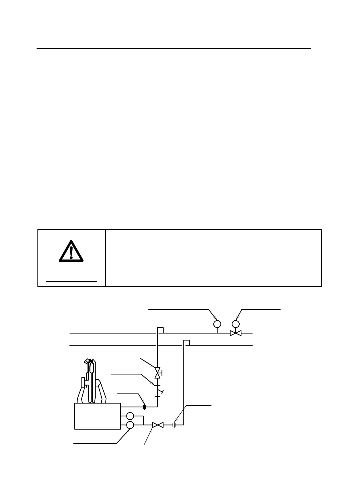
STEAM PIPING WORK
For use in steam piping, use steel pipes for pressure of 1/2in. or greater.
Make the whole piping slightly down to the ground so it’s not to cause of any stagnant drain
water.
Regulate the pressure of steam entering to the Machine between 0.5 and 0.65MPa.
Install valve and strainer to the steam inlet side of the Machine.
Install the trap where steam outlet side of the machine.
WARNING
Reduce pressure up to 0.65MPa or lower which steam is
supplied to the machine.
●Suspect to damage steam iron and presser vessel.
STEAM INLET
STEAM OUTLET
VALVE
STRINER
UNION
PRESSURE GA UGE
UNION
REGULATOR
STEAM TRAP
CHECK VALVE
B-1
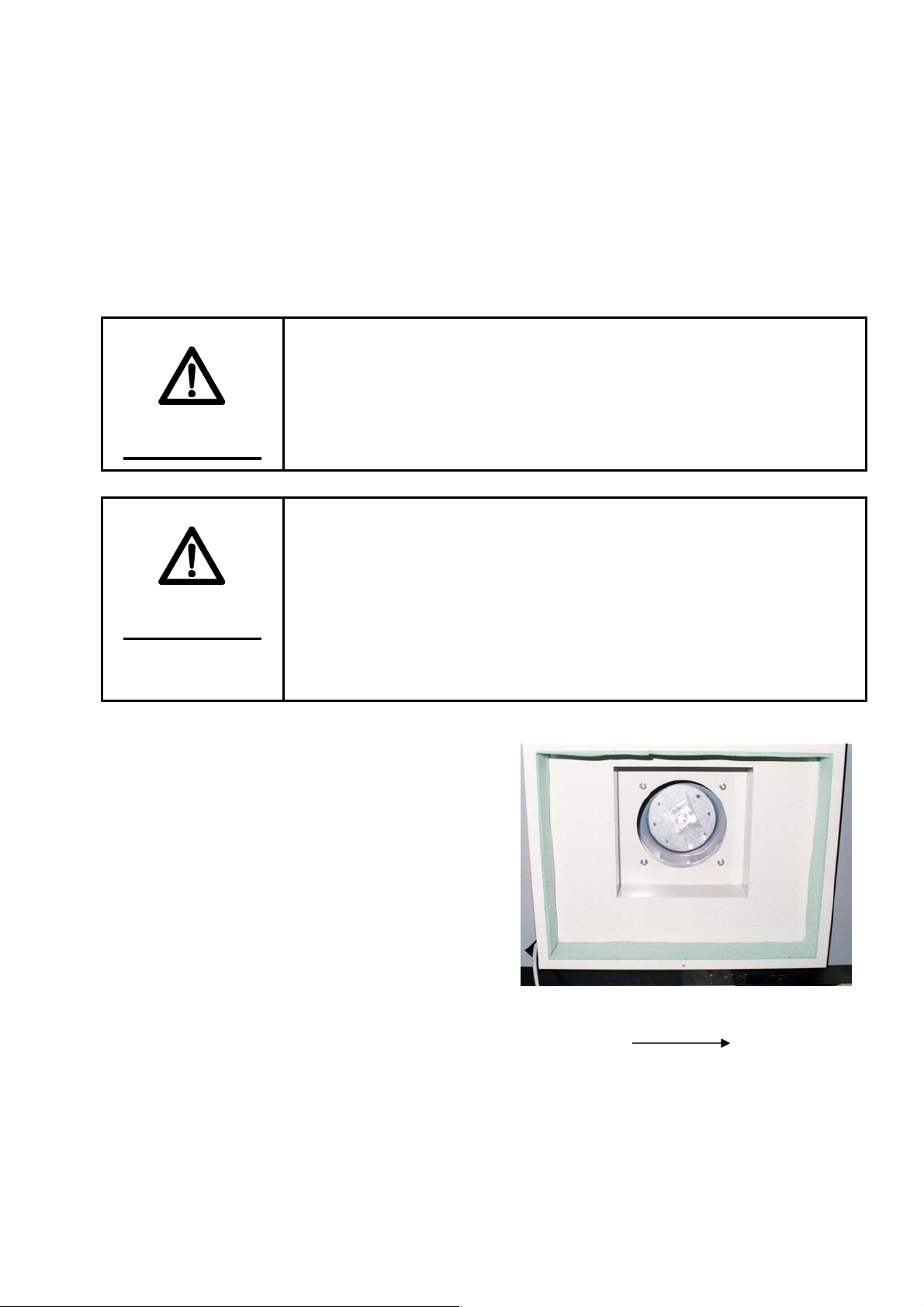
ELECTRIC WORK
Power source is 3-phase, 200V, 30amps, 50/ 60Hz. It has 4 lines, one of which is ground wire
(green co lour).
When fitting a suitable plug to the AC line cord, it is essential that it contains an
earth/ground contact and that must be connected. Earth wire into the ground without fail.
Keep electric wiring part at least 15cm from steam pipe due to escape the heat.
Make sure that the turning direction of blower motor is same direction of below drawing that
the turning direction is anti counter clockwise from the front view.
Install the short circuit breaker where the side of power source
of the machine due to prevent the trouble and electric shock.
●Recommend short circuit breaker: 30A
●Regular electric current: 30mA
●Power source: 3-phase, 200-220V, 60Hz
WARNING
ENFORCE THE CONTACT EARTH WIRE INTO THE
GROUND
In case of the earth wire has not been adopt, can not have the
place to escape the abnormal electricity and/or static electricity
and it may cause of the risk of electric shock. Also, the high risk
WARNING
for the incorrect activation of the machine if affect by the
thunderbolt struck. And it may cause if the serious fire explosion
accident.
Direction of Rotation
B-2
AIR PLUMBING
This machine will be needed to work that the power is more than 1 horse power (0.75 Kw)
compressor. Please use it well enough power even if the power is more than 1 horse power if
it’s to operate complex of the machine at the same time.
Please use the inner size of the pipe is bigger than 8mm for the air plumbing in case if it’s use
under 8mm it may result of reduce the pressure momentary and influence the function of the
machine incorrectly and finish condition as well.
Standard pressure of the main air regulator will be 0.5MPa if reducing the pressure during
the service it may cause of the shortage of the air supply so check the following cause.
・Capacity shortage of the compressor
・Shortage of the hose.
・Operating the complex of the machine at the same time.
・Leak the air and shut the air valve.
Set the valve as for the inlet side to able to shut the air when periodic maintenance.
We are surely recommended to have space approximately plumbing distance 10m between
compressor and the machine. Pressed air has been cool and easy to remove the moisture by
the filter.
CAUTION
CONTROL THE COMPRESSOR
Moisture and oil and impurities are makes the air filter being
short life and affects bad influence of the air parts so keep the
compressor in good condition for use long.
B-3
TRIAL OPERATION OF THE MACHINE
After install the machine, upon confirm connect for the steam, electricity and the air activate trial
operation.
1. Open the machine
・ Get rid of the vinyl cover and lapping paper.
・ Get rid of the rectangular timber where fixed the back iron for the body press and left arm.
・ Remove the foot switch to the easy operation at the front part of the machine.
2. SET THE COVER FOR LEFT EDGE OF THE MACHINE.
3. RELEASE THE LOCK CONCERNING THE AIR.
・ Supply the air for the machine and make sure
Status of the body press iron is closed by
・
manual o
valve for body press. For release the body
press iron, remove the manual switch of the
electro-magnetic valve for press from
condition of 「ON」to 「OFF」. Normally it
is available to work 「OFF」 status.
4. R
ETURN TO THE ORIGIN POINT.
・ eep press stop button more than 2 seconds,
K
each device will move to the origin po
pen the dummy
5. O
Re
・ move the lapping paper covered on the dummy.
・ Remove rectangu
6. Connect the power supply
C
・ onnect the breaker for the factory.
・ Check the indication on th
7. Steam Supply
・
Open the steam valve for supply the steam for the machine.
・ Check the stea
8. TRIAL OPERATION OF THE MACHINE.
・
According to the operating process later on, activate the machines function.
・ It is necessary to activate 4 or 5 times trial pre
peration of the electro-magnetic
int as regulated turn.
lar timber for fix the collar cramp.
e machine when you turn on the power switch of the machine.
m leakage from the steam circuit.
that the pressure level should be 0.5MPa.
4KB310
ss w/o shirt when you finish actual shirt.
B-4
PERIODIC CHECK
DAILY PRE-USE CHECK
Do not use the machine if all the safety devices and stop
buttons are does not work normally. Check this matters
everyday before use this machine.
WARNING
Air filter for moisture and oil contents can automatically discharge such impurities with drain
when drains are accumulates. Check if impurities are discharged normally, and in case drains
are stagnant, and then please dispose of it by hand.
Check if all the pressure decompression valves are at specified pressures.
Main Regulator 0.50MPa
Tuck Slide Start 0.09Mpa
Tuck Slide Back 0.12Mpa
Dummy Slide Regulator 0.30Mpa
Remove the dust gathered on the inlet filter of the hot air blower for an arm.
Check if the cover of the dummy has not torn around the body and the tuck and if the pad has
not worn out if can not use please replace it as our genuine replace parts.
Check if air does not leak at the interconnected of the air hoses.
Check if steam does not leak at the interconnected of the steam as steam hose and/or each
plumbing parts.
Check if the air pressure is stable during operating the machine. If air pressure does not stay
appropriate level during the work check air filter and decompression valve.
PERIODIC CHECK A YEAR
Please execute periodically replace the filter elements as for following method.
NAME ELEMENTS REPLACEMENT TERM
Drain filter E-60D 2 years passes or pressure under 0.1MPa
Filter F4000-KIT 2 years passes or pressure under 0.1MPa
Oil mist separator MANTLE-ASSY 1 year passes or pressure under 0.1MPa
Please apply the grease for the dummy slide rail as well as apply the slide rail for tuck press
device for smooth movement.
Check if leakage from the packing of interconnected circuit of hot air blowing as for the
sleeves and air bag if you found any leakage, replace the packing for use long time.
C-1

Efficiency of the filter for the air will be decrease by time passed
by so that the volume of the passes the air will be decreased
naturally. We are surely recommended to replace it as regulated
condition.
NOTE
C-2

FUNCTIONS OF THE SECTIONS
13 7 71 9 10 11 12 5 8
P RE SS TI ME R
TUCK OFF
ST OP
CO U NT ER
O N
START ST A RT
OFF
PRO
TIMING TIMER
AIR HEAT TUCK
2 3 4 6
OPERATION PANEL
①POWER SWITCH
When you turn the switch lever to “ON", that the Machine becomes ready to be operated. Times
you select are indicated in the timer display window.
②AIR (Timer for airbag start activate)
You can set the timing for air coming in the airbag (placed at the sides of the Dummy). This
timer counts at the time when trunk pressing starts, and when the set time passes by, hot air
comes in the sides of the Dummy.
REMARK:
-The longer set the time, the later timing for the hot air blowing comes.
→If the front placket curves, then set the time longer.
-The shorter set the time, the earlier timing for the hot air blowing comes.
→If wrinkles come out at the sides, then set the time shorter.
D-1

③HEAT (Timer for hot-air come)
You can set the timing for hot air comes into the sleeves. When you press cuffs setting button
that the timer starts counts and passes the previously sat the time hot-air blowing comes into
the sleeves.
REMARK:
-The longer set the time, the later timing for the hot air blowing comes.
→If the tuck spread becomes shorter, then set the time longer.
-The shorter set the time, the earlier timing for the hot air blowing comes.
→If you can see the wrinkles on the sleeve, then set the time shorter.
④TUCK (Timer for press the tuck)
You can set the timing for pressing the tucks. This timer starts concurrently with the HEAT
Timer.
REMARK:
-SET THE TIME LONGER, TIMING FOR PRESSING THE TUCKS BECOMES LATER.
→IF YOU CAN SEE THE WRINKLES ON THE SLEEVE, THEN SET THE TIME LONGER.
- SET THE TIME SHORTER, TIMING FOR PRESSING THE TUCKS EARLIER.
→ IF THE TUCKS OPEN AND BECAME SHORT, THEN SET THE TIME SHORTER.
⑤PRESS TIMER (Timer for press )
You can set 3 different pressing times from the Course 1 to 3. Choose any of them depending on
the material and moisture condition of a shirt.
⑥TUCK OFF (The Key)
When you press this button that the lamp turns on and the tuck pressing stops if you push it
once again, the lamp light turns off and the tuck press will start finishing works.
⑦START (Button)
After you have finished to setting the collar and vacuum, press these 2 buttons that the Dummy
moves to the right, making it ready for the trunk to be pressed and for the cuffs to be set. Keep
on pushing the buttons until the iron touches the Dummy.
⑧STOP (Button)
When you press this button return to the status of the press released condition and stops other
activations. If you would like to start again, keep on push this button more than 3 seconds.
Each of the devices will be returned to the origin point.
In case if you could touch the safety device where located
tuck and truck trunk iron, activate the same function as press
the stop button.
NOTE
D-2

➉ to ⑪ TIME ALTERATION BUTTON
Please refer “SET THE TIMER” paragraph.
⑫ TIME INDICATION WINDOW
Indicate remaining time if you are in the finishing process, without this process will indicate
the setting time. If the timer became out of order it will be shown “ERROR MARK” in the
window.
⑬ COUNTER WINDOW
Count the finished pieces.
HOW TO SET THE TIMER
1. SELECT THE COURSE
Push the timer button which you would like to change the
course and the lamp turns on that you have selected. Indicate
current setting time in the time indication window number 12
twelve.
2. PROGRAMMING MODE BUTTON
Push this programming button number 9 nine approximately
1.5 seconds and time indication numbers turns into blinking
signal so that you can rewriting your favorable time.
3. SET THE TIME.
For an adjust your favor time push these marked ▲(Plus)
number ➉ ten ▼(Minus) number ⑪ eleven buttons. If you
would like to change the time widely keep press these button to
adjust your favorable time quickly.
4. ENTRY THE MEMORIZE
Push programming button number ⑨ nine about 1.5
seconds again memorize the renewal time together with stop
blinking signal and the high tone P sound.
PRO
PRO
PRO
1
2
3
設定時間
D-3

EXTERNAL FEATURES OF THE MACHINE
6 65 5
8
9
10
2
3
7
4
1
①CONTROL BOX
This contains electric control-related parts, such as sequencer and relay (thermal breaker).
②FOOT SWITCH
Pedaling this switch activates the collar fixer, where in turn operates vacuum.
③AIR FILTER
This serves as the inlet of hot air coming in the sleeves and forms a filter (net) collecting dust.
④AIR PRESSURE-REGULATING VALVE OF THE TUCK SLIDE
This regulates the expansion force of the sleeves.
⑤CUFFS CRAMP SWITCH
Push this button close the cuffs cramp and push it again it will be opened.
⑥START BUTTON (GREEN)
After sat both right and left cuffs press these two buttons enter the process of trunk finish work.
Keep the buttons on till the tuck press touches the shirt.
D-4

⑦STOP BUTTON (RED)
Push this button effects to return the status of released the press and stop the other function.
When you re-start to work the machine press this button more than three seconds each device
will be returned to the origin point.
⑧SAFETY GUARD
Safety guard device is installed where at in front of the tuck press iron and side of trunk iron if
this device start to work it is the same function of press the stop button. When you re-start to
work the machine keep stop button on more than three seconds then each device will be
returned to the origin point.
⑨OPERATEING PANEL
This panel has installed each setting and dummy movement button.
➉REGULATION BOX (ELECTRIC MOTOR CIRCUIT)
Installed magnet relay for the motor.
D-5

HOW TO OPERATE
FINISH PROCESS (Long Sleeves)
1. FASTEN THE SHIRT
Put the shirt to the dummy from left side back
around the dummy.
2. SET THE SHOULDER
Set the shirt to the dummy to make equal to the
seam line of the shirt.
3. SET THE COLLAR
Fix the collar by using the foot switch to make
equal space between collar and the collar block
then activates the vacuum when you press the
collar. When you release the collar press, step
on the foot press switch once again
E-1

4. SET THE BACK OF THE SHIRT
Pull down the bottom of the shirt lightly to not
appear any of slack wrinkles.
5. SET THE FRONT BOTTOM PART
Spread the bottom of a shirt for appropriate
condition to the dummy.
6. SET THE FRONT BOTTOM PART
Spread the bottom of a shirt for appropriate
condition to the dummy.
7. FRONT STAND
Set the front stand become straight from your
view. If you can find the curve on the shirt,
make it straight for fine finish. The angle for
the front stand both right or left makes narrow
as for the bigger shirt.
E-2

8. SMOOTH OUT OF SMALL WRINKLE
It may appear little wrinkle where the part of
pocket. shoulder, and the side so prior to finish
apply appropriate stroke or pull the shirt.
9. MOVE THE DUMMY
When you finished process number 8, press
START buttons at the same time by both hand
that the dummy will move to the right side.
* Keep the buttons on till the iron is completely
pressed.
10. TRUNK PRESS
The dummy was stopped at the extremely right
end and activates trunk press at the same time
and left arm comes to the front.
11. SET THE CUFF
Through the cuff on the pedestal for finish an
arm and the cuff place on the right position
without appear any wrinkles for the cuff and
tuck. Fixed the cuff by press the cuff cramp
switch. You can set the cuff either right or left
first.
E-3

12. SET THE CUFF
Insert the cuff tip part approximately 2 to 3 cm
and pay attention to insert cuff deeply it may
cause to remain impressed part.
13. START FINISH WORK
Press the START buttons by the each hand at the
same time then start finish work. Time passes by
for previously set the timer that automatically
release and the dummy return to left.
ep the button on till the iron must be
* Ke
pressed completely.
4. END OF FINISH WORK
1
Remove the shirt from the
easy to remove if you handle as sample picture.
dummy (Trunk). It is
E-4

SHORT-SLEEVED SHIRTS FINISH WORK
1. to 10. FASTEN SHORT-SLEEVED SHIRT
Put the short-sleeve shirt onto the trunk as same
way from the numbers 1 to 9 of the long-sleeved
shirts.
11. T-SHIRT CRAMP DEVICE
Pull out the cramp in front of you.
12. SET THE T-SHIRT
Insert the sleeve to the cramp device for the
short-sleeve shirt and set it by press the button.
E-5

13. START FINISH WORK
Press the both of START button at the same
time and start finish work.
14. EXPAND THE SLEEVE
Pulling the sleeve with hot air blowing and
complete the arm part. As for the T-shirts finish
process does not activates the press device for
sleeve.
15. END OF THE FINISH WORK
Remove the T-shirt from the dummy (Trunk) as
the same way of long sleeves shirt.
E-6

MAINTENANCE AND SERVICE
When the maintain for this machine, evacuate steam and air,
disconnect electricity, and wait until all steam-heated
sections have been cooled.
●High risk for unexpected accident and electric shock may
WARNING
happen.
AIR FILTER REGULATOR
REGULATOR
DUMMY MOVING
OIL MIST SEPARATOR
FILTER
DRAIN FILTER
REGULATO R
MAIN
DRAIN FILTER (DF600-04-A)
Eliminate the moisture and filtration water will be discharged automatically. (Auto drain)
AIR-FILTER (F4000-15-F)
For the filter which percolation ratio 5μm affects remove the dust and foreign substance
mainly. Dust and foreign substance through the filter will be discharged automatically with
water. (Auto drain)
OIL MIST SEPARATOR (M400-15-F1)
For the filter which percolation ratio 0.01μm affects remove the oil mainly. Oiled substance
through the filter will be discharged automatically. (Auto drain)
F-1

DECOMPRESS VALVE (For main air pressure : R4000-15)
Adjust the air pressure entering the entire part of the machine.
Standard air pressure: 0.5MPa
Decompress valve (For the dummy movement: R3000-10)
Adjust the air pressure for the movement of the dummy.
Standard air pressure: 0.3MPa
REMOVAL OF THE DRAIN WATER
Percolation drain water will be accumulated into the definite volume cup or pressure in the bowl
became under the level 0.02MPa drain water will be discharged automatically. (Auto drain)
As for collect these drain water, connect the urethane tube (inner size 6mm) to the outlet
connector and put the receptacle plate. And also you can turn the drain knob to anti clockwise,
discharge the drain water by the manual.
REPLACE THE FILTER ELEMENTS
The filter elements apply to push the cup turns to approximately 30 degrees and set the marked
place then you can remove to turn the elements by hand directly. Replace time for the elements
are referring as below table.
FILTER ELEMENTS
NAME SERIAL NUMBERS ELEMENTS REPLACE TERM
Drain filter DF600-04-A E-60D 2 years or pressure under 0.1MPa
Filter F4000-15-F F4000-KIT 2 years or pressure under 0.1MPa
Oil mist separator M4000-15-F1 M type 1 year or pressure under 0.1MPa
F-2

ADJUST THE AIR PRESSURE
This machine has 4 decompression valves for the main,
dummy movement, enter and return of the tuck slide part.
Decompression valve for the air role keep the supplying
pressure to definite level and the way of the pressure
adjustment is pull up the knob lightly and turn it properly
and check the pressure level by the pressure gauge.
Turn the knob to clock wise effects high pressure and turn
anti clock wise effects lower pressure from the view of the
knob side. After set the appropriate level that the knob
return to the origin point and lock it accordingly by hand
press.
*Confirm the pressure level by activate the machine after
sat the pressure if the pressure has changed re-adjust it.
STANDARD PRESSURE OF THE AIR DECOMPRESSION VALVE
NAME STANDARD PRESSURE EXPLAIN THE ACTIVATION
Main 0.5MPa Adjust pressure where supply to the machine
Move the dummy 0.3MPa Adjust pressure for dummy move cylinder
Tuck slide ENTER 0.05MPa Adjust pressure for pull the sleeve
Tuck slide RETURN 0.1MPa Adjust pressure for return the device for pull
the sleeve.
PRESSUER GAUGE
KNOB
F-3

REPLACE THE TRUNK PAD AND COVER
Due to have activates the machine many times that the part of the trunk and air bag, pad and the
cover for the tuck press part will be exhausted. We are surely recommends to replace that the
parts periodically.
When you replace the pad and cover we are surely recommends
to use our genuine parts.
●If you set different parts it may happen to raise cause of worse
finish condition and the life time of the machine shorter.
NOTE
STRUCTURE OF THE TRUNK PAD, COVER AND AIR BAG
① Cover
② Uniron pad
③ Silicone pad
④ Air bag
⑤ Spring for hang air bag
⑥ Bottom fix spring
⑦ Stop plate of the back
⑧ Nut
⑨ Dummy
⑩ Collar fixer
10
6
5
1
4
2
3
8
5
9
7
F-4

REMOVE THE PAD AND COVER
1. Loose two anchor bolts where fixed collar fixer and remove it from the dummy.
2. Loose the fixed hose nut where connecting the cylinder of collar fixer and remove air hose.
3. Remove the strings where in the arm cover.
4. Remove the spring for bottom fixed.
5. Remove the rope where at the blowing inlet of shoulder air bag.
6. Remove the cover from the dummy.
7. Pull out the bottom bar which previously removed the cover.
8. Remove the union pad from the dummy.
FITTING THE PAD AND COVER
1. Fit new union pad on the dummy and to be dressed equal space for both right and left and does
not appear the slacks.
2. Insert the bottom bar for the new cover.
3. The cover will fit and dressed on the dummy.
4. Tight the strings at blowing inlet for the shoulder air bag.
5. Suspend the bottom fix spring to the cover.
6. Remove the strings of an arm cover.
7. Connect the air hose to the collar fix cylinder.
8. Set the collar fixer to the dummy.
REMOVE THE AIR BAG
1. Remove the suspend spring where located both upside and lower part of the air bag.
2. Remove the setting nut where located at both upside and lower part of the air bag.
3. Remove the air bag together with fix plate of the bag from the dummy.
4. Pull out the bag fix plate from the air bag.
FITTING THE AIR BAG
1. Insert the bag fix plate for the new air bag.
2. Fitting the air bag and fix plate of the bag on the dummy
3. Fixed the air bag for using the nut.
4. Set the suspend spring where upside and lower part of the air bag.
F-5

STRUCTURE OF THE TUCK
AND PAD COVER
① Tuck cover
② Tuck uniron pad
③ Tuck silicone pad (Upper)
④ Tuck silicone pad (Lower)
⑤ Tuck frame
4
1 23
5
REPLACEMENT OF THE TUCK AND PAD COVER
1. Release string of the tuck cover to remove the cover.
2. Remove the tuck uniron pad.
3. Peel away silicone pad by striper.
4. Apply silicone adhesive to the tuck frame.
5. Set tuck uniron pad.
6. Set tucks cover.
Set the silicone pad to the tuck frame. Drying time for
silicone adhesive will be necessary approximately 24 hours.
CAUTION
F-6

CIRCUIT PROTECTOR (CP31F-M/2)
Due to happen to had over load capacitance caused by the damage of the parts or short circuit for
the interconnected electrical wiring part shut down the interconnected circuit and protect the
regulation circuit of the electric regulation box if does not showing consequences the operation
even turn on the power supply switch check the circuit protector and in case the switch turn off
inspect the cause of it and when you cleared the reason then turn the lever on in due course.
Installation place: Control box
POWER SUPPLY (S8PS-0524D)
This is a parts for transforming the electrical regulation from outer AC200V to DC24 which
supplying the electricity to the machine. When the machine activating normally where the green
LED lamp will be turned on.
Installation place: Control box.
SEQUENCER (CPM1A-40CDT-D-V1)
This is a parts activates each mechanical function as for electro magnetic valve and relay
according to previously programmed when enter the signal of the press button and sensor.
Confirming the machine to enter the signal of the inlet and outlet that this parts will be shown by
the LED signal and to this sign it is available to know the status of the machine and cause of
abnormal activation.
Installation place: Control box.
POWER SUPPLY
CIRCIT
PROTECTOR
SEQUENCER
CONTROL BOX
F-7

THERMAL RELAY
Thermal relay is located at regulate box for electric motor
where the back part of the machine.
When applying over load capacitance to the electric motor
raise the thermal and shut down the circuit when you recover
circuit be cleared the cause of it and push that resetting
button.
Installation place: Control box for electric motor.
RESET BUTTON
SPEED CONTROL
This is a parts for regulate the movement speed of the cylinder as for adjust air volume where
discharge from the cylinder and you can select from both two types which set the connector of the
cylinder hose and set discharging platform for the electro magnetic valve.
HOW TO ADJUST THE SPEED
① Loose the lock nut.
② Turn the adjustment knob and the volume will
about a quarter a time, this adjustment knob
effects to became slowly if apply tightly and became
faster when you open it vice varsa.
③ Confirm the speed to activate the machine.
④ Repeat that work and if you can not see any of the
trouble then fix the lock nut.
REGULA TING THUMB SCREW
LOCKNUT
REGULATING THUMB SCREW
LOCKNUT
F-8

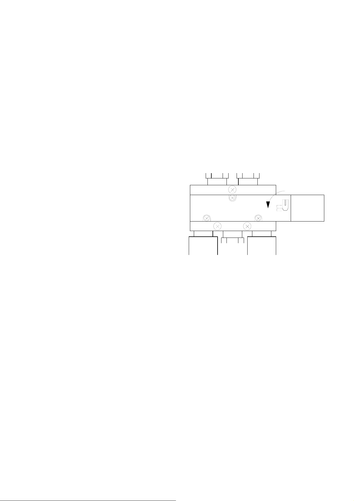
ELECTRO MAGNETIC VALVE
The electro magnetic valve turn the air direction by electric signal and affects the cylinder works
expand and shrink. For this machine built in nine ranges manifold type and also single setting
type electro magnetic valve.
9 (NINE) RANGES MANIFOLD TYPE
①Signal code
Wiring to the regulate box.
②Plug connector
Able to alternate electrical wiring easily as touch
at once whether replace the electro magnetic
valve and in case of unfastening pick it out with
the fingers.
③Indicator lamp
Turn the lamp on when through the electricity.
④Manual control button (Orange co lour)
Press the button affects same movements as turn
on the electricity to the electro magnetic valve.
When press this button use the tip part must be
thin object like ball point pen.
⑤Setting screw
This is the screw for fix the electro magnetic
valve. Remove this screw when replace it.
⑥Quick release joint
When you remove the hose, pull out the hose
with pushing the ring.
⑦Silencer
Installed at the air discharging outlet and reduce
the exhaust sound.
6 3
1
4 57
12 23
PLACE THE ELECTRO MAGNETIC VALVE
OUT LET NUMBERS ROLE OF THE ELECTRO MAGNETIC VALVE
1102 Air bag cut valve
1005 Tuck slide
1004 Tuck apply pressure
1006-1007 Arm circling front and back
1100 Cuffs cramp right
1101 Cuffs cramp left
1106 Fix the dummy
1107 Collar fixer
1104 Sleeve expand
F-9

FOR TRUNK PRESSURIZATION
①Signal code
To be wired to the regulation box.
②Plug connector plus indicator lamp.
When turn on electricity the lamp will be on
and when you remove pull out the center
screw.
③Manual control knob
Regular: Turn to the 0 (zero)
Manual: Turn to the 1 (one)
④Silencer with speed control
Control air exhaust sounds as well as regulate
the volume of the discharging air and then
adjust the iron speed of the open and shut.
E1: Close the iron
E2: Open the iron
⑤Setting screw
Pull out this screw when the time for replace
the electro magnetic valve and it is available
to replace valve part w/o manifold to remain.
4 5
1
2
3
FOR REMOVE THE DUMMY
①Signal code
It is wiring to
magnetic v
solenoid so existing signal code for two places.
②
Manual control button (green)
When y
sam
e movements as turn on the electricity.
Setting screw
③
Remove this screw when the time to replac
electro magnetic valve and it is available to
replace part o
remain.
Silencer
③
Installed
the regulation box. This electro
alve has been work double
ou push this button you can see the
e
f the valve w/o manifold to
at the air discharging place to reduce exhaust sounds.
1
2
2
4
3
1
F-10

AIR CYLINDER
The actions of each section of the
machine are brought by the air cylinder.
Understand the outline of the air
cylinder and make use of it for
countermeasures in case any trouble
occurs.
Names of each part
① Cylinder tube
② Piston rod
③ Air cushion valve
④ Contact less switch
⑤ Speed control
⑥ Knuckle joint
Air cushion
Outline
This absorbs the shock arising when the
cylinder stops by reducing air flow.
Regulation
Loosen the locknut and turn the
regulating valve.
Turn to the right: Effect becomes stronger.
Turn to the left: Effect becomes weaker.
6 5 512
3 34 4
LOCKNUT
REGULATING THUMB SCREW
CAUTION
If effect is made too strong or moisture accumulates in the air
cushion hole, the piston will not go up to the ending points, thus
causes the machine to stop.
F-11

Contact less switches
Outline
When the piston comes under the contact less switch, it switches on and the lamp lights on. The
machine confirms the position of the cylinder in this way.
“The contact less switch does not work."
This happens in almost all cases when the position where the piston stops has changed. Check the
cause of it and correct it.
FIXING SCR EW
INDICATOR LAMP
CONTACTLES S SWITCH
RED(+)
BLACK(-)
Do not change the position of the contact less switch
thoughtlessly.
NOTE
F-12

SPECIFICATIONS OF THE MACHINE
MAIN ITEMS
Name: Single Buck Body and Sleever
Model: BT-100
Air supply pressure: 0.5 - 0. 7 MPa
Max Steam consumption pressure: 0.7MPa
Power source: 3 phase 200 V
Electricity consumption: 2.5 Kw (50Hz) / 2.7Kw (60Hz)
Net weight: 650 Kg
AIR ADJUSTMENT
Main regulator: 0.5 MPa
Tuck slide enter: 0.04 MPa
Tuck slide return: 0.1 MPa
Moving the Dummy: 0.3 MPa
Recommend Compressor capacity: 2 Horse power
PLUMBING DIMENSION
Steam inlet: 3/4 inches
Steam outlet: 1/2 inches
Air inlet: 1/2 inches
TIMER SETTING
Air blowing: 1.0 second
Hot air blowing: 2.0 seconds
Tuck pressing: 2.5 seconds
Course 1: 13 seconds
Course 2: 15 seconds
Course 3: 20 seconds
REMARK
1 MPa ≒10.2kg f/cm2
1 kg f/cm2 ≒0.98 MPa
G-1

TOP ASSEMBLY DRAWING
650
540
STEAM INLET 1/2"
1670
ANCHOR
4
1
φ
455
1082
897
1613
248
AIR INLET 1/2"
2127
50
1211
750
938
STEAM OUTLET 1/2"
115 1710 302
G‑2

WIRING DIAGRAM
0V
TRUNK OPEN
TRUNK CLOSE
DUMMY RIGHT
DUMMY LEFT
00
01
02
+24
P C 0V
COM
00
COM
01
COM
03
10CH
02
03
COM
START BUTTON
CUFF RIGHT BUTTON
CUFF LEFT BUTTON
PRESS BUTTON
STOP BUTTON
ARM BACKWARD
ARM FORWARD
04
05
06
07
08
0CH1CH
04
05
COM
09
06
07
COM
AIR BUG TIMER
10
11
00
01
00
TIME
SS‑2
COLOR CLAMP SWICH
HOT AIR TIMER
01
02
MS1
TH1
TUCK OFF
TUCK PRESS TIMER
FINISH TIMER
02
03
11CH
03
COM
MS2
COUNTER
TH2
DUMMY LOCK UP
DUMMY LOCK DOWN
04
05
06
07
04
05
06
07
HOT AIR (SLEEVE)
TIMER START
DUMMY RIGHT
DUMMY LEFT
TUCK PRESS
ARM FORWARD
TUCK SLIDE
24V
HOT AIR
BLOWER
MOR1
W1
V1
U1
INVERTER
FWD CM
BLOWER
AIR BUG
MOR2
W2
V2
U2
TH1
MS1
BLOWER
VACUUM
MOR3
U3
V3
W3
TH2
MS2
CUFF RIGHT
ARM BACKWARD
CUFF LEFT
P
L
VACUUM
AIR BUG
AIR BUG VALVE
COM
N
N
TRUNK PRESS
SHOULDER EXPANSION
BUMMY LOCK
START
AIR BUG
TUCK PRESS
HEAT
FINISH
102
101
100
1001
1234578
103
11
12
+24V
‑24V
COLLAR CLAMP
COM
TUCK OFF
104
TIMER
T1
AC200V
R S T
E
CP
U
G‑3

WIRING DIAGRAM
SHOULDER EX R
TUCK SLIDE R
TUCK SLIDE L
TUCK PRESS R
46
45 5
9
TUCK PRESS L
10
ARM TURNS
CUFF CLAMP R
CUFF CLAMP L
COLLAR CLAMP
27
49
50
SHOULDER EX L
DUMMY LOCK
28
29
33
33
545 49
16 1146 44 48
46
14
41
10
42
42 42
TRUNK PRESS
3030
4342
DUMMY MOVES
434215
8 22
2 3 4
1
G‑4

TROUBLE SHOOTING
A
Symptom Cause Treatment
Power does not come to
switch and does not
indicate operation panel.
Collar cannot be set. Some section is not return to
Fixing of the collar is not
strong enough.
Electricity is not supplying
Activating circuit breaker
its starting point or not
apply the command.
Foot switch is damaged.
Some abnormal input is in.
Electro magnetic valve is
damaged.
Fixing rubber has worn.
ir is leaking from the
cylinder.
Air hose is broken or leaking
Check the power source cord and your
factory's breaker.
Check the cause of short circuit, etc and
reset the circuit protector.
Check the sensor for releasing the iron,
left side of dummy, or left arm in the back.
Check if the signal of the foot switch
comes in the sequencer.
Buttons for the emergency stop, cuffs,
press, etc. usually receives no input.
Check the voltage and actions of the
electro magnetic valve for collar fixer.
Regulate it by tightening the regulating
bolt at the cylinder head.
If there is no room for regulation, replace
the fixing rubber.
Replace packing of the cylinder.
After checked around hose and amend it.
Vacuum does not work.
Weak vacuum work. Lost vacuum hose quality
Foot switch is broken.
The thermal relay is
working due to over load
capacitance.
and/or gap the hole.
H-1
Replace foot switch. Vacuum starts at
the same time with the collar fixing. In
case the foot switch is broken, the collar
is not fixed either.
This is caused by over load capacitance
in the vacuum motor and activating
thermal relay.. Remove the cause of over
load capacitance on the motor and reset
the thermal relay.
Replace the vacuum hose.

TROUBLE SHOOTING
Symptom Cause Treatment
Dummy does not move to the
right.
Does not come left arm in
front.
Do not press the trunk.
To see the devices are not
returned to regulate position or do
not enter command even
returned at regulate position.
Damaged electro magnetic valve.
Damaged start button.
Dummy does not move right end.
Damaged electro magnetic valve.
Dummy does not move right end.
Damaged electro magnetic valve.
Check the sensor for release iron,
left side of dummy and back of left
arm.
Check electro magnetic valve for
dummy move or replace in case.
Check start button or replace in case
Check the sensor for dummy move
device and right side of dummy.
Check electro magnetic valve for
arm revolving or replace it in case.
Check the sensor for dummy move
device and right side of dummy.
Check electro magnetic valve for
trunk press or replace it in case.
Do not set cuffs
Do not start finish timer. Damaged button for start sleeve
Do not pull sleeve. Appropriate air pressure level
Damaged button for cuffs press.
Damaged electro magnetic valve.
Do not enter the command for
shut the trunk iron.
Damaged electro magnetic valve
Replace cuffs press button.
Check electro magnetic valve for
cuff or replace it in case.
Check sleeve button and replace it
in case.
Check the sensor for shut the
trunk iron.
Adjust the pressure level of electro
decompression valve for tuck slide
in tuck slide return.
Check electro magnetic valve for
tuck slide or replace it in case.
H-2

TROUBLE SHOOTING
Symptom Cause Treatment
Do not come hot air. Proper setting of the timer for
hot air blowing.
Activating thermal relay due to
over load capacitance of hot air
motor.
Do not press tuck Place the switch to TUCK OFF.
Timer for press tuck to be later
activation is too late.
Damaged electro magnetic valve.
Do not end finish work.
Finishing timing is too long.
Damaged the timer.
Reset the timer to a suitable time.
Remove cause of over load
capacitance of motor and reset
thermal relay.
Push TUCK PRESS button again to
make the status of turn off the lamp.
Set appropriate the timer.
Check electro magnetic valve for
tuck press or replace it in case.
Adjust and set the timer appropriate
time for finish.
Check signal of end of finish sign
must be entered to sequencer when
timer has over.
Worse finish condition of
side.
Affect to see the curve at
front stand.
Swelling air bag is weak.
Swelling time of air bag is late.
Swelling the air bag is too fast. Adjust appropriate timing of the
Check if air leakage between blower
motor for air bag and air bag.
Adjust the timer to swell air bug
properly.
timer set longer in this case.
H-3

TROUBLE SHOOTING
Symptom Cause Treatment
Raising the wrinkles in
front and back of the
trunk.
Raising small wrinkles
where at the sleeve.
Tuck for the sleeve will
open.
Raising stain. Stained the pad cover.
Worn out the part of the cover and
cover.
Poor drying condition due to hot
air blowing is not well enough.
Timing of hot air come into the
sleeve is earlier.
Drying condition is not well
enough.
Replace the pad and cover.
Check root valve of steam and trap
and/or check filter for finish timer or
clean it in case.
Adjust the timer to appropriate time
for hot air blowing in this case set
the timer to long.
Replace the pad cover.
Make the timer to long for finishing
or dehydrate to strong.
H-4
 Loading...