

Page 1
HEAT PUMP WATER HEATER
Installation & Instruction Manual
Page 2

1.Introduction for product
2.Operation principles
3.Performance data
4.Installation
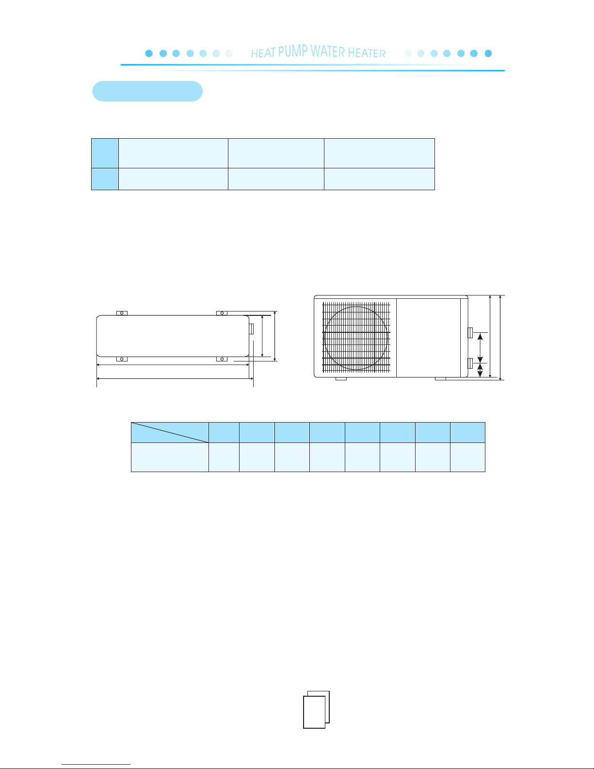
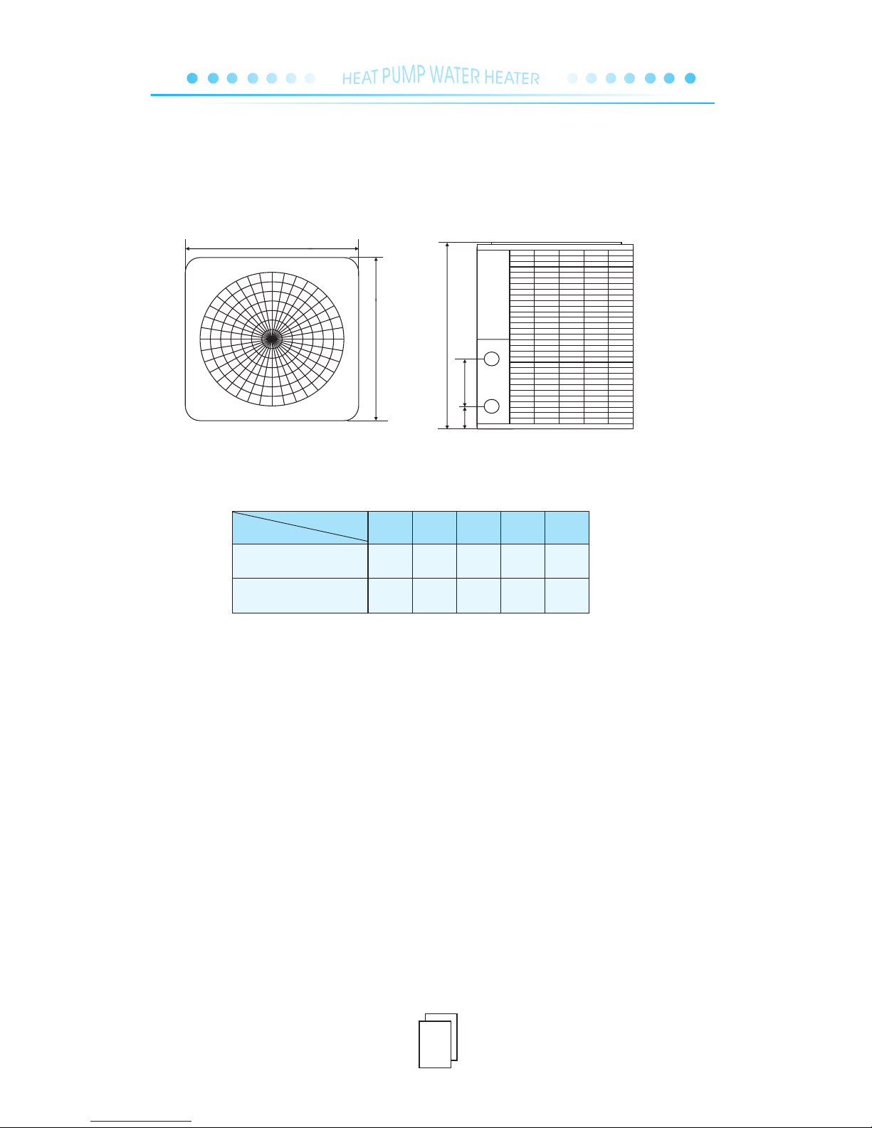
4.1. Dimensions
4.2. Free space for installation
4.3. About water tank
4.4. Pipeline connections
4.5. Pre-operation
4.6. Normal operation
5.Operation
5.1. Controller illustration
5.2. Selecting mode
5.3. Checking current parameters
5.4. Parameter overview (Table 1)
5.5. Parameter overview (Table 2)
5.6. Setting parameter
5.7. Setting time
5.8. Setting TIMER ON/OFF
5.9. Cancellation of TIMER ON/OFF
6. Failure code overview
7. Wiring diagram
8. Maintenance
1
2
3
4
5
6
6
7
7
7
8
8
9
9
10
11
12
12
12
12
13-14
15-16
17
Page 3
Page 4
1
1.PRODUCTION INTRODUCTION
Page 5
2
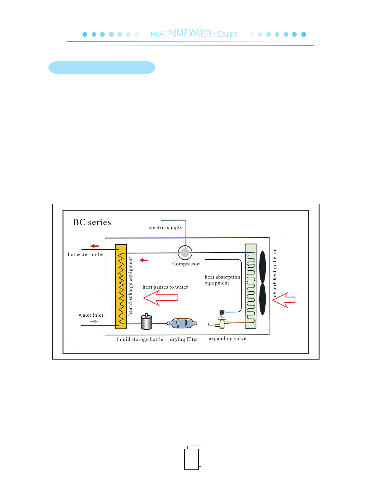
The compressor absorbs from the evaporator the low-temperature and low-pressure gas refrigerant,
compress t h e refrigerant i n t o high-temperature and h i g h -pressure gas, a n d the gas w i l l enter the
co ndense r to exc hange ene rgy with wat er, dur ing which, the ga s is con densed in the cond enser int o
low-temperature liquid to discharge a lot of heat, which is absorbed by water to increase its temperature.
Then, when the high-pressure and low-temperature liquid throttles and reduces its pressure in expansion
va lve, due to the fan in t he evapor ator, i t ab sorbs ene rgy from the sur roundi ng a ir t o ev apora te i nto
low-pressure gas and then is pumped into the compressor to be compressed, thus entering another cycle
to produce hot water.
2.OPERATION PRINCIPLES
Page 6
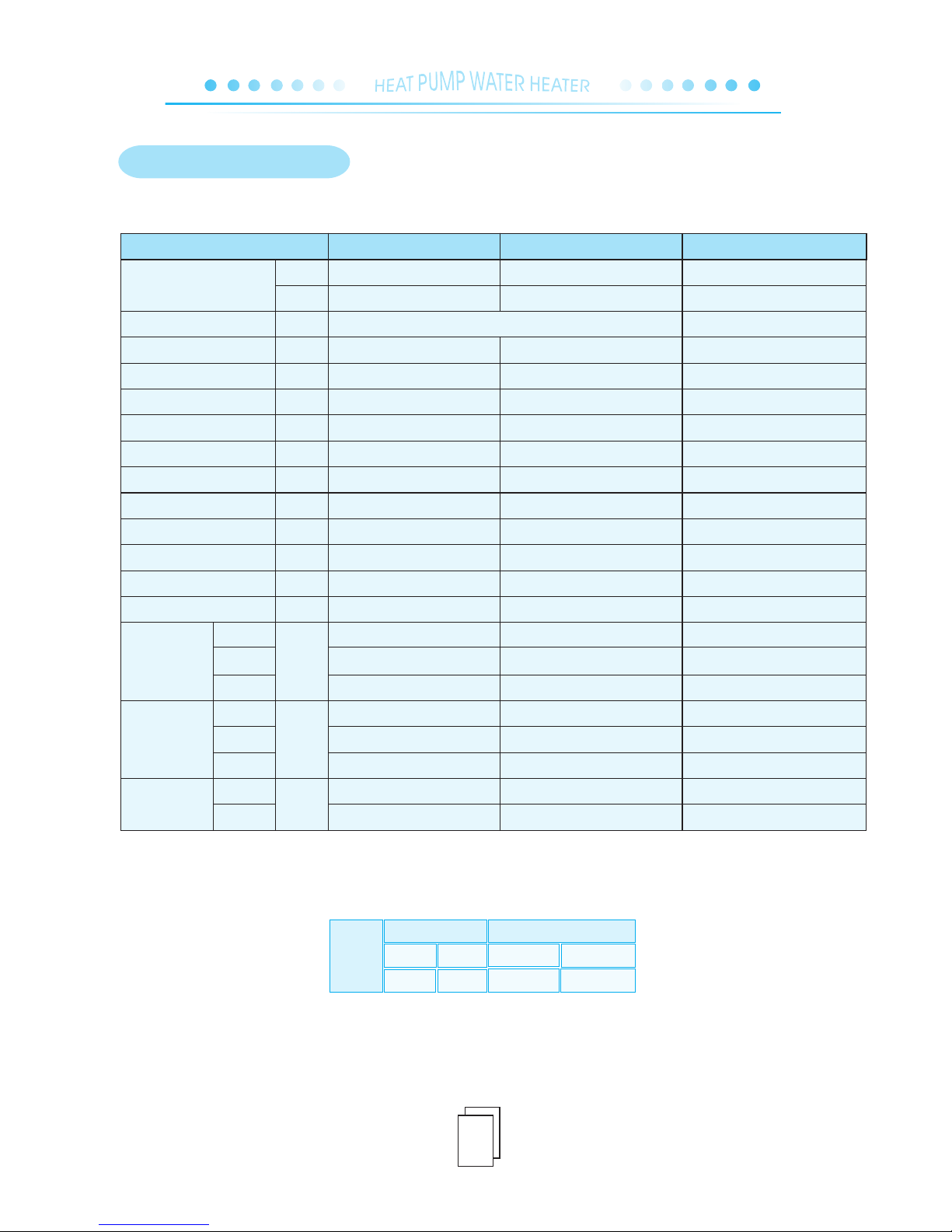
2.If any d is crepancies of d at a is found betwee n ab ove list and name pl ate on the heat pum p pl ease refer to the d at a on the
namepl at e as u pdated one.
2 0℃
1 5℃
4 0℃
4 5℃
Measuring
Conditions
Ambi ent Temperature Wat er Inlet/Outlet Temperature
Dry Bul b
Wet Bu lb
Inlet Temp Outle t Temp
L
W
H
L
W
H
W
BTU/h
V/PH/Hz
W
A
L/h
℃
℃
inch
W
RPM
dB(A)
mm
mm
kg
220/1/50
ITS-4.7HDP
4700
16000
1170
5.8
101
55
60
G 1 / 2
1
1
25
850
52
960
360
550
980
380
600
48
55
Power Supply
Input Power
Running Current
Hot Water Produced Volume
Thermostat Factory Setting
Maximum water temp
Water Connections
Compressor Quantity
Fan Motor Quantity
Fan Motor Input
Fan Speed
Noise
Ra ted He at ing C a pa cit y
Code
Net
Dimension
Packing
Dimension
Weight
Net Weight
Gross Weight
L
W
H
L
W
H
ITS-17VD
17000
58000
3600
17.2
290
55
60
G 1
1
1
90
850
58
660
660
960
740
700
990
118
126
3
3.PERFORMANCE DATA
380/3/50
ITS-24.5VD3
24500
83600
5000
9.3
420
55
60
G 1
1
1
150
750
58
660
660
960
740
700
990
123
132
Page 7
4
ITS-4.7HDP
2
2.5mm 13AWG
2
4.0mm / 11AWG
ITS-17VD ITS-24.5VD3
2
4.0mm / 11AWG
Code
Spec s
2.I nstal latio n
4.INSTALLATION
A
C
D
B
G
H
F
E
B SERIES
B
C
D E F
G
H
ITS-4.7HDP
A
280
360
935
940
55
155
520
550
Model
Size
Unit:mm
4.1. Dimensions
Page 8
5
A SERIES
D
H
G
F
E
D
G
E HF
Unit:mm
ITS-17VD
ITS-24.5VD3
960
960
660
660
190
190
660
6606060
Model
Size
Page 9
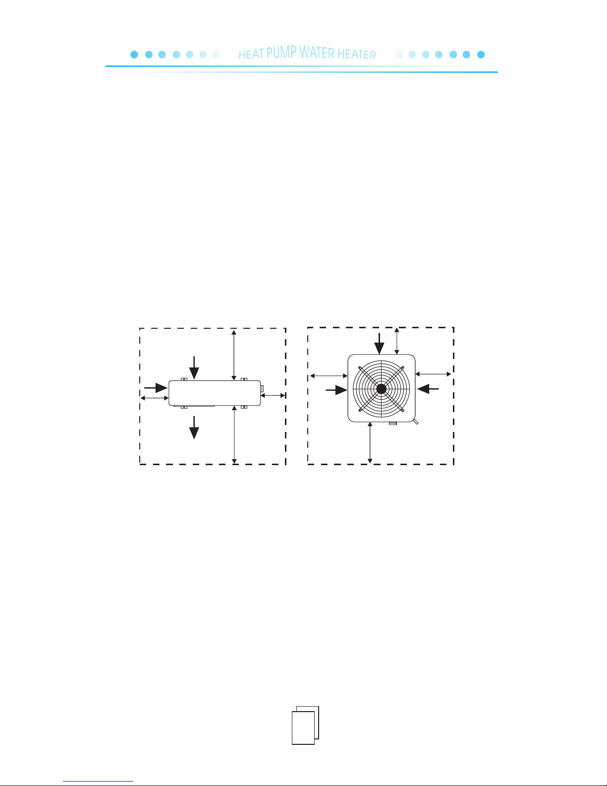
4.2. Free space for installation
6
◎
◎
◎
Water t a n k shou l d be i n places w i th a s u r r ou n di ng tempe r a t u r e of m o r e than 0℃.
It m a y be i n s t a ll e d outdoo r s or o n the r o o f of t h e build i n g (depen d i n g on t h e size o f the w a t er
ta n k and t h e bearin g ability o f the b u i ld i ng ) .
Do n o t place t h e water t an k in p l a ce s with p o l lu ti n g and c o r ro s iv e gas.
4.3.About water tank
◎
◎
◎
◎
◎
◎
◎
◎
It should b e instal l e d in p l a c es with l ar g e space a n d good v e nt i la ti o n.
The inst a llation posi t i on should guara n tee smooth air exh a l e (for air inhale , r e f er to the follow
-i n g figure) .
Position close to drainage chann el or vent to facilitate water di scha rge is st rongly recommended.
The inst a llation foun d a tion or bracket sh o uld be strong enou g h f or stable opera t i on.
Ma k e sure t h e unit k ee ps strai g h t up w i t h o ut any i n cl i na ti o n after i ns t al l at i on .
Do not i n s t a l l the m a i nf r am e in p l ac e where there i s pollution, corro sive gas, or accumulation
of dirt or falle n lea ves.
Avo id to i n s ta ll heat p u mp clo s e t o i n flammable an d e x plosive plac e s .
Ma k e sure t o obser v e the d i s t a nc e from hindrance shown b y arrows i n the f o l lo w in g figu r e .
Air o ut
Air i n
Air i n
Not l ess tha n 500mm
Not l ess tha n 2000m m
Not l ess
tha n 500mm
Not l ess
tha n 500mm
Not l ess tha n 500mm f rom the t op
Fre e space r equir ement f or the ho rizon tal hea t pump
Air i n
Air i n
Air i n
Mor e than 50 0mm
Not l ess tha n
500 mm
Not l ess tha n
500 mm
Not l ess tha n 1000m m
Not less than 3000mm from the top
Air o ut
Fre e space r equir ement f or the ve rtica l heat pu mp
Mod el: Vertic al Unit
Mod el: Hor izont al Unit
Page 10
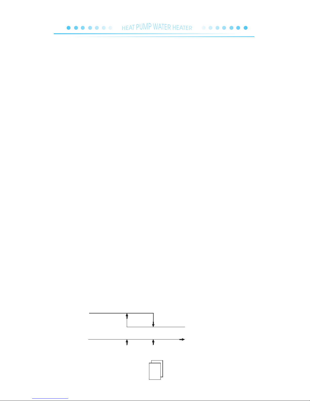
( - 5)set the water temperature set the water temperature
O N
water temperature
O FF
7
Operation procedure of heati ng: start the machine the unit water pump operates water flow switch
test the fan operates the compressor operates (when it shuts off at low water level, the water supply
electromagnetic valve will be open to supply water).
Operation control:
◎
◎
The pre-operation of the unit must be performed by professional technicians!
◎
◎
◎
When the whole system is checked and proves to meet the requirements, pre- operation can be started.
Switch on to start the heat pump, and compressor will start automatically in 3 minutes. For three-
phased power supply unit, check first whether the phases are in right order. Measure the ru nning
current of the compressor to see whether there is anything abnormal.
At least have heat pump running for 3 days for the pre-operation.
◎
◎
◎
◎
◎
The water leak pipe or water overflow pipe should be installed near the drainage channel or vent to
facilitate water discharge.
Water leak valve should be installed in the water leak pipe.
Before the electromotive electromagnetic valve in system pipeline, a check valve should be installed
for future check.
The customer's water pressure should be lower than 0 .6MPa.
ll the pipelines should use metallic pipes (such as stainless steel, steel pipes with plastic or stainless
steel linings, or thin-wall copper pipe). If plastic pipes are used (such as PP-R pipe and ABS pipe) the
expansion and contraction of t he pipes
between mainframe and water tank should be taken into account.
In winter, system water supply valve and break valve should be protected against the cold (based on
winter temperatures
in local area) in case the water supply pipe and valve should be frozen to break in winter.
4.4. Pipeline connection
4.6. Normal operation
4.5. Pre-operation
Page 11
8
Standby
status
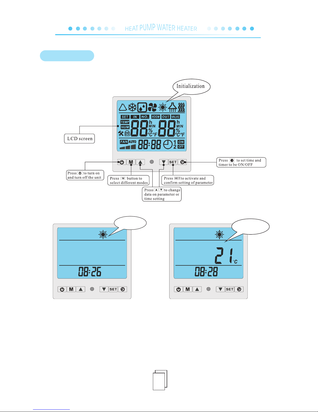
5.1. Controller illustration:
When heat pump is supplied with power, controller will display full screen, shows that it’s already
connected. If connection fails in 10 seconds, please check connections of communication cable or replace
anther controller.
◎ Under standby status controller displays time and running mode.
◎ Under running status controller displays time, water temperature in the tank and running mode.
Run ning st atus
Actu al tank water temp.
5. OPERATION
Page 12
9
5.2. Selecting mode
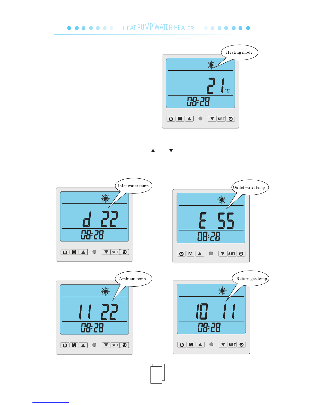
◎ Press "M"to select heating mode.
Remarks: Except heating mode is available,
other modes are in valid.
5.3. Checking current parameter
◎ Under standby status or running status press " "or" " controller will display from Parameter 0
to Parameter 13 in turn with current value. See more in table on next page.
◎ In about 5 seconds display will return to standby or running status interface.
Page 13

10
Remark s: 1 System amount i s re ferred to different m od els to be single or d ua l system.
2 Parame te r 12 : It must connec t th e copper thermo st at in attachmen t ba g to the PCB “Tank temperatur e ” co nnector,
before s ta rt up the heat pump , or c ontroller wil l di splay PP1 (Refe r to e rror code) an d he at p ump will not st ar t
5.4. Parameter table overview (Table 1)
0
1
2
3
4
5
6
7
8
9
A
B
C
D
E
F
10
11
12
13
Para meter
Desc ripti on
Rang e
Defa ult
Note
Reserv ed
Settin g de sired water tem p. in water tank
Defros ti ng cycle
Temp. point of ente ri ng defrosting
Temp. point of stop pi ng defrosting
Defros ti ng duration
Reserv ed
Memory r ec overy after pow er f ailure
Electr on ic expansion va lv e control (manu al /automatic)
Different work in g mode of water pum p
Reserv ed
Target s up erheat settin g
Manual c on trol of EE valve
Inlet wa te r temperature
Discha rge gas te mp erature
System c oi l temperature
Return -g as temperatur e
Ambien t te mperature
Reserv ed
Actual s te ps number of step m ot or in EE valve
1-30℃
10-60℃
30-90Min
0--30℃
2-30℃
1-12Min
1-2
0-1
0-1
0-1
0-1
-F-F
0-50
-9~90℃
-9~90℃
-9~90℃
-9~90℃
-9~90℃
-9~90℃
0-50
15℃
40℃
45Min
-7℃
13℃
8Min
2
1(with memory)
1(automatic)
1
0
2
35
Adjusted by technician
Adjustable
Adjusted by technician
Adjusted by technician
Adjusted by technician
Adjusted by technician
Reserved
Adjusted by technician
Adjusted by technician
Adjusted by technician
Reserved
Adjusted by technician
Adjusted by technician
Measured value
Measured value
Measured value
Measured value
Measured value
Measured value
Measured value
Αpplic ab le models:
ITS-4.7HDP
Page 14
11
Remark s: 1 System amount i s re ferred to different m od els to be single or d ua l system.
2 Parame te r 12 : It must connec t th e copper thermo st at in attachmen t ba g to the PCB “Tank temperatur e ” co nnector,
before s ta rt up the heat pump , or c ontroller wil l di splay PP1 (Refe r to e rror code) and he at p ump will not st ar t
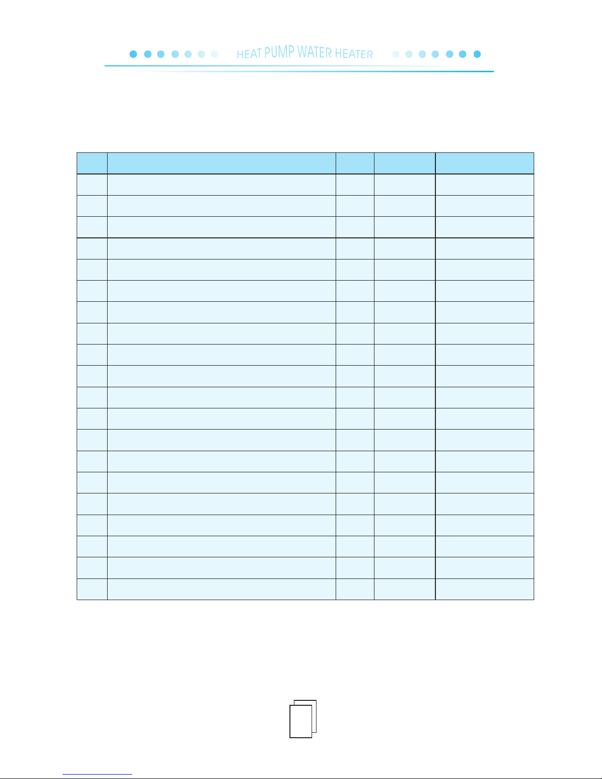
5.5 Parameter table overview (Table 2)
0
1
2
3
4
5
6
7
8
9
A
B
C
D
E
F
10
11
12
13
Para meter
Mean ing
Scop e
Defa ult
Note
Settin g of i nlet temp. to sta rt e lectric auxil ia ry HT1(option al )
Settin g de sired water tem p. in water tank
Defros ti ng cycle
Temp. point of ente ri ng defrosting
Temp. point of stop pi ng defrosting
Defros ti ng duration
System q ua ntity
Memory r ec overy after pow er f ailure
Electr on ic expansion va lv e control (manu al /automatic)
Reserv ed
Winte r an ti-freeze pro te ction
Target s up erheat
Manual c on trol of EE valve
Inlet wa te r temperature
Outlet w at er temperatur e
System c oi l temperature
Return -g as temperatur e
Ambien t te mperature
Wate r te mperature in th e ta nk
Actual s te ps number of step m ot or in EE valve
1-30℃
10-60℃
30-90Min
0--30℃
2-30℃
1-12Min
1-2
0-1
0-1
0-1
0-1
-F-F
0-50
-9~90℃
-9~90℃
-9~90℃
-9~90℃
-9~90℃
-9~90℃
0-50
15℃
40℃
45Min
-7℃
13℃
8Min
1 or 2
1(with memory)
1(automatic)
1
0
2
35
Adjusted by technician
Adjustable
Adjusted by technician
Adjusted by technician
Adjusted by technician
Adjusted by technician
Fixed by factory
Adjusted by technician
Adjusted by technician
Adjusted by technician
Adjusted by technician
Adjusted by technician
Adjusted by technician
Measured value
Measured value
Measured value
Measured value
Measured value
Measured value
Measured value
Αpplic ab le models:
IT S- 17V D IT S-2 4. 5VD 3
Page 15
12
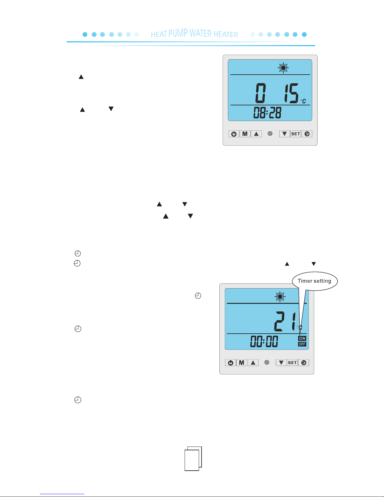
◎ Press " "controller displays from Parameter 0 to
Parameter 13 in turn with curren t actual value.
◎ Press SET to activate, controller displays flashing value.
◎ Press " " or " "to change value.
◎ Press SET again to confirm.
◎ Display will show confirmed value and return to standby
or running status interface in a bout 5 seconds.
NOTE: All parameters ca n be changed under sta ndb y or running status.
5.7. Setting time
◎ Press SET to activate time setting.
◎ When data of hour is flashing move" " or " " to fix it and confirm setting by pressing SET again.
◎ When data of minute is flashing move" " or " "to fix it and confirm setting by pressing SET again.
5.8. Setting TIMER ON/OFF
◎ Press to activate timer setting for ON, 00:00 and ON icon will be flashing together.
◎ Press again, controller displays with flashing hour and ON icon only, move " " or " "to
fix the hour on the timer to start on the unit.
◎ Operate in the same way to set the minute on the timer.
◎ After TIMER ON is completed continue to press to
activate timer OFF setting, 00:00 and will be flashing
with OFF icon, set and operate in th e same way .
◎ Press for final confirmation.
◎ Controller will display with O N and OFF if the timer
has been set.
◎ Press to activate, timer and ON/OFF will be both flashing.
◎ Press SET to cancel timer.
◎ When ON an d OFF doesn’t display on the controller timer has been cancelled.
5.9. Cancellation of TIMER ON/OFF
NOTE : TI ME AND TIMER SETTING CAN BE CHANGED U NDER STANDBY OR RUNN ING STATUS.
5.6. Setting Parameters
Page 16
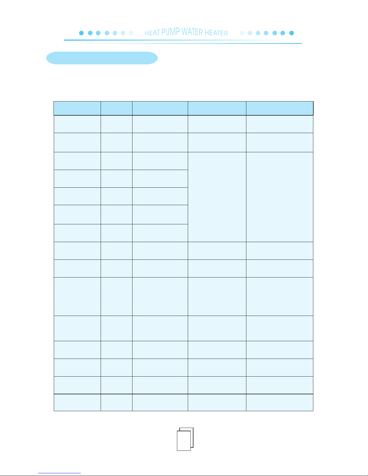
13
Wire
controlle r
PP1
PP2
PP3
PP4
PP5
PP7
EE1
EE2
EE3
EE4
EE8
☆●
(1 flashes & 1 pause)
☆☆●
(2 flashes & 1 pause)
☆☆☆●
(3 flashes & 1 pause)
☆☆☆☆●
(4 flashes & 1 pause)
☆☆☆☆☆●
(5 flashes & 1 pause)
☆☆☆☆☆☆●
(6 flashes & 1 pause)
☆☆☆☆☆☆☆●
(7 flashes & 1 pause)
☆☆☆☆☆☆☆☆●
(8 flashes & 1 pause)
☆☆☆☆☆☆☆☆☆●
(9 flashes & 1 pause)
☆☆☆☆……
(continuous flashes)
PP6
Communica ti on
failure
Defrostin g
Standby sta tu s
Com munic ation f ailur e
bet ween PC B and con troll er
Check if connection in good condition
or re pla ce ment ne ed ed.
Che ck if EE va lve bro ke n and
rep la cem en t neede d.
1.C heck if d ry filt er jamm ed .
2.F ailur e of E E val ve .
3.L ack of re fr ige ra nt.
1.To o much re fr ig er an t fi ll ed
in.
2.L iquid -like r ef rig er ant
flo ws from e va por at or in to
com press or.
3.E E valve f ailur e.
Too low amb ie nt te mp. and
wat er ente ri ng te mp .
1.D ischa rge cer tain re frige ra nt.
2.C heck an d adjus t EE valv e, make
sur e EE v alv e se nsor is w ell
con necte d with re tu rn ga s pi pe.
3.C heck if E E valve b roken a nd
rep la cem en t neede d.
Temp. sen so r bro ken o r not
eno ugh ref ri ger an t.
Temp. sen so r sho rt c irc uit
or op en c irc uit.
Che ck if tem p. sens or in goo d
con ditio ns, or re pla ce rela te d
sen sor.
1.C heck, repai r or repla ce f ilt er.
2.C heck if E E valve b roken a nd
rep la cem en t neede d.
3.R efill c ertai n refri ge rant.
No ac tion re qu ire d.
Rep lace te mp. sen sor or
fil l in cert ain ref riger an t.
Reserv ed
Reserv ed
Low work in g
pressure protection
High wor ki ng
pressure protection
Winte r an ti-freeze
protec ti on
Reserv ed
Ambien t te mp.
sensor f ai lure
Return g as t emp.
sensor f ai lure
System c oi l temp.
sensor f ai lure
Discharge gas temp.
sensor f ai lure
Inlet wa te r temp.
sensor f ai lure
Running sta tu s
OFF
OFF
ON
OFF
Prote ct ion/ Fai lu re
PCB LED indic at or
Possible ca us e
Check & solut io n
6. FAILURE CODE OVERVIEW
Applic ab le models:
IT S- 4.7 HD P
Page 17
14
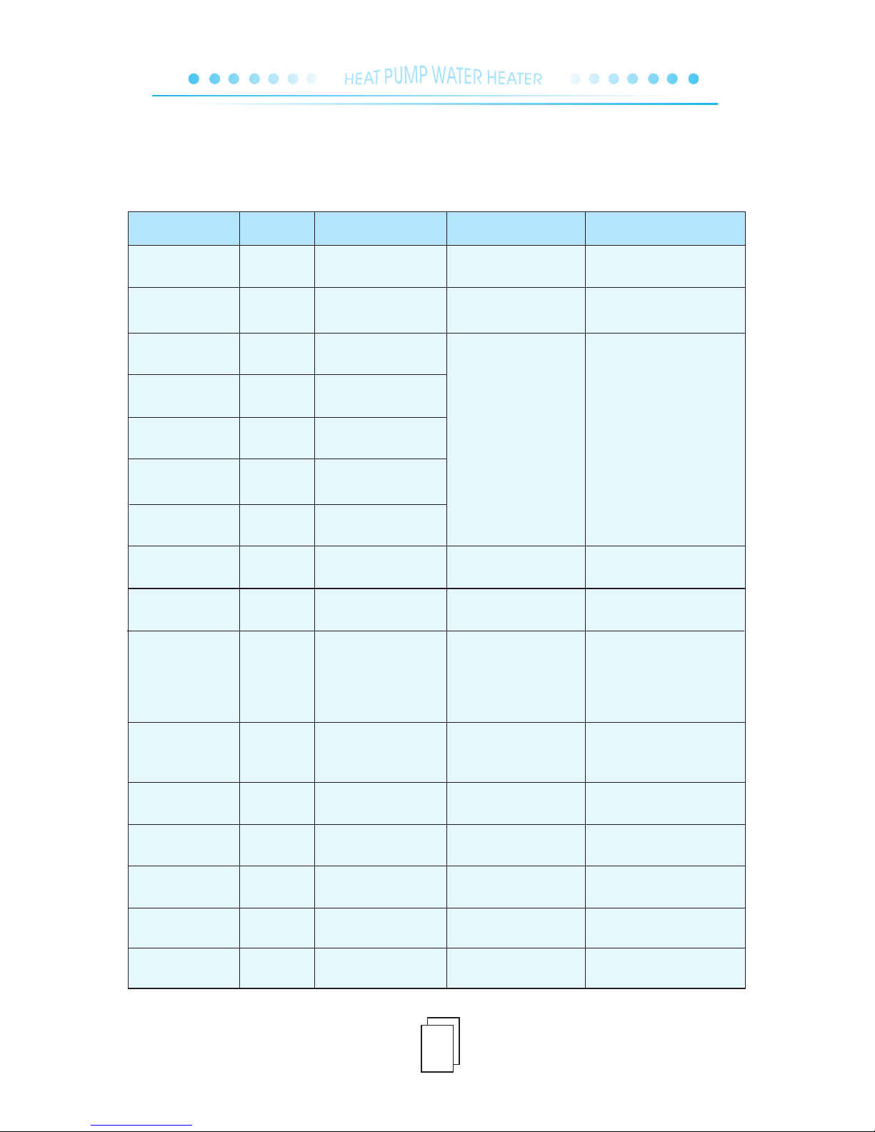
Wire
controlle r
PP1
PP2
PP3
PP4
PP5
PP7
EE1
EE2
EE3
EE4
EE8
☆●
(1 flashes & 1 pause)
☆☆●
(2 flashes & 1 pause)
☆☆☆●
(3 flashes & 1 pause)
☆☆☆☆●
(4 flashes & 1 pause)
☆☆☆☆☆●
(5 flashes & 1 pause)
☆☆☆☆☆☆●
(6 flashes & 1 pause)
☆☆☆☆☆☆☆●
(7 flashes & 1 pause)
☆☆☆☆☆☆☆☆●
(8 flashes & 1 pause)
☆☆☆☆☆☆☆☆☆●
(9 flashes & 1 pause)
☆☆☆☆……
(continuous flashes)
PP6
Communica ti on
failure
Defrostin g
Standby sta tu s
Com munic ation f ailur e
bet ween PC B and con troll er
Check if connection in good condition
or re pla ce ment ne ed ed.
Che ck if EE va lve bro ke n and
rep la cem en t neede d.
1.C heck if d ry filt er jamm ed .
2.F ailur e of E E val ve .
3.L ack of re fr ige ra nt.
1.To o much re fr ig er an t fi ll ed
in.
2.L iquid -like r ef rig er ant
flo ws from e va por at or in to
com press or.
3.E E valve f ailur e.
Too low amb ie nt te mp. and
wat er ente ri ng te mp .
1.D ischa rge cer tain re frige ra nt.
2.C heck an d adjus t EE valv e, make
sur e EE v alv e se nsor is w ell
con necte d with re tu rn ga s pi pe.
3.C heck if E E valve b roken a nd
rep la cem en t neede d.
Temp. sen so r sho rt c irc uit
or op en c irc uit.
Che ck if tem p. sens or in goo d
con ditio ns, or re pla ce rela te d
sen sor.
1.C heck, repai r or repla ce f ilt er.
2.C heck if E E valve b roken a nd
rep la cem en t neede d.
3.R efill c ertai n refri ge rant.
No ac tion re qu ire d.
Rep lace te mp. sen sor or
fil l in cert ain ref riger an t.
Phase pr ot ection
Reserv ed
Low work in g
pressure protection
High wor ki ng
pressure protection
Winte r an ti-freeze
protec ti on
Reserv ed
Ambien t te mp.
sensor f ai lure
Return g as t emp.
sensor f ai lure
System c oi l temp.
sensor f ai lure
Outlet w at er temp.
sensor f ai lure
Inlet wa te r temp.
sensor f ai lure
Running sta tu s
OFF
ON
OFF
Prote ct ion/ Fai lu re
PCB LED indic at or
Possible ca us e
Check & solut io n
Wro ng ph as e or la ck o f pha se
Che ck wire c on nec ti ons if ph as es
are c on nec te d in righ t or der.
☆☆☆ ☆☆☆☆☆☆●
(10 flashes & 1 pause)
☆
Reserv ed
EE5
Temp. sen so r bro ken o r not
eno ugh ref ri ger an t.
☆☆☆ ☆ ☆☆☆☆☆●
(11 flashes & 1 pause)
☆ ☆
IT S- 17V D IT S-2 4. 5VD 3
Applic ab le models:
Page 18
15
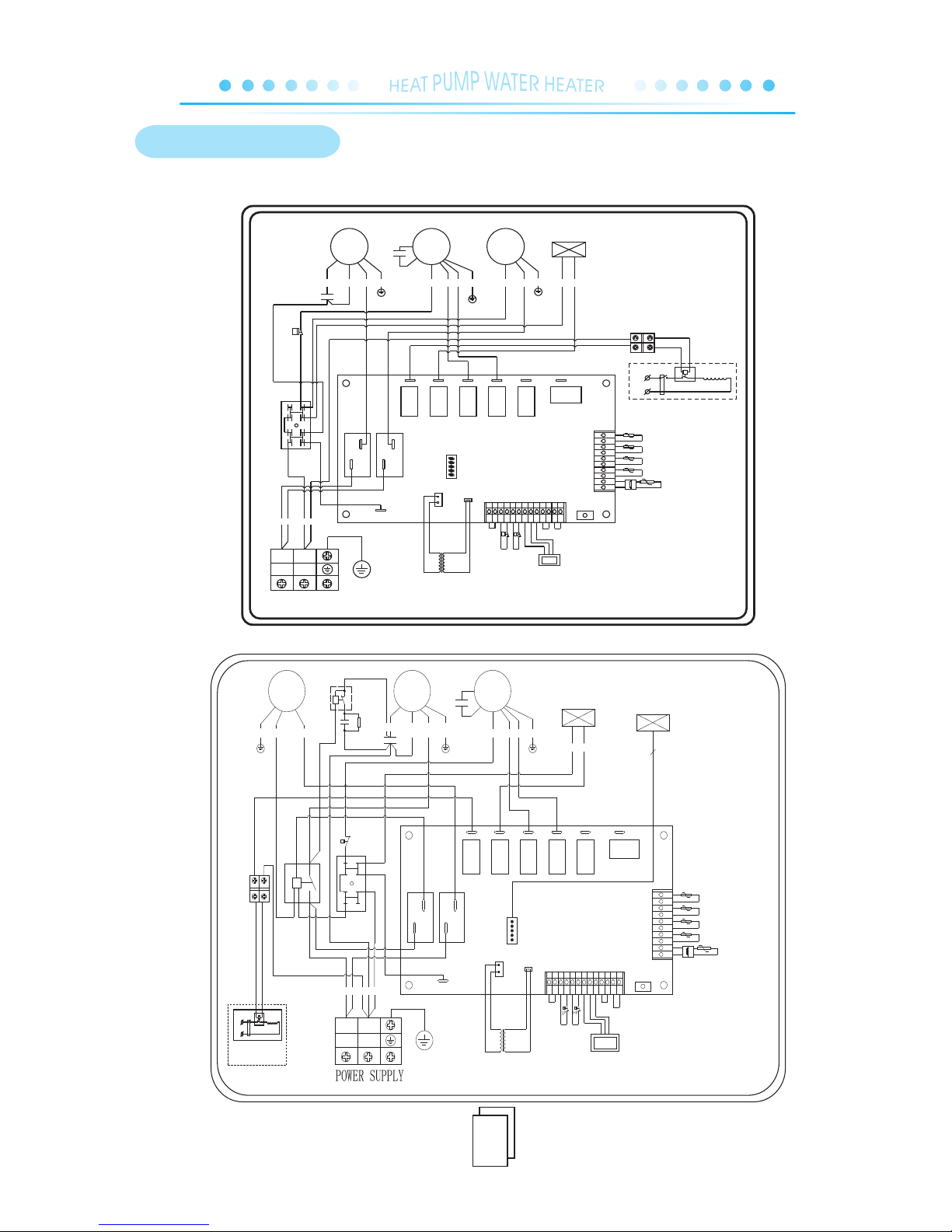
ITS-4.7HDP
ITS-17VD
7.WIRING DIAGRAM
POW ER SUPP LY
BLU
RED
Y/G
BLU RED
BLUBLUWHI BLK BLU Y/ G
RED
ORG
BLK
BLU
RED
Y/G
Wire con troll er
FQ
Ele ctric h eater o f
L
N
A1
A2
KM
ext ernal t ank
N2
L
L
hea ter
Ele ctric
4-Way
val ve
Mid dle
Fan
Fan
Hig h
OUT 2OUT 1
Exhaust temp
Return gas temp
Ambient temp
Coil temp
Tank s en so r co nn ec tor
Tra nsf or mer
N5
D01
D01
N4
N6
MP
P
11
1008
07
P
05
42
30
32
03
N
PUM P
N1
FNCM
NL
12V /AC
220 V/AC
LP H P
P
N1
B01
4-Way Valve
Hig h press ure
swi tch
Low p ressu re
swi tch
BL URE D
wi re co ntr oll er
RY 7
BL UBL U
PU MPCO MP
RY 6
4- Way
val ve
El ectr oni c
exp an di ng val ve
Transfor m er
P P
0708
101 1
Lo w pr es su re
sw itc h
sw itc h
Hi gh p re ss ure
03
32
30
42
05
Ta nk sen sor co nn ector
Coi l t em p
Am bi en t tem p
Back ga s t em p
Exh aus t tem p
P
6
N1
N2
FNCM
NL
12 V /A C22 0 V/ A C
AC -N
El ec tr o ni c
RE D
WH I BL K
S
R
C
C
C
BL U
OR G
BL K BL U RE D Y /G
Y/ G
L
L
N6
N5
D0 1
MP
K
PU M P
RE DBL UY /G
va lv e
4- Wa y
El ec tr i c
he at er
Hi ng
Fa n
Mi dd le
Fa n
2
C2
K
2
15
Rf
5
FQ
Ele ctric h eater o f
L
N
A1
A2
KM
ext ernal t ank
Page 19
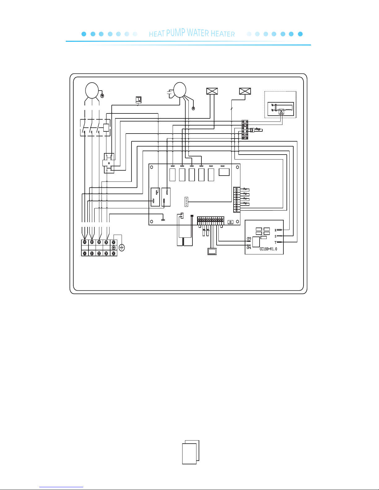
16
ITS-24.5VD3
MP
4- Wa y
va lv e
CM
UVW
N1
N
A1
A2
R S T
B
1 3 5
2 4 6
RE D BL K WH I
L1 1 L2 1 L3 1
WH I
BL KRE D
BU L
C NBA
AC 38 0V /5 0H z
FM
El ec tr on ic
ex pa nd in g
va lv e
6
D0 1B0 1
N1
N5
L
L
CO MP
PU MP
El ec tr ic
he at er
4- Wa y
va lv e
Hi ng
Fa n
Mi dd le
Fa n
El ec tr on ic ex pa nd in g va lv e
Tr an sf or me r
22 0 V/ AC
12 V/ AC
121110090807060504030201 13
HPLP
Hi g h p re s su r e s wi t c h
Lo w p r es s ur e s w it c h
07
08
10
11
Co il te mp
Am bi en t te mp
Re tu rn ga s te mp
Ex ha us t te mp
Ta nk se ns or
co nn ec to r
2322212018 191714 161 5
03
32
30
42
05
PO WE R SU PP LY
Wi re
co nt ro ll er
N4
D0 1
Wa te r pu mp
05
05
FQ
Electri c heater of
L
N
KM
external tank
Page 20

8. MAINTENANCE
.
.
.
.
.
.
.
.
.
.
.
.
The heat pump water heater is highly automatic equipment, which is checked periodically over its
unit state in application. If the unit can be maintained effectively for a long time, the operation reliability
and lifespan of the unit will be greatly enhanced.
1 The water filter installed outside the unit should be cleaned periodically to ensure a clean water supply
in the system in case the unit may be damaged due to the blocked dirty water filter.
2 In using and maintaining this u nit, the customer should pay attention to this point: all the safe ty
protection equipment in the unit has been set properly before leaving the factory, therefore, it is for
-bidden to adjust them without p ermission.
3 Check frequently whether th e power supply and electrical system connection of the unit are firm and
whether the electrical components operate abnormally. If there is, repair or replace in time.
4 Check frequently whether water supply of the system, water tank safety valve, liquid level controller,
and air discharge equipment operate normally in case air should enter the system to lead to decreased
water cycle so as to influence the heating ability of the unit and reliability of unit operatio n.
5 Check whether water pump and water pipe valves can operate normally, and whether there is any leak
-age in water pipeline and water pipe connections.
6 The surrounding of the unit should be kept clean with g ood ventilation. Clean regularly (1-2 months)
the air side heat exchanger to maintain a good heat exchange effect.
7 Check frequently the operation state of each part of the unit. Check whether there is oil dirt in unit
pipeline connection and air inhale valve to ensure there is no leakage of the unit refrigerant.
8 Do not pile any other object around the unit in case the air exhale should be blocked. The surrounding
of the unit should be kept dry and clean with good ventilation.
9 If the machine will be stopped for a long time, discharge the water in unit pipeline, cut off power supply,
cover with protection shield, and check the system comprehensively before starting the unit to operate
again.
10 If there is anything wrong with the unit and the customer can not solve it, make a phone call to local
special service department of our company so that we could send professional staff to fix it in time.
11 For cleaning of mainframe condenser, we suggest that 50℃-60℃ hot phosphate liquid with a density
of 15% can be used to clean it. Start the mainframe-equipped cycle water pump to clean for three hours
and then clean with running water 3 times. (In pipeline installation, it is suggested to reserve a tee
connection and block one of the connection with silk block) so as to connect pipes in cleaning. It is
forbidden to use corrosive detergent to clean the condenser.
12 Furring should be removed from the water tank after using for a period of time (usually two months
depending on water quality in local area).
17
 Loading...