

Page 1
OPERATION MANUAL
MODEL 6520x-NN
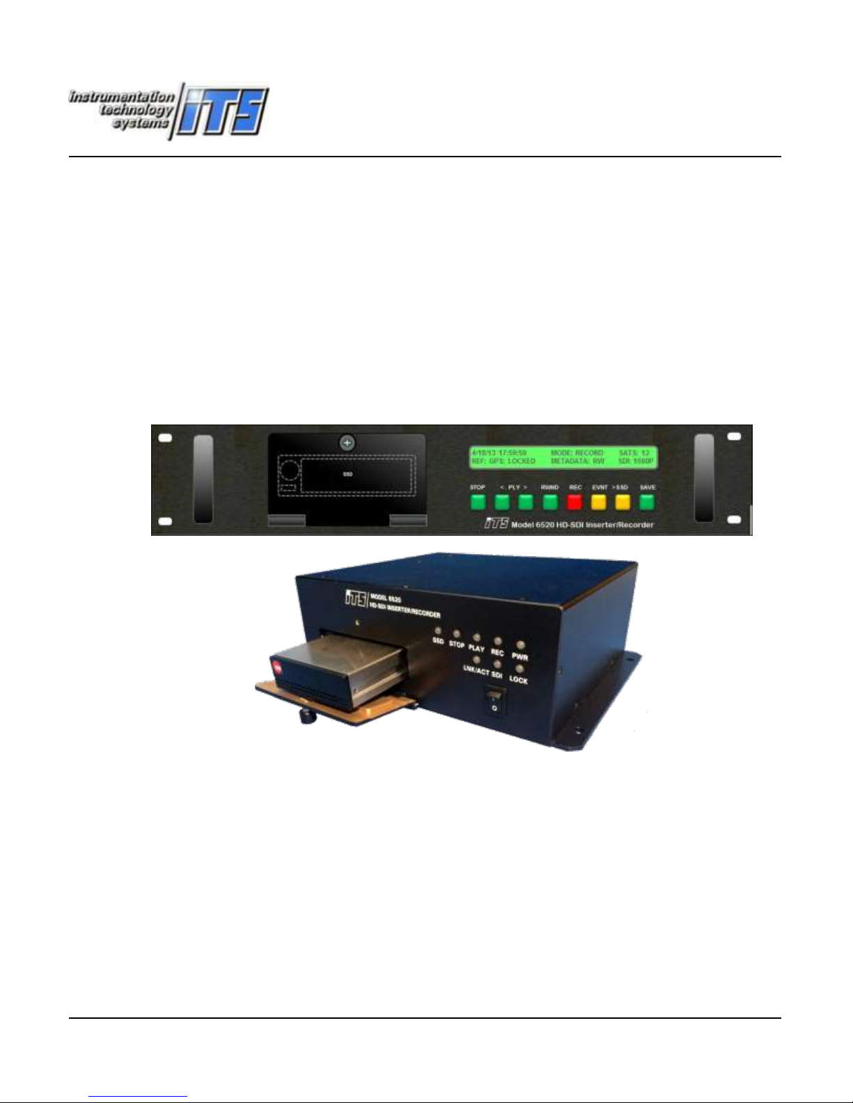
HD-SDI VIDEO INSERTER/RECORDER
19360 Business Center Drive ● Northridge CA ● 91324 ● (818) 886-2034 ● FAX (818) 886-7573
October 13, 2015
Page 2

ITS MODEL 6520x-NN
HD-SDI VIDEO INSERTER/RECORDER
Table of Contents
1.0 CHANGE HISTORY ..................................................................................................................................... 1
2.0 GENERAL .................................................................................................................................................. 2
3.0 CHARACTERISTICS .................................................................................................................................... 4
3.1 VIDEO INSERTER CHARACTERISTICS .......................................................................................................................... 4
3.1.1 Video Format .................................................................................................................................... 4
3.1.2 The Overlay Process ......................................................................................................................... 4
3.1.3 Alphanumeric Character Generator (ACG) ...................................................................................... 4
3.1.4 Movable Crosshair ............................................................................................................................ 4
3.1.5 Boresight Crosshair ........................................................................................................................... 5
3.2 TIME STAMPING AND SYSTEM CLOCK ....................................................................................................................... 5
3.2.1 Master Clock ..................................................................................................................................... 5
3.2.2 IRIG Time Reference ........................................................................................................................ 5
3.2.3 GPS Time Reference ......................................................................................................................... 5
3.2.3.1 GPS Dynamics Mode .................................................................................................................................... 6
3.2.3.2 Time Zone Offset.......................................................................................................................................... 6
3.2.4 NTP Time Reference (Not implemented at this release) ................................................................... 6
3.2.5 Stratum Clock (Option S) ................................................................................................................. 6
3.2.6 Rack Mount LCD Time Display ....................................................................................................... 7
3.2.7 Rack Mount and Remote Control Panel Controls ............................................................................. 7
3.2.8 Video Overlay Time Message ........................................................................................................... 7
3.2.9 Metadata Time Message ................................................................................................................... 8
3.3 RECORDER CHARACTERISTICS .................................................................................................................................. 8
3.3.1 Event Record (ER) .......................................................................................................................... 10
3.3.1.1 ER: DDR3 Only ............................................................................................................................................ 10
3.3.1.2 ER: DDR3 & SSD (only with SSD option) ..................................................................................................... 11
3.3.1.3 Rack Mount/Remote Control ER Operation ............................................................................................... 11
3.3.2 Continuous Record (Only with SSD option) ................................................................................... 12
3.3.3 Continuous Record with RM or Remote Panel ............................................................................... 12
3.3.4 Save DDR3 Clips to SSD automatically (requires SSD option) ..................................................... 12
3.3.5 SSD Operation ................................................................................................................................ 13
3.4 STATUS SCREEN ................................................................................................................................................. 13
3.4.1 Clip List .......................................................................................................................................... 15
6520 Inserter-Recorder Operation Manual Page i
Page 3

3.4.2 Live Monitor ................................................................................................................................... 16
3.4.3 Playback .......................................................................................................................................... 16
3.4.3.1 Playback using the Rack Mount or Remote Control Panel ......................................................................... 17
3.4.3.2 Selecting previously recorded clips ............................................................................................................ 17
3.4.4 Memory Clear ................................................................................................................................. 18
3.4.4.1 DDR3 CLEAR ............................................................................................................................................... 18
3.4.4.2 SSD CLEAR .................................................................................................................................................. 18
3.5 DDR3 OPTIONS ................................................................................................................................................. 19
3.6 SOLID STATE DISK (OPTION) ................................................................................................................................. 19
3.6.1 SSD File Names ................................................................................................ .............................. 19
3.6.2 Assembling your own SSD ............................................................................................................. 20
3.7 ETHERNET CONTROL/STATUS INTERFACE FUNCTIONS ................................................................................................ 20
3.7.1 Multi-Client Capability ................................................................................................................... 20
3.7.2 IP Keep Alive .................................................................................................................................. 20
3.7.3 UDP Discovery Capability .............................................................................................................. 21
3.8 CAMERA SYNC (CS OPTION)................................................................................................................................. 21
3.9 USER DEFINED KLV PACK ..................................................................................................................................... 22
4.0 MECHANICAL CONFIGURATION ............................................................................................................. 22
4.1 INSTALLATION INFORMATION ................................................................................................................................ 23
4.1.1 Cooling ............................................................................................................................................ 23
4.1.2 Rack Mount ..................................................................................................................................... 23
4.1.3 Shelf Mount .................................................................................................................................... 23
4.1.4 AC Power ........................................................................................................................................ 24
4.1.5 DC Power ........................................................................................................................................ 24
5.0 CONTROLS, INDICATORS, AND CONNECTORS ......................................................................................... 25
5.1 POWER ON/OFF ............................................................................................................................................... 25
5.2 LC DISPLAY ....................................................................................................................................................... 25
5.3 SHELF MOUNT STATUS DISPLAY ............................................................................................................................ 25
5.4 CONTROL BUTTONS ............................................................................................................................................ 25
5.5 IRIG IN ............................................................................................................................................................ 29
5.6 ETHERNET ......................................................................................................................................................... 29
5.7 CAMERA SYNC (OPTIONAL) .................................................................................................................................. 29
5.8 REMOTE ........................................................................................................................................................... 29
5.9 DISCRETE/SERIAL ............................................................................................................................................... 29
5.10 VIDEO IN .......................................................................................................................................................... 29
5.11 VIDEO OUT ....................................................................................................................................................... 29
5.12 POWER (AC) ..................................................................................................................................................... 29
5.13 POWER (DC) ..................................................................................................................................................... 30
6520 Inserter-Recorder Operation Manual Page ii
Page 4

6.0 SPECIFICATIONS ..................................................................................................................................... 31
6.1 VIDEO IN .......................................................................................................................................................... 31
6.2 VIDEO OUT ....................................................................................................................................................... 31
6.3 TIMING ACCURACY ............................................................................................................................................. 31
6.4 GPS PERFORMANCE ........................................................................................................................................... 31
6.5 GPS ANTENNA .................................................................................................................................................. 31
6.6 IRIG B INPUT .................................................................................................................................................... 31
6.7 METADATA TIMESTAMP ENCODING FORMAT .......................................................................................................... 31
6.8 USER DEFINED METADATA ................................................................................................................................... 32
6.9 ETHERNET PORT ................................................................................................................................................. 32
6.10 ALPHANUMERIC CHARACTERS ............................................................................................................................... 32
6.11 PACKAGE AND ENVIRONMENT .............................................................................................................................. 32
6.12 POWER INPUT ................................................................................................................................................... 32
7.0 OPERATION ............................................................................................................................................ 33
7.1 GENERAL .......................................................................................................................................................... 33
7.2 MANUAL CONTROLS ........................................................................................................................................... 33
7.3 WEBSERVER ...................................................................................................................................................... 34
7.3.1 About the 6520 Webserver.............................................................................................................. 34
7.3.2 Home ................................ ................................ ................................ ............................................... 34
7.3.3 Login (software option) .................................................................................................................. 35
7.3.4 Change Login .................................................................................................................................. 35
7.3.5 Communications ............................................................................................................................. 36
7.3.5.1 NTP Server Settings ................................................................................................................................... 37
7.3.6 Recorder .......................................................................................................................................... 37
7.3.6.1 STATUS ....................................................................................................................................................... 37
7.3.6.2 RECORDER CONTROL ................................................................................................................................. 38
7.3.6.3 SETUP ......................................................................................................................................................... 40
7.3.7 Inserter ............................................................................................................................................ 42
7.3.7.1 Record Channel .......................................................................................................................................... 42
7.3.7.2 Playback Channel ....................................................................................................................................... 45
7.3.8 Administrative ................................................................................................................................. 48
7.3.8.1 Date Format ............................................................................................................................................... 48
7.3.8.2 Time Source ............................................................................................................................................... 48
7.3.8.3 Time Zone .................................................................................................................................................. 48
7.3.8.4 Login required frame ................................................................................................................................. 48
7.3.8.5 Login Timeout frame .................................................................................................................................. 49
7.3.8.6 Show Status Screen .................................................................................................................................... 49
7.3.8.7 Reboot System ........................................................................................................................................... 49
6520 Inserter-Recorder Operation Manual Page iii
Page 5

7.3.8.8 RESTORE FACTORY DEFAULTS .................................................................................................................... 50
7.3.8.9 Format SSD................................................................................................................................................. 50
7.3.8.10 Clear DDR ................................................................................................................................................... 50
7.3.8.11 Clear SSD .................................................................................................................................................... 50
7.4 GRAPHICAL USER INTERFACE (GUI) UTILITY. ........................................................................................................... 51
7.5 GLOBAL GUI FUNCTIONS ..................................................................................................................................... 51
7.5.1 System Functions ............................................................................................................................ 51
7.5.2 The ADR ......................................................................................................................................... 52
7.5.3 Save Setup ................................................................................................ ....................................... 52
7.5.4 Load Setup ...................................................................................................................................... 52
7.5.5 Send Setup ...................................................................................................................................... 53
7.5.6 Send All .......................................................................................................................................... 53
7.5.7 Restore Factory Defaults ................................................................................................................. 53
7.5.8 Save Screen ..................................................................................................................................... 53
7.5.9 Clear Form ...................................................................................................................................... 53
7.5.10 Clear Screen ............................................................................................................................... 53
7.6 INSERTER TAB .................................................................................................................................................... 53
7.6.1 Common Controls ........................................................................................................................... 54
7.6.1.1 Embedded Fields ........................................................................................................................................ 54
7.6.1.2 Free Text Fields .......................................................................................................................................... 54
7.6.1.3 Annotation Parameters .............................................................................................................................. 55
7.6.1.4 Graphics Control ........................................................................................................................................ 55
7.6.2 Record Channel Inserter .................................................................................................................. 56
7.6.2.1 Metadata Time........................................................................................................................................... 56
7.6.2.2 Metadata Option Packs .............................................................................................................................. 56
7.6.2.3 Merge Embedded Field Data into Metadata ............................................................................................. 57
7.6.3 Playback Channel Inserter............................................................................................................... 58
7.6.3.1 MISB Metadata Timestamp ....................................................................................................................... 58
7.6.3.2 KLV Option Packs ....................................................................................................................................... 59
7.6.3.3 Creating A Field Display ............................................................................................................................. 59
7.6.4 Recorder Functions ......................................................................................................................... 61
7.6.4.1 DDR3 Frame ............................................................................................................................................... 61
7.6.4.2 SSD Frame .................................................................................................................................................. 62
7.6.4.3 Record Mode Frame .................................................................................................................................. 62
7.6.4.4 Record Frame ............................................................................................................................................. 63
7.6.4.5 Switched SDI Frame ................................................................................................................................... 63
7.6.4.6 Play Frame ................................................................................................................................................. 64
7.6.4.7 Stop ............................................................................................................................................................ 64
7.6.4.8 Rewind ....................................................................................................................................................... 64
6520 Inserter-Recorder Operation Manual Page iv
Page 6

7.6.4.9 Save ............................................................................................................................................................ 64
7.6.4.10 Status ......................................................................................................................................................... 65
7.6.5 Recorder Setup Functions ............................................................................................................... 66
7.6.5.1 Loop Length ............................................................................................................................................... 66
7.6.5.2 STOP DELAY ................................................................................................................................................ 66
7.6.5.3 PING-PONG ................................................................................................................................................ 67
7.6.5.4 Clear DDR ................................................................................................................................................... 67
7.6.5.5 Select a clip ................................................................................................................................................ 67
7.6.5.6 ERASE A CLIP .............................................................................................................................................. 68
7.6.5.7 FORMAT ..................................................................................................................................................... 68
7.6.5.8 CLEAR SSD .................................................................................................................................................. 68
7.6.6 SDI Switch ................................................................................................ ...................................... 68
7.6.7 KL metadata .................................................................................................................................... 69
7.6.7.1 Record Metadata- No Monitoring (Record Channel Metadata Write) ...................................................... 69
7.6.7.2 Record Channel Metadata Write with monitoring .................................................................................... 69
7.6.7.3 Starting Transport (metadata write in record channel) ............................................................................. 70
7.6.7.4 Display/Extract Metadata .......................................................................................................................... 71
7.6.7.5 Metadata display/extract setup ................................................................................................................. 71
7.6.8 GUI Configuration .......................................................................................................................... 73
7.7 RECORDER CONTROLS VIA KEYBOARD ..................................................................................................................... 73
7.7.1 Camera Sync (-CS Option) ............................................................................................................. 75
7.7.1.1 Timestamp Event ....................................................................................................................................... 75
7.7.1.2 Sync Format ............................................................................................................................................... 75
7.7.1.3 Rates .......................................................................................................................................................... 75
7.7.1.4 Delay .......................................................................................................................................................... 76
7.7.1.5 Time offset ................................................................................................................................................. 76
8.0 PROGRAMMING/SETUP ......................................................................................................................... 77
8.1.1 PROGRAMMING CONVENTION ............................................................................................... 78
8.1.2 REMOTE CONTROL FUNCTIONS ............................................................................................. 78
9.0 KL (METADATA) PACK .......................................................................................................................... 101
9.1 KLV METADATA VALUE DATA ITEM TYPES ............................................................................................................ 101
9.2 KLV PACK INTERNAL INSERTION FIELDS ................................................................................................................ 102
10.0 BINARY CODE UPLOADS ....................................................................................................................... 103
APPENDIX A: CAMERA SYNC OPTION SPECIFICATIONS...................................................................................... 105
APPENDIX B: AVAILABLE OPTION COMBINATIONS ........................................................................................... 106
APPENDIX C: REPRESENTATIVE PANEL DRAWINGS ............................................................................................ 107
APPENDIX D: CALCULATING FRAME CAPACITIES ............................................................................................... 108
APPENDIX E: DATA REQUEST ............................................................................................................................. 109
APPENDIX F: KL SOFTWARE TOOLKIT ................................................................................................................. 113
6520 Inserter-Recorder Operation Manual Page v
Page 7

KL OPTION OVERVIEW .................................................................................................................................................... 113
TRANSPORT DATA WITHIN THE HD-SDI VIDEO STREAM ....................................................................................................... 115
ABOUT THE KLV METADATA TOOLKIT ................................................................................................................................ 115
6520 Inserter-Recorder Operation Manual Page vi
Page 8

1.0 CHANGE HISTORY
Release Date
Change
12/18/2014
First Draft Release
4/29/2015
Added RM button functions and other updates, added paragraph 3.2.7 Rack Mount and Remote Control
Panel,3.3.4 Save DDR3 Clips to SSD automatically (requires SSD option), 3.4.3.1 Playback using the
Rack Mount or Remote Control Panel. Paragraphs have been added throughout to describe the rack
mount and remote panel button controls. These are found with images of the appropriate button to the
right of such paragraphs.
5/18/2015
Engineering Release
Added prototype Webserver and Configuration Utility forms and controls. Updated the event record
modes and updated the KLV Metadata reference information.
6/17/2015
Added 7.5 RECORDER CONTROLS VIA KEYBOARD section and promoted Programming and
Setup to a major paragraph (8.0)
Added Event Record after an event.
Added Event marker overlay command and descriptions (^Y??RRCCCL).
7/72015
Revised Input Channel and Output Channel references to Record Channel and Playback Channel
respectively. Added XHair controls to Webserver Inserter page and their explanations. Corrected
Metadata Timestamp controls to only permit writing metadata on Record channel.
7/8/15
Revised ^YTQ return message, changed recorder keyboard RECORD control to 0 and +
9/9/15
Updated specifications removed 2022-6 Ethernet download, updated webserver and GUI sections, added
new commands and completed command prototypes.
9/30/2015
Updated based upon DVT and details of controls that have changed.
10/13/2015
Added in Webserver updates and changes.
6520-nxHD Operation Manual Page 1
Page 9

1
HD-SDI Video Inserter/Recorder
2.0 GENERAL
The Model 6520 integrates the overlay, timing and metadata insertion capabilities of a 6055C-nGHD with
the capability of recording uncompressed video to volatile DDR3 or a non-volatile solid state disk (SSD).
Features include:
Accepts SD, HD and 3G SDI video sources per SMPTE 259M/292M/424M
Auto-detects and formats insertion for 480i, 576i, 720p and 1080i/p for both NTSC and
PAL field/frame rates
Records continuously to SSD (1TB) up to 172K Frames 1080p/60 Uncompressed
Event/Loop record up to 5.8K Frames 1080p/60 Uncompressed
Save more than 32 event clips to SSD
Live Monitor Video while recording
Plays back HD-SDI
Inserts, decodes and can overlay MISB 0605.3 format compliant timestamp and up to 2
SMPTE 291M Type 02 KLV metadata packs of user formatted data in VANC space1
Inserts up to 3000 characters of alphanumeric data on each video frame
Inserts movable and fixed boresite crosshairs independently in color.
HD-SDI playback speeds: 1/32x-1x slow motion, single-frame stepping, or search 2x-32x
Extracts data of KLV metadata to Ethernet data file frame x frame with/without timestamps
Clear DDR3 and/or SSD compliant with DOD 5220.22-M
Camera Sync (optional); GPS/IRIG phase locked with adjustable offset
TTL strobe aligned with Camera Sync with adjustable delay
Disciplined Stratum 3 (Optional) clock delivering < 5µs/hr unlocked drift
Synchronizes time to within 25±20 ns of the GPS time mark generated by an internal 12
channel GPS receiver or 5±3µs of and applied IRIG.
Samples time to 3±2µsec of any vertical sync (EAV) detected in the SDI video stream.
Inserts time as collected from GPS, IRIG or read from previously recorded metadata in a
selectable resolution from 1second to 1µs.
Records collected time to a 1 µs resolution into the MISB Microsecond Timestamp when
processing 720 and 1080 formats
Remotely controlled via Ethernet port by commands, ITS GUI or embedded webserver.
There are four modes of recording possible; Event Record (ER), ER and-save event clips to SSD, event
record to DDR (pre-event) and SSD (post event) or Continuous Record to SSD. An internal DDR3
facilitates ER where 6520 can be set to continuously record incoming HD-SDI video in a “loop”. The loop
length is programmable from 10 frames to the capacity of the DDR3. When in ER mode, the recorder will
Metadata is not supported for SD/SDI (480i/576i) video.
6520 Inserter-Recorder Operation Manual Page 2
Page 10

continuously record the number of frames set by the user (up to 26,000; 480i). On trigger, either a discrete
input or command via Ethernet, the recorder will continue to record the number of post event frames
previously specified by the user. The result is a clip surrounding the event. Another event mode will
continuously record to the loop length as before, but when the event is marked, the entire loop as recorded
prior to the event marker will be saved to SSD and recording will continue until a STOP is commanded or
the capacity of the SSD is exhausted. The clip may played back and presented as SDI to the output video
port. Event recording has many benefits including the capture of important video sequences with a
minimum of control input and highly efficient use of the SSD capacity.
The 6520 includes a live monitor channel that is active while recording. Video presented at this port while
recording is less than 8µsec behind real time. The live monitor channel includes a metadata decoder and
overlay engine. These capabilities enable one to monitor not only the video, but the data being captured in
the metadata. The record and playback channels have the capability to independently overlay text, time and
crosshairs.
The 6520 records and plays back all HANC (payload, AES audio and other metadata) and VANC metadata.
Text and crosshairs may be overlaid at record time. More importantly MISB format metadata timestamps
and up to two user defined KLV metadata packets may be recorded with each frame1. At playback the
metadata may be decoded and overlaid if desired and concurrently extracted to the Ethernet port as a data
stream. This data set may include the timestamps permitting exact identification of the frame with which
each block of data was collected.
During any playback, the video may be stopped, played back 1 frame at a time or at 1/32xFR to 1xFR in 32
in either direction where FR is the original frame rate of the recorded video. Search may also be
accomplished at 2xFR to 32xFR in either direction. Playback speeds greater than the originally recorded
frame rate is accomplished by frame skipping.
Metadata packs are SMPTE 291M type 02 structures the content of which may be designed using ITS KLV
SOFTWARE TOOLKIT or software supplied by others. The ITS toolkit is currently delivered at no
additional cost with all of our HD-SDI video products having the KLV capability.
Source video may be 720p or 1080p at 25, 30, 50 and 60 frames/sec (also at the NTSC comparable rates).
Source video may also be 480i/60 or 1080i/60 also at the NTSC comparable rates. Frame formats supported
comply with SMPTE 274M (1080) SMPTE 296M (720) and SMPTE 125M (480); ITU 709 10-bit 4:2:2
sampling. The 6520 will detect the format and synchronize to any of these formats automatically. No user
intervention is required. Clips may be of different formats as well.
When the camera sync option is purchased, the 6520 may be programmed or if the camera always outputs
SDI, will auto detect the camera format (must be one of the supported formats) and set the tri-level sync
(TLS) to match. TLS may be phase locked to either GPS or IRIG. TLS may also be delayed in 1µsec steps
to 32 msec in order to synchronize actual picture taking across a variety of imaging technologies (e.g. CCD,
CMOS, IR). Supporting data collection time coherent to imagery, the camera sync option also provides a
TTL strobe output that may be adjusted ±16ms in 1µ steps to help align data acquired with each image.
The 6520x-NN may be ordered in a shelf mount or 19” 2U rack mount enclosure. Input power
may also be specified at order to support 10-36 VDC (power adapter is available), or by 100 to
240VAC 50/60 Hz.
6520 Inserter-Recorder Operation Manual Page 3
Page 11
3.0 CHARACTERISTICS
3.1 Video Inserter Characteristics
3.1.1 Video Format
The 6520 will accept and automatically synchronize to 480i/60, 576i/50, 720p and 1080i 10-bit
4:2:2 encoded video (ITU 709 or ITU 601 for 480i/576i). Serialization formats (SDI) supported
are defined in SMPTE 259M for SD, 292M and 424M for HD, i.e. 720p/1080i HD and 1080p
respectively at 25 (576i), 29.97 (480i, 1080), 30 (576i, 1080),50 (576i), 59.94 (720,1080) and 60
(720,1080) frames per second.
3.1.2 The Overlay Process
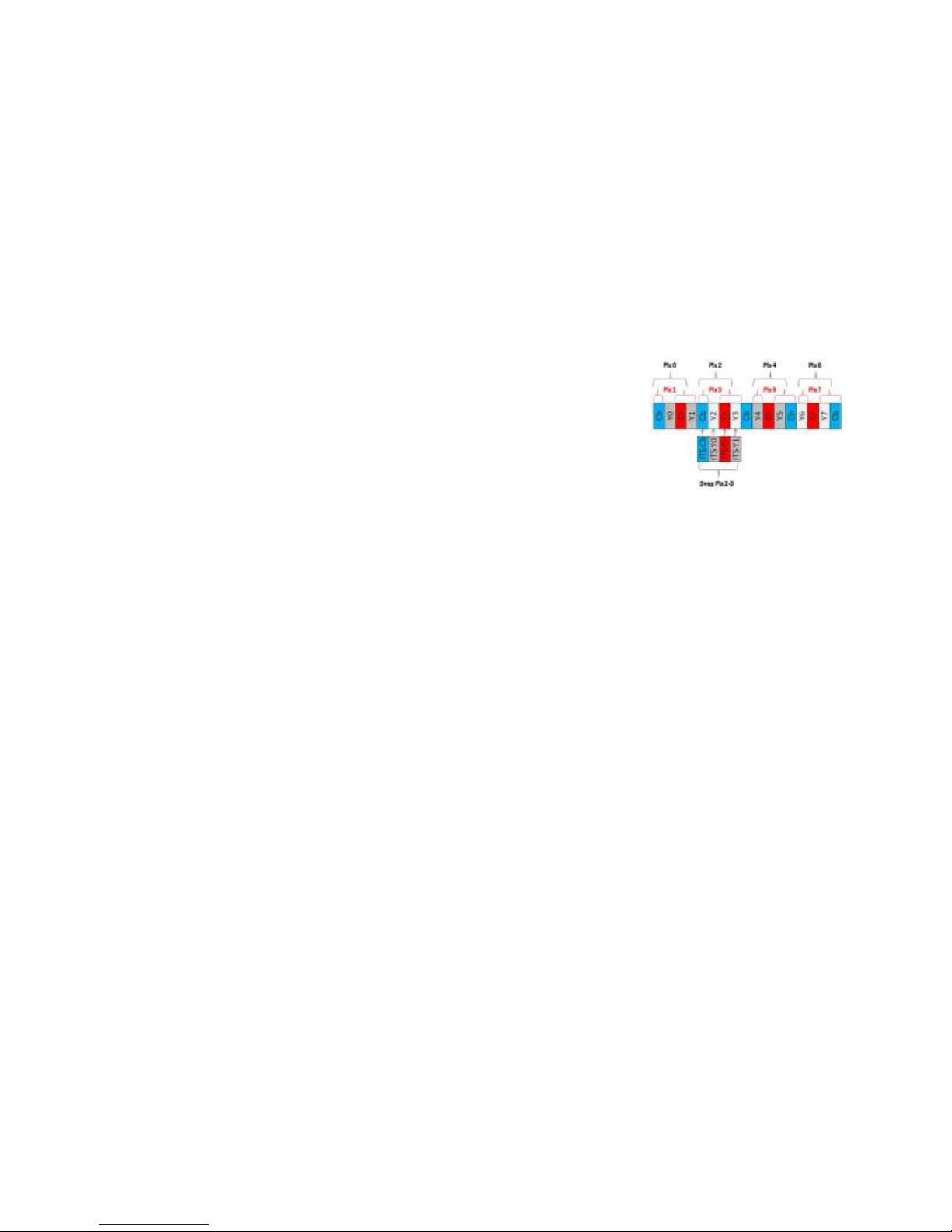
The ITS SDI Insertion Engine stages the bit maps necessary to represent the characters to be
displayed on the video. As the input SDI is decoded, picture elements
(pixels) are substituted in real time placing characters at the selected
color into the video. There is no image buffering, prescaling or other
image modification performed within the engine. The total end-to-end
latency is less than 4 frames from source input to recorded media. The
pixel substitution process only replaces the source video where needed
to represent the characters or graphic being overlaid on the video. Since
text and graphics (crosshairs) colors may be independently chosen from a palette of eight (black,
white, red, green, blue, cyan, magenta and yellow), there is no need for a background field to offer
high contrast to render text and graphics readable over a wide range of video scenes. The result is
little obscuration of the source video.
3.1.3 Alphanumeric Character Generator (ACG)
The 6520 includes an ACG that provides the capability of placing ASCII character strings in the
video frame. The characters are described on a 7x9 matrix where each aspect is two image pixels
high/wide. This is the base size. The character size may be doubled horizontally, vertically or both
by the user. The character colors of black, white, red, green, blue, cyan, magenta and yellow are
selectable independently for each channel (record and playback).
The system uses "column, row" coordinate addressing. The range of rows is from 12 to 36 and the
range of columns is from 20 to 110. The limits of each range depend on the character size selected
and the incoming video format. Intensity of the overlay color may also be adjusted from full
saturation to black. Size selection is made either remotely, or GUI, or embedded webserver.
3.1.4 Movable Crosshair
A crosshair is inserted and positioned as selected by the operator. The crosshair may be inserted
into the live monitor channel while recording, the recording channel or both. The color and
position of the crosshair is controlled via Ethernet port (commands or GUI) or the RS-232
(commands or GUI) port and will remain displayed until disabled.
The crosshair format is selectable as full screen, medium or small. When small is selected, the
crosshair will occupy approximately 20% of the vertical size of the video frame. The movable
crosshair color is selectable by the user and may be different from the fixed crosshair and the color
selected for text overlay. The movable crosshair can be positioned at two-pixel resolution x
(horizontal) and y (vertical) relative to the center of the picture area (i.e. 0,0 is the center pixel).
The crosshair is two pixels wide and two lines high.
6520 Inserter-Recorder Operation Manual Page 4
Page 12

2
3.1.5 Boresite Crosshair
A fixed boresite crosshair may be inserted in the live monitor channel, recording channel or both.
It is located in the precise center of the video frame under command of the operator via the
Ethernet port (GUI, webserver or commands). The boresite crosshair format is selectable as full
screen, medium or small. When small is selected, the crosshair will occupy approximately 20% of
the vertical size of the video frame. The color of this crosshair is user selectable and may be
different than either the movable crosshair or text overlay.
3.2 Time Stamping and System Clock
3.2.1 Master Clock
The 6520 incorporates a disciplined master clock which uses the interval between one-second
marks decoded from a GPS, IRIG B or NTP source to calibrate the master clock. Assuming there
are sub-millisecond differences between these time references sources, jam sync only occurs
once2. That is the clock is jam-synchronized to time after power up on first lock to the selected
time reference or when the time reference is changed.
The master clock when not locked to a time reference (GPS, IRIG B or NTP) will keep time but
will drift from the time of last synchronization. The rate of drift will be approximately 1.1
millisecond/hr when the TXCO oscillator is present and approximately 4µs/hour when the S3
option is purchased (see 3.2.5 Stratum Clock (Option S) page 6 for details).
3.2.2 IRIG Time Reference
The 6520 may be synchronized to an external IRIG B time reference. This source may always be
connected. The time reference selection is made with the GUI, webserver or command.
When locked to IRIG, the 6520 master clock is disciplined by the IRIG B source and synchronized to
5±3 microseconds of the encoded one-second time mark. The time display will be preceded by an
uppercase “I” when locked. When a lowercase “i” is present it indicates that IRIG is the selected time
reference source but the system is not currently locked.
If IRIG lock is lost and the NTP client is enabled (see NTP Time Reference (Not implemented at
this release)), the 6520 master clock will attempt to lock to NTP. If the 6520 successfully locks to
NTP, the time display will be preceded with “N”.
When IRIG B lock is reestablished, the master clock will resume synchronization with IRIG B
automatically. If the NTP client is not enabled and IRIG lock is lost, the master clock will keep
time and may drift from the last synchronized time as described earlier.
3.2.3 GPS Time Reference
The internal GPS receiver is always active. This time reference is selected by command remotely.
When GPS is selected and GPS is locked, the master clock is disciplined by the internal GPS
receiver and synchronized to 30±20 ns of the GPS time mark when GPS Dynamics Mode is set to
FIXED and the unit is in a fixed location.
If GPS lock is lost and the NTP client is enabled (see NTP Time Reference (Not implemented at
this release)), the 6520 master clock will attempt to lock to NTP. If the 6520 successfully locks to
NTP, the time display will be preceded with “N”.
Other jumps may occur after long periods of free run without clock to a time reference.
6520 Inserter-Recorder Operation Manual Page 5
Page 13

When GPS lock is reestablished, the master clock will resume synchronization with GPS
automatically. If the NTP client is not enabled and GPS lock is lost, the master clock will keep
time and may drift from the last synchronized time as described earlier.
3.2.3.1 GPS Dynamics Mode
The GPS has a programmable Dynamics Mode feature that may be set by the operator using a
command. This provides the maximum time accuracy achievable for the given application by
optimizing the GPS receiver for a fixed installation or one in motion. Mode values of, 1 for “Fixed
Base Station” or 2 for “Man Walking”, 3 for “Land Vehicle”, 4 for “Marine Vehicle” and 5 for
“Airborne” environments are possible. The mode is selectable by command via the Ethernet port.
Mode 1, Fixed Base Station, provides the maximum time accuracy. Once entered the value is
stored in non-volatile memory.
3.2.3.2 Time Zone Offset
In order to display local time, when locked to GPS, a time zone offset of ±12 hours in 15-minute
increments may be entered by the user by the ^YTZ command via Ethernet. This value is saved in
internal FLASH memory and thus survives power cycling. The time zone offset is not applicable
when using an IRIG B or NTP reference.
3.2.4 NTP Time Reference (Not implemented at this release)
An NTP client function is integrated into the 6520 Inserter-Recorder. The system intent is that NTP is
a “fail-over” function in that if no GPS lock or IRIG lock is achieved, the NTP client (if enabled) will
attempt to lock to the NTP server address entered by the operator. If GPS and/or IRIG lock is lost for
30 seconds or more, and the NTP client is 6520 NTP Client function will attempt to connect to an
NTP server. The 30 second delay prevents temporary lost lock conditions from cause multiple time
jumps in the time master
The NTP client function is enabled by entering a valid Stratum 1 NTP server TCP/IP address into the
system. This is accomplished by command or the webserver. This value may be saved to internal
FLASH such that this address survives power cycling. The NTP server selected must be a Stratum 1
time reference.
If the NTP server addressed is qualified as a Stratum 1 and the baseline round trip of time messages is
consistent, the NTP client will begin the synchronization process automatically. This may take
30 seconds to accomplish.
When locked to NTP, the time accuracy is held to within 3µ seconds of the NTP server time.
The NTP Client function is disabled when an NTP Server Setting (address) value is set to 0.0.0.0.
Any address set must, of course, be a valid and available NTP Server in order for the 6520 Client to
connect and synchronize to it.
In the absence of a GPS signal, IRIG signal or NTP server, 6520 master clock may be set by the user
via command over Ethernet. Any such manually set time will be overridden by the GPS, IRIG or
NTP time value when lock is achieved.
3.2.5 Stratum Clock (Option S)
An available option replaces that standard 0.3 ppm crystal oscillator with a 10 ppb oven
temperature controlled stratum 3 oscillator. When installed, time drift of the disciplined master
clock from a previously locked (either GPS or IRIG reference for at least 20 minutes after oven
temperature stabilization) condition is less approximately 4 µsec per hour over the full operating
6520 Inserter-Recorder Operation Manual Page 6
Page 14

temperature range. There is a minimum 10 minute warm up time. The minimum power on time
to achieve the total 10 ppb stabilization is approximately 2x the off time for periods of 24 hours or
less. For extended off times the stabilization time required is 48 hours + ¼ of the off time but not
longer than 6 days.
This option is not field upgradable and must be selected at the time of order. This option is
included with the Camera Sync Option at no additional cost.
3.2.6 Rack Mount LCD Time Display
In the rack mount package, time displayed in the LCD on the front panel may be left at UTC. The
default format is xDDD:HH:MM:SS.ssss, where a lower case value of x (“g”, “i” or “n”) that the
system is not currently locked to neither GPS, IRIG B or an NTP server and therefore, the time is
produced by the internal clock. A “^” will be displayed to the left of the time message to alert the
operator that the time is not derived from a locked reference. When the x location is blank, it indicates
that either GPS or IRIG B is locked or NTP synchronization is achieved.
A start of NTP (Not implemented at this release) frequency lock is indicated when the front panel
display of the 6520 replaces the REF: GPS with REF: xxx.xxx.xxx.xxx. The value of
xxx.xxx.xxx.xxx is the address of the NTP server providing time synchronization. The LCD will also
replace the “SAT IN VIEW XX” status with “Offset: 99µs”. The offset will change to a non-zero
value when lock is achieved.
3.2.7 Rack Mount and Remote Control Panel Controls
The rack mount package and shelf mount remote control panel offers
recorder functionality without any connection to Ethernet with the
integration of eight (8) momentary pushbuttons. These controls enable the
operator to
1. Record to DDR3 or SSD (>SSD).
2. Save a clip recorded in DDR3 to SSD (SAVE).
3. Initiate ER mode using previously set loop length and post event frame count (EVNT).
4. Play a clip (< PLY >).
5. Select the clip playback source; either DDR3 or SSD
6. Search, single step or slow-motion view a clip either forward or backward (<PLY>)
7. Rewind to the beginning of the current (RWND).
8. Output an SDI Green Screen with status information while in STOP (STOP)
9. Stop play or record operation immediately (STOP, <PLY>, REC)
Each pushbutton is illuminated as necessary to indicate mode and status.
Operation of each of these controls is described throughout and outlined in paragraph 5.5 Control
Buttons on page 29.
3.2.8 Video Overlay Time Message
The time is sampled on each decoded SDI vertical sync (EAV signature) to an accuracy
3±2 µsecond of the synchronized time (derived from GPS, IRIG B or NTP). The time value
acquired may then be overlaid on the video field/frame initialized by this vertical sync. The time
may also be recorded as metadata (SMPTE 291M Type 02 KLV metadata packet formatted as a
Microsecond Timestamp per MISB 0605.3) when processing 720 or 1080 video formats.
A time message inserted on the video may be displayed in a user selectable resolution from 1
second to 1 microsecond in decade increments. The time message may be placed anywhere on
6520 Inserter-Recorder Operation Manual Page 7
Page 15
3
the active video area. Position is selected by specifying row, column and time resolution by
command, webserver or the GUI. The color and size are parameters selected for text overlay.
A command is available to send a serial time message out of the Ethernet and/or RS232 serial port.
The time reported may either be GPS, NTP (when available), IRIG or internal clock time.
The time message may be overlaid on the video being recorded, or only on the live monitor video
channel leaving the recorded video free of overlay.
3.2.9 Metadata Time Message
A remote command, webserver or GUI input can set the 6520 to insert the acquired time to a
VANC KLV packet formatted in accordance with MISB 0605.3. The MISB format stores time as
a 64 bit word representing microseconds from January 1, 1970; the UNIX epoch. The time
captured initiated by the vertical sync (EAV) is written to line 9 of the same frame that vertical
sync triggered time-capture. These conditions are present in 720 and 1080 formats only.
If the time has previously been encoded into a KLV metadata packet (i.e. during playback from the
DDR3 or SSD), that value may be read and overlaid onto the playback video. The metadata time
message may be placed anywhere on the video in row, column locations in a manner similar to that
used to insert the GPS/IRIG/NTP time message. When displayed, metadata time is prefixed with
an “M” if at the time it was written to the packet if the master clock is synchronized to a reference
(GPS, IRIG or NTP) or “m” if not synchronized to a time reference. If no metadata is present the
time message displayed is “-No Metadata-“. This time may be displayed in the corresponding
video when selected.
3.3 Recorder Characteristics
A recording saves uncompressed video including all HANC and VANC space. Therefore all
metadata (e.g. sound, workflow, timestamps and user defined keys) is recorded and remains a part
of each recorded frame.
SDI video in may be SMPTE 259M (480i/60)3, SMPTE 292M (720p/60 or 1080i/60) or
SMPTE 424M (1080p/60) HD-SDI video source. Frame rates supported for recording and
playback are 29.97, 30, 50, 59.94 and 60 fps as permitted by the frame format. Input and playback
output frame formats are in accordance with SMPTE 124M (480/576) SMPTE 274M (1080) or
SMPTE 296M (720) for 4:2:2 sampled and multiplex 10-bit video.
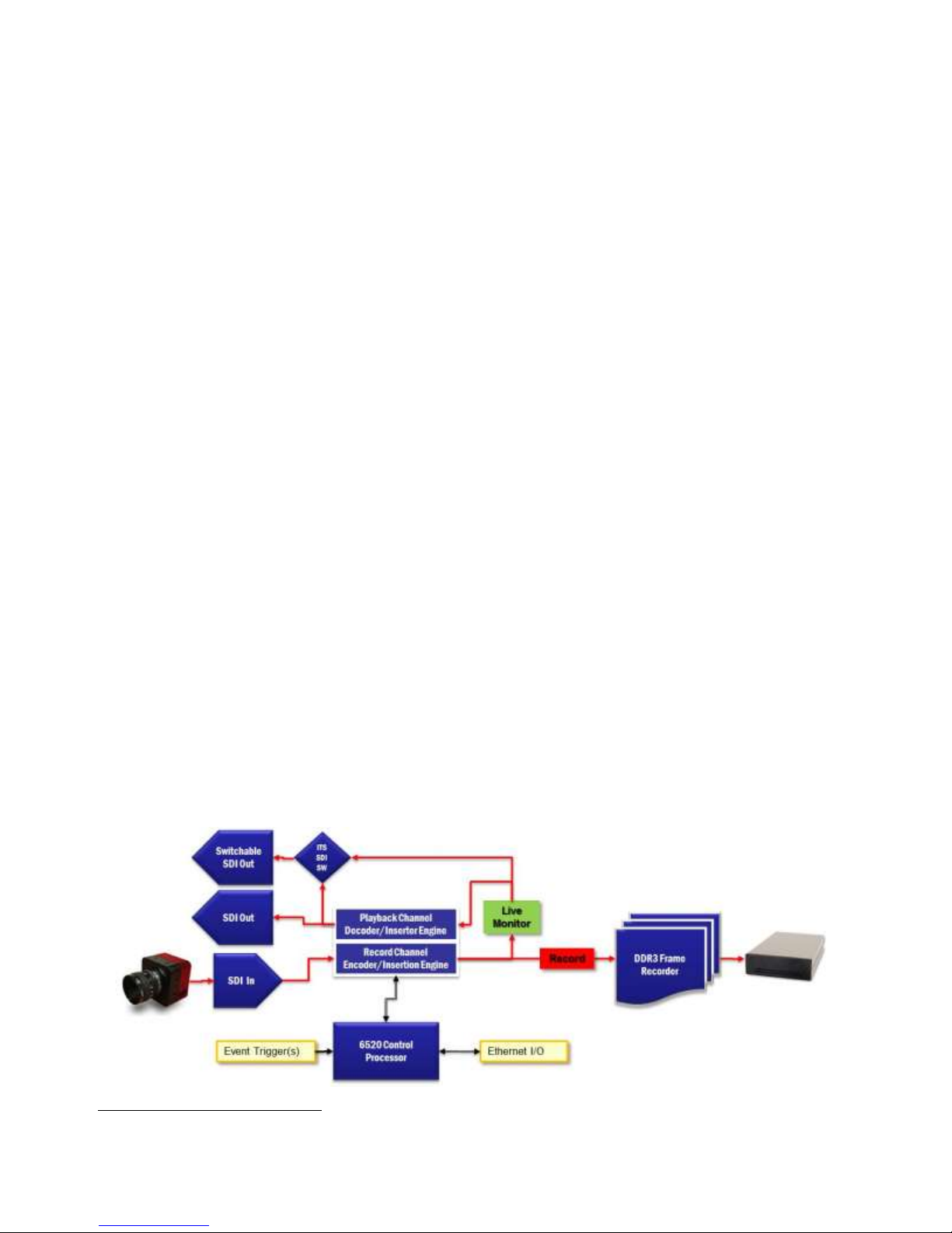
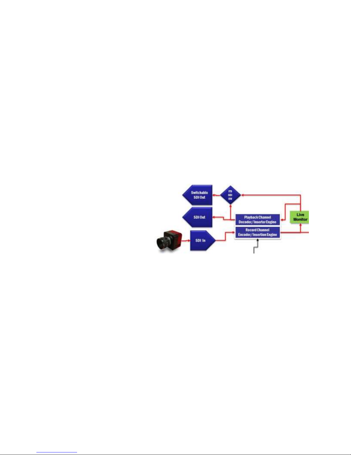
The block diagram below depicts the recorder signal flows in record mode.
Metadata functions are not supported when SMPTE 259M video is the source video or recorded clip.
6520 Inserter-Recorder Operation Manual Page 8
Page 16
The recorder contains two video processing engines.
1. The record channel includes the ability to overlay text, graphics (see 3.1.4 Movable
Crosshair and 3.1.5 Boresite Crosshair page 4), insert MISB 0605.3 Microsecond
Timestamps and insert up to two user defined SMPTE 291M type 02 KLV metadata packs
in accordance with SMPTE RP214.
2. The playback channel which includes the ability to overlay text, graphics (see 3.1.4
Movable Crosshair and 3.1.5 Boresite Crosshair page 4), decode and overlay MISB 0605.3
Microsecond Timestamps and decode and overlay selected fields of up to two user defined
SMPTE 291M type 02 KLV metadata packs in accordance with SMPTE RP214. The
playback engine can also extract the KLV metadata packs and stream the data to the
Ethernet port frame-by-frame in real time.
There are two HD-SDI outputs (BNC) from the recorder. One output is fixed and always presents
the output of the playback channel. The second output is switched.
The switched output may present a duplicate of the playback channel, or may present the input to
the playback channel. The switched output may then be used to distribute the “clean” recorded
video or a duplicate of the playback channel output which may contain decoded and overlaid
metadata, time stamps and contemporaneous information input by the user during playback only.
In record mode, the two outputs function as a live monitor that are connected to the output of the
record channel in parallel to the DDR3 or SSD. The live monitor video is delayed only 8µs from
the input SDI video being received by the 6520.
The switched output video may be set to see what is being recorded only (clean video), while the
unswitched may be decoding and overlaying metadata, timestamps and contemporaneously
overlaid massages initiated by the operator during record operations.
Clips may be recorded to DDR3 only, recorded to DDR3 then saved to SSD or recorded directly to
SSD. The clip length that may be recorded is limited by the video format and total capacity of the
DDR3 and the unused capacity of the SSD. Capacity of the SSD may be freed by erasing one or
more of the previously recorded clips.
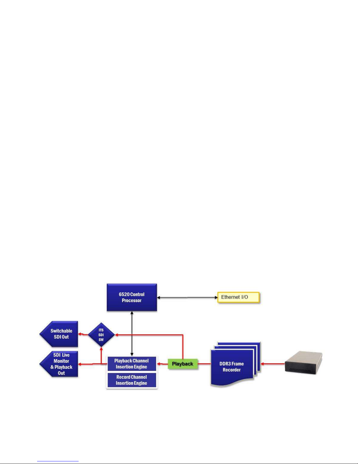
The block diagram below depicts the 6520 in playback mode.
In playback mode recorded data may be retrieved from the DDR3 (event clips) or from the SSD
where the DDR3 acts as a buffer.
6520 Inserter-Recorder Operation Manual Page 9
Page 17

The playback channel Insertion Engine may then be used to overlay information
contemporaneously or decode and overlay fields of the metadata stored in the VANC space
frame-to-frame in KLV packs.
The switched SDI output may present either the output from the playback channel or the raw video
output from the DDR3/SSD source.
3.3.1 Event Record (ER)
There are two event record (ER) modes; record the event only to the DDR3 and record the
pre-event to DDR3 and post-event to SSD.
ER mode stores incoming video to the DDR3 memory space. The operator sets the record length
in total frames. The frame count may be translated to time when the format and frame rate is
known (see 3.4.4.1 DDR3 page 18 for maximum clip lengths).
The DDR3 memory space may be divided into equal partitions. For example, the 16GB DDR3
could be divided in two 8 GB partitions. Partitioned this way, the 6520 could record 2,700 frames
of720p or 1,450 frames of 1080p video.
In ER mode, the partitions can be set to “Ping-Pong”. That is, one partition may be writing to SSD
(saving the previously recorded clip) while the other is recording a new clip. The save time would
slightly less than the duration of the clip record time.
In the rack mount package or when using the remote panel, ER mode is indicated by an
illuminated EVNT button. In this configuration, one partition is active and the other is
either writing to SSD (saving a clip) or idle in standby mode. The active partition will
continuously record frames in circular fashion emulating a loop recorder.
Recording may be stopped immediately at any time by pressing STOP or sending a stop
command (serial, GUI, or webserver).
Once any ER mode is set, RECORD arms the event trigger preparing the system to save the
pre-event frames and capture post-event frames.
Refer to Appendix D: Calculating Frame Capacities for assistance in determining frame
capacities, recording times and setting the stop delay for event recording.
ER mode may be paused by pressing play (available to restart as previously programmed) or
cancelled by sending a hard stop with zero delay. This returns the recorder to a standard clip
record mode.
3.3.1.1 ER: DDR3 Only
When recording the event only to DDR3, the clip length is limited by the total DDR3 capacity of
the whether there are one or two partitions of the DDR3 specified. Any clip currently stored in the
DDR3 may later be saved to SSD on command (serial, Ethernet, webserver or GUI).
When RECORD is initiated in this mode, the DDR3 records n-frames (specified as loop length by
the user) in circular mode until a STOP is initiated or an event trigger is received.
When the Event ( ) button is tapped or an event trigger is received (discrete, serial, webserver
or GUI) the 6520 continues recording video until the number of post event frames set by the user is
captured. This is effectively a delayed stop.
A delayed stop is a feature that enables an event to be captured to a clip. An event clip records
video before and after the event itself. The delayed stop setting, then, permits the operator to
6520 Inserter-Recorder Operation Manual Page 10
Page 18

instruct the recorder to continuously record (to DDR3) at the set loop length. When an event
trigger is received, the recorder will record the number of frames specified after the trigger,
overwriting the oldest previously recorded frames. The result is a clip containing Loop Length;
Delay Stop Frames of pre-trigger video; and Delay Stop Frames of post-trigger video. This is
accomplished with a single event trigger command, discrete, serial, webserver, GUI or manual
event input. The delayed parameters are set by commands sent via command, webserver, or GUI.
A delayed stop is created when the operator enters a number of frames to be recorded after an
event is triggered (either by discrete input or Ethernet command or tapping the EVNT, , button).
The value entered may be 1% to 99% of the total loop length. If desired the loop length and
percent delay may be saved as defaults that will survive power cycling.
While in a delayed stop (Event Stop) the RECORD button (if present) will flash.
If the ER mode is not in Ping-Pong, the 6520 enter STOP mode.
If there are two DDR3 partitions and the 6520 is in Ping-Pong, it will begin DDR3>SSD save
operations for the clip just captured, return to event record mode with event input armed using the
idle partition. In Ping-Pong, event clips may be captured sequentially until the capacity of the
SSD is exhausted. Events may be as close as the loop length. For example, if a 1080p/60 30
second loop is specified, 90 events can be captured to a single 1 TB SSD where the system only
needs to receive a trigger for each event. The Ping-Pong and save operations are all automated.
3.3.1.2 ER: DDR3 & SSD (only with SSD option)
In this mode, the DDR3 records in a loop using the user set loop length until an event is triggered.
When an event is triggered, recording continues to the SSD. There is no delayed stop. Recording
will continue until a STOP is received (button, serial, webserver or GUI) or until the capacity of
the SSD is exhausted. While all of the video is captured to the 6520 memories, SSD save of the
last n seconds (loop length time) of video must complete before the system enters stop mode.
The resulting clip starts with the number of pre-event frames captures (the length of the loop) and
the number of post event frames.
For example, a 1 partition 32GB DDR3 loop can be set to 5,400 frames of 1080p video. If the
frame rate is 60 FPS, then the prevent sequence is 5400/60=90 seconds. The post event clip can be
as long as the capacity of the SSD less 90 seconds assuming a “fresh and formatted” SSD is
present. The event captured could then be 44 minutes of uncompressed video, 1.5 minutes before
the event and 43.5 minutes after.
. This mode requires that the DDR3 be configured to one (1) partition. DDR3 Ping-Pong is NOT
permitted in the ER mode
3.3.1.3 Rack Mount/Remote Control ER Operation
In the rack mount or when using the remote panel an event can be manually indicated by tapping
the EVNT button. While still recording (delayed stop) this button will flash until the
recording of the loop post-event is complete. The EVNT button will return to solid
illumination on completion of the loop. If there are two DDR3 partitions set (must be set
by command, GUI or webserver) then the system is in loop record mode and is ready to accept
another manual, discrete or Ethernet event command.
If the 6520 is in DDR>SSD event record mode, when STOP is pressed, the Record Button will
begin to flash until the final seconds of the video resident in the DDR is saved to SSD.
6520 Inserter-Recorder Operation Manual Page 11
Page 19

4
5
In the rack mount package or when using the remote panel, a hard stop is initiated by
tapping the STOP button. When the STOP button is pressed, the EVNT button will no
longer be illuminated indicating that the recorder is no longer in event record mode.
To start a recording (either event or start-stop manually), a RECORD plus a number from
00 (record in new unused space) or xx (overwrite an existing clip) is commanded. In the
RM package or with the remote control panel, tap REC. If record operation is meant to be
event record, stop delay is set to a value greater than zero BEFORE starting a record operation.
In the RM package or when the Remote Control Panel is used with the shelf mount package, a
default event loop may be created. The default sets the loop to the size of the current DDR3
partition. The delayed stop is set in the middle of the loop. The default event clip holds
equal video times before and after the event. The default event loop is created by holding
the EVNT button for two4 seconds or more.
DDR3/SSD event record mode must be set up using the GUI, webserver or command set.
3.3.2 Continuous Record (Only with SSD option)
Continuous record (CR) uses the DDR3 memory as a dynamic buffer for the incoming video
which in turns saves the video frame by frame to the SSD. The dynamic buffer function
compensates for periodic leveling functions and continuous write delays experienced with SSDs.
This DDR3 buffer prevents frame loss during recording.
In CR mode, one can record a video clip that is the full capacity of the SSD (see 3.6 Solid State
Disk (Option) page 19 for capacities and typical record lengths). If a clip currently resides on the
SSD, one may record a new clip to the limit of the unused capacity.
If the clip value specified by RECORD ##5 is zero (00) the 6520 will record the new clip in the
next available SSD space. If an existing clip number is specified (non-zero value), the clip
identified by the clip number will be overwritten and the previous video recording will be lost. If
the new recording is longer than the clip being overwritten, recording will continue in unrecorded
space up to the unrecorded capacity of the selected media or until a stop is initiated.
3.3.3 Continuous Record with RM or Remote Panel
In the RM package or using the remote control panel, continuous record is initiated by
setting the system to save to SSD (>SSD). Tap this button. When illuminated, the 6520
will record clips directly to the SSD. From this panel control, a new clip will be written
using the next clip number and will record when REC is tapped until the end of SSD capacity or
until STOP is tapped. To return to DDR3 record (default) tap >SSD until this button is no longer
illuminated. When STOP is tapped, the REC button will flash until any frames remaining in the
DDR3 buffer are saved to the SSD.
3.3.4 Save DDR3 Clips to SSD automatically (requires SSD option)
Two seconds is the factory default, however it is user programmable from 0.5 seconds to 5.0 seconds in 0.1 second
increments.
The clip number referenced here is NOT a part of the clip file name. It is an index reference used by the 6520 to
locate files of the user‟s choosing. The clip file name associated with this number may change any time a clip is
erased or a clip is overwritten by a new clip.
6520 Inserter-Recorder Operation Manual Page 12
Page 20

Either by Ethernet command, RM front panel or remote control panel, the 6520 may be set
to automatically save a clip recorded to DDR3 to SSD. When so configured, when either a
stop after record or a delayed stop (ER mode) occurs, the recorder will immediately begin to
save the clip to SSD using the next clip number. If the SSD has insufficient capacity, all complete
frames that may be saved will be saved. In this instance, an incomplete clip will be saved and will
be indicated in the RM and remote control panel by flashing the >SSD button and in the
shelf mount package flashing the SSD LED.
This condition will remain until power is removed, a command is sent to take the recorder
out of auto-save mode, or the >SSD button is depressed and held until the button is no longer
illuminated.
3.3.5 SSD Operation
When the SSD option is purchased, a door is found on the front panel that may be opened/secured
with a thumbscrew. The SSD is installed in a slot behind a protective door of the 6520. The door
has an integrated weather seal to minimize the introduction of contaminates into the SSD frame.
While there are no interlocks to prevent it, it is highly recommended that this door be closed and
secured at all times whether an SSD is installed or not. This is especially important when
operating the recorder at ambient temperatures over 40ºC.
When the door is open, a slot is available to insert the SSD. It may only be inserted one way. If it
is attempted to insert it upside down, it will not mount. Do not force it.
When inserting and SSD, open the door, slide the SSD in place and fully seat it. Use the supplied
key to lock the SSD in place. The SSD will not operate unless it is locked in place. The lock
secures the SSD and connects power to the drive installed internally in the SSD carrier.
To remove the SSD, open the door, unlock with the key and press the tab. The tab should extend
at first. Press it a second time and it should disengage the SSD from the frame for easy removal.
Close and secure the 6520 door immediately to reduce the introduction of contaminates to the
internal elements of the system and ensure the system cooling operates efficiently.
SSD option information is found in 3.6 Solid State Disk (Option) page 19.
When inserted and locked, the 6520 will access the SSD to determine the status (formatted,
unformatted, presence of previously recorded clips). The operator may choose to
1. format the SSD,
2. erase a previously recorded clip,
3. erase all previously recorded clips,
4. play a previously recorded clip
5. If properly formatted, begin record or playback operations as appropriate.
6. Clear the SSD
3.4 Status Screen
The 6520 will compose a 720p/60 frame that may be viewed at the Playback SDI output port. On
power up, this screen (when an attached SDI display has synchronized with the SDI stream) will
present initialization information as shown below.
6520 Inserter-Recorder Operation Manual Page 13
Page 21

6520xy-32CS
Firmware Versions
Main
Video
GPS
IP Data
192.168.150.92
00023
255.255.255.0
192.168.150.100
Serial Baud
9600
DDR
Present
Capacity
32GB
SSD
Present
Capacity
899GB
This status screen content only appears at power up or after a reboot.
6520 Inserter-Recorder Operation Manual Page 14
Page 22

Clip
Time Stamp/SN
Frames
Format
D01
Clip Recorded
5280
720p/60
D02
IDLE
0
S01
001D2015270102427092
18000
720p/60
S02*
001D2015269064733005
27000
720p/60
S03
001D2015260174911643
17100
1080p/30
Available DDR3 Capacity 16GB
Available SSD Capacity 712GB
Time Reference: GPS: Locked: 12 Sat
NTP disabled IRIG: not present
After any command is received, the status screen formed will contain operating information as
shown below also described as the clip list (see 3.4.1 Clip List for more information).
This screen, when enabled, will remain while in stop mode. This screen may be disabled at
any time via command, webserver, GUI or by pressing and holding the RM/Remote Control
STOP button (flashes when the status screen is enabled). When the status screen is disabled,
the SDI output channel will revert to live video (echoes the input video).
When Record (any mode) or play (any speed) is initiated, live or playback video will be
present at the output part.
When the Status Screen is disabled and the recorder is in STOP mode, live video if any is
present at both SDI outputs.
3.4.1 Clip List
The clip list is a facility of the 6520 to help an operator identify, play, delete, offload and record
clips. The clip list may display video saved to DDR3 (clip D0x), SSD (Sxx) or both.
When an SSD is inserted into the 6520 and locked into place, the 6520 examines the SSD content.
If the 6520 is connected to and SDI monitor, and the Status Screen is enabled, it will display the
status of the inserted SSD.
Status may be N/A (not connected), Unformatted, Formatted and capacity in GB or a list of clips
will be presented.
Each clip is assigned a name (see SSD File Names, page 19, for details) by the 6520 at the time
recording (or saving) to the SSD is initiated. DDR clips have no clip name until saved to the SSD.
Each record displays the number of frames in the clip and the video format and frame rate of the
clip. The clip length in seconds can be determined by dividing the frame count by the frame rate.
The Status Screen may be enabled by an Ethernet command or when using the RM package or
remote control panel by pressing and holding for two seconds the STOP button, . (flashes when
enabled). The Status screen, a 720p/60 video format) only appears when the recorder is in STOP
mode.
6520 Inserter-Recorder Operation Manual Page 15
Page 23
The clip list may also be retrieved anytime remotely via the Ethernet port with the appropriate
command (See 7.7 Recorder Controls via Keyboard).
In the example above clip numbers preceded by D indicated clips present in the DDR3. IDLE
indicates that the DDR3 is divided into two partitions and the second partition is empty.
Clip numbers preceded by S are present in the SSD.
The clip having the “*” symbol is that which is selected for playback, overwrite or erasure if so
commanded (also known as the CURRENT CLIP).
At the bottom of the Status Screen the available capacity (unrecorded) of the DDR3 and SSD are
shown. Frame count capacity and record length in time cannot be calculated at this point since
such parameters can only be determined when the source video is known to the system.
3.4.2 Live Monitor
The live monitor is an SDI output available at both the switched and unswitched outputs. The live
video output appears in STOP mode when the Status Screen is disabled or during any RECORD
operation. Live Monitor is a real time view of what is at the recorder input with latency from
camera input to this output of less than 8µs.
Since the playback channel has full overlay capabilities, crosshairs and text messages may be
inserted on this video output without
affecting the video actually being
recorded. Information to assist an
operator during the live event that is
not pertinent to later event analysis
may be presented during with the live
monitor.
If metadata is being inserted into the
recording, the metadata may be
recorded by the playback channel and all or part of this data may also be overlaid in the Live
Monitor SDI signal without affecting the video being recorded. Therefore, the recorded video
may be totally free of overlay while the live monitor video may contain sensor data and other
messages to assist an operator during the recording interval.
Both SDI outputs are active during live monitor. The switchable SDI out may be set to monitor
the actual video input to the recorder storage device (DDR3 or SSD) in order to view the video
being recorded as it is recorded. If no features of overlay are used in the playback channel, the
unswitched output would reflect this same imagery. There is a time difference between the
switched (sooner) and the unswitched (later) outputs of 4µsec. More importantly,
contemporaneous text messages may be inserted into the unswitched channel to direct or assist an
observer/operator during the live recording. This channel may also contain overlay derived from
KLV metadata inserted by the record channel. None of the overlay inserted by the playback
channel would be recorded.
3.4.3 Playback
The 6520 recorder will playback recordings at SDI ports at full motion video frame rates. The
Play command is initiated with a clip number (see 3.4.1 Clip List page 15 for clip number
conventions) to be played.
Playback receives SMPTE 125 (480/576) SMPTE 296 (720) or SMPTE 274 (1080) video data
6520 Inserter-Recorder Operation Manual Page 16
Page 24
from the SSD or DDR3, may decode and overlay timestamps and data recorded in the metadata
frame to frame and even add crosshair graphics and other text that does not appear in the recorded
imagery. The playback channel then converts this data to SMPTE 259M, 292M or 424M SDI
video stream as appropriate.
The playback frame rate (FR) is user variable. Playback may be at output 1/32FR to 1xFR in 32
steps (slow motion) or 1xFR to 32xFR in 32 steps (search). Speeds greater than the original video
FR are achieve by skipping frames to simulate the FR indicated.
Both the switchable and unswitched SDI outputs are active during playback The switchable output
may be set to present the video as recorded while the unswitched output will present the recorded
video plus any overlay resulting from contemporaneous messages input by an operator or data
extracted from existent metadata recorded (e.g. timestamps, user defined KLV fields of data).
3.4.3.1 Playback using the Rack Mount or Remote Control Panel
Manually an operator can play any clip previously recorded. When the >SSD button is not
illuminated the system will not only record to DDR3, but will play from DDR3. When this
button is illuminated, playback will originate from the SSD. This source may be changed
either by Ethernet command or by pressing and holding this button until the status changes as
indicated by the illumination of the button.
Play may be initiated in either the forward or reverse direction from stop by pressing the >
or < PLY button. Tapping this button will single step (frame-by-frame) playback each time
it is tapped. Holding the button for two seconds will place the recorder in continuous
playback mode at 1xFR. The actuated button will illuminate solid indicating the mode and
direction of playback. Once in continuous playback mode, either button may be tapped to increase
or decrease playback speed.
In order to slow the playback speed tap the < PLY button regardless of the indicated direction.
Each tap will decrement the speed by 1/32FR. In order to increase the speed tap the > PLY button
the speed will increase. Speed changes above 1xFR follow an exponential curve between 1/xFR
and 32FR. When either in slow or fast playback, the corresponding direction button (> or <) will
flash. When in slow-motion, the flash will be approximately 1/second, when at speeds above
1xFR, the flash will be at approximately 2/second. When speed is returned to 1x, the
corresponding direction button will illuminate continuously.
Pressing and holding either play button again (after play mode has been initiated) will take the
recorder out of play mode and return it to single step mode. When this is accomplished, the video
will be stopped on a frame and displayed PLAY mode zero speed. Tapping either direction button
will advance or decrement one frame in the recorded clip.
Stop will take the recorder out of PLAY mode to STOP mode, however the last displayed frame
will remain in the SDI output unless the Status Screen is enabled.
Tapping rewind (RWND) will set the clip to the first frame of the active clip. Playing
from this point will begin at the beginning of this clip.
3.4.3.2 Selecting previously recorded clips
The operator may decrement from the CURRENT CLIP by pressing and holding the RWND and
tapping < PLY button. While moving to this previously recorded clip, the RWND button will
flash. When ready to play, the recorder will display the first frame of the newly selected clip and
will be set to PLAY forward (>) speed zero and the RWND button will extinguish.
6520 Inserter-Recorder Operation Manual Page 17
Page 25

The operator may advance through the clip list by pressing and holding the RWND and tapping
PLY > button. While moving to the next recorded clip, the RWND button will flash. When ready
to play, the recorder will display the first frame of the clip and will be set to PLAY forward (>)
speed zero and the RWND button will extinguish.
These actions may be repeated until the clip desired to playback is selected (can be viewed on the
green status screen).
If it is desired to force the system to select the LAST recorded clip for playback, press and hold
BOTH the STOP and RWND button.
3.4.4 Memory Clear
Functions built into the 6520 will execute procedures compliant with per DOD 5202.22-M to clear
the non-volatile (SSD) memory and volatile (DDR3) memory of all video and metadata previously
recorded. As stated I DOD 5220.22-M,
Clearing. The removal of information from the media to facilitate continued use and to
prevent the AIS system from recovering previously stored data. However, the data may be
recovered using laboratory techniques. Overwriting and degaussing are acceptable methods
of clearing media.”
Neither the SSD storage medium nor the DDR3 are magnetic devices, thus degaussing is not
applicable.
Method C overwrites all addressable locations with a single character.
Method H performs a full SSD erase as per manufacturer‟s data sheets.
3.4.4.1 DDR3 CLEAR
When a clear is initiated for the DDR3 method C (Overwrite all addressable locations with a single
character, then remove power) defined by DOD 5220.22-M, in Exhibit B, DSS Clearing and
Sanitization Matrix of June 28, 2007 , is executed and applied to the entirety of the DDR3 three
times. After this operation, no event partitions will remain. In the shelf mount versions of the 6520
clear status is also indicated on the front panel by flashing the REC @ twice per second while clear
processing is proceeding followed by STOP.
In the rack mount versions of the 6520 status will appear in the LCD indicating DDR3
CLEARING in the status message until complete.
Method C also requires the removal of power to the DDR3. This step will be left to the operator.
3.4.4.2 SSD CLEAR
When a clear is initiated for and installed SSD module method H (Perform a full chip erase as per
manufacturer’s data sheets.) defined by DOD 5202.22-M in Exhibit B, DSS Clearing and Sanitization
Matrix of June 28, 2007, is executed and applied to the entirety of the SSD. After this operation,
the SSD is erased and must be reformatted in the system if to be used for clip recording again.
In the shelf mount versions of the 6520 SSD cleaning will be indicated by flashing the SSD LED
once per second while flashing the REC LED in a manner to indicate the step.
Step C will flash REC once then dark for 2 seconds, Step His indicated by flashing REC
continuously until complete. When complete REC is dark and the SSD LED is illuminated solid.
In rack mount versions the clean status is displayed in the LCD as:
6520 Inserter-Recorder Operation Manual Page 18
Page 26
IT Model
Capacity
(bytes)
Recording Length Frames/Time (sec)
480i/60
720p/60
1080p/30 or
1080i/60
1080p/60
6520xx-16
16GB
13K/420
5.5K/95
2.8K/96
2.8K/48
6520xx-32
32GB
26K/840
11K/180
5.5K/180
5.5K/90
IT Model
Capacity
(bytes)
Recording Length Frames/Time (mins)
480i/60
720p/60
1080p/30 or
1080i/60
1080p/60
6520SSD-1000
1,000 MB
810K/450
344K/95
172K/95
172K/47
CLEAR H until complete.
Do not attempt to remove and SSD during clearing. If removed during this operation, the clear
will not be valid and the SSD will be may be unusable.
Clearing the SSD may take considerable time; in excess of 40 minutes for 1 TB.
If an SDI monitor is connected to the unswitched SDI output, a CLEAR status is provided the
Status Screen if enabled. The status declares the step in progress (e.g. C or F) and the progress of
the step (xx% Complete).
3.5 DDR3 Options
The DDR3 volatile memory is a high performance DIMM dynamic RAM. This factory installed
DIMM is available in capacities of 16GB and 32GB. The DDR3 is configured as a buffer to the
SSD when in Continuous Record mode or as a clip recorder memory when in (ER) mode. Clip
record capabilities are listed below.
3.6 Solid State Disk (Option)
This option must be purchased at the time of order. It is not field upgradable.
The SSD is housed in a CRU® Dataport® 25 enclosure (Part number 8511-5009-9500). This
enclosure houses one (1) or two (2) qualified SSDs. The SSDs installed depend on the capacity
purchased for this option. SSDs installed are tested and qualified to support the read and write
rates necessary to continuously record and playback up to 3G 1080p/60 (SMPTE 424M) HD-SDI
video with no frame loss or freeze frames at playback.
A list SSDs ITS has qualified as a part number by manufacturer will be available on request.
However, unless screened by ITS, no warranty is given or implied that an independently purchased
SSD will meet the 6520 system requirements even if the specific part number is on our qualified
list.
SSD capacities and ITS part numbers available are:
RECORD TIMES FOR THESE CAPACITIES ARE VARIABLE DEPENDING ON THE
RECORDED AND THE FRAME RATE (SEE
Appendix D: Calculating Frame Capacities) for assistance in estimating frame capacities and
recording times).
3.6.1 SSD File Names
Clip file names are constructed using a system serial number in HEX followed by
6520 Inserter-Recorder Operation Manual Page 19
Page 27

YYYYDDDHHMMSSsss. For example a recording from the serial number 00029 control board
(internal) in 2015 on the 271st day of the year at 1500 hours 31 minutes 58.100 seconds would
result in a clip name ASCII strong of 001D2015271153158100. This method provides traceability
to the recorded that captured the clip and the time. It also ensures that all file names generated by
any number of units would be unique. Also displayed is the number of frames in the clip, the
video format and frame rate. In order to conveniently select a clip for play, record or deletion,
each clip will be numbered starting from one. The clip number is a temporary assignment that
may change after each record or delete operation. A simulated list is shown above.
3.6.2 Assembling your own SSD
In the event it is desired to independently purchase a SSD and install it in a CRU drive enclosure,
install the SSD in the bottom SATA slot.
At this writing only use SAMSUNG 850 PRO SSD, part number MZ-7KE1T0BW.
3.7 Ethernet Control/Status Interface Functions
The ITS Ethernet interface on the 6520 will initialize to TCP/IP listen mode at power up. In this
mode, the interface is available to make a connection to up to four (4) clients. The IP address,
port, subnet mask and gateway parameters are identical for each server/client connection (socket).
This interface auto-negotiates 10/100/1000 TCIP IPv4 connections.
The factory default values are 192.168.150.90: port 23; 255.255.255.255; 192.168.150.100.
3.7.1 Multi-Client Capability
When a connection is established (bound) a client/server channel is open where all information
(commands and status) will be unique to this bound link (on the computer side, a socket). Each
socket established will be tested by the 6520 using a keep alive test (see 3.7.2 IP Keep Alive page
20). If a connection is broken that particular socket will be closed at the server end up to 10
minutes after the last socket was opened. All other active sockets will remain open or available to
link to a client.
When a code down load is initiated on any socket, all remaining sockets will immediately
be closed by the 6520 server and will be unavailable for reconnect until the code upload
sequence is complete and the system reboots. After reboot it will automatically reconnect
to the socket that initiated the code upload.
This protocol protects the integrity of an upload and prevents other operators form intervening
during the sequence.
3.7.2 IP Keep Alive
In the event that the client suffers a disorderly shutdown, or the physical path between the client
and any router/switch between the controller and client fails, the 6520 will detect this event. The
6520 employs the TCP/IP keep-alive function to do so. This function sends an empty packet from
the server to the client periodically. When the path between the client and 6520 is complete and
the connection is still open at the client side, the client responds (in the background) with an
acknowledge packet. This tells the 6520 that the connection to the client for this socket is still
valid. The 6520 issues a TCP/IP keep alive packet after 60 seconds of connection inactivity for any
of the four client/server channels. If not acknowledge from the relevant client is received, the
6520 will wait 60 more seconds and try again. This will repeat three more times. If no
acknowledge is received from the relevant client after five (5) attempts, the 6520 automatically
closes its server side connection and returns to TCP/IP listen mode. This client socket becomes
6520 Inserter-Recorder Operation Manual Page 20
Page 28
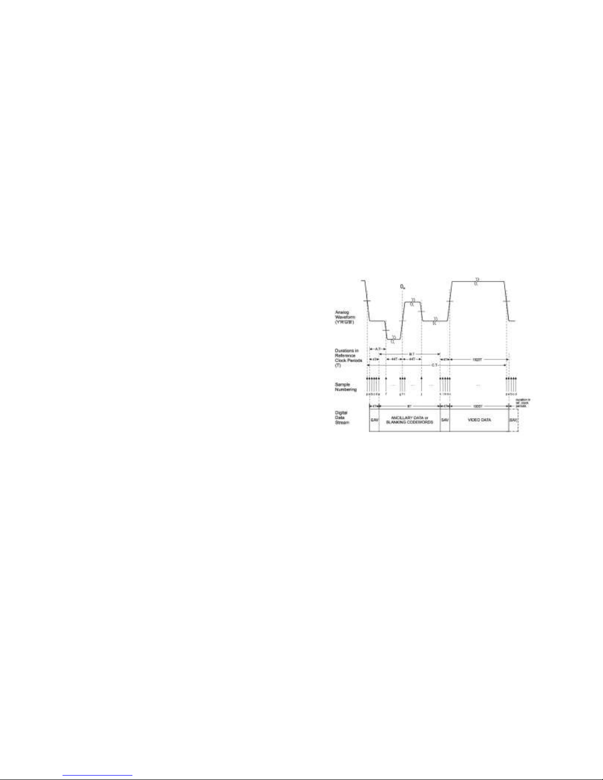
available reconnection.
3.7.3 UDP Discovery Capability
If UDP broadcast message, “ITS CLIENT REQUEST", directed to UDP port 1757 is sent over a
connected network, the 6520 will respond with its current TCP/IP address, gateway address,
subnet mask and MAC address. This message is sent to the requesting IP address and the IP
broadcast address of 255.255.255.255. This insures that discovery of all ITS equipment is
achieved across a network. The response returned on UDP port 1758 is:
MAC address (6 bytes)
IP address (4 bytes)
gateway address (4 bytes)
network address mask (4 bytes)
port number (2 bytes)
3.8 Camera Sync (CS Option)
The Camera Sync (CS) option is available for the 6520. This option must be selected at the time
of order as it is not a field upgradable feature.
The CS function generates TTL or tri-level sync (TLS)
signals that may be used to synchronize the picture
taking of a video source (e.g. camera) to a time
reference such as the optional GPS, IRIG B or NTP.
When using an NTSC HD-SDI video source (e.g.
60/1.001 frames per second), the sync will coincide
with the time mark within 1-µsec of the “one-second”
mark of reference clock every 1001 seconds.
The TLS vertical event is the 0H point of the HD-SDI
video stream as mapped by SMPTE 296M or 274M for
the appropriate video format. A representative TLS wave form is shown at the right. The TTL
sync generates a positive true leading edge pulse 384 µsec long that is phase locked to the time
reference in use by the 6520.
The CS function offers the ability to derive the sync rate based on the connected HD-SDI video
source (auto-sync) or set the frame rate by the operator to 23.97, 24, 25, 29.97, 30, 50, 59.94 or
60 Hz. The set value must match the frame rate of the video source for proper operation with the
connected video source.
The CS function includes a Time Reference Delay (TRD) that can shift the sync event relative to
the time reference by as much as 32 ms in 1-µsec increments. This facilitates alignment of picture
taking of cameras of two different technologies (e.g. visible light CMOS, CCD or IR).
This option also adds the capability to select on which event time is collected. Choices are the
EAV signature of the incoming HD-SDI video, the 0H point in the TLS or the leading edge of the
TTL sync.
Lastly, the CS option permits a user to add a ±20 ms (in 1-µsec increments) offset to the time
collected. The resultant time is recorded in the VANC Microsecond Timestamp pack and any time
overlay. This further enables calibration of picture taking time across a number of cameras and
sensor technologies.
6520 Inserter-Recorder Operation Manual Page 21
Page 29

Model
Height (inches)
Width (inches)
Depth (inches)
Weight (lbs)
6520Rx-nnyaa
3.75 (2U)
19
9
5.5
6520x-nnyaa
3.5
10.5
7.825
6.0
3.9 User Defined KLV pack
The KLV metadata write, read, extract features are standard in all models of the 6520.
The KL enables one to write/read up to two additional SMPTE 291M type 02 KLV (key-length-
value) data packets per frame. When written by the 6520 they are placed immediately after the
SMPTE KLV Microsecond Timestamp pack on line 9. Each of these option packs may carry up
to 235 bytes of user defined data. The data source may be the Ethernet input or data internal to the
6520 (e.g. lat/long/height, IP address, video resolution of the channel frame rate, etc.). The KLV
Software Toolkit is supplied free of charge (see KL Option Overview page 113). The software
toolkit contains data content authoring tools, GUIs to input test data and read output files.
With the use of the ITS authoring tool, KeyTemplate©, one can create up to 64 separate fields of
data of binary, ASCII, integer, decimal and floating point content. All of the data may be input via
the Ethernet port (the serial port is not fast enough to support full frame rates at full pack sizes) and
may be sourced from data available within the 6520 system or a merger of them both.
The 6520 may write, monitor or read the KLV option packs. The live monitor channel is one in
which the system is writing KLV packs and the data being written to the packs is overlaid (human
readable) on the video frame of the live monitor channel only. When reading packs, none, any or
all of the data may be decoded and displayed compliant with the formats specified by the user with
the KeyTemplate© authoring tool.
For complete details about the use and features of the KL option, please refer to Appendix F: KL
Software toolkit.
4.0 MECHANICAL CONFIGURATION
The 6520 may be ordered in shelf mount or rack mount versions either AC or DC powered. The
dimensions are as shown below:
Weight includes the SSD
R=rack mount. When omitted package is shelf mount
x = A is 115/240 VAC 50/60 Hz input power; x=D is 12-36 VDC input power
nn = DDR3 capacity, 16 = 16GB; 32=32GB
y = omitted includes and SSD. y=N does not include the SSD
aa = CS includes camera sync and the S3 option, omitted does not include CS
Add 0.5 pounds to each base for CS option
Subtract 1 pound when NO SSD option is included.
6520 Inserter-Recorder Operation Manual Page 22
SSD module is 0.5 pounds
Page 30
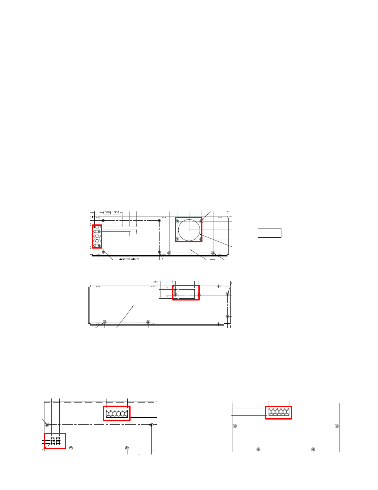
Front
Front
Front
Front
Inlet
Outlet
Inlet
4.1 Installation Information
4.1.1 Cooling
Both the shelf mount and rack mount versions require forced air cooling. An internal variable
speed blower is managed by the internal main processor. The main process monitors the chip
temperature and DDR temperature and adjusts blower speed to maintain these temperatures within
their respective operating temperature ranges.
Should the temperature exceed specifications, the 6520 will issue a warning via Ethernet, display a
warning on the webserver and flash STOP, PLAY and RECORD LEDs on the remote panel or
Shelf Mount Status Display. If the Status Screen is enabled, a CPU and DDR temperature report
will appear.
If operation continues while this warning is present, FPGA, DDR3 or power supply failure may
result.
During installation do not block the air ingress and egress ports. Any blocking surfaces must be no
less than 1 inch from these ports to ensure proper cooling. Inlet air temperature may not exceed
50ºC.
4.1.2 Rack Mount
The air outlets (two) are shown. They are on the left side of the unit when looking from the front
panel.
The air ingress is on the right side as seen from the front panel.
4.1.3 Shelf Mount
The air inlets (two) are on the left side of the unit as seen from the front (shown below). The air
6520 Inserter-Recorder Operation Manual Page 23
Page 31
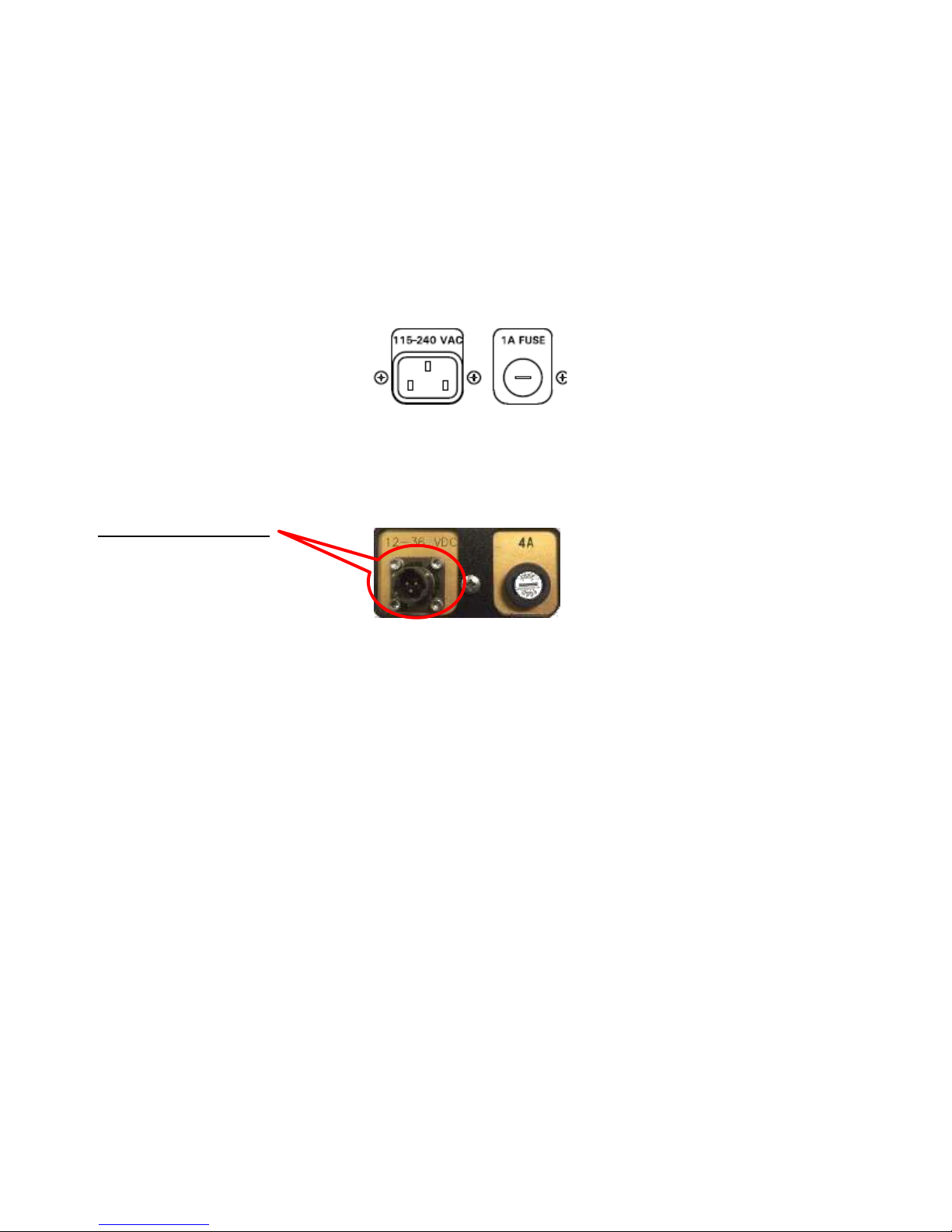
outlet is on the right side as seen from the front also shown below
When mounting the shelf mount unit, secure to a metal surface that could act as a “cold plate”.
This mounting strategy will add significant conduction cooling to the system enhancing the ability
to operate in 50ºC ambient environments. This is especially important with units having
32 GB DDR3 memory installed.
4.1.4 AC Power
Either the rack mount or shelf mount units may be ordered as AC powered. In that event, the rear
surface power input will appear as shown below.
The system is supplied with a standard IEC US line cord.
4.1.5 DC Power
Either the rack mount or shelf mount units may be ordered as DC powered. In that event, the rear
surface power input will appear as shown below.
PT02A8-4P Connector
Pin A = 12-36 VDC
Pin B = 12-36 VDC return
Pin C = Chassis
Pin D= n/u
6520 Inserter-Recorder Operation Manual Page 24
Page 32
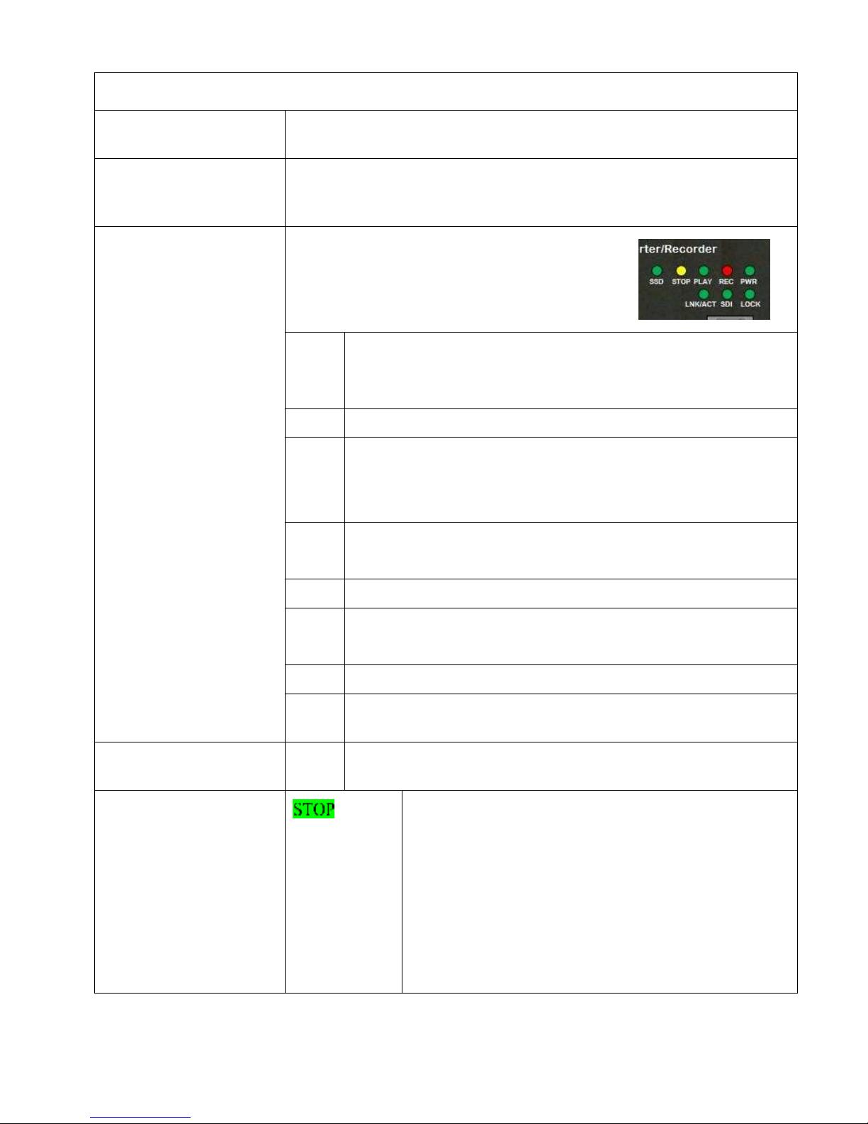
5.0 CONTROLS, INDICATORS, AND CONNECTORS
5.1 Power ON/OFF
Toggle switch / indicator: Controls power input. Indicator is illuminated
when power is on.
5.2 LC Display
R Option Only
Eighty character LC display: Dual row, forty character/line alpha-numeric
LCD supertwist display with LED backlight. Displays Time and Status
including: operation mode and time reference status
5.3 Shelf Mount
Status Display
The shelf mount unit provides an array of status
LEDs to indication various operation conditions
of the recorder.
SSD
On continuous when a direct record or DDR/SSD event mode
or event mode with auto-save is selected.
On flashing during save operation or playback from SSD.
STOP
Illuminated when in stop mode
PLAY
On Continuous in playback at 1X speed.
On flashing “fast” when in playback at greater than 1X.
On flashing “slow” when in playback at less than 1X.
REC
On continuous in any record mode (event or continuous).
On flashing during delayed stop (event mode).
PWR
On continuous while the AC or DC power supply is energized.
LNK/
ACT
On continuous when connected to Ethernet.
On flashing when data is received or sent by the recorder.
SDI
On continuous when any valid SDI video stream is present.
LOCK
On continuous when locked to GPS, IRIG (external) or NTP
(NTP not yet implemented).
ALL
All LEDs flash once per second when an over temperature
condition is detected.
5.4 Control Buttons
Rack Mount (RM) and
Remote Control Panel
only
Tap; stops recording or playback immediately. This
action also enables the PLY (> <) and SAVE buttons.
Also enabled is the ability to set the system in ER
mode, auto SAVE to SSD and RWND and RWND clip
select functions.
HOLD: Initiates display of the green status screen at
the unswitched SDI video output port.
When the status screen is activated, the STOP button
flashes when the recorder is in stop mode.
6520 Inserter-Recorder Operation Manual Page 25
Page 33

5.0 CONTROLS, INDICATORS, AND CONNECTORS
<PLY>
Tap > (play forward) from STOP advances SDI output
to next frame. Tap < (play reverse) from STOP to
display the previous frame.
HOLD: sets recorder in continuous playback mode in
the direction set by the button held. Once in playback
mode {either > or < button illuminated continuously at
first} tapping either button will increase (>) or
decrease (<) the playback speed. The current direction
button will flash fast indicating that the playback speed
is greater than a 1X. It will flash slowly to indicate
when less than a 1X speed is selected. When 1x is
reached, the direction button will return to continuous
illumination.
Press and hold either PLY button to return to single
step mode.
Press STOP to exit play mode.
The PLY buttons (> or <) are inactive until the unit is
first set to STOP.
Press either PLY button (> or <) from RECORD mode
and recording immediately stops recording the clip.
The CURRENT clip becomes that which was just
recorded and the recorder displays the first frame of
that clip. The mode becomes PLAY > at speed zero.
You may not enter any PLY mode from RECORD
while a save to SSD is in progress.
RWND
Tap: from STOP, will rewind to the beginning of the
current clip and stop playback. The recorder mode is
PLAY forward at speed zero
HOLD and tap > from STOP will advance to the next
clip from the selected source (SSD or DDR) and will
display the first frame of this clip on the SDI output.
HOLD and tap < from STOP, move to the previous
clip from the selected source (SSD or DDR) and will
display the first frame of this clip on the SDI.
In either case, the clip selected becomes the
CURRENT CLIP. The recorder mode becomes PLAY
forward at zero speed.
6520 Inserter-Recorder Operation Manual Page 26
Page 34

5.0 CONTROLS, INDICATORS, AND CONNECTORS
REC
Tap: from STOP initiates record on the currently
selected recording destination (DDR3 or SSD).
Recording will continue until:
1. STOP is tapped
2. EVNT is tapped while in ER mode. Record
will continue after EVNT is tapped until the
number of post event frames are recorded as set
by the user. The REC button will flash during
the delayed stop period indicating a stop is
pending.
3. If the end of capacity is reached for the record
destination REC flashes and recording stops.
The recorder is set to STOP mode. The REC
continues to flash until tapped (acknowledged)
or a command from the webserver or GUI has
the effect of acknowledging the full condition.
If the record destination is DDR3 and the 6520
is in ER mode, video is recorded in a loop
continuously. Therefore, no end of capacity
occurs in this mode.
Any new REC starts a new clip. There is no ability to
add more video to a previously recorded clip.
EVNT
Tap: Manual annunciation of an event. When the
recorder is set to ER mode, tapping this button will
begin the delayed stop. The value of the delayed stop
is either the default (1/2 of the DDR3 partition) or that
value set by the webserver, GUI or command. The
default value may be changed with the webserver, GUI
or command.
HOLD: From STOP sets the recorder in ER mode
using the current default delay and the current DDR3
partition settings.
>SSD
Tap: From STOP, toggles between recording to DDR3
and SSD. The button is illuminated when recording to
SSD. The default at power up is to record to DDR3.
6520 Inserter-Recorder Operation Manual Page 27
Page 35

5.0 CONTROLS, INDICATORS, AND CONNECTORS
SAVE
Tap: Only active from STOP. Will save the last clip
recorded in the current partition of the DDR3 to SSD.
The clip will be assigned a file name as described in
paragraph 3.6.1 SSD File Names page 19.
If the SSD is full, the button will indicate so by
flashing. It will remain in this condition until room is
made (e.g. deleting clips) or a new formatted SSD with
available capacity is inserted.
If insufficient space is available on the SSD, all full
frames of the clip that can be saved will be saved. In
this instance the button will be illuminated flashing to
indicate an incomplete save and that the SSD is full.
HOLD: Sets the 6520 to automatically save DDR3
clips to SSD. When set as such, the button is
illuminated continuously. In ER mode and after the
delayed stop has occurred, the system will transfer the
clip using the next clip number to the SSD. If the
DDR3 is partitioned, the next partition will be in loop
record mode while the previously recorded DDR3 clip
is being saved to the SSD.
If the recorder DDR is set to two partitions, autosave
mode and ping-pong, event recording can continue
until the SSD is full.
If the SSD no longer has available capacity, the button
will flash. If capacity is exhausted while transferring
the clip, all full frames that will fit in the space that
remained at the start of save operations will be saved
(incomplete clip). In ER mode, the partition from
which the clip was to be saved will not be marked as
ready to record and ping-pong mode will be
terminated.
Over Temp
When an over temperature condition (CPU or DDR
measured temperature exceeds 90ºC) is detected, all
buttons will flash once per second until the system
cools.
6520 Inserter-Recorder Operation Manual Page 28
Page 36

5.0 CONTROLS, INDICATORS, AND CONNECTORS
5.5 IRIG In
BNC Connector: Receives serial IRIG B time signal.
5.6 Ethernet
Standard RJ45 Ethernet connector: Provides interface up to four (4) host
computers via the Ethernet port.
5.7 Camera Sync
(Optional)
1 BNC connector for Tri-level sync output and 1 BNC for TTL sync
output.
5.8 Remote
RJ6 Connector: Interface for use with ITS 6520RCP recorder remote
control panel.
5.9 Discrete/Serial
DE9P Connector; This I/O connector provides an RS232
command/status port. All commands except metadata functions are
supported through this interface (Pins 2, 3, 5).
Pin Assignments
1) NC/Reserved
2) RxDA Serial RS-232 Rx data
3) TxDA Serial RS-232 Tx data
4) NC/Reserved
5) Ground
6) NC/Reserved
7) Current limited 5V
8) Discrete control input/Event Trigger (see below)
9) NC/Reserved
The discrete input is used to indicate that an event has occurred in
EVENT RECORD modes. The discrete is pulled up to 3.3V with a 10K
resistor and protected with a 1K (1/4W) resistor in series to Schottky
diodes between 3.3V and Ground to prevent damage from overvoltage
or reverse voltage. Input may be driven with 5V TTL, 3.3V LVTTL,
open-collector, or contact closure (threshold approximately 1.6V). If the
input is driven with voltages greater than 3.3V, the driver will source the
current through the protection 1K resistor. Continuous drive level
operation up to ±15V can safely be tolerated. Short duration pulses of <
100V can be tolerated (width <10 milliseconds).
5.10 Video In
One BNC Connector: Receives HD-SDI Video data stream. A green
LED adjacent to the connector illuminates when a valid SDI video
signal is applied.
5.11 Video Out
Two BNC Connectors: One permanently connected to the Playback
Channel Output and one switched between the Playback Channel Output
and Playback Channel Input. The output signal is an SD-SDI or
HD-SDI per SMPTE 259M, 292M, or 424M depending on what video is
being passed through (live monitor) or played back.
5.12 Power (AC)
3-pin IEC 60320 C-14 filtered connector: Factory installed option.
When selected, the DC power input is not available. Receives
detachable line cord (included)
6520 Inserter-Recorder Operation Manual Page 29
Page 37

5.0 CONTROLS, INDICATORS, AND CONNECTORS
5.13 Power (DC)
PT02A8-4P Connector: 12-36VDC external power. Amber LED Power
ON indicator. Factory installed option. When selected, the AC power
input is not available. An external AC power adapter is available.
See 4.1.5 DC Power page 24 for input pin assignments.
6520 Inserter-Recorder Operation Manual Page 30
Page 38

6.0 SPECIFICATIONS
6.1 Video In
Standard SD/HD/3G SDI digital video per SMPTE 259M, 292M and 424M.
Formats supported are:
480i at 29.97 FPS
576i at 25 FPS
720p at 25, 29.97, 30, 50, 59.94 and 60 FPS
1080i at 25, 29.97 and 30 FPS
1080p (3G) at 25, 29.97, 30, 50, 59.94 and 60 FPS
6.2 Video Out
Identical live input video or recorded video except with graphics, annotation and
metadata added as commanded.
One Video output is switchable to view the input to the playback channel or the
output of the playback channel. See Live Monitor on page 16 and Playback on
page 16 for details.
6.3 Timing Accuracy
When Locked to GPS
After Fix
Drift from last synchronized time
After 24 hours of
GPS/IRIG lock
After >20 min of
GPS/IRIG lock w/S3 Option
±300 ns RMS @ 1 sec
±30 ns RMS @ 100 sec
<1 msec/hr
<24 msec/day
< 5 µsec/hr
< 125 µsec/day
When locked to IRIG
±5µs RMS
6.4 GPS Performance
Channels: 12 Parallel channels, tracks all satellites in view
Time-to-first-fix: <30 seconds typical (warm start)
<240 seconds typical (cold start)
Reacquisition: 10 seconds typical
UTC Time Mark: Synchronized with Global Reference Standard
Dynamics Mode: Five settings:
Fixed, Walking, Land Vehicle, Marine, Airborne.
Datum: WGS 84
6.5 GPS Antenna
Active Patch Magnetic Mount Antenna, 5 VDC power provided via Antenna cable.
Gain: 26 db 2 db. Noise figure: 1.5 dB Max. Antenna interface is short circuit
protected. Supplied with GPS option. Coax shall be low loss 50Ω.
6.6 IRIG B Input
IRIG B standard serial time code (IRIG Standard 200-04). Input level 500mv peakto-peak to 5 volts peak-to-peak with modulation ratio from 2:1 to 3:1.
6.7 Metadata
Timestamp
Encoding Format
Time stamp is inserted into a SMPTE 291M type 2 KLV packet per SMPTE
RP214, the vertical ancillary packet (VANC), formatted in accordance with the
Microsecond Timestamp of Motion Imagery Board (MSIB) 0605.3 specifications.
The 9 byte value is comprised of one sync status byte and an encapsulated 64 bit
word representing µseconds from January 1, 1970 (UNIX epoch).
6520 Inserter-Recorder Operation Manual Page 31
Page 39

6.0 SPECIFICATIONS
6.8 User Defined
Metadata
One or two SMPTE 291M type 2 KLV packs per RP214 may be inserted in each
video frame on line 9 immediately after the Metadata Timestamp if any. Each pack
can contain up to 235 bytes of user defined data. Data updates can be as frequent as
the video frame rate for each pack.
6.9 Ethernet Port
Standard TCP/IP protocol, 10/100/1000 Mbit/sec. Factory default is IP address
192.168.150.90 Telnet port 23 access.
6.10 Alphanumeric
Characters
A maximum of 12 to 36 lines of 20 to 120 characters depending on video input
format and character size selected. Individual characters are described on a 7X9
pixel matrix. Color is remotely via a GUI, webserver or command. See
Alphanumeric Character Generator (ACG), page 4.
6.11 Package and
Environment
Rack Mount
Size: Standard 2U 19 inch rack.
Weight 6 lbs
Power Consumption: <27W w/o SSD, <33W/SSD Idle, <35 W/SSD write
Shelf Mount
Size: 3.5(90) H x 10 (254) W x 8(203) D; Inch (mm).
Weight: 5.7 lbs
Power Consumption: <26W w/o SSD, <32W/SSD Idle, <34 W/SSD write
Operating Temperature: -20C to 50ambient
Humidity: 85% non-condensing
6.12 Power Input
AC Option: 100 to 240VAC, 50/60Hz 1Φ Must be selected at time of order
DC Option: 12-36 VDC; Must be selected at the time of order.
A DC input of 20-70 VDC is also an available option when tolerance to
MIL-STD-709 transients is required.
6520 Inserter-Recorder Operation Manual Page 32
Page 40

7.0 OPERATION
7.1 General
The 6520 inserter/recorder may be used as a recording device from the rack mount front panel or
while using the remote control panel connected to the shelf mount package. The buttons provided
offer the user the ability to record clips to DDR3 or SSD (if purchased), set event record (ER)
mode and manually indicate events, search and single step through frames and initiate display (on
SDI) of recorder status and clip list. See 3.2.7 Rack Mount and Remote Control Panel Controls
for more information.
All of the recorder features and a robust set of inserter and metadata features are accessible
through the 6520 Ethernet interface. There are three ways to gain access to these more robust
controls:
1. Webserver: The webserver permits control of all of the record and playback functions
available with the buttons. Additionally, delayed stop parameters (ER mode), ER loop
length, clip playback selection, clip erase operations including DOD 5220.22-M clear
methods for the SSD (non-volatile) and DDR3 (Volatile). The Live Monitor switching and
setting of the switched SDI output may also be controlled with the webserver. Text color,
setting metadata functions to write or read mode. The webserver is compatible with
Windows 7 Internet Explorer version 11 or later, Firefox version ## or later.
2. GUI: The 6520 Configuration Utility is a software package that is intended to run on
Windows XP or Windows 7 (32-bit). This utility provides full capability to control all of
the recording functions available with the manual buttons and webserver. Additional
recorder configuration control features are included in the GUI. The GUI also offers the
ability to program the 6520 to receive, insert, display and extract metadata. A convenience
feature is included that enables the ability to input lines of text, set text color, display time,
decode and display metadata time (read mode only) and enable the fixed and movable
crosshairs. The GUI also provides features that enable an operator to save all of the details
of an inserter/recorder set up to a user named file. This file can later be reloaded. Once
loaded into the GUI, the GUI can be commanded to send the full suite of commands (single
click on the GUI main form) to restore the saved setup including all metadata packet
information.
3. Command Set: A complete command set is provided herein that enables the user to
directly command each function available either via a Telnet software tool, or by an
original system of software created by the user or others. All capabilities are encapsulated
within this command set. The ITS Configuration Utility uses this same command set;
therefore it can be used to verify and debug software developed by others.
7.2 Manual Controls
A set of eight (8) buttons are integrated into the rack mount package option of the 6520 or are
integrated in the 6520 Remote Control Panel (RCP). The RCP is intended to be used with the shelf
mount package option of the 6520 series. A single cable between the shelf mount package and the
RCP powers the RCP and is the communication conduit between the recorder and the manual
control buttons. For more information about the manual controls see page 3.2.7 Rack Mount and
Remote Control Panel Controls page 7.
6520 Inserter-Recorder Operation Manual Page 33
Page 41
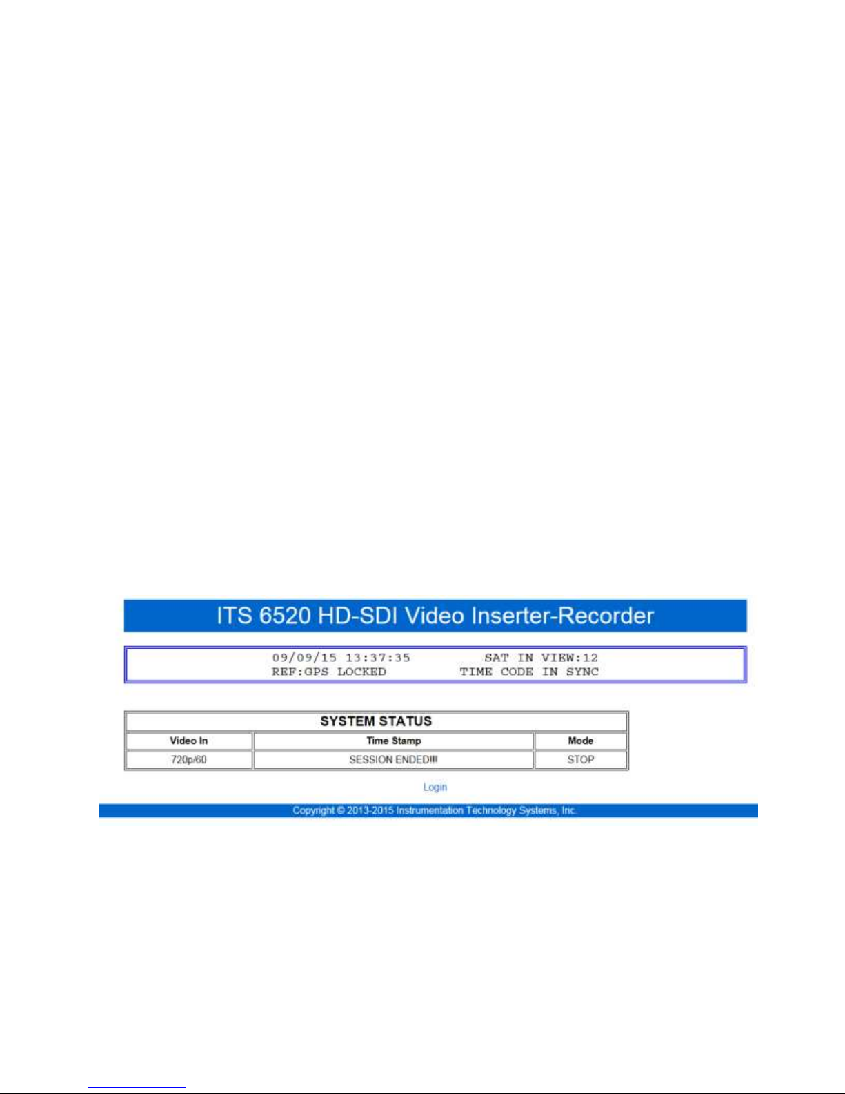
7.3 Webserver
The webserver is accessed from a browser (Windows Internet Explorer V11 or later, Firefox V ##
or later, Chrome) by entering HTTP:// and the current 6520 IP address. The factory default server
address is HTTP://192.168.150.90. This may be changed by the user from the GUI or by
command over the Ethernet and from the web server.
The Webserver is comprised of 6 pages
1. Home
2. Login (if configured for a login)
3. Communications
4. Recorder
5. Inserter
6. Administration
7.3.1 About the 6520 Webserver
Representative screen shots present within this manual are taken using Microsoft Internet Explorer
version 11. Other browsers such as Google Chrome and Firefox may appear differently.
Functions may also work somewhat differently. Use of earlier or later versions of Internet
Explorer may also change the appearance and “feel” and functionality of the webserver functions.
7.3.2 Home
The webserver organization begins with the HOME page. This page provides only system status
and permits no inserter or recorder control. If no login is required (see 7.3.3, below), the user may
move from page to page freely. If login is required, the only option will be to select the login
page.
In this instance, the pre-login Home Page appears as follows:
After login, the operator may also move freely from page to page.
6520 Inserter-Recorder Operation Manual Page 34
Page 42
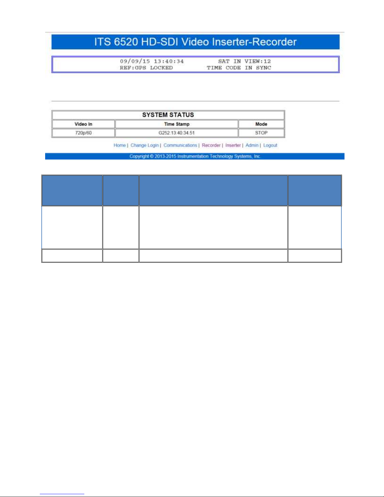
Status Item
Status
Other Possible Values
User
Programmable
Default
Video In
No
480i/x, 720p/y, 1080i/x, 1080p/y
x = fields/sec and can be 50, 59.97, 60
y=frames/sec and can be 25, 29.94, 30, 50,
59.97, 60
N
Mode
STOP
PLAY, RECORD
N
The possible values and meanings of the System Status are shown below
7.3.3 Login (software option)
A command (^YWSLnyy) or an input from the Configuration Utility can set the webserver to
require a username/password pair to gain access to controls or not. The ADMIN page also
provides this setting.
The factory default requires NO login. The default login is username [ADMIN] and password
[ITS19360] are case sensitive. Both can be changed once a login using the default user name and
password is employed.
Once the webserver is set to require a login page, this state may only be changed after a valid login
with the current username/password pair. If the requirement for login is removed, the username
and password pair is returned to the factory defaults.
When the requirement to login is set, a new login will be required after a period of webserver
inactivity. The length of the period of inactivity may be set (yy of the ^YWSL command) from 5
minutes (05), the minimum value and 99 minutes. A value of 00 disables login timeout (factory
default). When the time is disabled, the server will remain “open” until the browser session is
closed.
7.3.4 Change Login
The Change Login page is accessible after a successful log in. Both the user name and password
may be changed. Each field requires double entry to ensure that the user provides intended values.
6520 Inserter-Recorder Operation Manual Page 35
Page 43
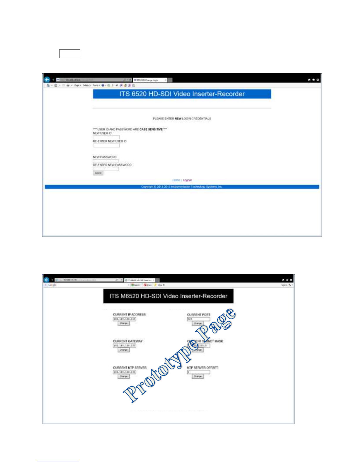
If only the password is to be changed, leave the user name fields blank. Similarly, if it is desired
to only change the user name, leave the password fields blank.
Click Submit to cause the change. The change is immediate.
7.3.5 Communications
The communications pages will display the current Ethernet IP address settings and address of the
NTP server to which the 6520 is directed, if any.
6520 Inserter-Recorder Operation Manual Page 36
Page 44
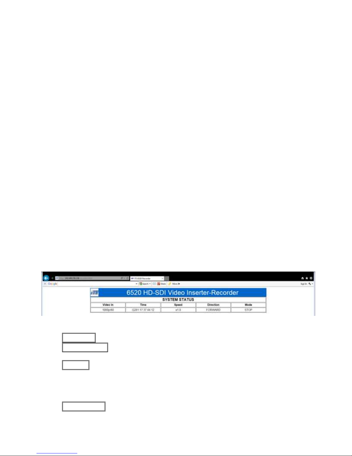
The Communications setup page shows current communications status and facilities to change:
1. IP address
2. Port number
3. Gateway address
4. Subnet Mask
5. Current NTP Server
6. NTP Server Offset
Changes to the NTP Server address or NTP Server offset are effective immediately. Any change
to the IP address or Baud Rates require a system reboot to become effective. System reboot can
be accomplished from the Administration page (7.3.8 Administrative page 48) or by cycling
power. After reboot, any new settings of IP address, port, gateway and subnet mask must be used
to reestablish communications with the 6520.
7.3.5.1 NTP Server Settings
The system time may be synchronized to an NTP (Network Time Protocol) server which may be
available to the network connection of the Ethernet port of the 6520. See NTP Time Reference
(Not implemented at this release) for more information.
When the Current NTP Server value is set to 0.0.0.0, this function is disabled (factory default).
When set to a valid address of an NTP server, the 6520 NTP client is ready to connect and
synchronize time to the server.
7.3.6 Recorder
The recorder page provides full control of recorder functions. One may record, event record,
playback, single step playback, vary playback speeds (search and slow motion) and stop.
Directories of previously recorded clips (if any) are displayed from which one may be selected for
playback.
7.3.6.1 STATUS
1. VIDEO IN; None, 480i, 720p/60, 1080i/59 or 60, 1080p/30, etc.
2. TIME STAMP: G or g, N or n, I or I; indicates GPS, NTP or IRIG reference locked
(capital) or unlocked (lower case) or never synchronized (*).
3. SPEED ; 1X is default for play or record. Zero (0) speed while in PLAY is stepping
capable a single frame at a time in forward (FWD>>) or backward (<<BWD) directions
from the currently displayed frame. Speed values may be 1/32xFR to 31/32xFR, 1xFR,
and 2xFR to 32xFR. The ##xFR is the multiple of the originally recorded frame rate (FR).
Record is always forward at 1X.
4. DIRECTION ; The current PLAY direction, forward or backward. In RECORD, the
direction is always forward.
6520 Inserter-Recorder Operation Manual Page 37
Page 45
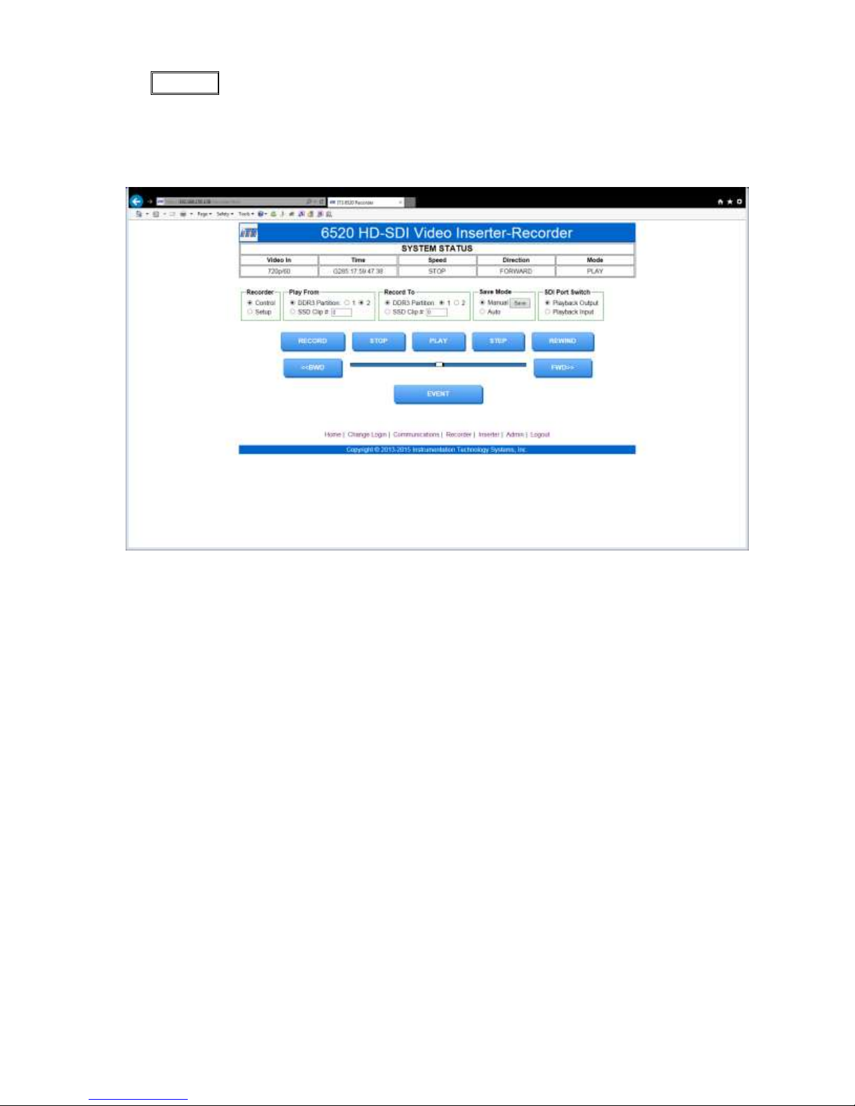
5. MODE ; STOP, PLAY or RECORD. (Play at zero speed is stepping).
7.3.6.2 RECORDER CONTROL
On the Recorder page, one may select Control or Setup. The screen below reflects the Control
page as shown by the state of the radio button in the Recorder frame.
7.3.6.2.1 Play From Frame
The play from frame provides settings and status regarding the current clip. Play from DDR or
SSD radio buttons determines the source of playback video. If there is more than one partition set
for the DDR3, one may select either partition as the active clip. The partition selected (1 or 2) will
set the current clip.
If SSD is the play from source, the clip number must be entered to set the active clip. If the value
is zero (0), the current clip will be the last recorded clip saved to the SSD. If a number is entered,
the number is the index value assigned by the 6520 when displaying the directory of video clips
available on the SSD, if any.
7.3.6.2.2 Record To Frame
When the DDR3 radio button is set, a RECORD will record video to the DDR3. If the DDR3 is
set to two partitions, the user may select which partition to which video will be recorded.
When the SSD is radio button is set, a RECORD will record video to the SSD. If the Clip # is zero
(0), the video will be recorded as a new clip in the next unused space on the SSD. If a valid clip
number is entered, video will overwrite that clip number with new video. Before this is finalized,
a confirmation form will open to ensure that the user intends to overwrite this previously recorded
clip. If a clip is overwritten, the new clip need not be the same length as the clip being
overwritten. If the new clip is longer, the overwritten SSD space will be consumed first, and then
new unused SSD space will be consumed until a Record-STOP is received or the SSD no longer
has capacity.
6520 Inserter-Recorder Operation Manual Page 38
Page 46

7.3.6.2.3 Save Mode Frame
The Save Mode Frame determines whether clips recorded to DDR3 are saved automatically to
SSD (Auto radio button) or must be saved by manually commanding it. When set to manual (radio
button), the SAVE button in the frame is enabled. Clicking on the SAVE button, causes the
current DDR3 clip (when partitioned, partition 1 or 2 may be selected) to be saved to the SSD.
7.3.6.2.4 SDI Port Switch Frame
In this frame, one can select what video is routed to the switched SDI output of the recorder.
When Playback Output is selected, the switched and unswitched SDI outputs are identical. When
the Playback Input is selected, the video routed to this output is that which is supplied by the video
source (live, DDR or SSD) prior to any playback overlay or metadata extraction.
7.3.6.2.5 Main Controls
1. RECORD; starts a record operation from STOP mode, either loop or continuous to the
RECORD TO device DDR3 or SSD. RECORD TO is set in the Recorder-Setup page.
The System Status frame will reflect this mode.
2. STOP; initiates an immediate stop of any play or record operation, even event record
during a delayed stop. An immediate stop is delayed until a complete frame (last frame) is
recorded. In stop mode, the STATUS SCREEN will automatically be presented to the SDI
output if previously enabled. If the STATUS SCREEN is not enabled, the SDI output will
present the live video input if any.
3. PLAY; Causes the recorder to begin rendering the currently active clip. Play speed may
be 1X or the last selected play speed prior to a STOP. When Play speed is set to zero, the
recorder may be stepped. The direction of step or play is set by the <<BWD or FWD>>
buttons.
4. STEP ; Will advance to the next frame at play speed zero in the direction previously
selected (<<BWD or FWD>>). The recorder must be in PLAY mode.
5. REWIND; is only active when in STOP mode and sets the recorder to the first frame of
the currently active clip.
6. EVENT: is hidden when not set in EVENT RECORD mode, EVENT appears on the
page, the recorder has been set in EVENT RECORD mode. The system must be in
RECORD mode (recording) for this button to have an effect. When recording, the operator
may click on EVENT to set an event marker manually when this button is activated. This
will initiate a delayed stop determined by the number of frames previously set to be
recorded after an event marker is received from any source (EVENT button, Ethernet
command, or input discrete).
7. << BWD ; Sets the play mode to decrement frame number during a step or a play at any
speed.
8. << FWD ; Sets the play mode to increment frame number during a step or a play at any
speed.
9. Slider Bar; This slider dynamically adjusts playback speed from 1/32FPS-31/32 FPS,
1FPS, 2FPS to 32 FPS where FPS is the previously recorded frame rate. This is only active
while i
6520 Inserter-Recorder Operation Manual Page 39
Page 47
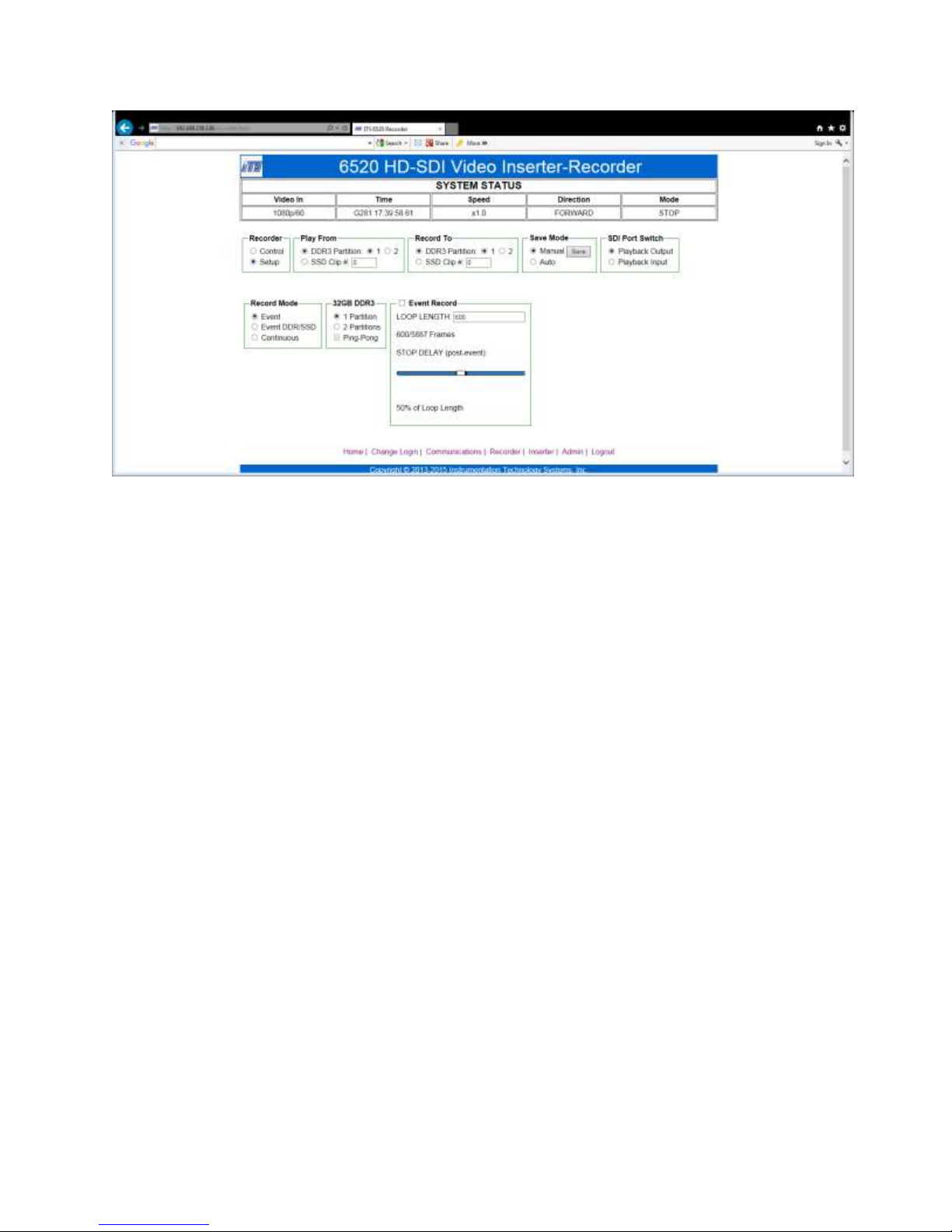
7.3.6.3 SETUP
The Recorder, Play From, Record To, Save Mode and SDI Port Switch frames are repeated here
and function as described in 7.3.6.2 RECORDER CONTROL page 38.
7.3.6.3.1 Record Mode Frame
When the EVENT radio button is selected, the event recording mode is enabled. In this mode, the
DDR3 is placed in loop record mode and will record to the currently active partition (1 or 2, if
any). If Ping-Pong is selected, recording will start in the partition selected by the radio button.
After an event is captured, loop recording will begin in the next partition until a second clip is
captured. After the second clip is captured, recording will stop unless the Save Mode is set to
Auto. In that event, after the first event is captured, it is saved to SSD while the second partition is
active in loop recording mode waiting for an event trigger. This will continue (ping-pong) until a
STOP is commanded or the SSD exhausts capacity.
When the Event DDR/SSD radio button is set, the DDR3 may only have one partition. On
RECORD, the DDR3 is set to loop record mode. When an event is triggered, the entire loop
recorded will be saved to SSD and recording will continue to the SSD until a STOP is commanded
or the SSD exhausts capacity.
When the Continuous radio button is set, a RECORD command will record video to the SSD as
the next clip or starting with the clip number commanded at set up. The DDR3 is used as a frame
buffer in this mode and does not record in a loop. Recording to the SSD will continue until a
STOP command is received or the SSD exhausts capacity.
7.3.6.3.2 ## GB DDR3 frame
This frame will report the total capacity of the DDR3; 16GB or 32GB.
Selecting the 1 Partition or 2 Partition radio button sets the configuration of the DDR3. If this is
changed, any clips recorded to the DDR3 will be lost. A confirmation form will open when this
setting is changed to ensure the intention of the operator.
When set to two partitions, the DDR3 recording capacity for each partition is one-half of the total
6520 Inserter-Recorder Operation Manual Page 40
Page 48

Image Fame Format
≈Frames/GB
480 (SD)
900
720
335
1080
170
capacity, which is one-half of the frame count. This condition is reflected in the Event Record
frame.
The Ping-Pong check box (Not available when Event Mode is DDR/SSD) will record a loop in
the active partition. Any previously recorded video will be lost in that partition. The EVENT
control will be set to yellow and active. When an event marker is received (manual, discrete input,
or Ethernet command), the recording will continue for the stop delay period. Immediately upon
completion, the active partition will be switched to the other partition and will commence a loop
record waiting for an event marker.
If the system is not in AUTOSAVE (to SSD) mode, only a single ping-pong cycle will be
executed. On completion, the EVENT control will be grayed out and become non-functional and
the EVENT RECORD mode will be OFF.
If the system is in AUTOSAVE (to SSD) mode, the “ping” event of the ping pong cycle will be
saved to the SSD (if present of course) in parallel to initiating loop record on the other partition
(pong partition). When a “pong” event is captured, this clip will be saved to SSD (new clip
number) and the “ping” partition will commence loop recording once more. This will continue
until event record mode is turned OFF or the SSD becomes full or is removed or STOP is
commanded (RECORDER CONTROLS, manual buttons, or Ethernet command).
7.3.6.3.3 Event Record frame
Event Recording is enabled when the checkbox of this frame is set.
The Loop length is a User Entry in frame count. When video is present, the 6520 will calculate
the storage space required in the DDR partition to save that many frames. If there is sufficient
space, this length in frames will be displayed in the RECORDER CONTROL section. If there is
insufficient space, the number off frames that the 6520 calculates will fit based on the current input
video format will be displayed and the background of this cell will be changed to yellow. If no
video is present, the 6520 will accept without warnings any value in the range of 00010 to 40000
frames.
The following table is provided to assist in determining frame count capacity requirements
When video is applied this frame will report the maximum number of frames of the applied video
that will fit in the DDR3 partition.
The Stop Delay determines the number of frames to be recorded after an event signal is received
in EVENT RECORD mode. Stop Delay is entered as a percent of the total number of frames of
the event record loop. The slider bar permits values from 10% to 90% of the total record loop. In
the example webserver page, the loop record length is 600 frames. At a 60 frame per second frame
rate, 10 seconds of video will be recorded in the loop. The STOP delay is 50%. This setting will
record 300 frames (5 seconds) of video after the event marker is received. The total clip will
surround the receipt of the event marker equally (5 seconds before and 5 seconds after the event.).
6520 Inserter-Recorder Operation Manual Page 41
Page 49

Please note, that if record in this mode is initiated and an event occurs quickly, the total clip
captured may not be the full loop length. In the example described earlier, it is possible that an
event could occur 2 seconds after RECORD is initiated. This situation would only allow 120
frames to record before the stop delay is initiated (post event frames). In this case, the total clip
would be 420 frames; 120 before and 300 after. At 60 frames per second, 2 Seconds before and 5
seconds after; only a 7 second clip.
7.3.7 Inserter
The inserter webpage provides status and several controls to set overlay conditions for both the
record channel and playback/live monitor channel.
There are overlay elements that can be set for either channel. These elements are:
Whether Annotation is “on” or “off” (enabled)
The font size and color
Boresite and movable Crosshair presence, size, color and location (movable only)
System Time format and resolution
The GPS position
The IP address of the recorder
The video format present
Text pass through lines
The methods to enable (cause them to appear), position (row and column), color and size as
appropriate, are common to both the record and playback channels.
Each setup, however, is independent. For example to overlay GPS position on both the playback
and record channels, each setup must be selected on the webserver form and each parameter is set
separately.
Other elements are unique to the record and playback channels and are listed below:
Record
o Write of Metadata Time
o Write of an Event Marker
o Write of Frame Count
Playback
o Extraction and Display of Metadata Time
o Measurement and display of Latency using system time and metadata time
7.3.7.1 Record Channel
The record channel is the SDI input channel to the 6520. From the webserver, overlay elements
(burned into the video during recording) can be added in. More importantly, the MISB
Microsecond Timestamp can be written to the VANC.
Set up of KLV option packs are not supported at the webserver. Setup, write and overlay of KLV
pack fields may only be accomplished using the 6520 Configuration Utility.
6520 Inserter-Recorder Operation Manual Page 42
Page 50
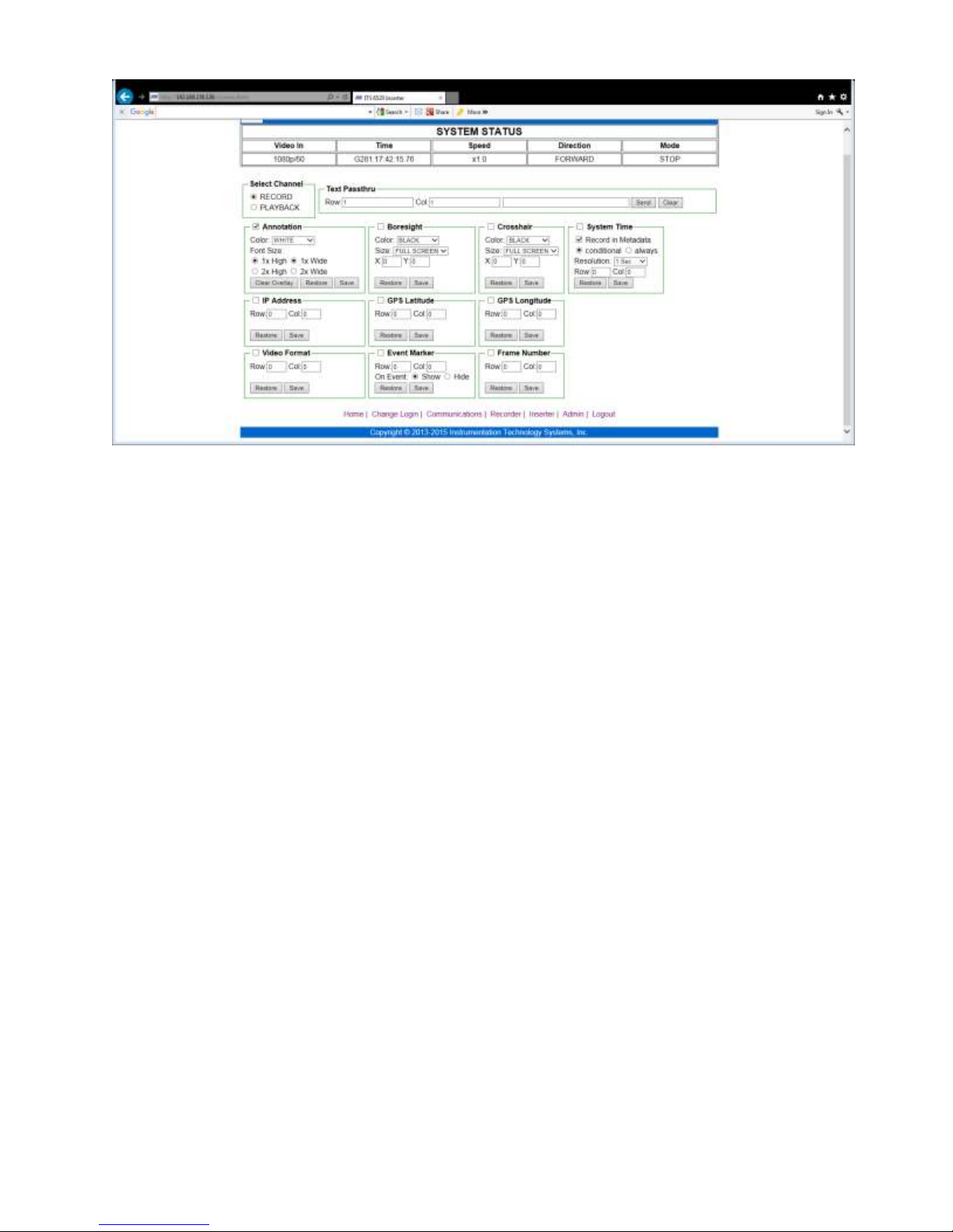
7.3.7.1.1 Annotation
Annotation is enabled (overlays appear) by clicking the Annotation frame check box. Within this
frame, the size of the text and color may be set. These settings apply to all text overlay on the
frame.
7.3.7.1.2 Boresite
The boresite crosshair is a fixed graphic (horizontal and vertical line) where the intersect of the
lines is the center pixel of the frame. This is true for any supported video format.
Boresite is enabled (overlay appears) by clicking the Boresite frame check box. Within this
frame, the size (full screen, medium and small) of the crosshair and color may be set.
7.3.7.1.3 Crosshair
The crosshair is a graphic (horizontal and vertical line) where the intersect of the lines may be
positioned anywhere on the frame. A Cartesian plane format is used (x, y) where x=0 and y=0
places the crosshair at the center of the frame. This position would be true for any supported
format. Positions other than the center are specified in two-pixel increments from the center
where x values less than zero move the center to the left of center and positive values move the
crosshair to the right of center. Similarly, positive y values move the center up, above the frame
center line and negative y values move the center down, below the frame center line. Each value
of y represents a full line increment.
Crosshair is enabled (overlay appears) by clicking the Crosshair frame check box. Within this
frame, the size (full screen, medium and small) of the crosshair and color may also be set.
7.3.7.1.4 System Time frame
In the record channel, this frame enables the specification of two functions; display of the system
time as synchronized by GPS, NTP or IRIG and writing a MISB timestamp to line 9 of each frame
of the incoming video.
The display of system time (overlay) is enabled by clicking the checkbox of the System Time
frame. This action does NOT write the MISB Metadata Timestamp.
In order to cause the 6520 to write the MISB Metadata Timestamp to line 9 of the frame, one must
6520 Inserter-Recorder Operation Manual Page 43
Page 51

also click the Record in Metadata checkbox. These check boxes are independent in that if
Record in Metadata is clicked, the MISB timestamp will be written to the incoming SDI video
whether the System Time check box is clicked or not.
If the Conditional radio button is set, the 6520 will write a MISB Microsecond Timestamp if and
only if no such timestamp is present on starting at the first sample of line 9 compliant with the
MISB Microsecond Timestamp as defined in MISB 0605.3. If no packet or any other packet is
present, the packet will be written (or overwritten) as prescribed by MISB.
If the Always radio button is set, the 6520 will write a MISB Microsecond Timestamp starting at
the first sample of line 9 compliant with the MISB Microsecond Timestamp as defined in MISB
0605.3, thus overwriting any packet, including a previously written MISB Timestamp packet that
may be present in the incoming SDI video.
The Resolution specification only applies to the overlay of system time. Any overlay of system
time will be “burned into” the recorded video. Resolution has no effect on the resolution of the
MISB Timestamp recorded.
Resolution may be set from 1 second to 1 microsecond in 1 decade steps (6).
Row and Column specifies the placement of the first character (*, g, G, i, I, n or N) of the System
Time overlay on the frame. The color and font size is specified by the Annotation frame.
7.3.7.1.5 IP Address frame
The IP Address frame must be clicked to cause the IP address to be overlaid on the incoming SDI
video. This value will be four valid octet values formatted as ###.###.###.### and a port address
of a value from 0 to 65535.
The first character of this value may be located on the frame by entry of the Row and Column.
Text color and font size is specified by the Annotation frame.
7.3.7.1.6 GPS Latitude frame
When the checkbox of this frame is clicked the latitude reported by the internal GPS receiver will
be displayed in overlay on the frame of the incoming SDI video. This value will only be displayed
when the GPS is locked to one or more GPS satellites after have calculated a position fix. A
position fix requires visibility to a constellation of not less than four GPS satellites for three (3) to
five (5) minutes. Prior to a fix, not value will appear. The value is updated at the 1PPS rate.
The first character of this value may be located on the frame by entry of the Row and Column.
Text color and font size is specified by the Annotation frame.
7.3.7.1.7 GPS Longitude frame
When the checkbox of this frame is clicked the longitude reported by the internal GPS receiver
will be displayed in overlay on the frame of the incoming SDI video. This value will only be
displayed when the GPS is locked to one or more GPS satellites after have calculated a position
fix. A position fix requires visibility to a constellation of not less than four GPS satellites for three
(3) to five (5) minutes. Prior to a fix, not value will appear. The value is updated at the 1PPS rate.
The first character of this value may be located on the frame by entry of the Row and Column.
Text color and font size is specified by the Annotation frame.
7.3.7.1.8 Video Format frame
When the checkbox of this frame is clicked the format of the incoming SDI video will be
displayed. The value is only displayed with a valid SDI signal of one of the formats supported by
6520 Inserter-Recorder Operation Manual Page 44
Page 52

the 6520. Values expected are 480i, 576i, 720p, 1080i, 1080p.
The first character of this value may be located on the frame by entry of the Row and Column.
Text color and font size is specified by the Annotation frame.
7.3.7.1.9 Event Marker frame
When the checkbox of this frame is clicked a special character, , may be displayed on the
incoming video frame.
When the On Event - Show radio button is set, no event marker is overlaid on the frame until an
event signal is received by the 6520 and only when the record mode is one of the event modes.
When the On Event – Hide radio button is set, the event marker is overlaid on the frame until an
event signal is received by the 6520 and only when the record mode is one of the event modes.
These options enable the operator to choose when an event marker appears on the video; before
(hide) or after (show) an event. This feature is intended to help locate and identify the frame
before and after an event has been captured in an event mode recording.
The character may be located on the frame by entry of the Row and Column. Text color is
specified by the Annotation frame. The size is fixed.
This frame only appears in the record channel since events are not relevant to the playback channel
in real time.
7.3.7.1.10 Frame Number frame
When the checkbox of this frame is clicked the 6520 will begin overlay of a frame number. The
format is ###. On each 1PPS (one-second mark) the internal frame counter is set to 000. As each
new frame is detected (equivalent of vertical sync in analog video), the counter is incremented.
Video frame rates of 29.97 will generally yield 029 as a max count and 60 frames per second video
would yield a max of 060. This tool is intended to assist video analysis and simplifying
identifying a frame of interest without loss of the precise timestamp.
The first character may be located on the frame by entry of the Row and Column. Text color is
specified by the Annotation frame. The size is fixed.
This frame only appears in the record channel.
7.3.7.2 Playback Channel
The playback channel is the SDI output channel to the 6520. Video may originate from the output
of the record channel (live video), the DDR3 (recorded in volatile memory) or the SSD (recorded
in non-volatile memory if present).
When the playback channel is set to display the Status Screen, all overlay originates from within
the 6520 and cannot be modified by the operator. The text color and font size are set at the
factory.
From the webserver, overlay elements can be added in that were not burned in during recording.
Most importantly, the MISB Microsecond Timestamp can displayed as well as all or some of the
fields that are defined in any KLV option packs that may have been written to frames in the VANC
at record time. However, set up to extract and/or overlay KLV option packs are not supported at
the webserver. Setup, extract and overlay of KLV pack fields may only be accomplished using the
6520 Configuration Utility.
When the Playback radio button is set, the form displayed by the browser changes as shown above.
6520 Inserter-Recorder Operation Manual Page 45
Page 53
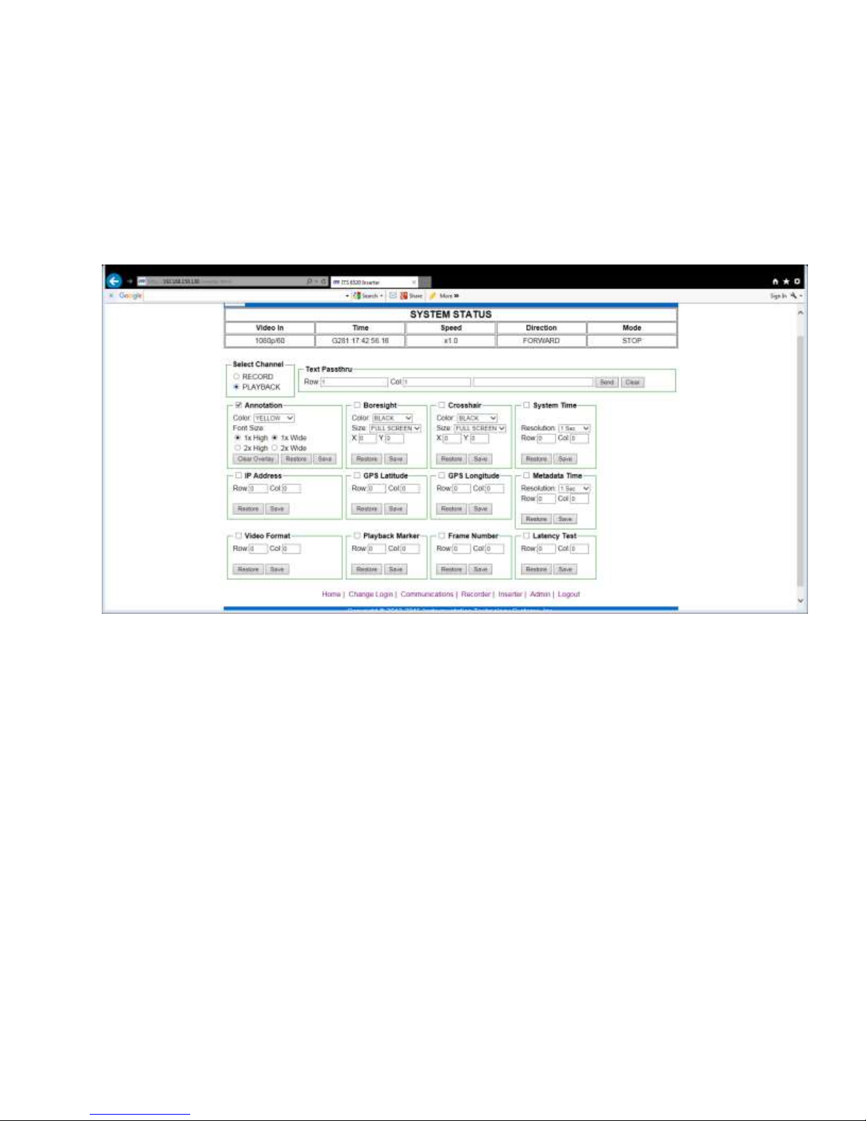
The Text Passthru frame (see 42Record Channel page 42), Annotation frame (see Annotation page
43 ), the Boresite frame (see Boresite page 43), the Crosshair frame (see Crosshair page 43 ), the
IP address frame (see IP Address frame page 44) the GPS Latitude frame (see GPS Latitude frame
page 44), the GPS Longitude frame (see GPS Longitude frame page 44) and the video format
frame (see Video Format frame page 44) all behave the same why as they do on the Record
channel. The overlay, however, is burned in at the time of live video or playback. None of these
fields will appear when the Status Screen is present on the output.
The only frames described below are those unique or with unique behavior in the playback
channel.
7.3.7.2.1 System Time
Only the overlay of the internal time of day value of the synchronized system time can be specified
in this frame. When the System Time check box is set, the system time may be overlaid on the
live or playback video. The time will be reflective of current time and will differ from any time
overlaid at the time of recording. If it is desired to overlay the time when recorded, use the
Metadata Time.
The Resolution displayed may be one second to 1 microsecond in decade increments.
The first character may be located on the frame by entry of the Row and Column. Text color and
font size is specified by the playback Annotation frame.
This frame only appears in the playback channel.
7.3.7.2.2 Metadata Time
Only the overlay a MISB Timestamp previously embedded in the frame on line 9 can be specified
in this frame. When the MISB Timestamp check box is set, the value MISB Timestamp will be
extracted and formatted as Julian or Gregorian as specified on the Administration page. In a
manner similar to the System Time, the resolution of the metadata time display may be set from 1
second to 1 microsecond in decade increments.
The time displayed will be reflective of time captured when recorded (playback of video) or that
being impressed by the record channel during live video display or any valid MISB Microsecond
6520 Inserter-Recorder Operation Manual Page 46
Page 54

Timestamp embedded upstream by another device.
The first character may be located on the frame by entry of the Row and Column. Text color and
font size is specified by the playback Annotation frame.
This frame only appears in the playback channel.
7.3.7.2.3 Playback Marker
The Playback marker, PV, may be overlaid by clicking on the frame‟s checkbox. This string may
be used to identify when playback video is being displayed at the output SDI. In many situations,
it may be hard to distinguish between live video and playback when the scene is static (e.g. the
barren desert). This marker is a tool to help a user identify which is being seen at a display.
The first character may be located on the frame by entry of the Row and Column. Text color and
font size is specified by the playback Annotation frame.
This frame only appears in the playback channel.
7.3.7.2.4 Frame Number
This field may be overlaid by clicking the frame‟s checkbox. The frame number is generated
using the same method of the record channel frame number generator (see Frame Number frame
page 45). However, this is not the frame number of the playback video. It is a frame number
generated by the playback channel triggered on each playback vertical sync equivalent. The frame
number counter is reset on the current system time one-second rollover (1PPS) and is not
synchronized to the playback video time. Therefore, it is highly likely, that this frame number will
differ from the recorded frame number.
This frame number may also be displayed during live video feed to the playback channel from the
record channel.
The first character may be located on the frame by entry of the Row and Column. Text color and
font size is specified by the playback Annotation frame.
This frame only appears in the playback channel.
7.3.7.2.5 Latency Test
This test determines the difference between the current system time and the metadata time
captured in the MISB metadata time stamp. One such measurement might be to measure the
latency between the MISB timestamp written in the record channel and when it is extracted by the
playback channel.
Other uses could be to measure the latency from when a MISB timestamp is written by and ITS
inserter or another video source to when it is captured by the playback channel as live video after
transit over an array of devices such as H.264 compression encoder/decoder pairs, SMPTE 2022-6
fiber encoder/decoder or other transport schemes.
When the Latency Test frame checkbox is set, the latency value may be displayed.
The value is always in microseconds and is taken as the System Time minus the MISB timestamp.
The first character may be located on the frame by entry of the Row and Column. Text color and
font size is specified by the playback Annotation frame.
This frame only appears in the playback channel.
6520 Inserter-Recorder Operation Manual Page 47
Page 55
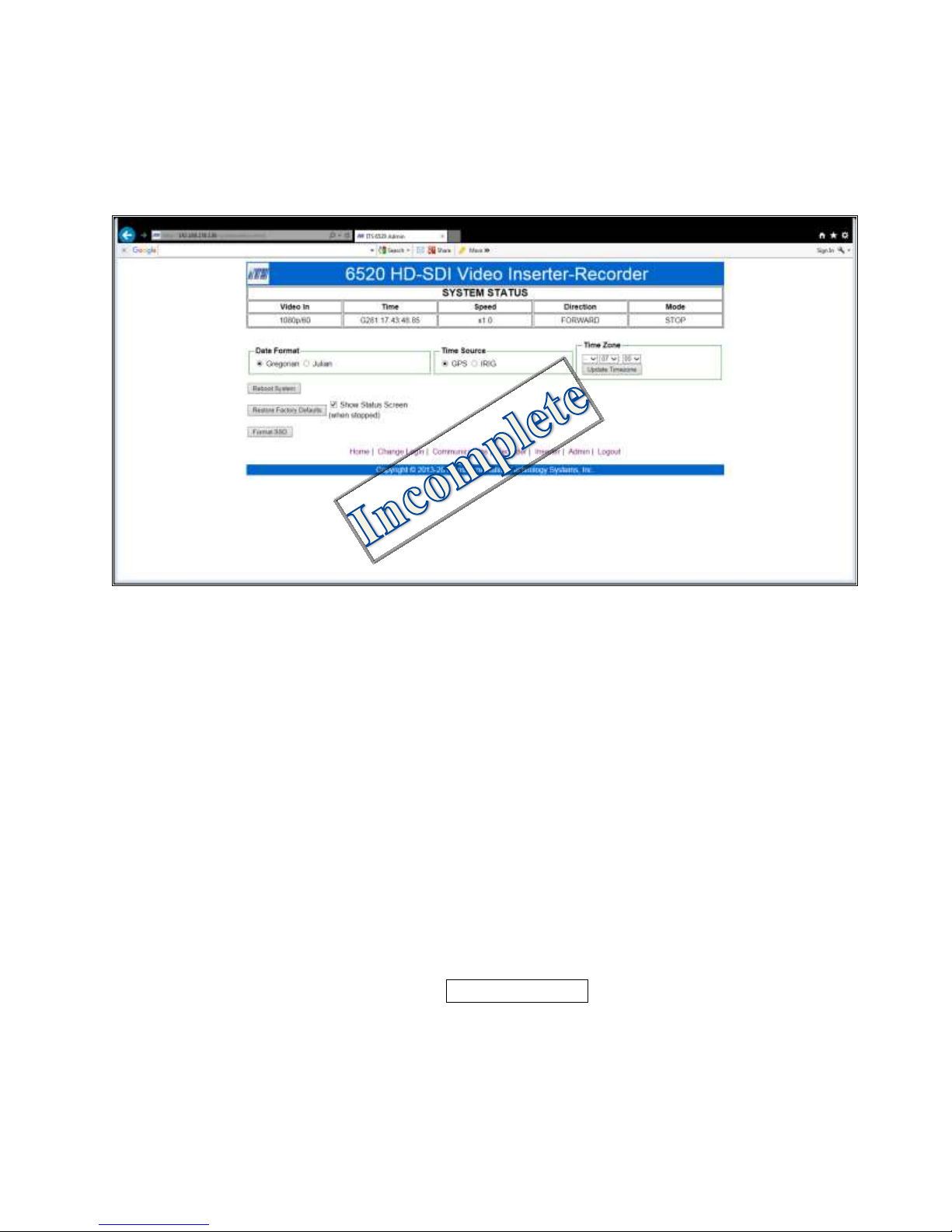
7.3.8 Administrative
The administrative functions are special functions that give the operator the opportunity set global
features of the recorder such as the time reference two which the time master of the 6520 is to be
synchronized, the time zone offset to be used to localize GPS or NTP time and other functions.
7.3.8.1 Date Format
The Date Format frame sets all time display (system time or metadata time) to the Gregorian
(MM/DD/YY HH:MM:SS.ssssss) or Julian format. (DDD:HH:MM:SS.ssssss). This is a global
setting and establishes the display format for both the record and playback channels.
7.3.8.2 Time Source
The Time Source frame determines to which reference the system time master is to be
synchronized. This is a global setting.
7.3.8.3 Time Zone
The Time Zone value is an offset to the UTC time reported by the internal GPS receiver. Time
Zone has no effect when the reference is IRIG. Time Zone has no effect until the system time
master is first locked to GPS after power up.
Time zone may be set to ±12 and +15 minutes. This setting will revise the time reported by the
values set with this frame by adding the offset to the UTC time. This is a tool to localize the
time reported during overlay. It does not affect the metadata time.
This value is not set in the recorder until Update Time Zone is clicked. The effect is
immediate and can be observed in the webserver System Status frame.
7.3.8.4 Login required frame
When the Yes radio button is set, the webserver will add the Login Page. The Home page will
only present status and not permit navigation to any other page except login.
6520 Inserter-Recorder Operation Manual Page 48
Page 56
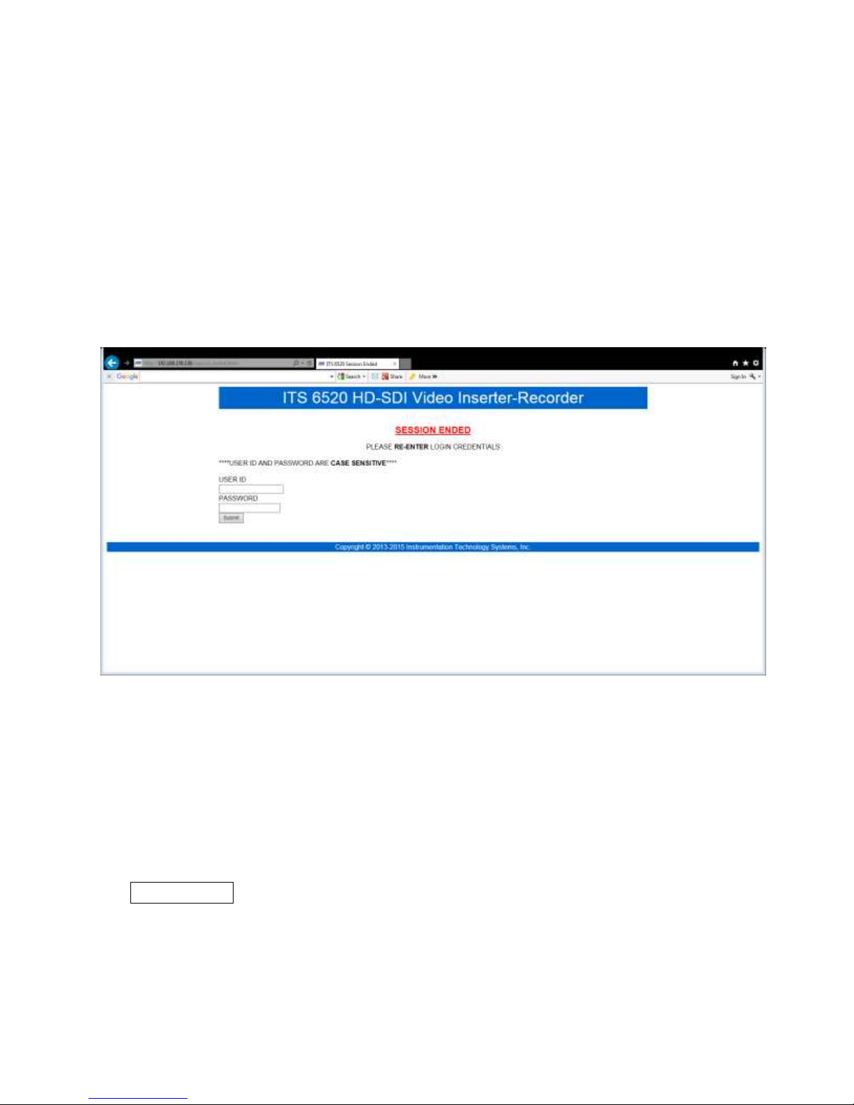
When the No radio button is set, the webserver will remove the login requirement and provide full
navigation of the webserver pages
The default login is
User name=ADMIN (case sensitive)
Password = 6520ITS (case sensitive)
7.3.8.5 Login Timeout frame
Login Timeout permits a logged in user to set the length of time of non-activity that will cause the
current login access to expire. In the example shown, if webserver remains inactive for 9
consecutive minutes, login will expire.
The webserver will return to the home page and the system will require a new login to gain access
to the control pages as shown below.
A login timeout =0 will disable timeout, causing the system to never timeout the current login.
However, the session will terminate and require a new login when the browser is closed. The
range of the login timeout is 01 to 99 minutes. No other values will be allowed.
7.3.8.6 Show Status Screen
The Show Status Screen checkbox determines whether the green Status Screen displays on the SDI
output (playback channel) when in STOP mode. When this checkbox is set, the Status Screen will
be displayed at the unswitched SDI output.
7.3.8.7 Reboot System
The Reboot System button starts this system over in a manner similar to cycling power.
Communication with the webserver will be interrupted during reboot. This may require
reconnecting to the system with the browser in use. If the login option has been selected, a new
login will be required.
6520 Inserter-Recorder Operation Manual Page 49
Page 57

Communication with the 6520 may be lost. Be
sure that the system can be connected to a
network that spans 192.168.150.xxx in order to
7.3.8.8 RESTORE FACTORY DEFAULTS
RESTORE FACTORY DEFAULTS will set the saved screen to a cleared screen, change the IP
address to 192.168.150.92 port 23, the subnet mask to 255.255.255.255 and the gateway to
192.168.150.100. No login will be required, but the default password will be changed to 6520ITS
(case sensitive) and the user name will be ADMIN (case sensitive).
Text color will be restored to BLACK on both the record and playback channels and intensity will
be set to full saturation. No metadata time will be written. The Switched SDI output will be set to
present the output of the Playback channel (same as the unswitched output). The DDR3 will be
set to one partition, no event record mode. Playback will be directed to SDI. Serial port
communications will be set to 9600 baud.
CAUTION
reestablish communications.
Clicking on this button requires confirmation.
7.3.8.9 Format SSD
When an SSD is present this button, Format SSD, will write the ITS proprietary format to an SSD.
If the SSD is previously recorded, access to the data will no longer be available. However, format
does not CLEAR the SSD from a data perspective. It simply rewrites the directory as new. This
is a fast operation.
The ITS format is not recognized by any version of Microsoft™ Windows©, Linux, or other
widely used operating system. The ITS format is single purpose (write uncompressed video data)
and has been designed to maximize write speed of the SSD.
7.3.8.10 Clear DDR
CLEAR DDR performs implements DOD 5220.22-M method C. (see 3.4.4.1 DDR3 CLEAR
page 18)
7.3.8.11 Clear SSD
CLEAR SSD Performs DOD 5220.22-M Method C then method H. (see 3.4.4.2 SSD CLEAR
page 18)
6520 Inserter-Recorder Operation Manual Page 50
Page 58
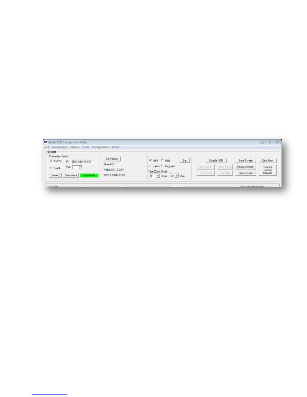
7.4 Graphical User Interface (GUI) Utility.
ITS supplies a CD with an application that will run under Windows XP or Windows 7. This
software is a GUI that provides a simple intuitive means to control the 6520, display built in fields
and place text and crosshairs. A means is provided to save a set up (store the entries on the GUI
form) and restore a set up (preload the form from a previously saved file). This setup file may be
used with the 6055C-nGHD, 6980G-HD or 6041G-HD GUIs as well.
The GUI receives data from the 6520 it is connected to that reveals the memory capacities that are
available (DDR3 and SSD), and what options are included (e.g. Camera Sync, SSD, S3, etc.).
With this message, the GUI self-configures to enable the features necessary to permit control.
7.5 Global GUI Functions
The upper section of the main form provides the ability to connect to a 6520, determine the
firmware versions currently operating in the unit and set time and general setup, and restore
functions.
To connect to a 6520 over Ethernet, enter the IP and port number and click on Connect.
You may also connect via a serial port. Select the Serial radio button the select connect. The
Connection Information changes to allow you to set the host computer COM Port and the
BAUD Rate.
Successful connection is indicated to the right of the Connect/Disconnect buttons.
Once connected the GUI will query the connected unit to learn the configuration and adjust itself
to make the proper controls and settings available. It will also retrieve the current firmware
version of the main processor, the GPS receiver and each video processor. One can query the
6520 connected for the current firmware versions at any time by clicking Get Version.
7.5.1 System Functions
The system functions are
Select the time reference and display format.
Set the time zone offset (only applicable with a GPS time reference)
Save and Load system setups
Send a setup to the Record, Playback or both channels at once.
Clear the GUI form
Save the current screen (playback channel only)
Restore the saved screen
Clear the screen (playback or record)
6520 Inserter-Recorder Operation Manual Page 51
Page 59
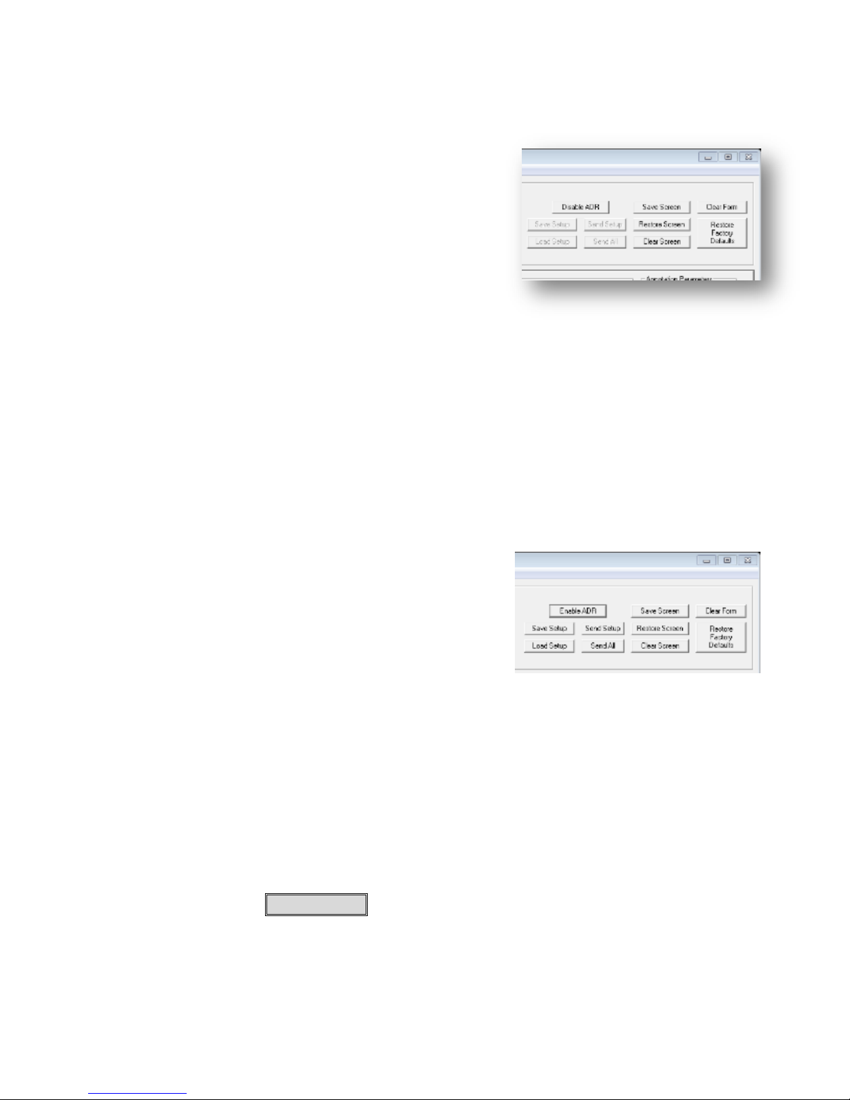
Restore Factory Default
7.5.2 The ADR
The ADR is an acronym for an Aggregate Data Request.
This command and response pair returns a packet of data
that is used by the GUI (and can be used by a
programmer) to determine the current status of important
elements of the recorder. This feature is used by the GUI
to populate the form with current settings. This is
important since, multiple users can be connected via
Ethernet and the front panel of the rack mount unit can
change the state of the machine, begin and stop recording
and affect the memory capacities. The GUI sends the
ADR out approximately ten times per second to maintain a perceptually live status.
When making changes to settings, this background operation can sometimes make it difficult to
change a setting. This is especially true when saving a setup. It is important to be sure that the
setup intended is saved to a reference file.
In order to overcome the side effects of continuous status feedback, one may disable the ADR
function.
One MUST disable the ADR to enable the SAVE, LOAD, SEND and SEND ALL setup
functions.
7.5.3 Save Setup
Save Setup is a GUI unique feature that when ADR is
disabled will collect all of the settings of the main form and
save them to a file that you may name and store anywhere
accessible from the host workstation. When the ADR is
disabled and Load Setup is clicked a subformwill open
(File) that will let you find and select a previously saved
form file (*.mcf) . When loaded, all of the settings (check
boxes, start, line, free text fields, colors, etc.) will be loaded into the form. After loaded one may
simply select the channels for which you wish these settings to apply and click Send Setup. The
text, graphics and embedded fields will be reloaded to the selected channels in there respective
channels. Any number of MCF files may be saved facilitating the development of many overlay
setups, each may apply to different missions or set up conditions. After this operation, the ADR
may be reenabled.
7.5.4 Load Setup
When the ADR is disabled, Load Setup will open a file selection form that can be used to select a
previously saved setup. The setup may be named anything you chose and be saved anywhere in
your workstation access universe. Once loaded, the main form will be populated with every
setting saved at the time SAVE SETUP was clicked.
All inserter parameters including metadata parameters are saved. Recorder parameters saved
includes the event loop length and delayed stop values, DDR3 partition selection (1 or 2), whether
set for autosave DDR3 clips to SSD or not and whether recording will be to DDR3 or SSD. After
this operation, the ADR may be reenabled.
6520 Inserter-Recorder Operation Manual Page 52
Page 60

6
7.5.5 Send Setup
Send Setup will, when ADR is disabled, send all of values present in the main form for the
selected channel (Record or Playback) along with all recorder settings. After this operation, the
ADR may be re-enabled.
7.5.6 Send All
Send all will when ADR is disabled; send commands to the 6520 that will send all inserter
commands set in the form in both of the Record and Playback channels as well as the recorder
settings. After this operation, the ADR may be re-enabled.
7.5.7 Restore Factory Defaults
Restore Factory Defaults is global and will clear all saved settings EXCEPT the IP address and
port6.
7.5.8 Save Screen
Save Screen is channel specific and will save the contents of overlay text and locations of enabled
embedded fields to a local channel flash memory. When Restore Screen (channel specific) is
clicked, these saved values will be restored to the overlay.
7.5.9 Clear Form
Clear Form removes all settings of all user selectable parameters from the main form.
7.5.10 Clear Screen
Clear Screen removes all overlay text (not graphics) from the selected channels.
7.6 Inserter Tab
Many of the controls and settings of the inserter tab are the same for the record and playback
channels. However, each channel is independent and must be set independently.
Some functions are exclusive to the Record channel such as:
Writing Metadata Time
And writing metadata optional packets.
Enabling and specifying the location to overlay an event marker
Enabling and specifying the location to overlay a frame counter.
Some functions are exclusive to the playback channel such as
Enabling and specifying the overlay of the content of a MISB metadata timestamp
Enabling and specifying the location of fields (some or all) of metadata option packs for
which a defining CSV file has been imported.
Extraction of metadata packet data to a file.
When Restore Factory Default is accomplished from with an attached keyboard with the LCD menu, the IP address
and Port is also changed back to 198.162.150.90 port 23.
6520 Inserter-Recorder Operation Manual Page 53
Page 61
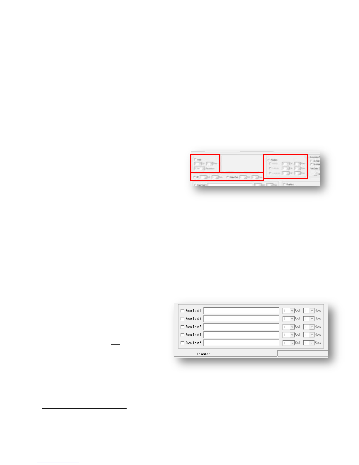
7
7.6.1 Common Controls
The following controls appear for both the Record and Playback Channels. Their behavior is
identical with regard to overlay, color selection and character size. However each is independent
in that they must be set as desired for each channel independently.
The Save Setup function will save all of the Record and Playback channel functions. This feature
enables one to save both record and playback inserter settings at once. On a reboot or power cycle,
this previously saved setup may then be loaded and with using Send All will re-input all of the
settings saved to the recorder all at once.
7.6.1.1 Embedded Fields
The 6520 has a host of internals fields that may be displayed anywhere on the video by simply
specifying what field and where.
Embedded fields are:
Time
IP address
Video Format (e.g. 480i, 576i, 720p,
1080i or 1080p)
Position (only when GPS option is
included and when locked, displays latitude and longitude and if selected can display
position in MGRS7 format).
To cause an embedded field to be display, select the corresponding checkbox and then specify the
column (start) and row (line) that the field is to appear. In the instance of time, one can also
specify the resolution displayed (1 second, 100 ms, 10 ms, 1 ms, 100 µs, 10 µs and 1 µs).
The maximum start and line values are dependent on the incoming video format (e.g. 480i, 576i,
720p, 1080i or 1080p).
7.6.1.2 Free Text Fields
There are five (5) free text fields. These fields can be filled with any ASCII text and placed at any
column (start) and row (line) that the
format permits. The text line must be
enabled with the checkbox. Two or
more such text fields may be on the same
line.
Please note that you are not limited to
only 5 fields of text overlay in any one
channel of the 6520. Under program
control one can place 30-120 characters
per line and 30 to 32 lines of text on the
video depending on format.
MGRS is Military Grid Reference System and presents a letter code identifying a 100Km square on the surface of the
earth and two 5-digit numbers represent the northing and easting in meters from the lower left corner of the square.
6520 Inserter-Recorder Operation Manual Page 54
Page 62

7.6.1.3 Annotation Parameters
The color of all text overlay may be set in any one of eight colors (black,
white, red, blue, green, cyan, magenta or yellow).
The intensity may also be set. Setting intensity here (as is true for a
programming input) will override the setting of the front panel pot.
Moving the front panel pot will override any programmed setting.
The aspect of the text overlay may also be changed from the standard 5x7
to a 7x9. The text size may also be changed to two times high, two times
wide or both. ALL text is changed to this aspect with this setting for the
SELECTED channels.
7.6.1.4 Graphics Control
When the general function of Graphics is selected (checkbox)
one may set the mode and color of each graphic independently.
These settings will only apply to the selected channel (Record or
Playback). The color is also independent from that selected for
text overlay as well.
The color of each graphic may be set to off (no graphic) black,
white, red, blue, green, cyan, magenta and yellow. The modes
are disabled (off), full, medium and small.
When controlling the Boresite, graphic the center of the crosshair
is always in the video center. When controlling the Crosshair,
there is a similar selection for color and mode. Additionally, there is a control to offset the center
of the crosshair in the x or y direction from the center of the video. The values entered are ±pixel
(x) or ±line (y) counts. For example, to position the crosshair 10% above the center and 5% to the
left of center of a 1080p video source, one would enter +11 and +20.
6520 Inserter-Recorder Operation Manual Page 55
Page 63
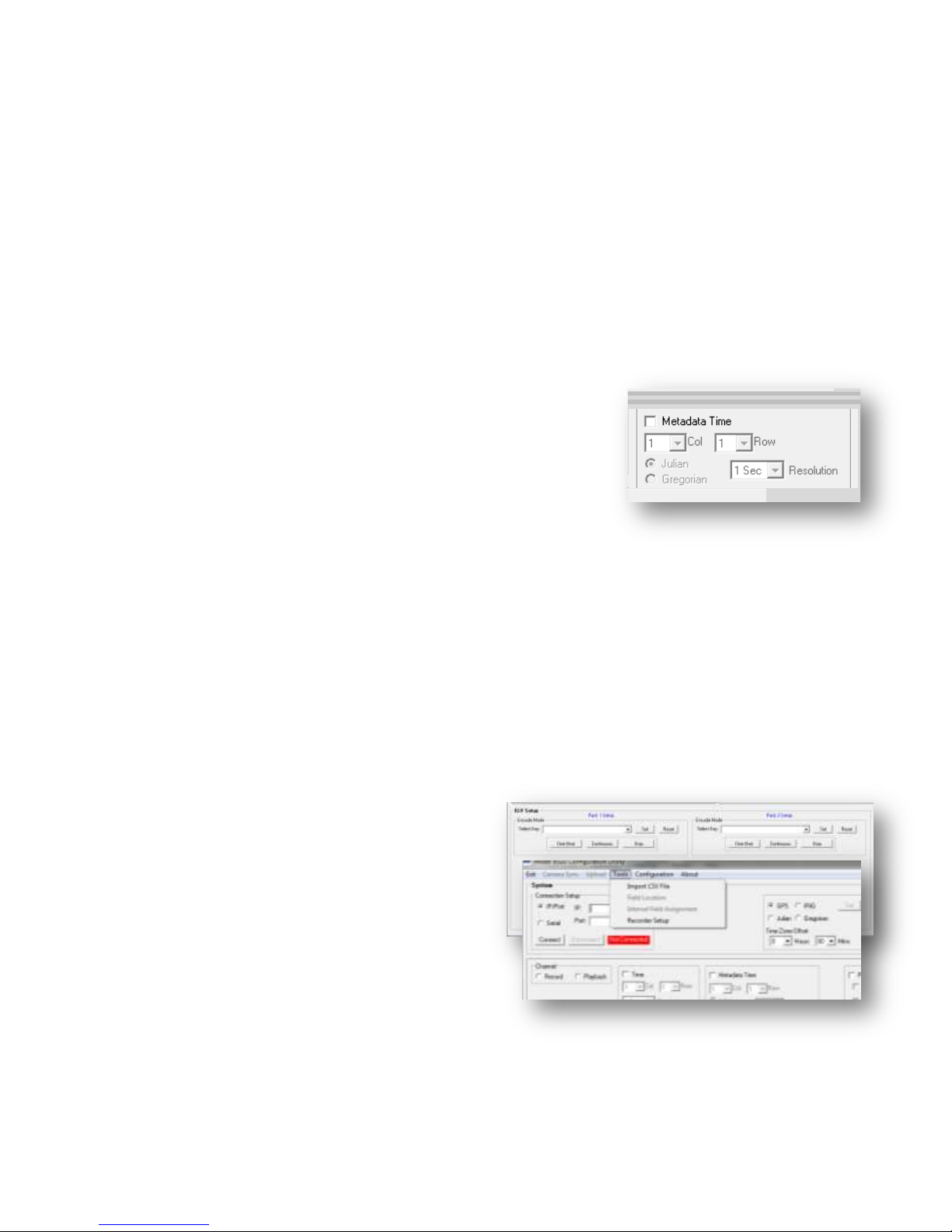
7.6.2 Record Channel Inserter
The Record channel Inserter functions have a few unique capabilities that do not appear in the
playback channel. In summary, the functions that are present in Record only are:
1. Write the metadata timestamp
2. Write metadata option packs (up to two).
3. Insert internal fields into metadata packets
4. Write an event marker
Descriptions of each of these functions follow.
7.6.2.1 Metadata Time
When checked the Record channel will write metadata
timestamps to the VANC space of the incoming video
formatted in accordance with MISB 605.3.
MISB 605.5 Microsecond Timestamp KLV pack is a 64-bit
value representing the number microseconds since January 1,
1970, the UNIX epoch. The 6520 record channel engine
collects time from the internal time master at the end of active
video (EAV) of the last line of the previous frame. It will be
written starting on the first sample after the start of active video
(SAV) on line 9 of the frame.
If the Record channel has been setup to insert additional KLV option packs (up to two more), these
packs will be written in accordance with the settings for KLV setup.
Metadata timestamps are written conditionally, however. That is, if a MISB timestamp is present
in the incoming video stream, the 6520 will not overwrite this time stamp. If no timestamp is
present, the 6520 will insert its own timestamp collected from the time master.
7.6.2.2 Metadata Option Packs
If the Record channel has been setup to insert additional KLV option packs (up to two more), these
packs will be written in accordance with the
settings for KLV setup.
To set up the recorder for inserting option packs
one must create a pack design. This can be
accomplished with the aid of the ITS KLV
Software Toolkit. This toolkit and its manual is
included at no extra cost with each 6520.
The key design (as CSV file) must be imported
into the GUI first. This is accomplished from
the Tools menu, “Import CSV file. Clicking on
this menu item will open a window with which
you may select the CSV file representing the key
of your design and choosing. Select the file. When complete the GUI will display a message that
the CSV file has been successfully imported.
6520 Inserter-Recorder Operation Manual Page 56
Page 64
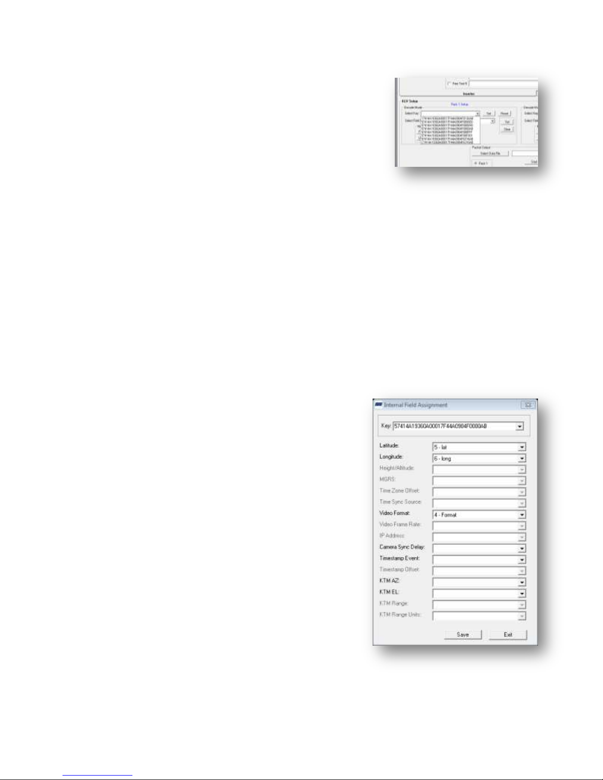
Once completed, this key and any others previously imported will appear in the KLV setup dropdown. If there is no desire to display any metadata in the
record channel, then simply select the desired key and click
“Set”. The GUI will now send commands to the 6520 that will
prepare the unit to receive data encapsulated in our command
as described in the REMOTE CONTROL FUNCTIONS for
packet functions. A test program such as the ITS KeyTest©
GUI may then be used to send a data steam to the recorder.
The data will be structured as KLV data and placed into a
SMPTE 291 M type 02 packets and inserted on the next line 9
the system sees in the incoming SDI stream.
7.6.2.3 Merge Embedded Field Data into Metadata
The 6520 has a host of internal fields that may be integrated into the KLV metadata packets. The
steps to accomplish this task are:
1. Define a field in the metadata that complies with the specification for the internal data type.
The specifications for each data type are included in the ITS KeyTemplate©. Using the
template locate the internal field in the key design at any location within the 235 bytes that
may be available.
2. Import the key converted to a CSV.
3. Select the key from the Tools menu as described in Metadata Option Packs (page 56).
4. Link the internal fields to the metadata pack from the Tools menu Internal Field
Assignment menu and save the links.
When setup correctly, the 6520 will overwrite the byte
locations with the internal data that has been correctly
linked to each incoming (via Ethernet) for that key. The
result will be an option KLV metadata pack payload
consisting of external data and internal data.
The data available for internal field link are shown in the
Internal Field Assignment form screen shot. The list may
change from time to time and the available fields will
depend on the equipment features that are available.
In the example shown, the fields enabled (not grayed out)
are fields where the key contains byte length and format
specifications matching the internal field requirement.
The text boxes will list the labels for each key field that
matches the specification of that particular internal field.
Any field with a blank text box is not linked to the key.
As shown, the GPS latitude and longitude and the video
format will be inserted into the metadata. Any clip
recorded properly recorded this way will contain the GPS
latitude and longitude at the time the frame was received
by the record channel during recording. This will be true
for all other linked internal fields.
6520 Inserter-Recorder Operation Manual Page 57
Page 65
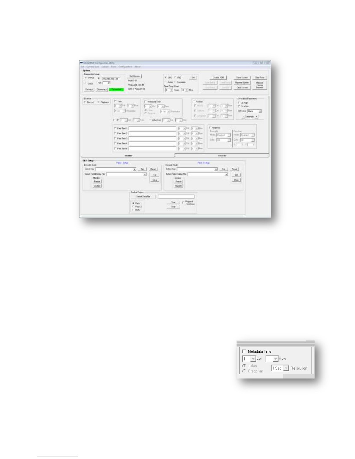
7.6.3 Playback Channel Inserter
When the Playback radio button is selected in the Inserter Tab, the form changes as shown below.
The revised form will now permit the operator to display metadata time, and the KLV Setup frame
changes to permit overlay of metadata on the playback video where the source of the overlay data
is the VANC SMPTE 291M KLV packets that are present. In addition, the KLV setup frame
adds a subframe which enables the operator to extract and collect the metadata to a file.
The Playback channel is always in metadata read mode. All of the overlay, metadata extraction
and metadata overlay functions are available whether the input to the channel is a live video feed
from the record channel or a prerecorded video feed from the DDR3 volatile memory source of the
SSD non-volatile memory source.
7.6.3.1 MISB Metadata Timestamp
If a MISB 0605.3 Microsecond Timestamp is present in the video stream, the 6520 will read that
time on each received frame. When selected for display it will
display the time read from the metadata in the format set for
global time (Julian or Gregorian). The resolution may be set
here in a similar manner to the record channel. If no metadata
timestamp is detected the message –No Metadata- will appear
starting at the row/column (line/start) specified for this field.
When the metadata timestamp is present, it will appear as
MHH:MM:SS… or mHH:MM:SSS… signifying that it is
metadata time. Capital “M” signifies that when the time was collected for this frame, the reference
was locked to a standard (e.g. GPS or IRIG). When a lower case “m” is present, the time collected
was not locked to the time standard.
6520 Inserter-Recorder Operation Manual Page 58
Page 66
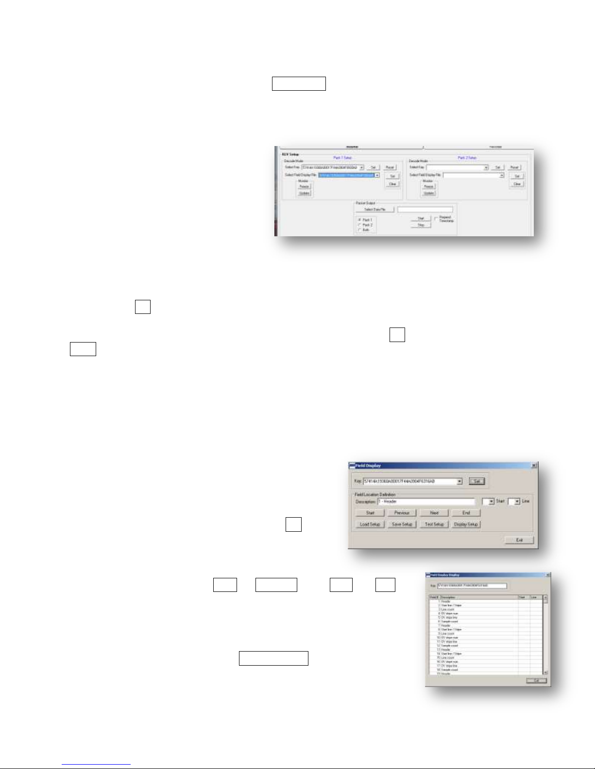
In order to display the Metadata Timestamp one must first set the Metadata Time checkbox. Select
the column and row it is desired to display the time, set the format (Julian or Gregorian) and the
resolution (1 second to 1µsec). Then click Send Setup (ADR must be disabled to permit this).
The metadata time should appear the location set. Text color is the same as all other text.
7.6.3.2 KLV Option Packs
If the playback channel has been
configured to display the contents of
KLV option packets (up to two), the
metadata will be parsed and ASCII
text will be formatted and inserted into
each frame in accordance with the
location and format instructions
embodied in the KLV setup for the
Playback channel.
In order to display or extract option
packs, the 6520 Playback channel must be given the key number and structure (display) in order to
accomplish this. On the inserter tab, playback radio button, go to the KLV Setup frame. Select a
key and click Set. Then in the dropdown for the Select Field Display File, select the
corresponding file name (often this is the same key number, but it is not required). If the field
display file is encoded for the key selected, you will be able to click Set in the Set/Clear box. The
Clear button deselects this file from the set up and clears the text box.
At this point, if a VANC space KLV metadata pack having the key value selected is in the video
stream on line 9, the extracted and formatted contents of the data will be displayed as specified in
the Field Display file.
7.6.3.3 Creating a Field Display
In order for specific fields of the KLV payload to be parsed, formatted and overlaid on the video,
each field to be display must be located at a row and
column. Only those key payload fields with row and
column assignments will be displayed.
From the Tools menu, open the Field Location item.
A form will open, Field Display. In the key frame
select a key from the drop down list and click Set. If
valid, the label for the first field defined for this key
will appear in the description box.
The operator may then sequentially step through each
field of the key by clicking on Next or Previous. The Start and End
will select either the first key field or last respectively. When a field of
interest is shown in the Description box, one may enter a row (line)
and column (start) for display. If the current field is not to be display
enter nothing the start or line boxes.
At any time during this process, the Display Setup button may be
clicked. This action will open a form listing each field in the selected
key and show the row and column, if any, each is assigned for display.
6520 Inserter-Recorder Operation Manual Page 59
Page 67

When this assigment is complete, the field location set up may be saved to a file by clicking
Save Setup on the Field Display form. This file may be named anything you choose. Saving a
field location setup facilitates reuse of the same key with the same overlay design. One a field
display has been designed, simply click Load Setup from the Field Display form and the design
embodied in the selected field display file will be loaded into the system. This may be verified by
clicking on the Display Setup button and observing the field list and start (column) and line (row)
numbers assigned to each field is what was intended.
If one edits the field locations of the loaded setup, the modified design may be saved once more to
the same file name, or saved to a new file name for future use.
This field location file is the same file name that is set in the Playback form of the KLV Setup
frame described in 7.6.3.2 KLV Option Packs on page 59.
6520 Inserter-Recorder Operation Manual Page 60
Page 68
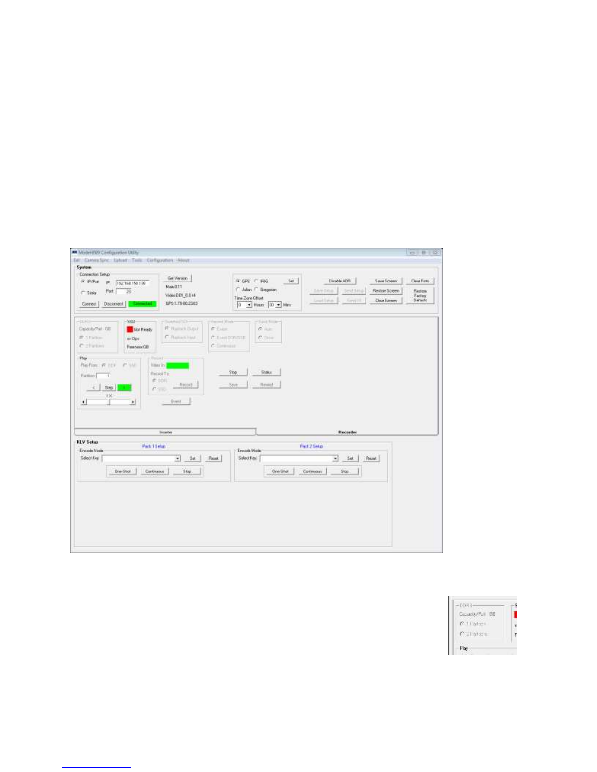
7.6.4 Recorder Functions
The recorder functions at the GUI and the Webserver are essentially the same. One can set to:
1. Record to SSD or DDR
2. Partition the DDR
3. Event record in one of three modes
4. Auto-save or manually save clips recorded to DDR
5. Format or clean an SSD
6. Select a clip for playback
7. Control playback speed and direction.
8. Overwrite or delete a clip from SSD
9. Enable or disable the status screen
These functions are accessed from the Recorder tab on the main form or from the Tools/Recorder
Setup Functions.
7.6.4.1 DDR3 Frame
In this group, the total capacity of each DDR3 partition is reported. If there is one partition, the
value show equals the total capacity of the installed DDR3 memory. If there
are two partitions, each partition is one-half of the total capacity.
If there is no DDR3 or the system is unable to address it, FAIL will be
reported.
The partition controls permit the operator to establish a recording memory of the full capacity of
the DDR3 or divide it into two equal and separately functional recording areas. When changing
this configuration, any previously recorded clip saved in DDR3 will be lost.
6520 Inserter-Recorder Operation Manual Page 61
Page 69
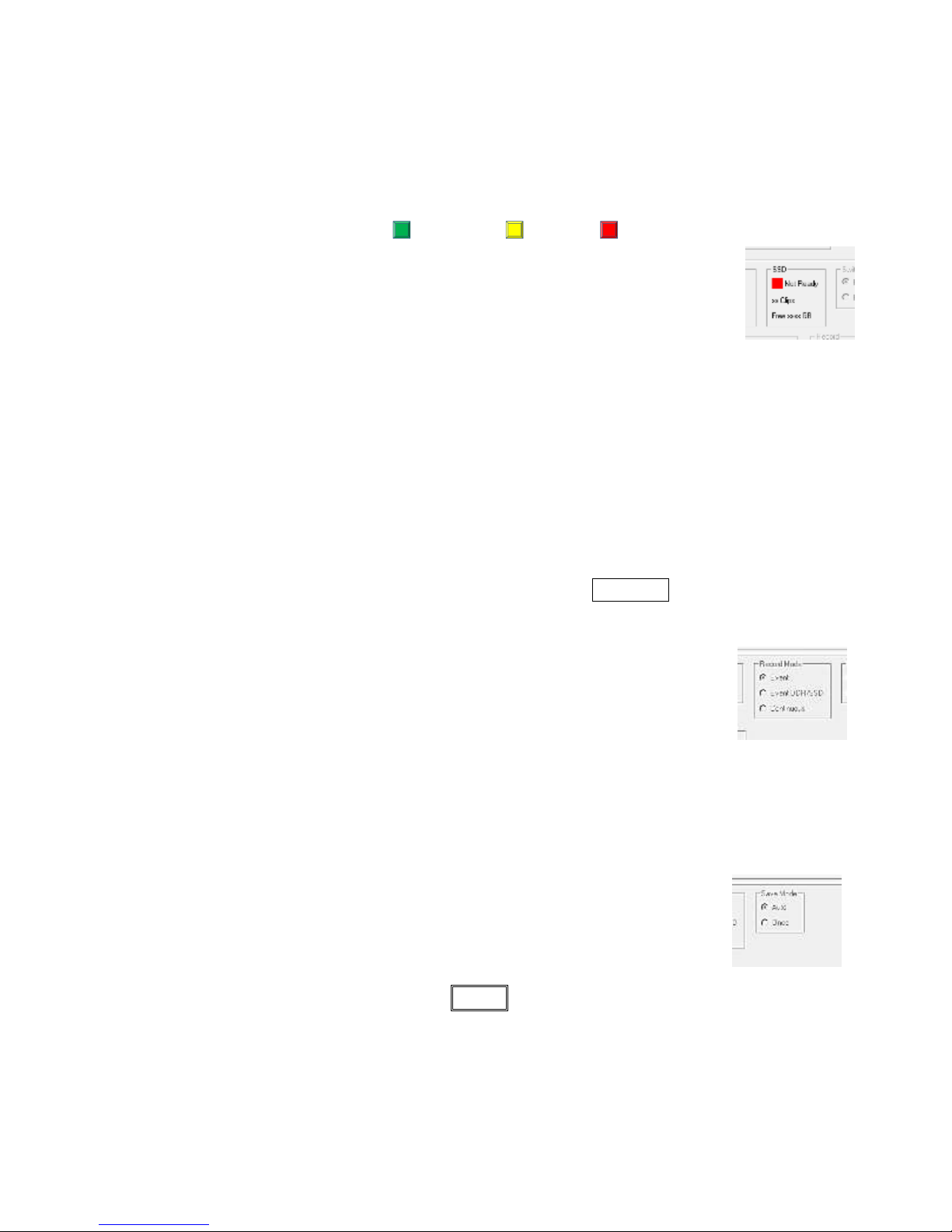
When more than one partition is set for the DDR3, several functions become active in the recorder:
1. Ping-Pong event mode.
2. Playback from DDR partition select. This is similar to select a clip number to be played
back from SSD.
7.6.4.2 SSD Frame
The SSD frame reports status, Ready , Not Ready , or FAIL . Additional status is provided
as follows:
1. Ready: will report the number of clips, 0-n, that are saved on the SSD and
the number of free space available for new recordings in gigabytes (GB).
2. Not Ready: None Installed, Needs Format, Full are possible messages to
accompany a Not Ready state.
3. Fail: No communication is established between the recorder and the SSD. In this instance
a simple possible method to overcome this is to open the drive, insert a key and unlock the
drive from the carrier. This action (without removing the drive) simply turns the power to
the SSD off and resets the communication interface. Relock the SSD and observe that
power is restored from the indicator lights on the drive. This may restore the system to any
of the ready states. There a many possible causes, however this status indicates that the
SSD, the SSD carrier, the SSD receiver (inside the 6520) the SATA interface or a main
board failure is preventing the 6520 from reading or writing to the SSD currently installed.
7.6.4.3 Record Mode Frame
In this frame the type of recording that will be initiated with the RECORD button is set here.
Fundamental record modes are:
Event: This mode will require to DDR3 in a loop. The length of the loop
is that set by the user in the Recorder Setup menu or by default, the length
of the current partition. When an event is signaled by an Ethernet
instruction, input discrete or by a manual control button, the percentage of
the loop previously set by the user in the Recorder Setup menu or by
default 50% of the Event Loop.
If set to Ping-Pong (in the Recorder Setup menu and only available when two partitions are
set for the DDR), the second partition will begin recording in a loop and will be waiting for
an event signal.
If the system Save Mode is set to Auto, the previously recorded clip in
the first partition will be saved to SSD while the second partition records
and prepares to capture the next event.
If set to Once, no save of the DDR3 clip in the inactive partition will be
saved to SSD until the user clicks the SAV E button on the main form. When clicked, the
clip saved in the inactive (previously recorded event clip) will be saved to the SSD as a
new clip on the SSD.
When in Ping-Pong mode and save is Once, the recorder will record the first partition (first
event), then record the second partition (second event) and stop.
6520 Inserter-Recorder Operation Manual Page 62
Page 70
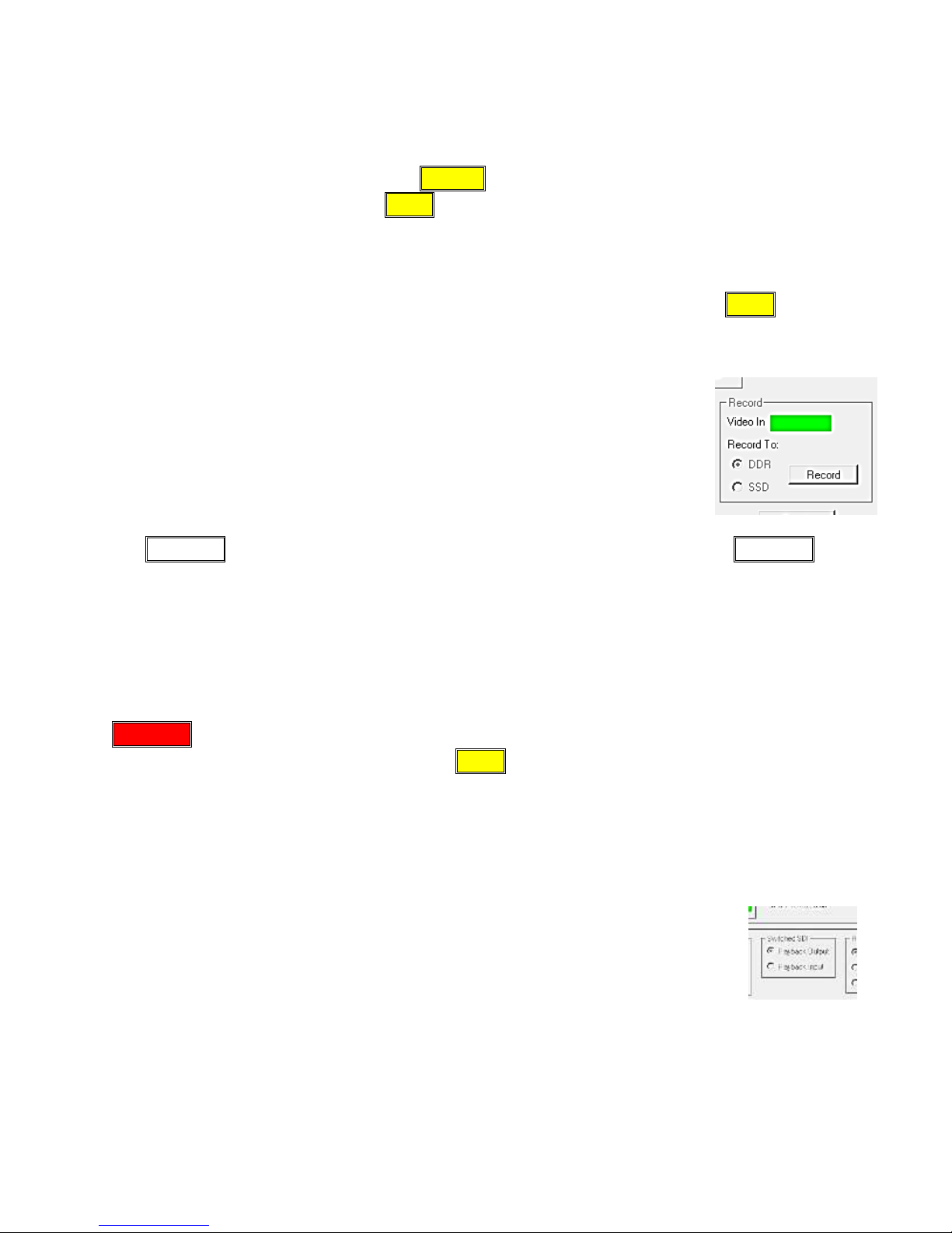
1080P
Event DDR/SSD: This mode is an expanded event record mode where the DDR3 will
record in a loop at the length specified as described earlier. In this mode, the DDR3
partition is one. When an event is signaled, the entire loop (pre-event video clip) will be
saved to the SSD while the 6520 continues to record post-event video. An event may be
signaled manually by clicking on EVENT, by command or by a manual control button.
Recording post-event until a STOP is invoked or the SSD free capacity is exhausted. See
3.3 Recorder Characteristics beginning on page 8 for more information about event
recording features.
Continuous: This mode will use the DDR3 as a video buffer only. The DDR partition is
set to one. All video will be saved to SSD continuously in one clip until a STOP is
invoked or the SSD free capacity is exhausted.
7.6.4.4 Record Frame
The Record frame reports the status of incoming video as follows:
1. No Video
2. 480i
3. 576i
4. 720p
5. 1080i
6. 1080p
The RECORD button will cause the 6520 to record clips as previously setup. The RECORD
button will be inactive when:
1. No video is present
2. The DDR3 is not ready
3. The SSD is not ready if the SSD is the Record To destination
4. The SSD is not ready and Save mode is set to Auto
5. The SSD is not ready and the record mode is set to Event DDR/SSD
6. The SSD is not ready and the record mode is set to Continuous.
RECORD will start will start recording function and be colored red to indicate that recording is
taking place. This will remain so until a hard STOP is invoked, a delayed stop is invoked by the
parameters set for event modes, if record video is lost or the detected video format is changed, or
when the record to device (DDR or SSD) free capacity is exhausted.
When Record To: is set to SSD, the recorder is set to Continuous mode.
7.6.4.5 Switched SDI Frame
The Switched SDI frame enables the operator to change the source of the Switched
SDI output (BNC). The source is either the output of the playback channel or the
input to the playback channel. When set to the output, both SDI outputs (switched
and unswitched) have identical SDI video present. When set to Playback input,
this BNC connector will have
1. A live video feed from the record channel during recording and when stopped, or
2. The playback output of the DDR3/SSD before any metadata decode and playback channel
overlay is imposed.
For more information on this feature, see 3.3 Recorder Characteristics beginning on page 8.
6520 Inserter-Recorder Operation Manual Page 63
Page 71
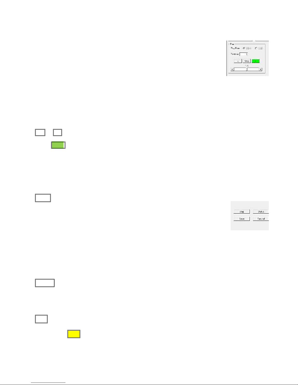
7.6.4.6 Play Frame
The Play frame contains several choices to be made before actually initiating a
play function.
Play From selects the source of recorded video, DDR3 or SSD.
When DDR, the clip number refers to the partition number. If only one
partition is set, play assumes partition 1 whether entered in the Clip No. box or
not. If the DDR is configured with two partitions, the partition number desired
should be entered. The default is always partition 1.
If the SSD is chosen as the Play From source, a clip number should be entered. If no clip number
is entered, a play action will the last clip saved to SSD. The clip number being played will be
shown in the Clip No. box when play is active. A list of clips currently available on the SSD is
found in the status frame, see 3.4.1 Clip List page 15 for information describing the status frame.
7.6.4.6.1 Play direction & Speed
< or > are buttons that set the direction of play. If the play speed is zero, clicking either button will single step
in the direction chosen one frame at a time. When play is active, the appropriate play button (< or >) will be colored
green ( > > indicates playing forward). The speed of play is indicated as follows:
1. 0xFR: single step
2. 1xFR normal play speed; the slider is center.
3. 2xFR to 32xFR and is accomplished by frame skipping. Moving the slider to the right increases speed.
4. 1/32xFR plays at normal speed, but each frame 32 times.
5. 2/32xFR, to 1xFR plays is accomplished by playing frames multiple times as above.
7.6.4.7 Stop
STOP is an immediate stop of play or record function. Any play or record stop
will terminate at the end of the current frame being played or recorded. When
play or record is stopped, this button is yellow.
If the Status Screen has been enabled, the recorder will switch to it.
If the Status Screen has NOT been enabled, the recorder will switch to live video
(e.g. video present on the Record channel input if any.)
In order to continue to view the playback, set the playback speed to zero rather than Stop. This
keeps the 6520 in playback mode. In this mode, a frame of the Current Clip will be present on the
SDI output.
7.6.4.8 Rewind
Rewind will set the DDR3 or SSD (play from selection) to the start of the first frame of the
current Clip. The currently active clip is either the last clip recorded or a clip directly selected by
the user.
7.6.4.9 Save
Save will save the last clip recorded to the DDR3 to SSD (if ready). If the clip has already been
saved, the user will be asked if it is desired to overwrite this clip. If not, the save operation will be
aborted. The Save button will be colored yellow while a save is in process. During save
operations, continuous recording or playback functions are disabled.
6520 Inserter-Recorder Operation Manual Page 64
Page 72

7.6.4.10 Status
The STATUS button sets a function that will display the status frame at the output of the playback
channel any time the 6520 is stopped (not play zero speed). When STATUS is set this button is
yellow, else gray. For more information about the status frame, see 3.4.1 Clip List page 15.
6520 Inserter-Recorder Operation Manual Page 65
Page 73
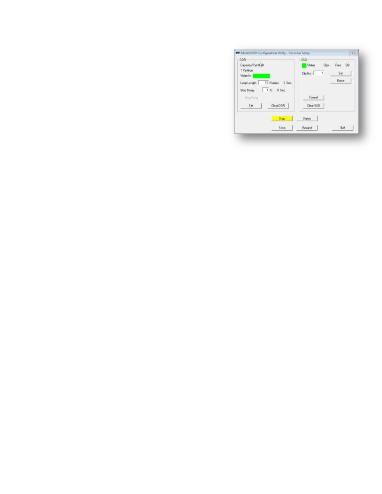
8
7.6.5 Recorder Setup Functions
The recorder setup functions are accessed from the main
form in the Tools menu. This form provides the ability to
set event loop length, stop delay, clear the DDR or SSD,
erase clips, select a playback clip and format the DDR.
Repeated on this form for convenience is the ability to
invoke a stop, display the status frame, save a DDR clip to
SSD and rewind the current clip. Ping-Pong function in
event record mode is set on this form as well.
On open, the status of the DDR and SSD (if present) are
displayed.
7.6.5.1 Loop Length
Loop length is the recording time of an event loop. The
loop length is expressed in frame count. The time of the loop cannot actually be known until video
is present at the record channel input.
If no video is present, the 6520 will accept without warnings any value in the range of 00010 to
40000 frames. Loop length time may be by dividing the frame count by the frames per second of
the incoming or expected video input.
In order to estimate capacity needed for the format and frame rate, frame sizes are: 1.2MB bytes at
480, 3.1 MB bytes at 720 and 6.2MB at 1080. Loop length storage requirements are calculated by
(frame count)*(bytes/frame). In general, the DDR loop with only 1 32GB8 partition can hold
approximately 31,700 frames. At 59.97 frames per second (NTSC standard frame rate), the
maximum loop time for this format would be about 528 seconds. At the other end of the spectrum,
when a 1080 frame is to be recorded the 32GB loop would hold up to 5,600 frames. At an NTSC
frame rate of 59.97 FPS, a loop of approximately 93 seconds could be configured.
When video is present, the 6520 will calculate the storage space required in the DDR partition to
save that many frames. If there is sufficient space, this length in frames will be displayed and the
loop length in seconds will be calculated by the 6520 and displayed.
If there is insufficient space, the number of frames that the 6520 calculates will fit based on the
current record video format will be displayed and the background of the loop length in seconds
will be changed to yellow.
7.6.5.2 STOP DELAY
The Stop Delay is a percentage of the current loop length. This value determines how many
frames after an event is signaled to the 6520 to continue to record in the loop. The loop event
record permitted values are 1% to 99% of the loop length. If in the main form, the Event
DDR/SSD is selected, this value is ignored.
The acceptable range is 10% to 90%. This parameter determines what part of the event loop
recorded is pre-vent, (Frame Count) *(1-Stop Delay), and what part is post event, (Frame Count)*
Stop Delay. For example, is a loop length of 1200 frames is set and the stop delay is set at 30%,
then the pre-event recording is 840 frames (1200*[1-0.3]). If the incoming video is at 1080p/60
the 6520 will perform as follows:
The actual capacity of the DDR3 for HD video is 9% greater than a standard memory configuration.
6520 Inserter-Recorder Operation Manual Page 66
Page 74
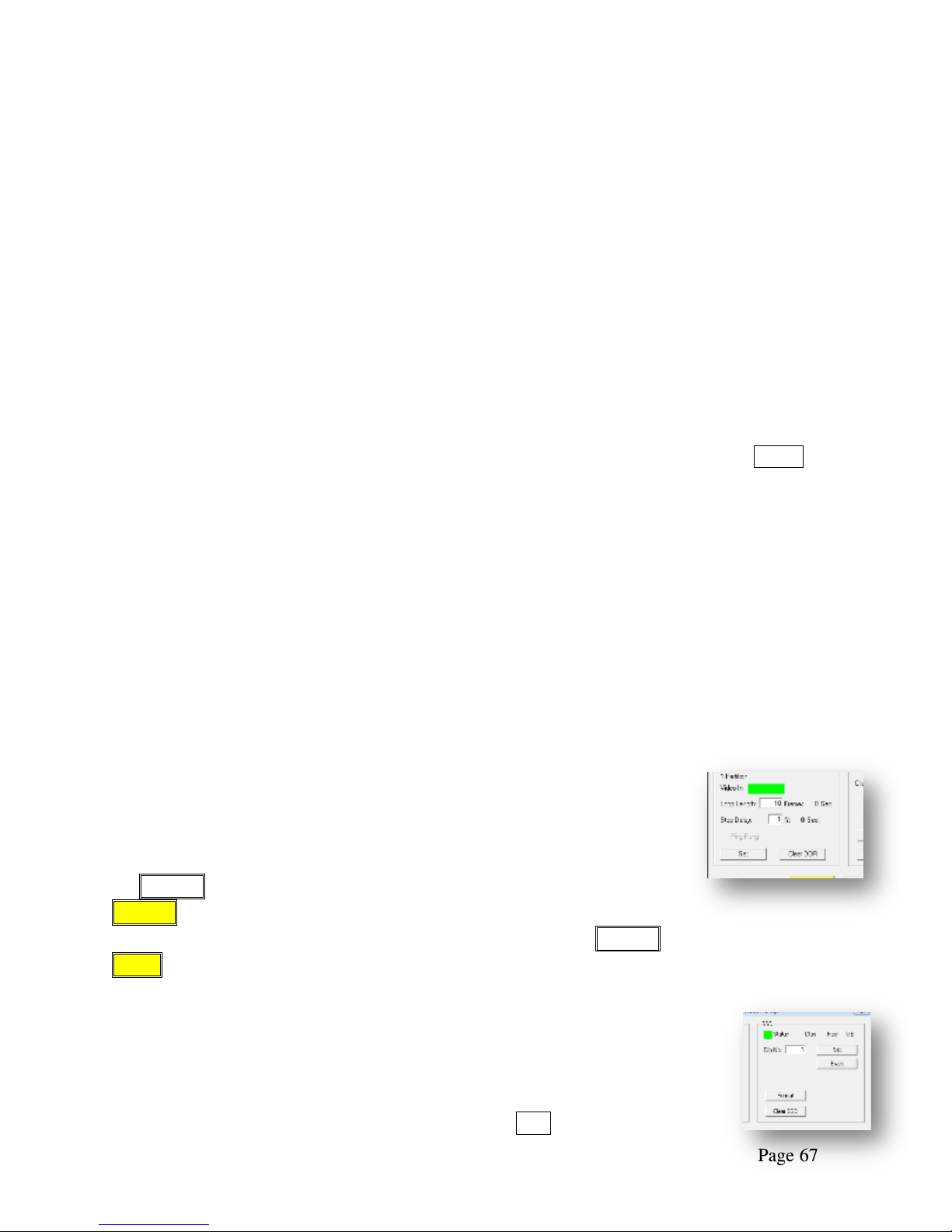
Loop length = 1200/60 = 20 seconds
Loop capacity = 6.2MB*1200 = 7,44 MB (fits in 16GB DDR with 2 partitions)
Pre-Event Time Recorded = 840/60 = 14 seconds
Post Event Time Recorded = (1200-840)/60 = 6 seconds
If a value of 00% is entered, the system is set to Event DDR/SSD mode and EVENT mode can no
longer be selected on the main form.
7.6.5.3 PING-PONG
Ping-Pong mode is a DDR EVENT record mode and is only available when the DDR is set to two
partitions.
In Ping-Pong mode, one partition is active and one partition is idle. When an Event record is
started, video is recorded in a loop to the active partition. When an event marker is received,
recording continues as specified by the stop delay. The active partition immediately begins to
record in a loop waiting for the next event trigger. When the next event is triggered, recording will
continue until the stop delay specification is met. At this point the 6520 is in stop mode and two
event clips, one in each DDR partition, is present. By selecting a playback partition, either clip
may be played back. The currently active partition may also be saved by clicking the SAVE
button.
If Auto-Save has been set, ping-pong can continue until the capacity available in the SSD is
exhausted. With Auto-save, the clip captured by the active partition is automatically saved to
SSD in the background while the other partition records in a loop until the next event trigger.
This sequence will continue to ping-pong between the DDR partitions until a stop is invoked or the
SSD exhausts free capacity.
Ping-Pong is not available when Event Mode is DDR/SSD or Continuous or the stop delay is set to
00%.
When recording stops, a SAVE to SSD operation starts automatically and the idle partition
becomes the active partition.
7.6.5.4 Clear DDR
Clear erases all clips recorded in the DDR3 and sets the DDR to one (1)
partition. Any event modes or other set up related to the DDR3 are
restored to the factory defaults.
Clear performs the overwrite operation described in paragraph 3.3.8.1
DDR3 CLEAR beginning on page 17. While Clear is being performed,
the CLEAR button is flashes yellow twice per second. When complete,
CLEAR is displays solid yellow. The button returns to normal after any
other operation is imitated (e.g. format, play, stop, record, etc.). CLEAR is only available from
STOP.
7.6.5.5 Select a clip
Clips recorded to the SSD are indexed by the 6520 in a sequential series of
numbers. The clip number is not the file name. The file name itself can be
viewed from the Status Screen.
When a clip number is entered in the text box and the SET button is clicked,
6520 Inserter-Recorder Operation Manual Page 67
Page 75
FORMAT is NOT a CLEAR or WIPE disk from
a data security perspective. The clip data is
still present, only the directory data
necessary to access it is cleared.
that clip on the clip list becomes the CURRENT CLIP. The format for clip number is nn and can
range from 01 to the last clip number previously recorded on the SSD.
After this selection is made, playback will refer to this clip. If one chooses to record with a
non-zero value entered, it will initiated an overwrite of the CURRENT clip. A confirmation of
overwrite will be given before new clip data is captured.
7.6.5.6 ERASE A CLIP
The active clip may be erased by clicking on the ERASE button. A confirmation form will appear
that confirms ERASE or CANCELs the erase operation. If erase is executed, the space consumed
by this clip becomes available for new video recordings. A change in the Free Capacity shown in
the SSD frame of this form will change to reflect the capacity returned to free space. Erasing a
clip may cause the re-index of clips to clip numbers. Be sure to recheck the clip list for any
operation after erase.
7.6.5.7 FORMAT
The FORMAT button will format (or reformat) and SSD. A confirmation form will appear that
confirms FORMAT or CANCELs the format operation. If format is executed, all video
recordings will be deleted from the SSD and will not be available or recoverable. During a format,
the FORMAT button will become yellow until complete. On completion, the free capacity will be
the full capacity of the SSD, typically 960 GB.
Warning
7.6.5.8 CLEAR SSD
Performs the erase operation described in paragraph 3.3.8.2 SSD CLEAR beginning page 17.
While Clear is being performed, the CLEAR button is flashes yellow twice per second. When
complete, CLEAR is displays solid yellow. The button returns to normal after any other operation
is imitated (e.g. format, play, stop, record, etc.). At the end of SSD clear, the SSD will be
unformatted. In order to use this SSD for recording operations, a FORMAT will be required.
CLEAR is only available from STOP
7.6.6 SDI Switch
An SDI video switch is included for the switched SDI output to select between
presenting the output of the record channel or the output of the playback channel.
.
6520 Inserter-Recorder Operation Manual Page 68
Page 76
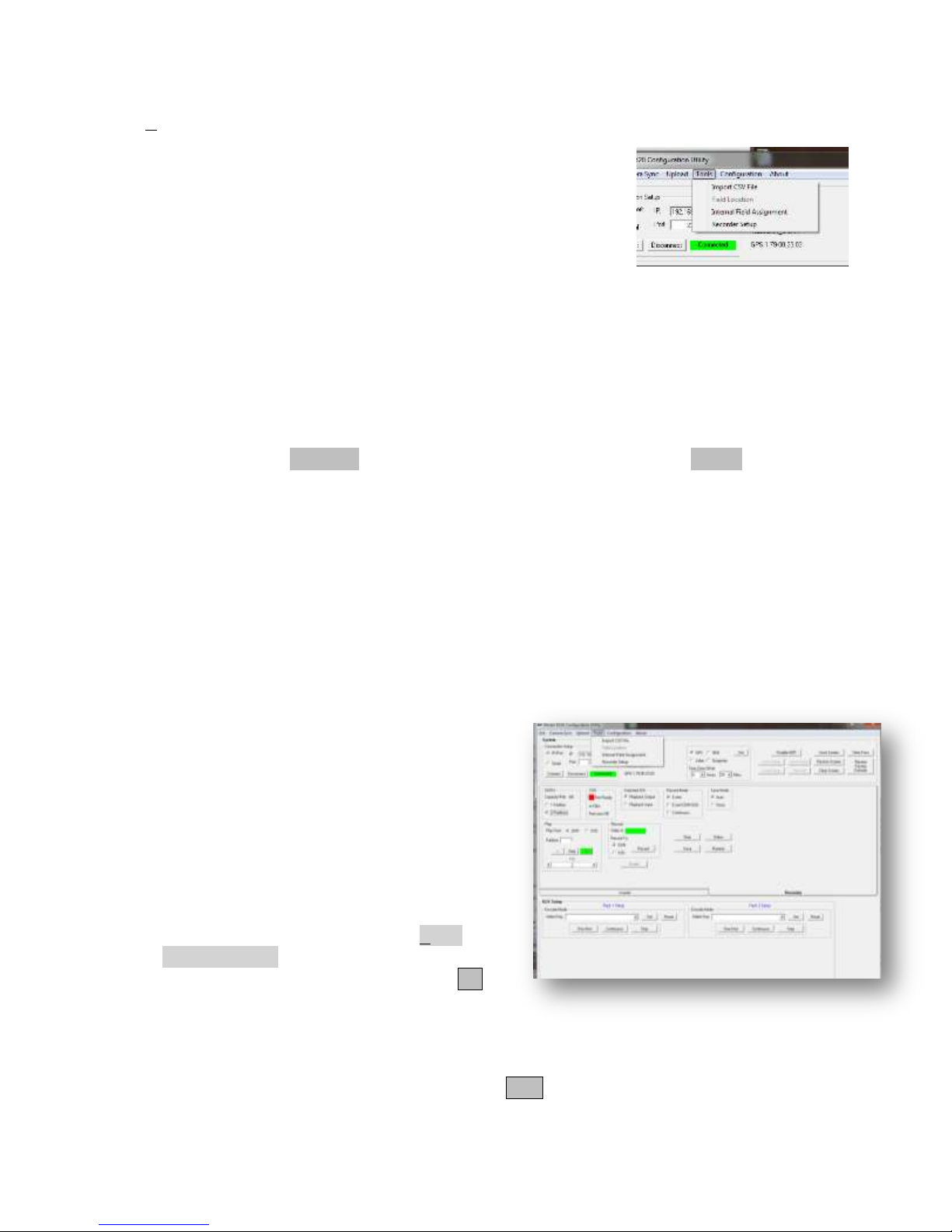
7.6.7 KL metadata
The Tools menu facilitates the import of a key in the form of a CSV file. The ITS KLV Software
Toolkit (see page 115, About the KLV Metadata Toolkit for details)
provides a KeyTemplate© with which a user may design a key
having up to 64 independent fields of information. Once completed
and a key number is assigned, it may be exported as a CSV from the
KeyTemplate©. The CSV is then ready for import by this GUI.
Import is a simple process click on Import CSV File from the
menu, find/choose the file and open it. If imported successfully, the
GUI will provide a status form stating so.
After importing a CSV file, a key file is created by the GUI and is used in a number of subsequent
options.
Generally the steps are these.
Assign (click) the channels (record, playback) to which you wish to apply the following steps.
If you are recording metadata data, this is inserting metadata packs into the Record Channel HD-
SDI video stream. The Metadata mode of the record channel is always set to Write.
7.6.7.1 Record Metadata- No Monitoring (Record Channel Metadata Write)
If you wish to only transport and record metadata with a metadata pack simply assign a key to a
pack. When the key is received, at the 6520 Ethernet interface, the content will be inserted into the
assigned pack (1 or 2) on the next received video frame. This will be a part of the video data
recorded to the DDR or SSD.
7.6.7.2 Record Channel Metadata Write with monitoring
To monitor what data is being inserted in the record channel SDI video stream use the playback to
extract the metadata content and overlay what data you want to monitor. While recording the
playback channel is in live monitor mode and
receives the same video being recorded to the DDR
or SSD. The playback channel is set to read
metadata. The steps are
1. Select the playback channel.
2. Set the key and the pack number to read.
3. Then decide what fields (all or a selected
set) are to be decoded and displayed.
4. Set the row and column location to place
the filed on the video frame.
Steps 2 and 3 are accomplished from the Tools
menu, Field Location selection. When clicked,
you must select a key from the dropdown and Set
it. This defines for the GUI what key definition is
to be used. When this is successful, the first key
field and its label (entered in the KeyTemplate© are shown in the Description text box. If you
wish to display this field, select the start (column) and Line number desired. If you do not wish to
display this field, leave the start/line blank and click Next. The next defined field of the key will
be shown in the Description. Continue this process until each field desired to be displayed is set.
6520 Inserter-Recorder Operation Manual Page 69
Page 77
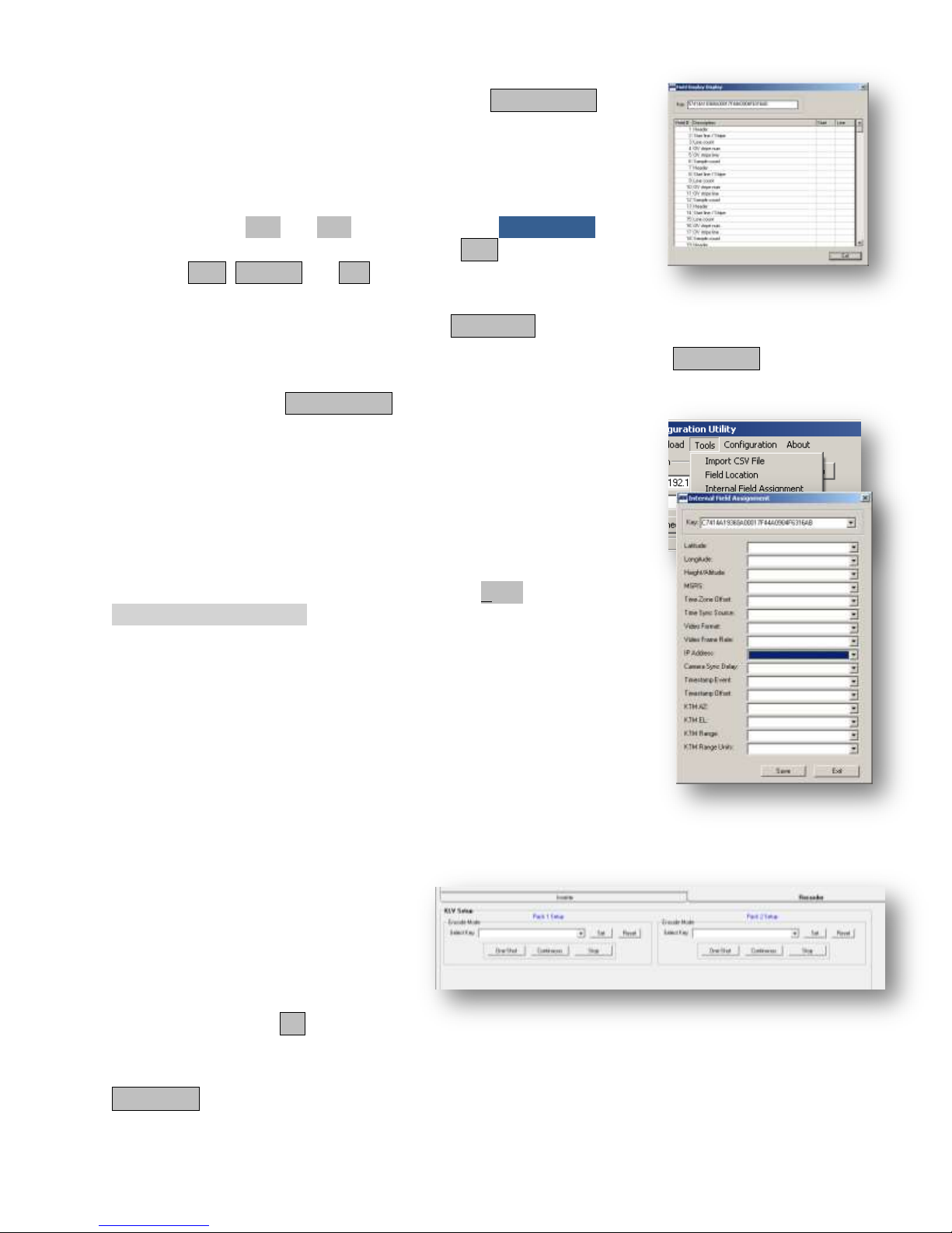
If you wish to see/review your field settings, click Display Setup.
A new form will open that will list all fields defined for the key and
show the start (column) and line numbers selected for display in the
video frame. Fields with no entries for Start and Line will not be
displayed.
You may edit the Start and Line by returning to the FieldDisplay
form and stepping through the fields using the Start (goes directly to
field one) Next, Previous and End (goes directly to the last defined
field) buttons.
When satisfied with the display design, click Save Setup.
If you have previously created a display design for this key, you may click Load Setup and a list of
files having the key number will be shown from which to select. To be sure you have the correct
display design, use the Display Setup function. You may edit a
loaded setup, edit it and save it do a new file name (rather than
overwrite it) thereby quickly creating variations on a display design.
7.6.7.2.1 Write Internal Fields (Record Channel Function)
Depending on the options integrated into the 6520 and whether
internal field byte sizes formats and offsets were defined in the
currently set key of the record channel, one may now assign the field
data to be inserted into the key data itself. This is accomplished by
first selecting the record channel. Then from the Tools menu,
Internal Field Assignment (see 9.2 KLV Pack Internal Insertion Fields
page 102 for details) submenu item. When selected, a list of available
internal fields is presented which you may assign to compatible key
field numbers. It takes a bit of bookkeeping, but when done correctly,
data that is internally available to the 6520 will automatically be
updated and integrated with the incoming metadata blocks as defined
by the key design.
7.6.7.3 Starting Transport (metadata write in record channel)
After these setup steps are complete as needed, the actual process of
writing metadata packs requires the KLV Setup. Select the Record
channel.
Assign the key desired by selecting
from the drop down menu (at least the
CSV import must be accomplished for
a key to be shown in the drop down
menu.).
When the desired key name is shown
in the dropdown click Set. This
assigns the key to the pack in which the key is set. That is all that is needed to be ready to start
accepting metadata and inserting into the pack. Metadata write can be continuous or one-shot.
Continuous means that the last metadata received will be written to every incoming HD-SDI
frame. This state is independent on whether the system is monitoring data or not.
6520 Inserter-Recorder Operation Manual Page 70
Page 78
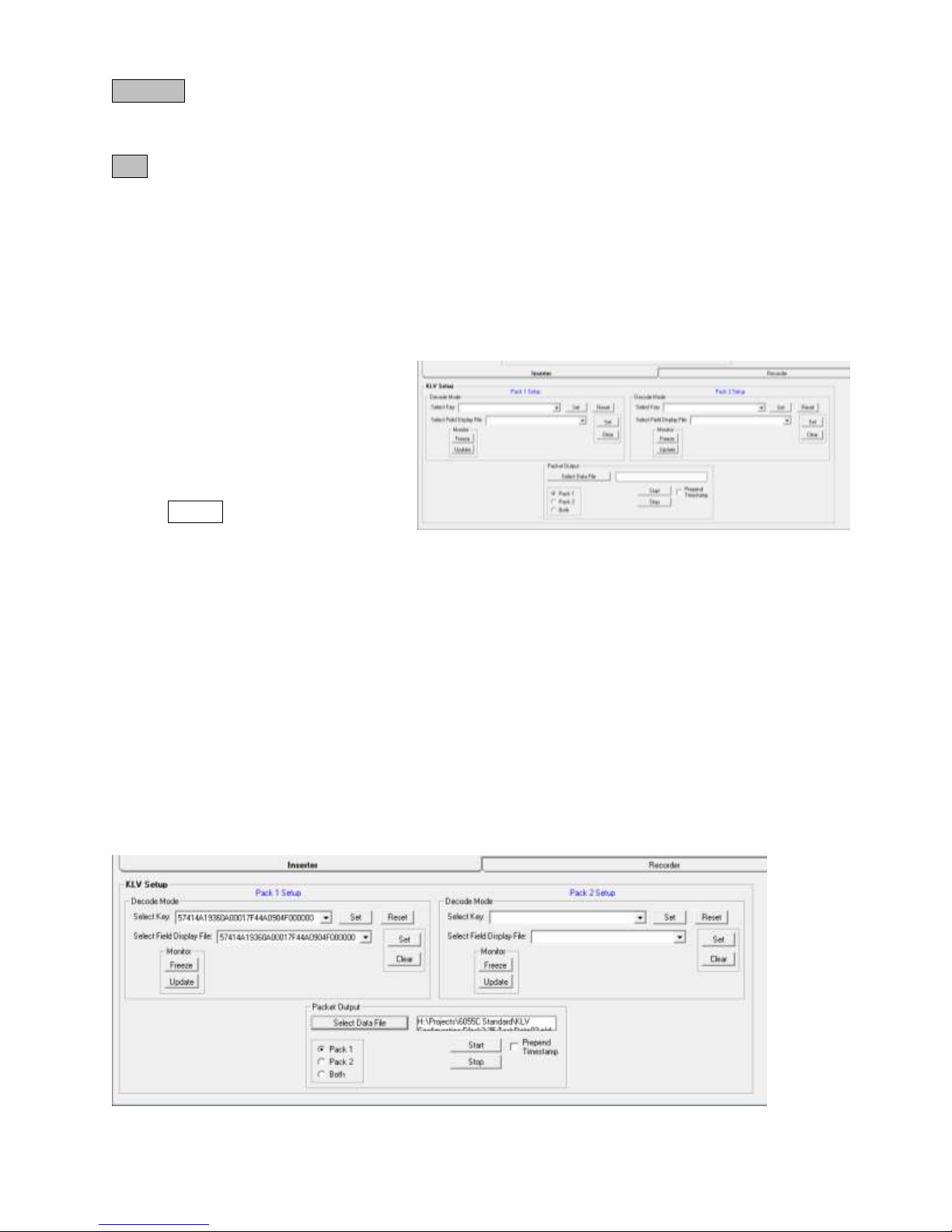
One-Shot means that the only time a new metadata pack is written to the incoming HD-SDI video
stream is when new data is received from the interface or data changes in the assigned internal
fields, if any.
Stop ceases writing metadata packs.
7.6.7.4 Display/Extract Metadata
The Playback Channel of the 6520 is used to display and/or extract previously written metadata.
Metadata is previously written by the record channel during record, or restored from the clip data
during playback. The playback channel may be used to monitor what KLV metadata is being
recorded as a live monitor function or to display metadata previously recorded.
The following steps describe how to display metadata in the Playback Channel.
1. Select the 6520 Inserter Tab
and click to set the Playback
Channel.
2. In the KLV Setup frame, select
a key and select a field location
file
3. Start display by clicking on
Update
4. If you wish to extract the data
to a file on the host computer, set a file name and extraction modes.
Completing these steps correctly will cause data to be overlaid on the playback video HD-SDI
stream. The HD-SDI stream may be the live monitor stream (SDI switch set to use the record
channel as the input to the playback channel), or the DDR3/SSD (SDI stream during playback).
Text color and font will be that selected for the playback channel previously. Data will be updated
at the at the video frame rate.
Correspondingly, if extracted to a file, the pack data will be sent via Ethernet to the file where each
frame‟s data is a record. The record may or may not be pre-pended by the frame‟s time stamp
(microseconds since January 1, 1970) for later exact correlation to the imagery itself. Each record
contains information identifying the source channel, pack number and key in a header record.
7.6.7.5 Metadata display/extract setup
When the 6520 Inserter Playback channel is selected the KLV frame appears as shown below.
6520 Inserter-Recorder Operation Manual Page 71
Page 79
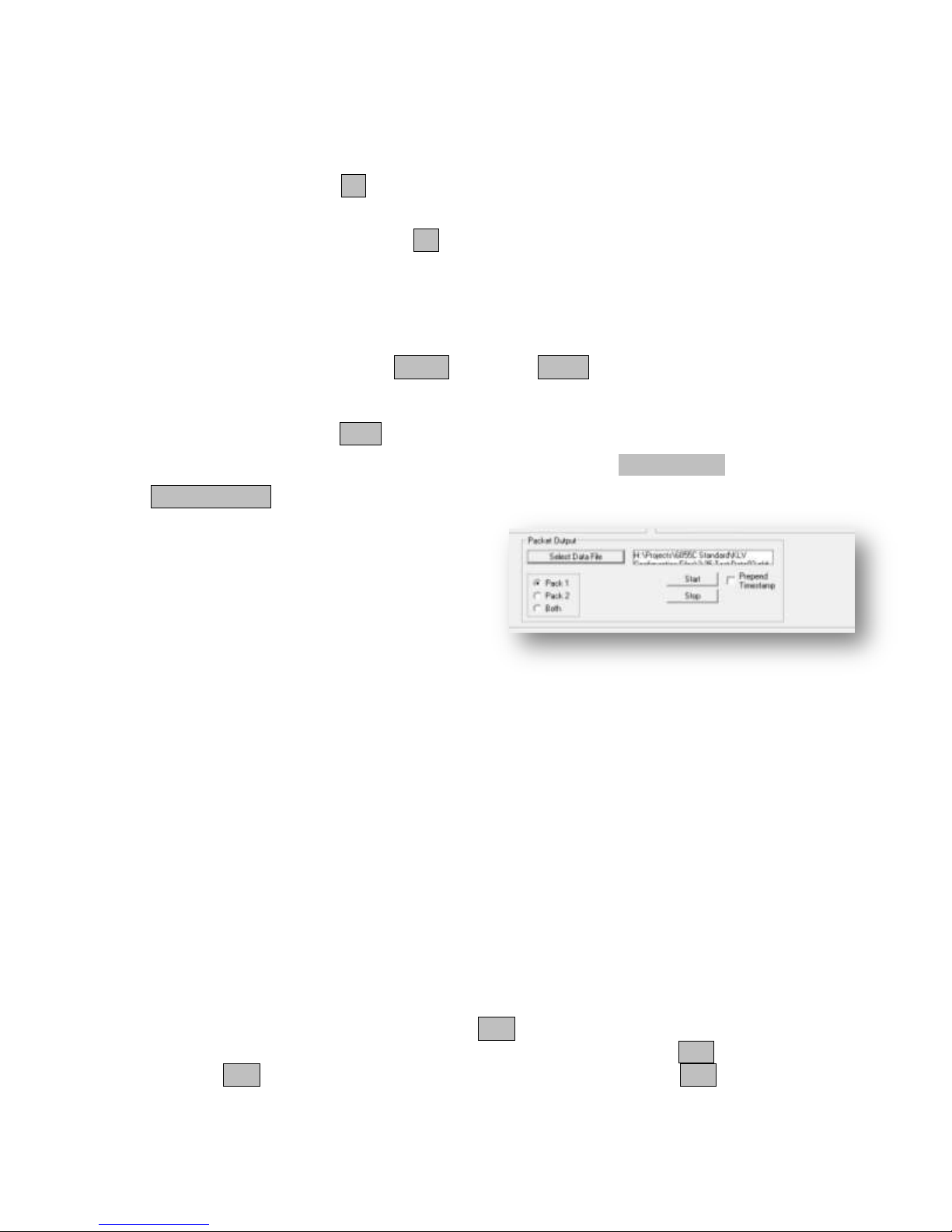
As you can see one can choose to display pack 1, pack 2 or both (assuming both are present).
Select a key by clicking on the Select Key drop down. Key numbers will appear in the dropdown
if keys have been previously imported and the GUI configuration has been set to the file location
of these files if necessary (see 7.6.8 GUI Configuration page 73).
To start the process select and Set a key. This is the minimum requirement. With only this
selection you may simply extract metadata as records to a file without overlay on the video itself.
To overlay data on the video, select and Set a field display file.
This is the “decoder ring” and display specification. These two elements tell the 6520 how to
parse the data (V content of the KLV pack) read from the pack, how to format it (scale, locate
decimal places or simply interpret as ASCII characters and where on the video frame to overlay
the text.
The Monitor of the GUI frame starts, Update, and stops, Freeze, the overlay update. Overlay of
metadata is static in that once overlaid the last data overlaid remains whether new data is received
or not or whether new metadata packs are received or not. The metadata display is only cleared
from the video frame with the Clear button.
Extracting data to a file is accomplished from this same form in the Packet Output frame.
First Select Data File. This may be a new file
or existing (overwrite). It may be any valid
Windows© file name. Select whether is
desired to include the data of pack 1, pack 2 or
both in the file. The record header will contain
the pack number for each record. A separate
record is created in the file for each pack.
Choose whether to prepend the time stamp
(check box). If you do prepend the time stamp,
the 9-byte metadata timestamp is included in the header for each record. This may be parsed and
is interpreted in accordance with the MISB 0605.3 metadata timestamp for the corresponding key.
Essentially, the first byte is a status byte indicating whether the time was synchronized to a time
standards (e.g. IRIG B, NTP or GPS). The remaining 8 bytes are the number of microseconds that
have transpired since January 1, 1970. The timestamp is extracted from the frame; therefore this
record and the timestamp of the actual video frame will match exactly to the microsecond. This
may be useful for later analysis.
The ITS Software Toolkit provides a utility GUI called KeyRead© that may be used to parse and
display field data. For this to operate, the KeyRead© can (must) import the same key CSV file.
Then open the extracted file. The KeyRead© will display the header information (channel, pack,
time in microseconds) and list the field names and associated data as extracted.
ITS Software Toolkit includes source code for the KeyRead© GUI to provide a programming
model that may be freely used to create data parsing and analysis code for your own use or to be
integrated with software of your own design and application.
Once all of these parameters are set simply click Start and the 6520 GUI will create the file or
append to the existing file extracted metadata (V content plus header). The Stop button will close
the file. Click Start again will reopen the file and append new records until Stop is clicked.
If no packs are present that have the correct key number in any one frame or all frames, no record
6520 Inserter-Recorder Operation Manual Page 72
Page 80
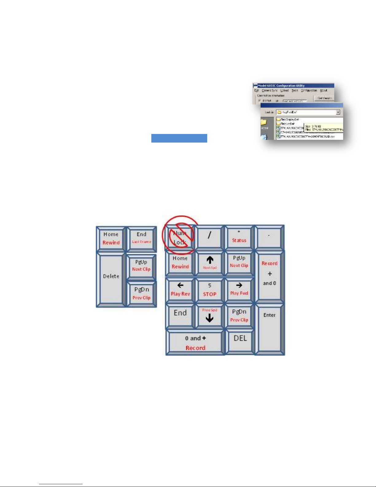
will be added to the extraction file. Missing records or skipped frames can be detected by
evaluating the time stamps.
While extracting data to a file, a status will appear under the Prepend Control indicating the
number of seconds file extraction has been active.
7.6.8 GUI Configuration
If the location of key files is not where the GUI was originally
installed on the host computer, you may redirect where the GUI
seeks these files using the configuration option.
When selected, the GUI will open a Browse For Folder form with
which you may find the desired KFD folders as exemplified on the
right.
7.7 Recorder Controls via Keyboard
When a PC is connected to the 6520 via the GUI (See 7.4 Graphical User Interface (GUI) Utility.
Page 51) or when connected to the web server through a browser (see 7.3 Webserver page 34), the
keyboard number pad (in non-NumLock mode) or the cursor arrow keys may be used to initiate
many recorder controls. The diagram below outlines the key/function mapping.
The functions mapped to these keys operate in an identical manner as the equivalents found in the
webserver or GUI.
To start a recording, the 0+Enter Key must be pressed simultaneously. This action will create a
new clip on SSD if SSD is the record to device. If DDR is the record to device, record will
overwrite the previously recorded clip of the current partition.
Last Frame sets the playback to the last frame of the current clip. Only functions in STOP. Play
is the only play option from the last frame.
Rewind sets the playback to the first frame of the current clip. Only functions in STOP. Play is
the only play option from Rewind.
6520 Inserter-Recorder Operation Manual Page 73
Page 81

PgUp/PgDn (any of these) will advance to the next clip (PgUp) or previous clip (PgDn) on the
current playback device (DDR or SSD). Only functions in STOP.
or will set through playback speeds from stop as Step>1x, 2x, 4x, 8x,16x, 32x or from
stop/step <1/32x, 1/16x, 1/8x, 1/4x, 1/2x. When already in play, > will increase speed to 32x and
< will decrease speed (skipping step) to 1/32x. Stop will set speed to step (single frame). Speed
may be changed while playing (no change in direction).
Initiates Play in the direction indicated. When in speed is step, the next/previous frame is
presented to the HD-SDI output. Direction can be changed during play (no change in speed).
* Toggles the green status screen on and off. This can be set any time (during stop, play or
record); however the status screen only appears when in STOP mode.
.
6520 Inserter-Recorder Operation Manual Page 74
Page 82
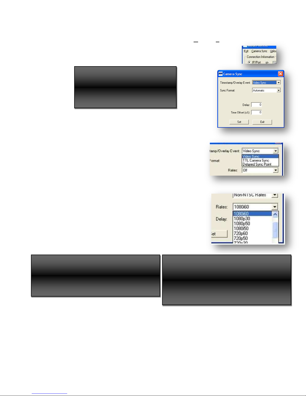
Set the camera to ALWAYS generate
and SDI output when attempting to let
Setting the format manually attempts to force the
video source to comply with the format selected.
When a sync setting is set, output video from the
camera and the 6520 may temporarily be
interrupted until the camera adjusts for the change
in sync timing and the 6520 can resynchronize with
7.7.1 Camera Sync (-CS Option)
When this option is present, the GUI will offer a new menu item, Camera Sync.
Selecting this menu item will open a form that lets one set a variety of important
camera sync parameters.
Warning
the 6520 automatically set sync format.
7.7.1.1 Timestamp Event
The Timestamp Event setting determines on which event the 6520
collects time. When Video Sync, time is collected at each EAV
line 1, on TTL Camera Sync time is collected at the leading edge
of the TTL sync and when the Delayed Sync Point, time is
collected on the 0H point of the outgoing tri-level sync (TLS).
7.7.1.2 Sync Format
The Sync Format permits one to choose NTSC (29.97, 30, 50,
59.94, and 60). The TTL sync output is active for all rates.
7.7.1.3 Rates
When Rates is Off, the format and frame rate of the output camera
sync are set to that which is present at the record channel video
input HD-SDI stream. When anything other than Off is selected,
the format of the TLS is adjusted to match the setting.
Warning
This may not work and may result in no video.
NOTE
6520 Inserter-Recorder Operation Manual Page 75
Page 83
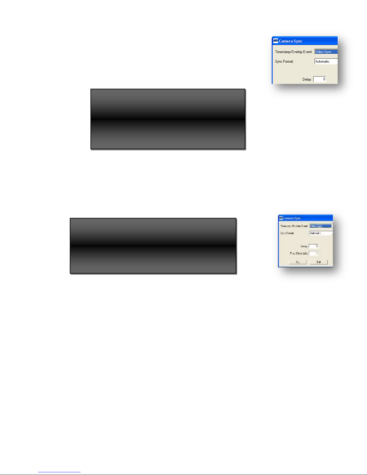
When using the Time Offset latency measurements will
be directly affected by setting this value of the
measuring channel does not have the same offset
value.
When setting a delay, it changes sync timing to the
camera. This may cause the video from the camera
to be interrupted while it adjusts to the change in
sync timing and the 6520 resynchronizes with the
7.7.1.4 Delay
The Delay setting is a value in microseconds. When non-zero the 0H point
of the TLS and leading edge of the companion TTL sync of the selected
channel(s) are shifted (delayed) x µsec with respect to GPS, NTP or IRIG
time.
In order to start these changes, the Set button must be clicked.
NOTE
7.7.1.5 Time offset
The Time Offset will add the number entered to the time collected with the instructed
Timestamp/Overlay event. Units of this value are microseconds offering the operator offsets of 0
to ±20,000 µseconds in 1 second steps. When SET is clicked, the Delay, Sync Format and
Timestamp/Overlay Event commands are sent to the ACTIVE channels.
NOTE
6520 Inserter-Recorder Operation Manual Page 76
Page 84

8.0 PROGRAMMING/SETUP
All functions are accessible via the keyboard in rack mount versions. All keyboard functions may
also be controlled remotely over the Ethernet port. The programmable functions are:
Enabling and positioning of the time message
Enabling, sizing and positioning of movable crosshair
Enabling and sizing the Boresite reticle (crosshair)
Enabling Metadata read or write
KLV option pack parameters (option)
a. Internal fields to be integrated
b. Fields to be displayed in monitor mode
c. Fields to be displayed in read mode
d. Key field formats and locations
e. Turn on/off extraction of KLV data to Ethernet port
Display and positioning metadata time
Naming and positioning of the event messages
Composition of inserted annotation
Individual selection of graphics and annotation color.
Setting the Time Zone Offset (GPS option only)
Setting of Dynamics Mode (GPS option only)
Setting the Ethernet port IP address, port, mask and gateway
Setting RS232 baud rate
Setting video display insertion level (front panel control only)
Resetting to factory defaults
Reboot the system
6520 Inserter-Recorder Operation Manual Page 77
Page 85

<shift>"key_name"
Shift key is held down while designated key is pressed. i.e., <shift>F1
indicates that the SHIFT and F1 keys are pressed simultaneously.
<alt>"key_name"
Alt key is held down while designated key is pressed.
^"key_name"
CNTL key is held down while designated key is pressed
{UP}
Designates the "Up Arrow" key.
{DN}
Designates the "Down Arrow" key.
{RT}
Designates the "Right Arrow" key.
{LF}
Designates the "Left Arrow" or Backspace key.
KB Equivalent
HEX
BYTES
DESCRIPTION
Group
Command
Class
Survives
Power
Cycle
<ALT>Fx
91H-
9nH
1
F1 sets record, F2 sets playback to enable
annotation formatting. Selecting a particular
channel adds this channel to the list of selected
channels and facilitates control and formatting of
both channels at once.
Active
Channel
Selector
Global
Operator
N
<SHIFT>F11
8BH
1
Selects BOTH channels and facilitates controlling
and formatting both the playback and record
channels of the system at once. This only applies
to text and graphic functions. Metadata functions
are different for the playback and record channels.
Active
Channel
Selector
Global
Operator
N
8.1.1 PROGRAMMING CONVENTION
The Model 6520-nxHD command set is shown using keyboard equivalents control uses special
control codes to allow the user access to specific operational functions. The HEX column
provides the value of the key combination such as <SHIFT>F11 is HEX 8B.
The convention for the following tables is:
8.1.2 REMOTE CONTROL FUNCTIONS
The table below defines the keyboard commands used for local programming and the equivalent
remote control commands available for the 6520-nxHD models. Controls that are channel specific
are specified as Record (1) and Playback (2).
In the Survives Power Cycle column, of the table below
1. N signifies that after a power cycle, this setting returns to the factory default.
2. Y signifies that a ^O command will save this setting to FLASH and will be restored to this
value after a power cycle or reboot of the system.
The default mode of the 6520 after power up or reboot is PLAY; STOP.
6520 Inserter-Recorder Operation Manual Page 78
Page 86

KB Equivalent
HEX
BYTES
DESCRIPTION
Group
Command
Class
Survives
Power
Cycle
<SHIFT>F12
8CH
1
Deselects both the record and playback channels.
Active
Channel
Selector
Global
Operator
N
^YSFn
19H
4
Sets Screen Format, 0=first 32 lines, 1=middle 32
lines, 2= last 32 lines, 3=split 16/16; this command
only has effect in 1080 with small characters. At
2H and/or 2W characters the system fills the screen
as it does at lesser line counts (e.g. 720, 480).
Admin
Channel
Specific
Y
^Gn
07H
2
Set date display mode where: n=0 Gregorian, n=1
Julian
Admin
Global
Operator
Y
^O
0FH
1
Saves displayed annotation text of both channels to
Non-Volatile RAM. Only applies to text and local
time functions.
Admin
Global
Operator
N
^P
10H
1
Restores saved annotation text to both channels.
This occurs automatically when the unit is turned
on. Only applies to text and local time functions.
Admin
Global
Operator
N
^Tyydddhhmmss
<CR>
14H
13
Set time. Time is entered from left to right,
punctuation characters are jumped over, and error
checking is done on a character by character basis.
Invalid entries are not accepted. If there is an error
in the entered value, press the ESC key and try
again. When the complete time is entered correctly,
press ENTER. The time will be set the moment
that the ENTER key is pressed. TIME cannot be
set manually if currently locked to GPS, NTP or an
IRIG input signal.
yy=year (00-99), ddd=Julian Days (001-366), hhhour(0-23), mm=minutes(00-59), ss=seconds (00-
59).
Admin
Global
Operator
N
^YDMn
19H
4
Set Dynamics Modes, n=1 to 5
See 3.2.3.1 GPS Dynamics Mode page 6
Admin
Global
Operator
Y
6520 Inserter-Recorder Operation Manual Page 79
Page 87

KB Equivalent
HEX
BYTES
DESCRIPTION
Group
Command
Class
Survives
Power
Cycle
^YNSnnn.nnn.nnn
……nnn.nnn<CR>
19H
6-57
Network values may be changed with this
command. The values changed may be the IP,
Gateway, Subnet Mask and Port. The format after
^YNS is:
iii.iii.iii.iii[,ggg.ggg.ggg.ggg][,mmm.mmm.mmm.
mmm][-ppppp]<CR>
The IP address, gateway address and subnet mask
addresses data must be comma separated as shown
in the template above. Empty fields (comma only)
are allowed which will then use their current
values. The Port Number field is prefaced with a '' and may be specified by itself (i.e. no IP, GW,
NM fields (or commas!) are required). Omitting
the Port Number field off uses a previously set port
value.
[] show elements that are optional.
The format specifics are:
IP address: "iii.iii.iii.iii"
gateway address: "ggg.ggg.ggg.ggg"
subnet mask: "mmm.mmm.mmm.mmm"
port number: -ppppp (must be preceded by a "-")
iii, ggg, and mmm range from 0..255.
ppppp ranges from 0..65535.
When any of the network setting values are
changed either from the front panel or this external
command, the 6980G-HD will automatically
reboot. Any previously opened windows socket
should be closed and reopened with the new
address to resume normal control and
communications after reboot is complete
(approximately 5 seconds).
An <ESC> entered any time after ^Y and before
the <CR> aborts the command.
Admin
Global
Operator
Y
^YRB<CR>
19H
4
Reboot the system
Admin
Global
Operator
N
^YSSn
19H
4
Enables/disables the display of the status screen on
the SDI output where n=0 is enabled (default) and
n=1 is disabled.
Admin
Global
Operator
N
^YTSn
19H
4
Set time source where: n=0 is GPS, n=1 is IRIG. It
is not necessary to select NTP as it is a fallback if
no lock is achieved with either IRIG B or GPS.
Admin
Global
Operator
Y
^YTZ±hhmm
19H
8
Enhanced Time Zone Offset command permits
setting to a resolution of one-quarter hour.
Where: hh=0 to 12, mm = 15, 30 and 45 only.
Sign (±) must be present.
Admin
Global
Operator
Y
6520 Inserter-Recorder Operation Manual Page 80
Page 88

KB Equivalent
HEX
BYTES
DESCRIPTION
Group
Command
Class
Survives
Power
Cycle
^YVQ
19H
3
Version Query command.
Return = a string ; Main Version (cyclone
firmware)”,” Annotator Version”,” GPS <CR>
version
Admin
Global
Operator
N
^Z±nn
7AH
4
Set time zone offset. Where: ±nn = positive or
negative offset. This function is active only when
GPS is used as a time reference. nn=hours (00-12)
This is a legacy command to retain compatibility
with older products.
Admin
Global
Operator
Y
^YSW2x
19H
5
Set the playback output SDI switch to the input or
output of the playback channel where:
2= the playback channel
x = 0 is playback output (default) or 1 = playback
input
x=9 sets the current switch state as the default.
Note: all data are ASCII
Admin
Playback
Channel
Y
^YTEs
19H
4
Set the event on which the time is collected for
time stamping and video overlay for the active
channels
Where: s=0 Video sync (output from the camera,
DEFAULT), 1=TTL camera sync (leading edge),
2=The delayed sync point.
This command is only active with the -CS option.
Camera
Sync9
Record
Channel
N
^YTO±mmmmm
19H
9
"Enters an offset (±mmmmm) in µsec to the time
collected for timestamping for the active channels.
Where:
±mmmmm is 0 to ±20000 microseconds of
offset. Sign must be specified."
Camera
Sync
10
Record
Channel
N
^YSOA<CR>
19H
5
Sets the tri-level sync output format to match the
format decoded from the incoming HD-SDI
channel(s) enabled (active). The TTL sync will
occur on each frame detected. This command is
only active with the -CS option.
Camera
Sync1
Record
Channel
N
^YSOrrr<CR>
19H
7
Sets the sync rate on to a non-standard frame rate,
that is 010=10fps, 100= 100fps, 150= 150 fps and
200=200 fps. When this command is received the
TLL sync follows the frame rate set. The tri-level
sync is disabled for the selected channels. This
command is only active with the -CS option.
Camera
Sync1
Record
Channel
N
9
10
Requires the “CS” option which provided TTL and Tri-level Camera sync outputs for each channel
Requires the “CS” option which provided TTL and Tri-level Camera sync outputs for each channel
6520 Inserter-Recorder Operation Manual Page 81
Page 89

KB Equivalent
HEX
BYTES
DESCRIPTION
Group
Command
Class
Survives
Power
Cycle
^YSOrrrfff<CR>
19H
10
The command sets the format (fff) and frame rate
(rrr) of the tri-level sync for all active channels.
TTL sync follows the frame rate (rrr).
Values of formats are 72P,80I,80P for 720p, 1080i
and 1080p respectively. 72P and 80P values can be
paired with frame rates of 029,030,050,059 and 060
representing 29.97, 30, 50, 59.94 and 60 fps
respectively. 80I may be paired with 029 and 30
only.
Note: Tri-level sync is disabled when
ffff=010,100,150 or 200.
This command is only active with the -CS option.
Camera
Sync1
Record
Channel
N
^YTLmmmmm
19H
8
Sets a delay between the occurrence of the selected
time reference one-second tick and the camera sync
timing. The value of mmmmm is in microseconds
and instructs the system to offset synchronization
(delay) precisely this amount for all active
channels. Both the tri-level sync (if enabled) and
TTL sync are delayed together for the currently
selected channels when this instruction is sent.
This command is only active with the -CS option.
Camera
Sync1
Record
Channel
N
^Fab
06H
3
Select boresite crosshair format and color for all
active channels. a=format where 0= disable, 1=full
screen, 2=small and 3=medium. B = color where
0=black, 1=white. Use ^YXF instead. This is a
legacy command for backward compatibility with
controls developed for 6055B models.
Crosshair
Active
Channel
Specific
N
^YXFabc
19H
6
Set boresite/crosshair format and color for all
active channels.
a=0 boresite, a=1 crosshair
b=0 disable, b = 1 full screen, b = 2 small, b=3
medium.
c= 1 to 8 for color select where 1=black, 2=white,
3=red, 4=green, 5=blue, 6=cyan, 7=magenta and
8=yellow.
Crosshair
Active
Channel
Specific
N
^YXP±xxxx±yyyy
19H
13
Position movable crosshair for all active channels.
When setting position, it is relative to center of
screen, where the range for ±xxxx and ±yyyy is 9999 to +9999. Only available for HD models
only.
Crosshair
Active
Channel
Specific
N
^X
18H
1
Clears the annotation display and moves the cursor
to the HOME position.
Cursor
Active
Channel
Specific
N
{BS} or ^H
08H
1
Moves the cursor left one character and will wrap
around from the beginning of the current line to the
end of the previous line until the HOME position is
reached.
Cursor
Active
Channel
Specific
N
6520 Inserter-Recorder Operation Manual Page 82
Page 90

KB Equivalent
HEX
BYTES
DESCRIPTION
Group
Command
Class
Survives
Power
Cycle
{DN} or ^J
0AH
1
Moves the cursor down 1 line until the last line is
reached.
Cursor
Active
Channel
Specific
N
{END} or ^\
1CH
1
Moves the cursor to the end of the current line.
Cursor
Active
Channel
Specific
N
{RT} or ^L
0CH
1
Moves the cursor right one character and will wrap
around form the end of the current line to the
beginning of the next line.
Cursor
Active
Channel
Specific
N
{UP} or ^K
0BH
1
Moves the cursor UP one line until the top line is
reached.
Cursor
Active
Channel
Specific
N
DELETE
7FH
1
Deletes the last character entered and moves the
cursor back to the deleted character location.
Cursor
Active
Channel
Specific
N
ENTER or ^M
0DH
1
Moves the cursor to the beginning to the next line.
Cursor
Active
Channel
Specific
N
HOME
1EH
1
Moves the cursor position to the top left-most
position in the annotation field
Cursor
Active
Channel
Specific
N
TAB or ^I
09H
1
Advances to the next tab stop (4 character stop) to
the end of line.
Cursor
Active
Channel
Specific
N
^Qn
11H
2
This function is only active via the Ethernet inputs.
Turns the cursor ON/OFF, n=0 is OFF, n=1 is ON.
Cursor
(external
control)
Active
Channel
Specific
N
^AL
01H
2
Sets LATITUDE MESSAGE position to the
current location of the cursor.
Data Field
Active
Channel
Specific
N
^AN
01H
2
Position the start of the Frame Number at the
cursor location where Frame number is a count of
frames per second. Frame number is set to ZERO
at each 1 second increment.
Data Field
Active
Channel
Specific
Y
^AO
01H
2
Sets LONGITUDE MESSAGE position to the
current location of the cursor.
Data Field
Active
Channel
Specific
N
^AP
01H
2
Sets TIME PACKET MESSAGE (MISB
Timestamp) position to the current location of the
cursor.
Data Field
Active
Channel
Specific
N
6520 Inserter-Recorder Operation Manual Page 83
Page 91

KB Equivalent
HEX
BYTES
DESCRIPTION
Group
Command
Class
Survives
Power
Cycle
^AT
01H
2
Sets TIME MESSAGE field to the current location
of the cursor.
To turn off the time message, send the cursor to
the end of a line, EOL (1C hex) then this
command. It effectively places the time message
out of sight (off)
Data Field
Active
Channel
Specific
N
^AV
01H
2
Sets VIDEO TYPE MESSAGE position to the
current location of the cursor.
Data Field
Active
Channel
Specific
N
^YTRn
19H
4
Set time resolution, n=0 to 6; 0 =seconds, 1 =
tenths of seconds, 2= 10 mS, 3= 1 mS, 4 = 100 µS,
5 =10 µS, 6 =1 µS
Data Field
Active
Channel
Specific
Y
^YTQ
19H
3
Returns a string to the issuing port reporting the
temperature of the CPU and DDR3 Memory in
degrees C as “^YTQ CPU:+35C; MEM:+56C<CR>”
Data Field
Global
Operator
N
^AY
01H
2
Sets LATENCY TEST MESSAGE position to the
current location of the cursor. This function is only
active for the playback channel.
Data Field
Playback
Channel
N
^YMFF2errccc
19H
11
Playback Marker (PV). The Playback Video
marker may display (enable) or hide (disables) a
PV text field overlaid on the frame. This marker
can be used to distinguish between a live video
scene and playback when the recorded scene is
essentially the same image as the live scene.
2=equals two, the playback channel.
e =1 enable, e=0 is disable.
The position is rr (row) and ccc (column).
Data Field
Playback
Channel
N
^YMFP2errccc
19H
11
Positions and displays (enable) or hides (disables)
the metadata packet time (MISB timestamp).
This may be directed at either the Record or
Playback channels (active channel).
2=equals two, the playback channel.
e =1 enable, e=0 is disable.
The position is rr (row) and ccc (column).
Data Field
Playback
Channel
Y
6520 Inserter-Recorder Operation Manual Page 84
Page 92

KB Equivalent
HEX
BYTES
DESCRIPTION
Group
Command
Class
Survives
Power
Cycle
^YMFY2errccc
19H
11
Positions and displays (enable) or hides (disables)
the results of the Latency Test. The latency test
compares the time value extracted from the MISB
Timestamp (if present) and the local time indicated
by the internal time master. The time master may
be synchronized GPS, IRIG or NTP (when
implemented). The value is in microseconds and
is the Timestamp time minus the time master time.
2=equals two, the playback channel.
e =1 enable, e=0 is disable.
The position is rr (row) and ccc (column).
Data Field
Playback
Channel
N
^YMFE1errccc
19H
11
Positions and displays (enable) or hides (disables)
the Event Marker, . This command also
determines whether the event marker appears
before or after an event is triggered (discrete,
command or button).
1=one, the record channel
e =1 enable and show before event, e=2 enable and
show after the event, e=0 is disable.
The position is rr (row) and ccc (column).
Data Field
Record
Channel
Y
^YMFLnerrccc
19H
11
Positions and displays (enable) or hides (disables)
the internal GPS latitude when locked. This may
be directed at either the Record or Playback
channels (active channel).
n=channel number, 0=both, 1 = RECORD,
2=PLAYBACK
The position is rr (row) and ccc (column).
e =1 enable, e=0 is disable.
Data Field
Record or
Playback
Y
^YMFNnerrccc
19H
11
Positions and displays (enable) or hides (disables)
the Frame Count. This is a 3 digit number that
begins (resets) to zero (0) on each whole second
increment from the time master. The count value
increment on each SAV (new frame) until the next
whole second increment is encountered. This may
be directed at either the Record or Playback
channels (active channel).
n=channel number, 0=both, 1 = RECORD,
2=PLAYBACK
The position is rr (row) and ccc (column).
e =1 enable, e=0 is disable.
Data Field
Record or
Playback
N
6520 Inserter-Recorder Operation Manual Page 85
Page 93

KB Equivalent
HEX
BYTES
DESCRIPTION
Group
Command
Class
Survives
Power
Cycle
^YMFOnerrccc
19H
11
Positions and displays (enable) or hides (disables)
the internal GPS longitude when locked. This
may be directed at either the Record or Playback
channels (active channel).
n=channel number, 0=both, 1 = RECORD,
2=PLAYBACK
The position is rr (row) and ccc (column).
e =1 enable, e=0 is disable.
Data Field
Record or
Playback
Y
^YMFTnerrccc
19H
11
Positions and displays (enable) or hides (disables)
the local timestamp. This may be directed at
either the Record or Playback channels (active
channel).
n=channel number, 0=both, 1 = RECORD,
2=PLAYBACK
The position is rr (row) and ccc (column).
e =1 enable, e=0 is disable.
Data Field
Record or
Playback
Y
^YMFVnerrccc
19H
11
Positions and displays (enable) or hides (disables)
the video format (480i, 720p, 1080i, 1080p). This
may be directed at either the Record or Playback
channels (active channel).
n=channel number, 0=both, 1 = RECORD,
2=PLAYBACK
The position is rr (row) and ccc (column).
e =1 enable, e=0 is disable.
Data Field
Record or
Playback
N
^YPKS1tab
19H
8
Sets the enable/disable/one-shot attribute for all or
a specific record channel
1 = record channel
t=Time pack, default is ON (1) when
system is set to write metadata
a=Accessory Pack 1 (0=Pack OFF
(default), 1=Pack On continuous, 2= Pack
once at next sync after data received)
b=Accessory Pack 2 (0=Pack OFF
(default), 1=Pack On continuous, 2= Pack
once at next sync after data received)
Note: All data after the ^YPKS header are binary.
Packet11
Record
Channel
N
^YPKFp
PARAMS
[,PARAMS]…
[,PARAMS]
<CR>
19H
Var
See
Note
1
Formats the VALUE retrieved for display as read
from the metadata in the playback channel.
p = pack number
Packet
3
Playback
Channel
N
11
Requires the “DP” option which upgrades the ITS Insertion Engine to write and read up to two additional KLV type
02 packets of the HD-SDI video stream. This option is not yet available. Contact factory for availability and price.
6520 Inserter-Recorder Operation Manual Page 86
Page 94

KB Equivalent
HEX
BYTES
DESCRIPTION
Group
Command
Class
Survives
Power
Cycle
PARAMS is in the format QOLFNMM
where:
o Q = field number; value 1 to 64.
o O= Byte offset into data v..v; value
must be <= the Length of the Value
defined in the KLV for the pack + L.
o L = number of bytes in this field; the
sum of O+L must be <= the Length of
the Value defined in the KLV for the
pack
o F = format number (1 Byte) where:
(see KLV Metadata Value Data Item Types,
page 101 for details of each data type)
0=BINARY
1=ASCII
2=UI-NZ
3= UI-WZ
4= SI-NZ
5= SI-WZ
6= UI-MAX; MM=scale
factor
7= SI-MAX; MM=scale
factor.
10= SP; left justified.
11=DP;
o N For formats 2-5, this value
specifies how many digits to move the
displayed decimal point to the left.
Range 0 to 8 Example: 1 byte
Data=255, N =2 would display 2.55
(resolution 0.01/bit).
o N For formats 6-7, this value
specifies how many fractional digits
to display (0 would be none {e.g.
359}, 5 would be 5 {e.g. 359.99999}.
Range 0-8
o MM (format 6). MM is a scale factor
for the formula MM x Data / 2E
where: Data is the value of the
specified bytes and E= 8, 16 or 24 for
1,2 or 3 byte data respectively.
Example: MM= 360, Data is 1 byte,
the maximum displayed data is
358.59375 and the minimum is
0.00000 with a resolution of
360/256=1.40625. Binary values in
Data must be left justified (e.g. 21 bit
Az input data would occupy bits
[23:3] in a 3 byte value and bits [2:0]
must be 0).
o MM (format 7). MM is a scale factor
for the formula MM x ±Data / 2
(E-1)
where: Data is the 2's complement
6520 Inserter-Recorder Operation Manual Page 87
Page 95

KB Equivalent
HEX
BYTES
DESCRIPTION
Group
Command
Class
Survives
Power
Cycle
signed value of the specified bytes
and E= 8, 16 or 24 for 1, 2 or 3 byte
data respectively. . Example: MM=
180, Data is 1 byte, the maximum
displayed data is 178.59375 and the
minimum value is -180.00000 with a
resolution of 360/256=1.40625.
Binary values in Data must be left
justified (e.g. 21 bit AZ input data
would occupy bits [23:3] in a 3 byte
value and bits [2:0] must be 0).
Note: All data after the ^YPF header are binary.
NOTE 1
6+n*7
Range =
13-64*7=
13-454 bytes
Where n=number of fields of V (1-64)
^YPKLpqqrrccc
<CR>
19H
Positions individual fields of data, as defined in the
^YPKF command, on the video display. This
function is only active for the playback channel
p = pack number ('1' or '2').
qq = field number ("01" to "64").(as
defined for the pack V)
rr = row ("01" to maximum display row).
ccc = column ("001" to maximum display
column).
Note: All data are ASCII.
Packet
3
Playback
Channel
N
6520 Inserter-Recorder Operation Manual Page 88
Page 96

KB Equivalent
HEX
BYTES
DESCRIPTION
Group
Command
Class
Survives
Power
Cycle
^YPKR2pte
19H
8
Reads and outputs to the Ethernet port the VALUE
of a key for all or the specified channel
2(two); the Playback channel
p= pack number (1 or 2).
t = 1 prepend the 9 byte (1 status, 8 time)
microsecond timestamp value to each
pack, t = 0 does not prepend this data.
e = enable (1) / disable (0) sending the
read V(s) out of the Ethernet port.
ETHERNET OUPUT
The Ethernet output format for each V will be
(19H)PKRLLiptk...k[u]v…vcc where:
LL=length of the total response to follow
e.g. sum(i+p+t+k..k+[u]+v..v+cc) ; 2
bytes
Values of LL would not be less than 19
and not greater than 262.
i =2, always the playback channel; 1 byte
p =pack (0,1); 1 byte
t=time flag where 0=not
present,1=present
k…k = key (16 bytes)
t = if specified; microsecond time stamp
data (status+time); 9 bytes
v…v = value/ pack content (1-235 bytes)
cc = 16 bit sum of all bytes calculated
from the from the 19H byte to and
including the last v byte;
The values of LL and checksum (cc) are big endian
ordered.
Note: All data after the ^YPKR header are binary.
This output is not available at the RS232 serial
port.
Packet
3
Playback
Channel
N
^YMWn
19H
4
Metadata MISB timestamp write where:
n=0 is OFF,
n=1 is CONDITIONAL WRITE. The 6520 will
write a MISB timestamp only when a MISB
timestamp is present NOT on line 9 of the
incoming video.
n=2; Always WRITE. The 6520 will write a MISB
timestamp on line 9 whether a preexisting
timestamp is present or not (overwrite).
Packet
3
Record
Channel
Y
6520 Inserter-Recorder Operation Manual Page 89
Page 97

KB Equivalent
HEX
BYTES
DESCRIPTION
Group
Command
Class
Survives
Power
Cycle
^YPKIpqexyz
19H
Sets selected fields defined in ^YPKF command as
internal data (data generated internally and replaces
external ^YPKW data automatically). This function
is active only in the record channel.
p = pack number
q = field number
e = enable/disable insertion by default
(0=disabled/external data,
1=enabled/internal data)
x = internal variable index Indexes are
defined in KLV Pack Internal Insertion
Fields page 101
y = 0; Reserved
z = 0; Reserved
Note: All data after the ^YPKI header are binary.
Packet
3
Record
Channel
N
^YPKVpqe<CR>
19H
Enable/disable selected fields defined in ^YPKI
command as internal data. This function is only
active for the record channel.
p = pack number (1 byte, '1' or '2')
q = field number (2 bytes, '01' to '64') as
defined for the pack V
e = enable/disable insertion (1 byte,
'0'=disabled/external data,
'1'=enabled/internal data
Note: All data are ASCII.
Packet
3
Record
Channel
N
6520 Inserter-Recorder Operation Manual Page 90
Page 98

KB Equivalent
HEX
BYTES
DESCRIPTION
Group
Command
Class
Survives
Power
Cycle
^YPKW1plv...v
19H
8-
242
Sets the VALUE for all or the specified channel
1 (one); the Record Channel
p= pack number (1 or 2 only)
l = length (1 byte) as number of bytes of
the value (This value MUST MATCH the
“l” assigned by ^YKPKK command. If it
does not, the VALUE will be rejected by
the system)
v..v = data of 'length' bytes (see ^YPKK
command).
Data will not be written to a KLV pack until ALL
bytes have been received.
If a pack has been enabled and is set to
CONTINUOUS and a K, L and at least one V has been
received, the system will repeat the pack with the
last received V in subsequent frames until new data
is received for the pack. When new data is
received, it will be inserted into the next frame at
the next SAV.
When pack1 and pack 2 are both in use, pack 1 and
pack 2 must NOT be assigned the same key value.
Note: All data after the ^YPKW header are binary.
Packet3
Record
Channel
N
^YPKKipkl
19H
23
Sets the KLV pack KEY & LENGTH values for
all or the specified channel
i = channel specifier, i=0 is both channels,
else enter 1 for the record channel and 2
for the playback channel
p = pack number (1 or 2 only)
k = key (16 bytes); must different for pack
1 and pack 2.
l = length (1 byte) as number of bytes of
the value [with this information, engine
computes UDW length (DC)
If key of pack 1 and pack 2 are equal, engine sets
MID =01 and PSC = 01 for pack 1 and MID=01
and PSC = 02 for pack 2, else MID=PSC=01 for
both packs.
Note: All data after the ^YPKK header are binary.
Packet3
Record or
Playback
N
^UCCrnnnn
15H
6
DELETE CONFIRM where
r = 0 cancels the delete, 1 confirms the delete
nnnn is the clip number.
If the clip number in this message does not equal
the clip number (nnnn) of the ^UCC1 command
(delete) the delete operation is aborted.
Recorder
Global
Operator
N
6520 Inserter-Recorder Operation Manual Page 91
Page 99

KB Equivalent
HEX
BYTES
DESCRIPTION
Group
Command
Class
Survives
Power
Cycle
^UCDsn[nnn]
15H
5-8
DELETE a clip where
s= the source; D=DDR, S=SSD
When s=D
n=0 deletes all clips
n=1 deletes only partition 1
n=2 deletes only partition 2 if there is one
When s= S (SSD)
nnnn = the clip number. If the clip
number is not a valid clip number this
command is ignored.
A confirmation is required
Recorder
Global
Operator
N
^UPDn
15H
4
PARTITION DDR3 where:
n=1 or 2 delete partitions/no partition (default = 1)
Any time the partition structure of the DDR3 is
changed, any previously recorded clips existent in
the DDR3 are erased in all partitions.
Recorder
Global
Operator
Y
6520 Inserter-Recorder Operation Manual Page 92
Page 100

KB Equivalent
HEX
BYTES
DESCRIPTION
Group
Command
Class
Survives
Power
Cycle
^UPLmcccc[,ffffff]
<CR>
15H
6-15
PLAY a clip; this command selects a media source
(DDR or SSD) and the clip stored on that media.
m = media where
D=DDR3 memory
S=SSD
cccc=clip number (ASCII values) range 1-9999
Where cccc=0 plays all clips in sequence
starting with the first clip on the SSD. If
no SSD is present, the 6520 will play the
current clip (if any) saved in DDR3.
cccc>0 plays the selected clip (see 3.4.1
Clip List page 15. If cccc is larger than
the highest clip number on the SSD, the
system will play the last recorded clip.
When play is asserted as part of the start
of a record operation, cccc = 0 to record to
the next available space. If cccc is set to
an existing clip number, recording will
overwrite the existing clip. If the new
recording is longer than the clip being
overwritten, recording will continue in
unrecorded space up to the unrecorded
capacity of the selected media.
ffffff = optional parameter that permits one to
specify the frame number of the clip at which to
start playback. If the frame number is greater than
the last frame of the clip, this command is ignored.
The range is 1-999999
When PLAY is invoked the CURRENT CLIP
becomes defined as mcccc (media source, clip
number). This is the current clip for all
SEARCH, play SPEED CHANGES and STEP
operations. The clip invoked with this command
remains the current clip until changed with a new
PLAY command, or a RECORD command is
received.
Recorder
Global
Operator
N
^UPPa
15H
4
Ping-Pong where:
a=0 will only record to the first partition
a=1 will record to partition 1 to N in sequential
order.
Not available when EVENT/SSD mode is set.
Recorder
Global
Operator
Y
6520 Inserter-Recorder Operation Manual Page 93
 Loading...