

Page 1

iTrust Online UPS
UH11 Series-6kVA/10kVA
User Manual
E1-20010916-C-1.0
Avansys Power Co., Ltd.
Page 2

iTrust Intelligent High Frequency Online UPS
UH11 Series-6kVA/10kVA
User Manual
31010810BOM:
StandardPublication State:
E1-20010916-C-1.0Manual Ver.:
Avansys Power Co., Ltd.. provides customer with satisfactory
technical support. To obtain support, please contact the distributor in
the first instance. When failing to reach the distributor, please contact
your local technical support center or the company headquarters.
Avansys Power Co., Ltd..
Address: Huawei Manufacturing Center, Banxuegang Industrial Base,
Longgang District, Shenzhen 518129, PRC
Homepage
http://www.avansys.com
E-mail
info@huawei.com
Page 3

Copyright Information
Copyright by Avansys Power Co., Ltd.
All rights reserved.
The information in this document is subject to change without notice.
No part of this document may in any form or by any means
(electronic, mechanical, micro-copying, photocopying, recording or
otherwise) be reproduced, stored in a retrieval system or transmitted
without prior written permission from Avansys Power Co., Ltd..
Copyright by Avansys Power Co.,Ltd..
All rights reserved.
The information in this document is subject to change without notice.
No part of this document may in any form or by any means
(electronic, mechanical, micro-copying, photocopying, recording or
otherwise) be reproduced, stored in a retrieval system or transmitted
without prior written permission from Avansys Power Co.,Ltd.
Page 4

Publication Statement
Thank you for using iTrust series UPS by Avansys Power Co.,
Ltd. UH11 series is the latest single-phase input single-phase
output intelligent online UPS developed by Avansys incorporating
years of experience in power supply development. As a
world-leading standard UPS product, this series delivers
excellent electrical performance, is fully compliant with safety
regulations and EMC standards, features perfect intelligent
monitoring and network management, and is well-shaped with
beautiful appearance.
Please read this manual carefully prior to installation and
operation
Readers
This manual is intended for equipment operator and technical
support personnel.
Conventions
Symbol
Notice
This symbol is used in this manual to alert you to
important information.
Page 5

Safety Guidelines
. Prohibitions
1. As high voltage exists within UPS, no one but Avansys
technician and Avansys-authorized technician should open the
panel and the chassis cover. Otherwise, one may get electric
shock and such situation is not covered under warranty.
2 2. When the UPS is purchased to supply the equipment listed
below, please consult the distributor in advance on the UPS
application, setting, management and maintenance, which need
special consideration and design.
Life support medical apparatus;
Facilities such as lift which may endanger human life;
Mission-critical equipment like above.
3. Never dispose of battery in a fire, as battery may explode
when exposed to flame.
. Matters needing attention
1. The UPS contains its own energy source-battery, the UPS
output may carry live voltage even when the UPS is not
connected to an AC supply.
2. To move or re-wire the UPS, please disconnect the input and
make sure that the UPS is completely shut down. Otherwise, live
voltage still exists at the output terminal, which may cause
electric shock.
3. To ensure human safety, the UPS must be reliably grounded
before use.
Page 6

4. The operating environment and storage method will affect the
lifetime and reliability of the UPS. Please don’t use the UPS long
in the following environments
Place with temperature and relative humidity outside
specifications (temperature: 0
to 40 , relative humidity: 5% to
95%);
Place with direct sunlight or near heat source;
Place with vibration or shock;
Place with dust, corrosive material, salt or flammable gas.
5. Please keep the air inlet and outlet unblocked. Poor ventilation
will increase the internal temperature, which will shorten the
lifetime of the UPS components, hence that of the UPS.
6. Liquid and other irrelevant substances are strictly prohibited
inside the UPS chassis.
7. In case of fire, please use dry-chemical fire extinguisher. Using
foam fire extinguisher may cause electric shock.
8. High ambient temperature shortens battery lifetime, so battery
should be replaced regularly to ensure normal UPS operation
and adequate backup time. Battery replacement must be
conducted by authorized technician.
9. If the UPS will not be used for long, it should be placed in dry
environment. Storage temperature of standard UPS (with battery):
–20
+55 , storage temperature of long backup time UPS
(without battery): –40
+70 .
1
0. During the period the UPS is left unused, it is recommended
to supply the UPS with AC mains for more than 12 hours every 3
months, so that the battery will not be damaged due to long time
of not-in-use.
Page 7

11. Please don’t open or damage the battery, as the electrolyte is
harmful to skin and eye. If tainted with electrolyte, wash it off
immediately with plenty of water and go to hospital for a check.
Page 8

Page 9

Contents
243.1.2 Bypass Mode
---------------------------------
23
3.1.1 Normal Mode
----------------------------------
23
3.1 Operation Mode
------------------------------------
23
Chapter 3 Operation -------------------------------------
20
2.3 Wiring of Master/Slave Hot Standby System
---------------
15
2.2.2 Installing the UPS
------------------------------
13
2.2.1 Matters Needing Attention
------------------------
13
2.2 Installation
----------------------------------------
13
2.1 Unpacking Inspection
--------------------------------
13
Chapter 2 Installation ------------------------------------
11
1.5.3 Rear Panel
-----------------------------------
5
1.5.2 LCD Panel
-------------------------------------
4
1.5.1 Appearance
------------------------------------
4
1.5 Appearance and Panels
-------------------------------
3
1.4 Features
-------------------------------------------
2
1.3 Schematic Diagram
-----------------------------------
1
1.2 Model
---------------------------------------------
1
1.1 Application
-----------------------------------------
1
Chapter 1 Product Introduction -----------------------------
Page 10

39
II. Battery Maintenance
----------------------------------
39
I. Fan
-----------------------------------------------
39
Chapter 4 Maintenance ----------------------------------
35
3.5 LCD Menu Operation
--------------------------------
35
3.4 UPS Monitoring
-------------------------------------
34
3.3.4 Output Short-circuit Protection
---------------------
34
3.3.3 Transfer to Bypass Mode in the Event of
Overtemperature
------------------------------------
34
3.3.2 Transfer to Battery Mode in the Event of Mains
Failure
-------------------------------------------
33
3.3.1 Transfer to Bypass Mode in the Event of
Overload
------------------------------------------
33
3.3 Auto Transfer Between UPS Operation Modes
-------------
33
3.2.6 System Power-off
------------------------------
32
3.2.5 Turn off Inverter
--------------------------------
31
3.2.4 Manual Battery Test
----------------------------
28
3.2.3 Start Inverter Output
----------------------------
27
3.2.2 System Parameter Setting
------------------------
26
3.2.1 System Power-on
------------------------------
26
3.2 Operation
-----------------------------------------
25
3.1.4 Fault Mode
-----------------------------------
24
3.1.3 Battery Mode
----------------------------------
Page 11

58
Appendix 4 Optional Component --------------------------
55
Appendix 3 Technical Specifications -----------------------
51
Appendix 2 Grounding & Lightning Protection ----------------
50
Dry Contact Communication Mode
--------------------------
49
RS-232 Communication Mode
-----------------------------
49
Appendix 1 Communication Port ---------------------------
47
Chapter 6 Service and Support ----------------------------
43
Chapter 5 Troubleshooting --------------------------------
41
V. Function Inspection
-----------------------------------
40
IV. UPS State Check
------------------------------------
40
III. Keep Air Vent Unblocked
------------------------------
Page 12

Page 13

Chapter 1 Product Introduction
1.1 Application
iTrust series UPS provides reliable and high quality AC power to
your sophisticated equipment. It is applicable to supply AC power to
computer center, network management center, communication
system, auto control system, and precision instrument, etc.
1.2 Model
iTrust series UPS has among others 6kVA and 10kVA UPS
products available, as listed below:
Long backup
time UPS, with
external
battery
Standard UPS,
with internal
battery
Long backup
time UPS, with
external
battery
Standard UPS,
with internal
battery
Explanation
UH11-0100LUH11-0100UH11-0060LUH11-0060Model
10kVA 6kVACapacity
Chapter 1 Product Introduction 1
E1--20010916-C-1.0
Page 14
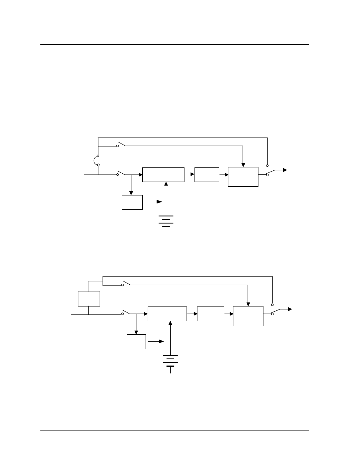
1.3 Schematic Diagram
The UPS supports single-unit operation, and master/slave hot
standby operation as well for the purpose of increasing system
reliability.
Rectifier
Inverter
AC mains
Mains switch
Load
Bypass
Bypass switch
Maintenance bypass
Electronic
transfer
switch
Charger
Hot standby
shorting
stub
Fig. 1-1 Single-unit System
Rectifier
Inverter
AC mains
Mains switch
Load
Bypass
Bypass switch
Maintenance bypass
Maintenance
switch
Electronic
transfer
switch
Charger
Slave
Master UPS
Fig. 1-2 Master/Slave Hot Standby System
2 Chapter 1 Product Introduction
E1-20010916-C-1.0
Page 15

1.4 Features
iTrust series 6kVA/10kVA is an intelligent online UPS system with
sine wave output newly developed by Avansys Power Co., Ltd.
The system adopts high-frequency double conversion topology
structure with high input power factor, wide input voltage range,
and output immune from interference, hence the product is
suitable for areas with unstable mains supply;
It adopts advanced full digital control technology based on DSP
to achieve high system reliability, features self-protection and
fault diagnosis;
It features excellent intelligent battery management, extending
battery life;
The panel operation interface adopts LCD and LED displays,
facilitating user to learn about the system operation state and
operating parameters (for instance: input/output voltage and
frequency, load, battery capacity, internal temperature, etc.);
With Avansys monitoring software, flexible network
management of UPS can be achieved;
The system has maintenance bypass switch, which enables
online maintenance, ensuring no interruption in power to load
during maintenance;
The system design features drawer-type battery installation,
enabling easy and quick maintenance and replacement.
Chapter 1 Product Introduction 3
E1--20010916-C-1.0
Page 16
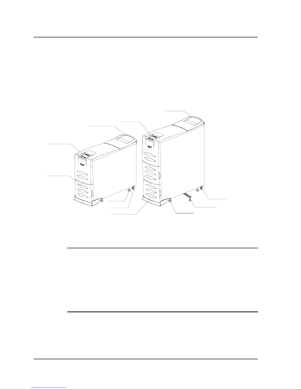
1.5 Appearance and Panels
1.5.1 Appearance
LCD panel
LCD panel
Air inlet
Air inlet
wheel
wheel
Adjustable foot
Adjustable foot
Rear handle
Rear handle
Retractable supporting rack
6kVA UPS 10kVA UPS
Fig. 1-3 System Appearance
Notice:
1. The rear handle is only used to push or pull the UPS, it can not be
used to lift it. Lifting the UPS by the handle will damage the UPS;
2. There are 2 retractable supporting racks at the bottom of the
10kVA UPS chassis, which are used to place the UPS securely
when necessary.
4 Chapter 1 Product Introduction
E1-20010916-C-1.0
Page 17

1.5.2 LCD Panel
The LCD panel consists of LCD, LED and buttons, as shown in Fig.
1-4, for the display and control of operating parameters, alarm
information and function settings.
OFFbutton
Mains indicator
ON/SILENCEbutton
Fault indicator
ENTERbutton
Bypass indicator
CIRCLE
button
Battery indicator
LCD screen
Inverter indicator
Fig. 1-4 LCD Panel Components
I. Composition of LCD panel
This panel includes a group of LED indicators, a LCD screen, and 4
buttons.
1. The LED indicators include 4 green lights and 1 red light.
2. The LCD screen can display maximally 2 lines of information in
Chinese or 4 lines of information in English.
3. The 4 buttons are ON/SILENCE button, OFF button, CIRCLE
button, and ENTER button.
Chapter 1 Product Introduction 5
E1--20010916-C-1.0
Page 18

II. LED display
1) Fault indicator (red): shines in the event of fault, and goes off
otherwise.
2) Mains indicator (green): shines when the mains is normal, goes off
in the event of mains failure, and flashes when the mains voltage is
outside tolerances.
3) Inverter indicator (green): shines when the inverter is supplying
power, and goes off otherwise.
4) Bypass indicator (green): shines when the bypass is supplying
power, and goes off otherwise.
5) Battery indicator (green): shines when the battery is supplying
power, and goes off otherwise,
III. LCD display
1) Operating parameters
Input voltage, input frequency, output voltage, output frequency,
output current, load, internal temperature, battery residual
capacity/in charge state/full charged, battery voltage/charging
voltage.
2) Alarm information (listed by order of priority from high to low)
UPS shutdown, auxiliary supply fault, output short-circuit, inverter
fault, rectifier fault, internal overtemperature, overload, charger fault,
battery fault, UPS shutdown imminent due to low battery, output
fault.
3) Function setup
6 Chapter 1 Product Introduction
E1-20010916-C-1.0
Page 19
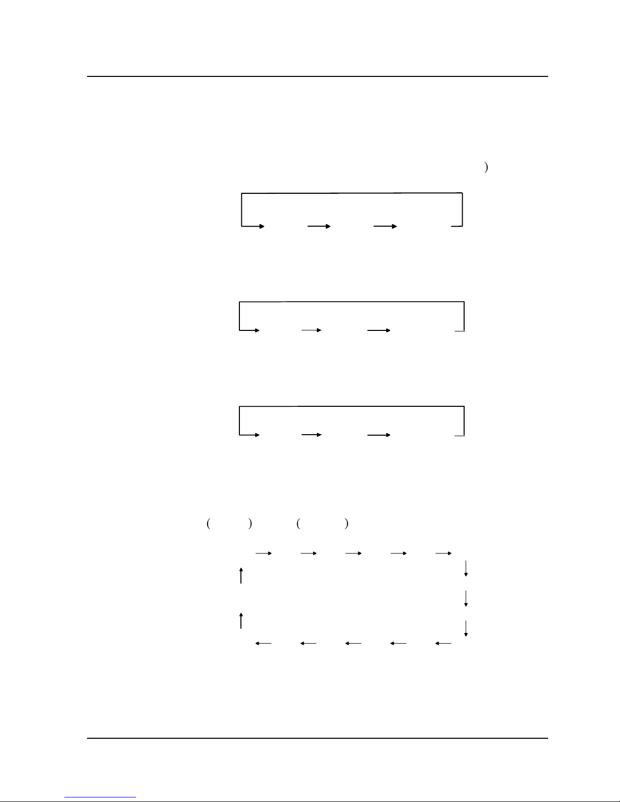
Including setup of Chinese/English menu, equalize charge function,
temperature compensation, battery capacity, master/slave/single-unit,
alternate operation period.
Chinese/English menu setup: (factory default: Chinese
CHINESE
ENGLISH
CANCEL SET
Equalize charge setup: (factory default: enable)
ENABLE DISABLE
CANCEL SET
Temperature compensation setup: (factory default: enable)
ENABLE DISABLE
CANCEL SET
Battery capacity setup: the battery capacity shows the total
battery capacity of the UPS, options include: (factory default:
7Ah
6kVA /14Ah 10kVA )
7Ah
14Ah 24Ah
28Ah 38Ah
42Ah
48Ah
56Ah
65Ah76Ah84Ah
100Ah130Ah
200Ah
CANCEL SET
Master/slave/single-unit setting: (factory default: single)
Chapter 1 Product Introduction 7
E1--20010916-C-1.0
Page 20
MASTER
SLAVE
SINGLE
CANCEL SET
Setup of alternate operation period is allowed only in the master
UPS, specifying the master/slave alternate operation period;
(factory default: 7 days)
7 DAYS
30 DAYS 90 DAYS
180 DAYS
CANCEL
SET
IV. Buttons
For entering into menu, confirming parameter selection
and returning to upper-level menu.
ENTER button
For shifting between menu items of the same level and
selecting parameters, i.e., crosswise circling.
CIRCLE button
When the UPS is supplying power through inverter,
pressing and holding this button for 1 second can stop
the inverter output (i.e., turn off the inverter).
OFF button
When the UPS is supplying power through bypass,
pressing and holding this button for 1 second can start
the inverter output (i.e., turn on the inverter); when the
UPS is supplying power through inverter, which obtains
power from rectifier, pressing and holding this button for
4 seconds can perform manual battery test; when the
UPS is giving audible alarm, pressing this button can
silence the alarm sound.
ON/SILENCE
button
UsageButton
8 Chapter 1 Product Introduction
E1-20010916-C-1.0
Page 21

V. UPS English menu
Internal overtemperatureTEMP OVER
Charger faultCHARGER FAIL
Battery faultBATTERY FAIL
Output short-circuitOUTPUT SHORT
overloadOVERLOAD
UPS shutdown imminent due to low
battery
BATTERY LOW TO BE
SHUTDOWN
Alarm informationWARNING INFO
Return back to the main menuBACK TO MAIN MENU
Internal temperatureUPS TEMP
loadLOAD STATUS
Battery residual capacityBATTERY STATUS
Battery full chargedFULL CHARGED
In charge stateCHARGING
Charging voltageCHARGER VOLT
Battery voltageBATTERY VOLT
Mains frequencyLINE FREQ
Mains voltageLINE VOLT
Output frequencyOUTPUT FREQ
Output currentOUTPUT CURRENT
Output voltageOUTPUT VOLT
Operating parametersOPERATION STATUS
Meaning
English menu
Chapter 1 Product Introduction 9
E1--20010916-C-1.0
Page 22

Chinese CHINESE
English ENGLISH
Single-unit systemSINGLE
Slave UPSSLAVE
Master UPSMASTER
CancelCANCEL
Disable DISABLE
Enable ENABLE
Master/slave alternate operation timeM/S ALTERNATING WORK TIME
Master/slave setupM/S SET
Battery capacity setupBATT CAP SET
Enable or disable temperature
compensation
TEMP COMP SET
Enable or disable equalize chargingEQUALIZATION CHARGE SET
Language selectionLANGUAGE SET
Function setupFUNCTION SETUP
The alarm has been removed, return
back to the main menu
NO WARNING BACK TO MAIN
Under self-testSELF-TESTING
UPS shutdownUPS SHUTDOWN
Auxiliary supply failAUX SUPPLY FAIL
Rectifier faultRECTIFIER FAIL
Inverter faultINVERTER FAIL
Inverter static switch shortcircuitOUTPUT FAIL
Meaning
English menu
10 Chapter 1 Product Introduction
E1-20010916-C-1.0
Page 23

1.5.3 Rear Panel
RS-232 DRY CONTACT
INTELLIGENT SLOT
INPUT BREAKERBYPASS BREAKER
MAINTAIN SWITCH
DRY CONTACTRS-232
INTELLIGENT SLOT
BYPASS BREAKERINPUT BREAKER
MAINTAIN SWITCH
Mains switch
Bypass switch
Air vent
Maintenance switch cover
RS-232 comm port
Dry contact port
SNMP adaptor slot
Terminal block cover
Bypass switch
Input/output terminel block
Mains switch
Maintenance switch
6kVA UPS 10kVA UPS
Fig. 1-4 Rear Panel Components
Usage of rear panel components:
For connecting UPS input/output, and
external battery of long backup time
UPS.
Input/output terminal
block
Used to control the input power of the
UPS bypass.
6kVA UPS adopts 40A/250V AC circuit
breaker;
10kVA UPS adopts 80A/250V AC circuit
breaker.
Bypass switch
Used to control the UPS mains input.
6kVA UPS adopts 63A/250V AC circuit
breaker;
10kVA UPS adopts 80A/250V AC circuit
breaker.
Mains switch
Chapter 1 Product Introduction 11
E1--20010916-C-1.0
Page 24

For UPS heat dissipation.Air outlet
To prevent electric shock resulting from
wiring terminal being exposed.
Terminal block cover
With the optocoupler dry contact port
and monitoring software, the UPS can
be monitored and controlled.
Dry contact port
With the standard RS-232 port and
monitoring software (delivered with the
UPS), the UPS can be monitored and
controlled.
RS-232 port
Used to install SNMP adaptor (optional
component), through which the UPS
can be directly connected into network
to achieve UPS monitoring.
SNMP adaptor slot
To ensure uninterrupted power supply to
load during online maintenance.
Nonprofessional service personnel is
not allowed to use this switch at will.
Maintenance switch
12 Chapter 1 Product Introduction
E1-20010916-C-1.0
Page 25

Chapter 2 Installation
2.1 Unpacking Inspection
1. Open the packing box and take out the UPS, be careful not to
drop it as it is heavy.
2. Check whether the UPS has been damaged in transport. In the
event of any damage to the UPS, please notify the distributor for a
check and don’t turn it on.
3. Check the accessories against the delivery accessory list, please
contact the distributor if any accessory is missing.
2.2 Installation
2.2.1 Matters Needing Attention
1. Please place the UPS on the even ground near load.
2. The distance from the rear and side panels of the UPS to the wall
or other equipment should be greater than 20cm, and the air inlets
on the front panel and at the bottom of the UPS should be kept
unblocked, so as to facilitate ventilation and heat dissipation.
Otherwise, the UPS internal temperature will rise, which will shorten
UPS lifetime.
3. Install the UPS in environment with good ventilation, avoid
installing it in environment with excessive temperature or humidity,
keep the UPS away from water, flammable, explosive substances,
corrosive materials, heat source and direct sunlight, and better keep
the air inlet/outlet free of dust.
Chapter 2 Installation 13
E1-20010916-C-1.0
Page 26

4. Install the UPS in environment free of dust, volatile gas, salt, and
corrosive materials.
5. Don’t install it in open area.
6. Double-pole linkage circuit breaker with capacity greater than 63A
(6kVA UPS) or 80A (10kVA UPS) should be installed on the input
neutral line and live line, so that the input power can be quickly cut
off in case of emergency.
7. To prevent UPS from moving during operation, see to it that the
adjustable feet have been screwed down to place the UPS securely
on the ground prior to use.
8. The UPS is suitable for resistive-capacitive load (like computer),
resistive load and micro-inductive load; it is not suitable for purely
inductive load and purely capacitive load (like motor, air-conditioner
and duplicator); it can not assume half-wave rectifier load.
9. To ensure the safety of the UPS and user equipment, please
adopt correct power distribution:
Input live
line
Input
neutral line
Output
neutral line
U
P
S
Load
N
E
Double-pole
linkage circuit
breaker
L
Output live
line
Fig. 2-1 a Correct Distribution
14 Chapter 2 Installation
E1-20010916-C-1.0
Page 27

Input live
line
Input
neutral line
U
P
S
Load
N/E
L
Output live
line
Output
neutral line
Fig. 2-1
b Wrong Distribution
2.2.2 Installing the UPS
I. Connect external battery of long backup time UPS
This step is saved for standard UPS.
1. Be sure that the cell number is in compliance with the UPS
specifications (twenty 12V cells in series). After connecting the cells
in series, use a voltmeter to confirm that the battery voltage is about
240Vdc;
Notice:
Battery cells by different manufacturer, of different model or use
state can not be combined together.
2. Make sure that the battery switch is placed to OFF;
3. Remove the terminal block cover, use a voltmeter to confirm that
the battery wiring terminals on the UPS input/output terminal block
have no DC voltage;
4. As shown in Fig. 2-2, respectively connect the positive pole (red)
and negative pole (black) of the battery to the battery wiring
Chapter 2 Installation 15
E1-20010916-C-1.0
Page 28

terminals “+” and “-” on the UPS input/output terminal block, and
fasten the fixing screws. Be careful not to reversely connect the
positive and negative poles of the battery. The length of the
connection cables between the battery and the UPS should be as
short as possible.
Battery (+)
Battery (-)
Battery
Battery switch
Fig. 2-2 Connection of External Battery
Notice:
Battery connection and replacement should be carried out when the
UPS in power-off state . When conducting online replacement, be
sure not to reversely connect the battery!
II. Connect UPS input/output cables
As to 6kVA UPS, all the input/output cables (including cables to
connect the hot standby L terminal, B terminal and battery wring
terminals
)
should be at least 10AWG or 6mm2 copper wires; as to
10kVA UPS, all the input/output cables (including cables to connect
the hot standby L terminal, B terminal and battery wring terminals
)
should be at least 8AWG or 10mm2 copper wires.
16 Chapter 2 Installation
E1-20010916-C-1.0
Page 29

1. Before connection, please confirm that all input and output circuit
breakers are placed to OFF;
2. As shown in Fig. 2-3, remove the terminal block cover, connect
the input cables (live line, neutral line and ground line) respectively
to the corresponding input terminals, and fasten the fixing screws;
Battery cable(-)(long backup time UPS)
Output live line
Output neutral line
Hot standby L terminal
Hot standby B terminal
Input live line
Input neutral line
Input ground line
L
N
B
L
+
_
N
L
Output ground line
Battery cable(+) (long backup time UPS)
Fig. 2-3 Wiring Diagram of Input/output Terminal Block
Notice:
1. To ensure reliable connection, all connection cables must use
cable lug.
2. Never reversely connect the neutral line and the live line!
3. Wall socket power can not be used as UPS input power.
Otherwise, the socket may be burned.
3. Connect the UPS output cables (live line, neutral line and ground
line) and the load power lines (live line, neutral line and ground line)
correctly to a power distribution cabinet, fasten the fixing screws,
and mount the terminal block cover of the UPS.
Note: When connecting the output cables, be sure that the neutral
line, live line and ground line are correctly and reliably connected.
For the sake of safety, the ground line must be connected before the
neutral line and live line.
Chapter 2 Installation 17
E1-20010916-C-1.0
Page 30

III. Connect UPS communication cable
1. User may, according to actual needs, use the RS-232 cable
(universal type) delivered with the UPS to connect the RS-232 port of
the UPS to that of the computer, or use the dry contact cable to
connect the dry contact port of the UPS to the RS-232 port of the
computer (connect the cable end marked with “UPS” to the dry
contact port, and the end marked with “PC” to the computer), as shown in
Fig. 2-4. The 2 connection methods result in different
communication functions, as described in Appendix 1. User may
refer to Appendix 1 to select suitable connection method.
RS-232
DRY CONTACT
INTELLIGENT SLOT
INPUT BREAKERBYPASS BREAKER
MAINTAIN SWITCH
RS232 cable
computer
Fig. 2-4 Connection Between UPS Communication Port and Computer
(Take RS-232 cable as an example)
2. For users who use SNMP adaptor, please follow the steps below
to install the SNMP adaptor:
Remove the screws of the SNMP adaptor slot cover, then take off
the cover, as shown in Fig. 2-5(a). Retain the cover for future use;
Insert the SNMP adaptor into the slot, and fix it with screws, as
shown in Fig. 2-5(b);
18 Chapter 2 Installation
E1-20010916-C-1.0
Page 31

Use network connection cable to connect the UPS to the network
port of the computer, as shown in Fig. 2-5(c);
For setting of the SNMP adaptor, please refer to the documents
delivered with the monitoring software.
Fig. 2-5 a Fig. 2-5 b
BYPASS BREAKERINPUT BREAKER
Concentrater
Network connection cable
MAINTAIN SWITCH
DRY CONTACT
RS-232
INTELLIGENT SLOT
Fig. 2-5 c
Fig. 2-5 Installation of SNMP Adaptor
Chapter 2 Installation 19
E1-20010916-C-1.0
Page 32

2.3 Wiring of Master/Slave Hot Standby System
1. Be sure that the input circuit breakers of the master UPS and
slave UPS are all in the OFF position, and neither UPS has output;
2. Remove the shorting stub between the hot standby L terminal and
B terminal of the master UPS. Retain it, as it may be used in the
future;
3. Perform wiring as shown in Fig. 2-6.
Note: Make sure that the neutral lines, live lines and ground lines
are correctly and reliably connected. In the case of master/slave hot
standby system adopting long backup time UPS, the master UPS
and the slave UPS should have separate external battery, i.e. They
can not share the same external battery.
Slave output live line connected to Master bypass
I
n
p
u
t
g
r
o
u
n
d
l
i
n
e
N
L
L
B
+
_
L
N
Slave
Output ground lines in parallel
Master
N
L
L
B+
_
L
N
Input live lives in parallel
Input neutral lines in parallel
Input ground lines in parallel
Slave neutral line connected to battery input terminel(-)
I
n
p
u
t
n
e
u
t
r
a
l
l
i
n
e
I
n
p
u
t
l
i
v
e
l
i
n
e
M
a
s
t
e
r
i
n
p
u
t
l
i
v
e
l
i
n
e
M
a
s
t
e
r
i
n
p
u
t
n
e
u
t
r
a
l
l
i
n
e
M
a
s
t
e
r
i
n
p
u
t
g
r
o
u
n
d
l
i
n
e
Fig. 2-6 Wiring Diagram of 6kVA/10kVA Master/Slave Hot Standby System
20 Chapter 2 Installation
E1-20010916-C-1.0
Page 33

Wiring requirements of master/slave hot standby system:
The input/output cables of 6kVA UPS should be at least 10AWG or
6mm
2
copper wires;
The input/output cables of 10kVA UPS should be at least 8AWG or
10mm
2
copper wires.
Chapter 2 Installation 21
E1-20010916-C-1.0
Page 34

Page 35

Chapter 3 Operation
3.1 Operation Mode
The UPS has 4 operation modes: Normal mode, Bypass mode,
Battery mode, and Fault mode.
3.1.1 Normal Mode
When the input mains voltage and the load are within specifications,
the load is supplied by inverter, which obtains power from rectifier;
meanwhile, the charger float-charges or equalize-charges the
battery. When in Normal mode, the mains indicator and inverter
indicator on the LCD panel shine green, as shown in Fig. 3-1.
220.0V
OUTPUT VOLT
Fig. 3-1
Chapter 3 Operation 23
E1-20010916-C-1.0
Page 36

Notice:
If the UPS is supplied by AC generator, please follow the requirements below
:
1
. Start up the AC generator first without switching on the loads, connect the
UPS to the generator, then switch on the loads one by one till the generator
operates stably (to ensure reliable operation of the generator, it is
recommended that the UPS load be less than 30% of generator capacity).
2. It is recommended that the generator capacity be 1.5~2 times of UPS rated
capacity.
3.1.2 Bypass Mode
When the UPS is supplied with AC mains without being turned on,
or in the event of overload or other faults after the UPS is turned on,
the load is supplied by Bypass AC source, which comes directly
from the AC mains input; and meanwhile the charger charges the
battery. When in Bypass mode, the bypass indicator on the LCD
panel shines green, as shown in Fig. 3-2. Please note: In the event
of bypass power failure or bypass voltage outside tolerances when
the UPS is in Bypass mode, the UPS is unable to supply the load.
215.0V
OUTPUT VOLT
Fig. 3-2
3.1.3 Battery Mode
When the UPS is in Normal mode, in the event of mains failure or
mains voltage outside tolerances, the rectifier and charger stop
24 Chapter 3 Operation
E1-20010916-C-1.0
Page 37

running, the battery begins to discharge and supply the load through
inverter. When the UPS operates in Battery mode, the battery
indicator and inverter indicator on the LCD panel shine green, as
shown in Fig. 3-3, accompanied with a beep every 3 seconds, giving
alarm that the UPS is operating in Battery mode.
220.0V
OUTPUT VOLT
Fig. 3-3
In Battery mode, when the battery voltage is low, there is a beep
every 1 second, and the LCD screen reads “BATTERY LOW TO BE
SHUTDOWN”, giving alarm for timely processing.
Note: Although the battery had been fully charged at factory before
despatch, the transport and storage resulted in loss of electricity
quantity, hence charging the battery for 8 hours is required before
using the UPS for the first time, so as to ensure adequate battery
backup time.
3.1.4 Fault Mode
In the event of inverter fault, internal overtemperature or other faults
in Normal mode, the UPS transfers to Bypass mode; in the same
cases in Battery mode, the UPS shuts down.
In the event of UPS fault, the fault indicator on the LCD panel shines
red, as shown in Fig. 3-4. Meanwhile, the buzzer beeps (except
Chapter 3 Operation 25
E1-20010916-C-1.0
Page 38

battery and charger fault), and the LCD screen displays
corresponding fault information.
215.0V
OUTPUT VOLT
Fig. 3-4
3.2 Operation
3.2.1 System Power-on
After checking and making sure that the input and output cables are
connected correctly, turn on the mains switch and the bypass switch
(for long backup time UPS, turn on the battery switch before closing
the mains switch). Then the system starts up, the internal fan begins
to run, and the system begins to conduct self-test. After system
self-test (the buzzer beeping twice means normal startup), the
system enters in Bypass mode, the mains indicator and bypass
indicator shine green, as shown in Fig. 3-5:
26 Chapter 3 Operation
E1-20010916-C-1.0
Page 39

215.0V
OUTPUT VOLT
Fig. 3-5
3.2.2 System Parameter Setting
After system power-on, press the CIRCLE button to view the LCD
display. When the LCD screen displays “BACK TO MAIN MENU”,
press the ENTER button to return to the main menu. Again press the
CIRCLE button, when the LCD screen displays “FUNCTION
SETUP”, as shown in Fig. 3-6, press and hold the ENTER button for
more than 5 seconds to enter the function setup state. User may set
according to the actual UPS configuration the equalize charge
function, temperature compensation function, battery capacity (the
aforesaid setup is needed only for long backup time UPS, that of
standard UPS had been completed at factory), master/slave/single
and alternate operation time (this step is saved for single-unit
system). See Section 1.5.2 for detailed information.
Chapter 3 Operation 27
E1-20010916-C-1.0
Page 40

FUNCTION
SETUP
3
Fig. 3-6
After setting system parameter, please save the settings following
the steps below:
1. Make sure the UPS is in Bypass mode, disconnect the mains
input and bypass switches (don’t switch off the battery air breaker of
the long backup time UPS, if any);
2. Wait for about 30 seconds until the internal fan stops and the LCD
screen has no display (only after that can the set parameters be
saved in the system);
3. Turn on the mains input and bypass switches to start up the
system, up to now, the settings have been saved in the system.
3.2.3 Start Inverter Output
I. Start Normal mode
1. After system power-on, press and hold the ON/SILENCE button
for 1 second, then a beep is heard. Several seconds later, the
bypass indicator goes off and the inverter indicator shines, as shown
in Fig. 3-7, which means the UPS is operating in Normal mode.
28 Chapter 3 Operation
E1-20010916-C-1.0
Page 41

220.0V
OUTPUT VOLT
Fig. 3-7
Note: If the previous shutdown is automatic resulting from
termination of battery discharge because of AC mains failure, the
automatic turn-on function (this function is settable through
background monitoring software and had been set at factory ) will be
activated when the AC mains restores.
2. When the system begins to operate stably, gradually add loads to
the system. The load information can be queried through the LCD
screen, as shown in Fig. 3-8:
70.0%
LOAD STATUS
Fig. 3-8
3. If the buzzer beeps every 0.5 second and the LCD displays
“OVERLOAD”, it indicates that overload exists. In this case, some
less critical loads should be disconnected. Usually it is
Chapter 3 Operation 29
E1-20010916-C-1.0
Page 42

recommended the UPS assume no more than 70% rated load so
that the system operation won’t be affected by abrupt load
fluctuation and the UPS lifetime can be extended.
Notice
If the system transfers from Normal mode to Bypass mode for 3
times within 1 hour due to overload, it will remain in Bypass mode
for 1 hour and can’t transfer back to Normal mode till the overload is
removed.
II. Start Battery mode
In the event of mains failure, user may turn on the UPS to start
Battery mode to supply the load.
1. Press and hold the ON/SILENCE button for about 1 second, after
a beep and system self-test, the battery indicator and inverter
indicator shine green, as shown in Fig. 3-9, and the buzzer beeps
every 3 seconds, indicating the UPS is operating in Battery mode.
220.0V
OUTPUT VOLT
Fig. 3-9
2. The loading process is the same as described in Section “Start
Normal mode”.
30 Chapter 3 Operation
E1-20010916-C-1.0
Page 43

Notice
In the event of overload during the loading process after starting
Battery mode, immediately disconnect some loads till the overload
alarm stops, otherwise, the system will stop output after a delay
time.
3.2.4 Manual Battery Test
When in Normal mode, provided that the mains voltage is normal,
no overload exists, and the battery voltage is no lower than 240V,
battery test can be conducted by pressing button on the LCD panel
(for battery test through background monitoring software, see the
documents delivered with the software): press and hold the
ON/SILENCE button for 4 seconds (a beep is heard 3 times) and
then relieve it. 3 seconds later, the battery test begins, the battery
indicator shines, and the buzzer beeps as in Battery mode. After
battery test, the buzzer stops beeping, the battery indicator goes off,
and the displays of the panel indicators restore to the state prior to
test. When battery fault is detected (no battery, faulty battery, or
battery reverse connection) during test, the fault indicator shines,
and the LCD screen displays “BATTERY FAIL”, as shown in Fig.
3-10.
BATTERY FAIL
Fig. 3-10
Chapter 3 Operation 31
E1-20010916-C-1.0
Page 44

Notice
After battery test, the battery state information will be refreshed. In
the event battery fault that the battery is not fully charged is detected
during test, user may re-test the battery after fully charging it to
confirm that the fault is removed.
3.2.5 Turn off Inverter
1. When the system has AC mains input and the AC mains is
normal, press and hold the OFF button for about 1 second, then a
beep is heard, the inverter indicator goes off and the bypass
indicator shines, as shown in Fig. 3-11, indicating the UPS has
transferred to Bypass mode.
215.0V
OUTPUT VOLT
Fig. 3-11
2. When the system has no AC mains input (in Battery mode), press
and hold the OFF button for about 1 second, then a beep is heard,
the UPS stops output and the LCD screen displays “UPS
SHUTDOWN”. About 30 seconds later, all panel indicators go off,
and the fan stops running.
32 Chapter 3 Operation
E1-20010916-C-1.0
Page 45

3.2.6 System Power-off
After turning off the inverter, place the mains switch and the bypass
switch to OFF, all panel indicators go off, and the fan stops running
(if there is a battery, a delay time of 30 seconds is needed before
the fan stops). Up to now, the system is powered off. If the UPS is
connected to external battery, place the switch of the external
battery to OFF. After system power-off, the UPS has no output to
supply the load.
3.3 Auto Transfer Between UPS Operation Modes
In normal case, user should set the UPS to Normal mode. When
operating in Normal mode, in the event of mains failure, the UPS
automatically transfers to Battery mode without interruption to load;
in the event of overload, the UPS automatically transfers to Bypass
mode without interruption to load; in the event of inverter fault or
internal overtemperature, the UPS operates in Fault mode.
3.3.1 Transfer to Bypass Mode in the Event of Overload
When the UPS remains overloaded for a specified time, the UPS
transfers from Normal mode to Bypass mode, and meanwhile gives
audible alarm every 0.5 second. In such case, the UPS output is
mains voltage. At this time, some loads should be disconnected until
the alarm stops, and 5 minutes after that, the UPS automatically
transfers back to Normal mode. To protect the load and UPS, the
transfer times within 1 hour from Normal mode to Bypass mode due
to overload should be less than 3, otherwise, the UPS will remain in
Bypass mode for 1 hour before it transfers back to Normal mode.
Chapter 3 Operation 33
E1-20010916-C-1.0
Page 46

3.3.2 Transfer to Battery Mode in the Event of Mains Failure
In the event of mains failure, the UPS transfers to Battery mode.
when the battery is completely discharged, the UPS automatically
shuts down. When the mains restores, the UPS automatically turns
on and operates in Normal mode. This function is designed for
unattendance. If the UPS is manually shut down in Battery mode, it
can only be turned on to inverter manually when the mains restores.
3.3.3 Transfer to Bypass Mode in the Event of Overtemperature
High ambient temperature and poor ventilation may result in
overtemperature inside UPS. In the event of internal
overtemperature, the UPS transfers to Bypass mode, the fault
indicator shines red, the LCD screen displays “TEMP OVER”, and
the UPS gives audible alarm. In such case, cut off the input AC
mains (by switching off the input air breaker), remove any
substances blocking ventilation, or widen the distance from wall.
After the UPS cools down, supply it with AC mains and turn it on.
3.3.4 Output Short-circuit Protection
In the event of load short-circuit, the UPS stops output, the fault
indicator shines red, the LCD screen displays “OUTPUT SHORT”,
and the UPS gives audible alarm. In such case, disconnect the
concerned load, and cut off the input power of the UPS. 10 minutes
later, the UPS automatically shuts down (or manually shut down the
UPS 10 seconds later by pressing the OFF button). After removing
the short-circuit fault, connect the load back to the UPS, supply the
UPS with AC mains and turn it on.
34 Chapter 3 Operation
E1-20010916-C-1.0
Page 47

3.4 UPS Monitoring
For the information on background monitoring of UPS, please see
the documents delivered with the monitoring software.
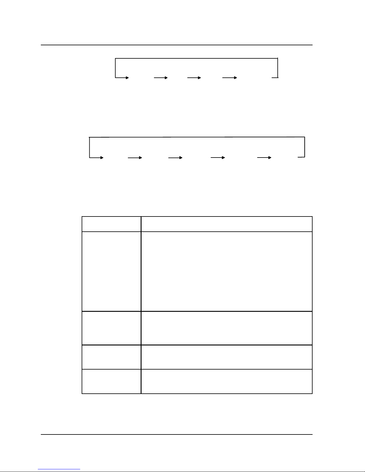
3.5 LCD Menu Operation
The button operation process is shown in Fig. 3-11:
Chapter 3 Operation 35
E1-20010916-C-1.0
Page 48

WARNING INFO
... ...
...
FUNCTION SETUP
Press and hold
for 5 seconds
OUTPUT FREQ
BACK TO MAIN MENU
CIRCLE
( )
( )
ENTER
OPERATION STATUS
OPERATION STATUS
OPERATION STATUS
OUTPUT VOLT
BACK TO MAIN MENU
ENTER
ENTER
ENTER
ENTER
ENTER
ENTER
ENTER
ENTER
OPERATION STATUS
BACK TO MAIN MENU
EQUALIZATION
CHARGE SET
Current value
Current value
ENTER
The 1st current alarm
The 2st current alarm
ENABLE
TEMP COMP SET
CANCEL SET
DISABLE
CIRCLE
CIRCLE
CIRCLE
CIRCLE
CIRCLE
CIRCLE
CIRCLE
CIRCLE
CIRCLE
CIRCLE
CIRCLE
CIRCLE
CIRCLE
CIRCLE
CIRCLE
CIRCLE
CIRCLE
Fig. 3-11 Button Operation Block Diagram
36 Chapter 3 Operation
E1-20010916-C-1.0
Page 49

1. Shift between level 1 menus
Press the CIRCLE button to shift between the WARNING INFO,
OPERATION STATUS and FUNCTION SETUP menus. Press the
ENTER button to enter the WARNING INFO, OPERATION STATUS
or FUNCTION SETUP menus.
Note: It is required to press and hold the ENTER button for more
than 5 seconds to enter into the FUNCTION SETUP menu.
2. Shift between level 2 menus
A. After entering into the OPERATION STATUS menu, pressing the
CIRCLE button can circularly view the running data; when the
screen displays “BACK TO MAIN MENU”, press the ENTER button
to return to the main menu.
B. After entering into the FUNCTION SETUP menu, pressing the
CIRCLE button can circularly view the settable function information;
when the screen displays “BACK TO MAIN MENU”, press the
ENTER button to return to the main menu OPERATION STATUS.
C. After entering into level 2 menu under FUNCTION SETUP menu,
the parameter value is displayed in highlight; at this time, pressing
the CIRCLE button can circularly modify the value; press the
ENTER button to save the modifications; after that, the parameter
value is not displayed in highlight.
D. In the event of alarm, pressing the CIRCLE button can circularly
view historical alarm; when the screen displays “BACK TO MAIN
MENU”, press the ENTER button to return to the main menu
OPERATION STATUS.
Chapter 3 Operation 37
E1-20010916-C-1.0
Page 50

3. Priority of LCD display information
A. When the system is in alarm state, the LCD screen will
automatically display the alarm information of the highest priority if
there is no effective button operation within 30 seconds.
B. When there is no alarm, and the LCD screen is displaying level 2
menu under OPERATION STATUS menu, say, OUTPUT
CURRENT, the LCD display information will remain unchanged if
there is no effective button operation; however, when there is no
alarm, and the LCD screen is not displaying level 2 menu under
OPERATION STATUS menu, the LCD will automatically display
“OUTPUT VOLT: xxx” if there is no effective button operation within
30 seconds.
38 Chapter 3 Operation
E1-20010916-C-1.0
Page 51

Chapter 4 Maintenance
Using Avansys iTrust series UPS in specified ambient environment
(see Section 2.2.1) can reduce maintenance.
I. Fan
The fan is expected to be able to run for 20000~40000 hours
continuously. The higher the ambient temperature, the shorter the
fan life. During system operation, please regularly check whether all
fans are operating normally and there is air blowing out from inside.
II. Battery Maintenance
The internal battery of iTrust series UPS is sealed, lead-acid,
maintenance-free battery. The battery life depends on the ambient
temperature, charge and discharge times. High ambient
temperature and deep discharge will shorten battery life.
To ensure battery life, the battery should be maintained regularly:
Keep the ambient temperature between 15
and 25 .
To prevent small current discharge, continuous battery
discharge time exceeding 24 hours is strictly prohibited.
When the UPS hasn’t been used for a long time, and the battery
hasn’t been charged for 3 months at specified ambient
temperature, or 2 months at high ambient temperature, please
charge it for at least 12 hours.
Chapter 4 Maintenance 39
E1-20010916-C-1.0
Page 52

As to external battery of long backup time UPS, the wiring
terminals of the external battery must be checked regularly and,
when necessary, should be cleaned.
If the battery backup time is found greatly shortened, or when the
UPS LCD displays “BATTERY FAIL”, please contact the distributor
to confirm whether the battery needs to be replaced. Before
replacement, please make sure that the specifications of the new
battery are correct.
Notice
1. Never short-circuit the battery terminals, which will result in fire.
2. Never open the battery, as the electrolyte is harmful to human
body. In the event of inadvertent contact of electrolyte, immediately
rinse it off and go to hospital for a check.
III. Keep Air Vent Unblocked
1. Regularly clean the system, especially the air inlet and air outlet.
Make sure the air flows freely inside the chassis. Use dust collector
for cleaning when necessary.
2. Check the air vents on the front, rear, and side panels, make sure
they are not blocked.
IV. UPS State Check
1. Check whether the UPS is faulty: is the fault indicator shining? Is
fault alarm being given?
2. Is the UPS operating in Bypass mode: in normal case, the UPS
operates in Normal mode; if it is operating in Bypass mode, please
40 Chapter 4 Maintenance
E1-20010916-C-1.0
Page 53

find out the reason, for instance: operator intervention, overload,
internal fault, etc.
3. Is the battery discharging: when the AC mains is normal, the
battery shouldn’t discharge; if the UPS is operating in Battery mode,
please find out the reason, for instance: mains failure, battery test,
operator intervention, etc.
V. Function Inspection
It is recommended to inspect the UPS functions once half year.
1. Press the OFF button, check whether the buzzer, LED indications
and LCD display are normal (see Section 3.1 Operation Mode).
Please do this after confirming that the AC mains is normal and data
backup has been done.
2. Press the ON/SILENCE button, check again whether the LED
indications and LCD display are normal and the UPS transfers to
Normal mode.
3. When the inverter is in Normal mode (the inverter indicator
shines), press and hold the ON/SILENCE button for 4 seconds to
start battery test. Should any battery problem be found, immediately
find out the problem and solve it.
Chapter 4 Maintenance 41
E1-20010916-C-1.0
Page 54

Page 55

Chapter 5 Troubleshooting
In the event of UPS fault, please check it and remove the fault in the
first instance following the methods described in the table below. If
the fault still exists, please contact the distributor, we’ll help you out
of trouble in the shortest time.
If the UPS is operating in
Battery mode, please
note the battery backup
time.
The mains voltage is
outside tolerances.
The mains indicator
flashes.
5
A. Pressing and holding
the ON button for more
than 1 second;
B. Turn on the UPS
again after
disconnecting all loads.
A. The button holding
time is too short;
B. overload.
After pressing the
ON button, the UPS
does not start up.
4
Make sure that the
output power line is
properly connected.
The output power line is
not properly connected.
No alarm is given,
but there is no
voltage output.
3
A. Turn on the input
switch;
B. Make sure that the
input power line is
properly connected;
A. The input switch is
turned off;
B. The input power line
is not properly
connected;
The AC mains is
normal, but the
mains indicator does
not shine and the
UPS operates in
Battery mode.
2
Use voltmeter to check
whether the input mains
voltage is within
tolerances.
A. AC mains hasn’t been
introduced into the
system;
B. Input undervoltage.
No panel display and
system self-test
when the mains
switch is in the ON
position.
1
ActionPossible CauseAlarm or Condition
Serial
No.
Chapter 5 Troubleshooting 43
E1-20010916-C-1.0
Page 56

A. Allow the battery to
charge for more than 8
hours when the AC
mains is normal, and
then re-test the
discharge time;
B. The battery needs
replacement, please
contact the distributor.
A. The battery is not fully
charged;
B. The battery is not able
to hold a full charge due
to age.
The UPS has
reduced battery time.
9
Contact the distributor
for charger
replacement/maintenanc
e.
Charger fault
The fault indicator
shines, and the LCD
displays “CHARGER
FAIL”.
8
A. Check whether the
external battery switch is
turned on and its lead is
properly connected;
B. Check whether the
battery is reversely
connected;
C. Contact the distributor
for battery replacement;
A. The external battery
switch is turned off, or its
lead is not properly
connected;
B. Battery reverse
connection;
C. Battery damaged;
The fault indicator
shines and the LCD
displays “BATTERY
FAIL”.
7
Disconnect some loads
from the UPS.
Overload.
The buzzer beeps
every 0.5 second,
and the LCD
displays
“OVERLOAD”
6
ActionPossible CauseAlarm or Condition
Serial
No.
44 Chapter 5 Troubleshooting
E1-20010916-C-1.0
Page 57

Turn off the UPS and cut
off the power input
immediately, contact the
distributor for help.
UPS internal fault
Abnormal noise or
smell inside the
UPS.
13
The UPS needs
maintenance, please
contact the distributor.
UPS internal fault
The buzzer beeps,
the fault indicator
shines, and the LCD
displays
“RECTIFIER FAIL”,
“INVERTER FAIL”,
“AUX SUPPLY
FAIL”, or “OUTPUT
FAIL”.
12
Restart the UPS after
confirming that load
short-circuit does not
exist.
UPS output short-circuit.
The buzzer beeps,
the fault indicator
shines, and the LCD
displays “OUTPUT
SHORT”
11
A. Check whether there
is air blowing out from
inside.
B. Remove the
substances blocking the
vent, or widen the
distance from the wall;
C. Wait for 10 minutes
until the UPS cools
down, then restart it.
Internal overtemperature
The buzzer beeps,
the fault indicator
shines, and the LCD
displays “TEMP
OVER”
10
ActionPossible CauseAlarm or Condition
Serial
No.
When reporting UPS fault to our company or the distributor, please
inform the machine model and machine No. (the bar code on the
rear panel of the UPS).
Chapter 5 Troubleshooting 45
E1-20010916-C-1.0
Page 58

Page 59

Chapter 6 Service and Support
Avansys Power Co., Ltd. provides customer with satisfactory
technical support. To obtain support, please contact the distributor in
the first instance. When failing to reach the distributor, please
contact your local technical support center or the company
headquarters:
1. User can obtain service through dialing our free toll telephone.
Free toll
800-8302118
2. Web site technical service
User can seek technical support by visiting our technical support
web site.
Technical support web site of Avansys Power Co., Ltd.:
http://www.avansys.com
To facilitate user, we also have special UPS service mailboxes:
hwdy@huawei.com
upsserver@huawei.com
3. We provide 3 years of free service for our 6kVA UPS (including
the internal battery), and 1 year of free service for our 10kVA UPS
(including the internal battery), provided that they are used properly.
The above warranty shall not apply in the following circumstances:
The battery is provided by user;
Damage resulting from operation not in accordance with the
user manual;
Damage as a result of fire, flood, etc.;
Damage caused by transport, move or neglect after purchase;
Chapter 6 After-sales Service 47
E1-20010916-C-1.0
Page 60

Damage caused by power supply not in accordance with
relevant electrical regulations or operation in ambient
environment not in compliance with requirements;
For detailed information on warranty, please see the warranty items.
4. Different levels of customized service packages are available with
reasonable charge, including responsive, preventive maintenance,
warranty period extension, etc. For detailed information, please
contact the distributor or the local technical support center.
48 Chapter 6 After-sales Service
E1-20010916-C-1.0
Page 61

Appendix 1 Communication Port
RS-232 Communication Mode
Port description male)
NC
RXD
TXD
NC
NC
NC
NC
NC
1
2
3
4
5
6
7
8
9
GND
Pin 2: receiving terminal;
Pin 3: transmitting terminal;
Pin 5: common;
Other pins: unconnected.
Connection relationship between RS-232 port of computer and
RS-232 port of UPS
Computer --------------------- UPS
RDX
pin 2
<------------------- TX
pin 3
TDX
pin 3
--------------------> RX
pin 2
GND
pin 5
--------------------- GND
pin 5
RS-232 communication mode provides the following functions:
Monitor the current power supply state of UPS;
Monitor the current alarm information of UPS;
Monitor the current running parameters of UPS;
Time the ON/OFF control of the UPS, and set system
parameters.
Appendix 1 Communication Port 49
E1-20010916-C-1.0
Page 62

RS-232 communication data format
Baud rate ---------- 4800bps
Byte length ---------- 8bit
Stop bit ---------- 1bit
Parity check ---------- none
Dry Contact Communication Mode
Port description
NC
NC
GND
BATTERY LOW
OFF
GND
NC
NC
1
2
3
4
5
6
7
8
9
MAIN FAILURE
Pin 2: this pin turns from OPEN to CLOSE in the event of mains failure, its
normal state is OPEN;
Pin 5: this pin turns from OPEN to CLOSE in the event of battery low voltage,
its normal state is OPEN;
Pin 6: when applying +5V voltage for more than 1 second, the UPS is turned off;
Pin 4: signal ground;
Pin 7: signal ground;
Other pins: unconnected.
Dry contact communication mode provides the following functions:
Provide mains fault information in the event of mains failure;
Provide battery low voltage information when the battery
discharge is about to terminate;
Provide OFF control of UPS
50 Appendix 1 Communication Port
E1-20010916-C-1.0
Page 63

Appendix 2 Grounding & Lightning Protection
The grounding and lightning protection of low voltage power supply
system is a systematic engineering, of which the grounding and
lightning protection of UPS is only a part. According to relevant
international, domestic and industry standards, lightning protection
measures should be taken at the primary and secondary sides of the AC
power transformer before the power line is introduced into the UPS
machine room, and there are stringent requirements on the length and
grounding mode of the low voltage power cable introduced into the UPS
machine room, on the lightning protection, shielding, and lightning
protection ground cable of the UPS machine room.
To ensure human safety, the UPS must be reliably grounded prior to
use, i.e., the UPS protective ground (the metal case of the UPS)
must be reliably connected to the ground bar in the machine room
by connecting the input ground line terminal on the UPS terminal
block to the machine room ground bar. In addition, the mains
frequency ground resistance of the machine room ground bar
should be in compliance with relevant standards, normally less than
5 ohms. To ensure that the ground cable inside the UPS is reliably
and safely connected, the iTrust UPS had undergone stringent
internal ground resistance test at factory before despatch.
The iTrust UPS provides perfect lightning protection. All lightning
protection elements are made by world known manufacturer or
military standard products, and the SPD (surge protection device) is
designed and installed in strict accordance with the IEC standard.
After other lightning protection actions of low voltage power supply
system stated above are taken in compliance with requirements, the
harm that the lightning strike may do to the UPS machine room is
minimized.
Appendix 2 Grounding & Lightning Protection 51
E1-20010916-C-1.0
Page 64

Classified by the different throughput capacity and installation place,
usually the UPS system has no more than 2 levels of lightning
protection. The first level lightning protection adopts C-class SPD (
or
-class) with a max throughput capacity of 40kA, waveform 8/20 s,
installed between the UPS and the AC distributor; the second level
lightning protection adopts D-class SPD
(or -class
) with a max
throughput capacity of 8kA, waveform 8/20
s, installed inside the
UPS. Standard D-class SPD is installed inside the iTrust UPS, and
the SPD24SZ C-class SPD produced by Avansys is recommended.
User may decide whether to select C-class SPD according to the
actual situation of the machine room. Whichever brand C-class SPD
is selected, the connection method shown in the following figure
must be adopted between the C-class SPD and the UPS, i.e., the
protective ground (the UPS metal case) and the C-class lightning
protection ground of the UPS share the same ground, and are then
connected to the ground bar in the machine room.
52 Appendix 2 Grounding & Lightning Protection
E1-20010916-C-1.0
Page 65

wiring
diagram
User
UPS
Protective
ground
Ground
bar
1. Fixation hole 2. Air breaker 3. Integrated lightning protection element
4. Ground copper bar
C-class lightning protection ground
Connection of SPD24SZ SPD
Notes:
1. It is recommended to use copper core cable with sectional area
between 6
25mm² as the live line (L) and neutral line (N) of the
SPD24SZ SPD, and copper core cable with sectional area 10mm²
(minimally 6mm²) as the protective ground cable (PE line). For
detailed installation, please refer to relevant specifications by
Avansys.
2. According to test result, the length of the connection cable
between the C-class SPD box and the UPS is required to be within
5
10m, and it must be ensured that this cable will not suffer
lightning strike. Too short cable length will affect the lightning
protection effect.
3. In applications with high lightning strike hazard, it is
recommended to install B-class (or
-class SPD at 12m or even
Appendix 2 Grounding & Lightning Protection 53
E1-20010916-C-1.0
Page 66

further before the C-class SPD. User may buy and install the
B-class SPD by itself under the technical guidance of Avansys.
54 Appendix 2 Grounding & Lightning Protection
E1-20010916-C-1.0
Page 67

Appendix 3 Technical Specifications
89%88%Efficiency
120 ~253Vac Bypass voltage
105~125% rated load, 5min; 125~150% rated load, 10sOverload capacity
≤
60mS
Transient
recovery time
5% at 100% load step change resistive load
Dynamic
response
≤
4% linear load
≤
5% nonlinear load
Voltage harmonic
distortion
3:1Crest factor
0.7Power factor
≤
1Hz/S
Frequency
synchronization
speed
In Normal mode: synchronizes the bypass frequency
when the bypass frequency is within 50Hz 10%; is
50Hz
0.2% when the bypass frequency is outside
tolerances.
In Battery mode: is 50Hz 0.2%
Frequency
220Vac±2%Voltage
10kVA/7kW6kVA/4.2kWPower rating
Output
≥
0.99Power factor
50Hz±5HzFrequency
176-276Vac, full load;
120-176Vac, linear derating
in loading;
120Vac, half load.
160-276Vac, full load;
120-160Vac, linear
derating in loading;
120Vac, half load.
Voltage range
220VacRated voltage
Input
UH11-0100LUH11-0060L
UH11-0100UH11-0060
Model
Appendix 3 Technical Specifications 55
E1-20010916-C-1.0
Page 68

IP21
Protection class
IEC60664-1-IV, 6kV/3kA hybrid wave for
1.2/50µS+8/20µS
Surge protection
Conduction, emission EN50091-2 EN55022 Class A
Immunity EN61000-4-2.3.4.6.8.11 Level III
EN61000-4-5 Level IV
EMC
CCEE GB4943-1995Safety
LCDDisplay
≤
48dB
≤
45dB
Audible noise (1m)
0
Inverter
↔
Bypass
0
Normal
↔
Battery
Transfer
time
4A, expandable in parallel to 8A (external charger is
needed when battery capacity ≥200Ah)
Charge current
long backup
time UPS
8 hours to 90% rated capacity
Recharge time
standard
UPS
8
min
6min
Backup time at
full load
standard
UPS
240Vdc240VdcRated voltage
4020
Internal cell
number
Sealed, lead-acid, maintenance-free battery 12V/7Ah
Type
Battery
UH11-0100LUH11-0060L
UH11-0100UH11-0060
Model
56 Appendix 3 Technical Specifications
E1-20010916-C-1.0
Page 69

8553
Long backup
time UPS (kg)
190100
Standard UPS
(kg)
Weight
280 875 770280 635 670
W H D (mm)Size
<1500m, derating in accordance with GB/T3859.2 when
it is higher than 1500m
Elevation
5% 95%, non-condensing
Relative
humidity
–40°C +70°C( without battery ) –20°C +55°C ( with
battery)
Storage
temperature
0°C +40°C
Operating
temperature
Environ
mental
condition
UH11-0100LUH11-0060L
UH11-0100UH11-0060
Model
Appendix 3 Technical Specifications 57
E1-20010916-C-1.0
Page 70

Appendix 4 Optional Component
Class-C SPDSPD-24SSPD
Max charge current 4A, for
battery consisting of 20 12V
cells in series.
UH-BCH240/4Charger
20 100Ah cellsUF-B0100-100
20 65Ah cellsUF-B0100-65
20 38Ah cellsUF-B0100-38
Battery cubicle
UF-SNMP110-WEBWEB/SNMP AGENT
UF-WIN100NNetwork software
UF-SNMP110SNMP adaptor
RemarkModelProduct
58 Appendix 4 Optional Component
E1-20010916-C-1.0
 Loading...