

Page 1

SL7000
RT
Installation
Guide
Page 2

Page 3

Copyright © 2012
Itron France
. All rights reserved.
Itron France
No part of this publication may be reproduced, transmitted, stored in a retrieval system, or translated
into any language in any form by any means without the written permission of Itron FRANCE.
All trade marks are acknowledged.
While Itron strives to make the content of its marketing materials as timely and accurate as possible,
Itron makes no claims, promises, or guarantees about the accuracy, completeness, or adequacy of,
and expressly disclaims liability for errors and omissions in, such materials. No warranty of any kind,
implied, expressed, or statutory, including but not limited to the warranties of non-infringement of third
party rights, title, merchantability, and fitness for a particular purpose, is given with respect to the
content of these marketing materials.
ZI Chasseneuil - Avenue des Temps Modernes
86361 Chasseneuil du Poitou cedex
France
Tel: +33 5 49 62 70 00
Fax: +33 5 49 62 70 89
Page 4

Page 5

Installation Guide SL7000 RT
D2021471
-AA
Contents
1. About this guide .......................................................................................................... 3
1.1.
1.2.
Audience ............................................................................................................................. 3
Scope ................................................................................................................................. 3
2. Certification ................................................................................................................. 6
2.1.
2.2.
2.3.
Applicable standards .......................................................................................................... 6
CE Certificate of conformity ................................................................................................ 7
End-of-life disposal ............................................................................................................. 7
3. Safety information ..................................................................................................... 10
4. General information .................................................................................................. 12
4.1.
4.2.
4.3.
4.4.
4.4.1.
4.4.2.
4.5.
4.5.1.
Meter overview ................................................................................................................. 12
General specifications ...................................................................................................... 13
Meter support tools ........................................................................................................... 14
Configuration options ........................................................................................................ 14
Meter identification ........................................................................................................... 14
Meter product coding ........................................................................................................ 15
Meter markings ................................................................................................................. 16
Terminal numbering .......................................................................................................... 17
5. Technical specification ............................................................................................. 18
6. Technical description ................................................................................................ 22
6.1.
Metrology .......................................................................................................................... 23
7. Communications ....................................................................................................... 24
8. Meter displays ........................................................................................................... 25
9. Installation ................................................................................................................. 26
9.1.
9.2.
9.3.
9.4.
9.5.
9.6.
9.7.
9.8.
9.9.
9.10.
9.11.
9.12.
Warnings .......................................................................................................................... 26
Environmental ................................................................................................................... 26
Dimensions ....................................................................................................................... 26
Fixings .............................................................................................................................. 27
Auxiliary and communication wiring.................................................................................. 29
Cabling ............................................................................................................................. 30
Battery .............................................................................................................................. 32
Installation checks ............................................................................................................ 32
Start-up and functional checks ......................................................................................... 33
Metrology parameters settings ......................................................................................... 33
Sealing the meter ............................................................................................................. 34
Current conductors environment recommendations ......................................................... 34
10. Technical appendix ................................................................................................... 36
i
Page 6

Page 7

D2021471
-AA
1. About this guide
1.1. Audience
This guide is intended for use primarily by meter installers, utility testers and specifying engineers.
1.2. Scope
This installation guide provides all information required to:
• understand the principles of operation of the meter
• assess the suitability of the meter for any particular application
• install the meter safely and correctly
Additional information will be provided in the SL7000 User Guide, when referred to.
Installation Guide SL7000 RT
3
Page 8

Installation Guide SL7000 RT
D2021471
-AA
Abbreviations
AC Alternating current MDI Maximum demand indicator
ANSI American national standards
Min Minimum
institute
CE European conformity (logo) mm Millimetres
Cosem Companion specification for energy
MV Medium voltage
metering
DLMS Device language message
Nom Nominal
specification
EMC Electro-magnetic compatibility NVM Non-volatile memory
G Giga (109) OBIS Object identification system
GSM Global system for mobile
PSU Power supply unit
communications
HF High frequency RF Radio frequency
Hz Hertz RH Relative humidity
I Current RMS Root mean square
i.a.w In accordance with Rogowski Ironless derivative current sensing technique
based on Ampère’s law
Ib Base current RTC Real-time clock
I/O Inputs and outputs SCADA Supervisory control and data acquisition
IR Infrared secs Seconds
IEC International electrotechnical
T Tera (1012)
commission
k Kilo (103) TER Total energy register
LAN Local area network THD Total harmonic distortion
LCD Liquid crystal display TOU Time of use
LED Light emitting diode V Volt
LV Low voltage WEEE Waste electrical and electronic equipment
directive (European Union)
M Mega (106) W Watt
Max Maximum
4
Page 9

Installation Guide SL7000 RT
D2021471
-AA
Page intentionally left blank
5
Page 10

D2021471
-AA
2. Certification
2.1. Applicable standards
The SL7000 RT meters comply, where applicable, with the following standards and regulations.
• IEC 62052-11 Electricity metering equipment (AC) - General requirements, tests and test conditions, part 11:
Metering equipment (equivalent to EN 6205-11)
• IEC 62053-21 Electricity metering equipment (AC) - Particular requirements, part 21: Static meters for active
energy (classes 1 and 2), (equivalent to EN 62053-21)
• IEC 62053-23 Electricity metering equipment (AC) - Particular requirements, part 23: Static meters for
reactive energy (classes 2 and 3)
• IEC 62053-24 (Project) Electricity metering equipment (AC) - Particular requirements, part 24: Static meters
for reactive energy (classes 0,5 S, 0,5, 1S and 1)
• IEC 62053-31 Electricity metering equipment (AC) - Particular requirements, part 31: Pulse output devices
for electro-mechanical and electronic meters (equivalent to EN 62053-31)
• IEC 62053-52 Electricity metering equipment (AC) - Particular requirements, part 52: Symbols
• IEC 62053-61 Electricity metering equipment (AC) - Particular requirements, part 61: Power Consumption
and Voltage Requirements
• IEC 62054-21 Electricity metering equipment (AC) - Tariff Load control, part 21: Particular requirements for
time switches (equivalent to EN62054-21)
• IEC 62056-21 Electricity Metering – Data exchange for meter reading, tariff and load control - Direct local
data exchange (supersedes IEC61107)
• IEC 62056-42 Electricity Metering – Data exchange for meter reading, tariff and load control, part 42:
Physical layer services and procedures for connection-oriented asynchronous data exchange
• IEC 62056-46 Electricity Metering – Data exchange for meter reading, tariff and load control, part 46: Data
link layer using HDLC protocol
• IEC 62056-47 Electricity Metering – Data exchange for meter reading, tariff and load control, part 47:
COSEM transport layers for IPv4 networks
• IEC 62056-53 Electricity Metering – Data exchange for meter reading, tariff and load control, part 53:
COSEM Application layer
• IEC 62056-61 Electricity Metering – Data exchange for meter reading, tariff and load control, part 61: Object
identification system (OBIS)
• IEC 62056-62 Electricity Metering – Data exchange for meter reading, tariff and load control, part 62:
Interface classes
• EMC Directive 2004/109/EC as amended by 92/31/EEC and 93/68/EEC. Compliance has been
demonstrated by compliance with EN62052-11 and EN62053-21.
Installation Guide SL7000 RT
6
Page 11
Installation Guide SL7000 RT
D2021471
-AA
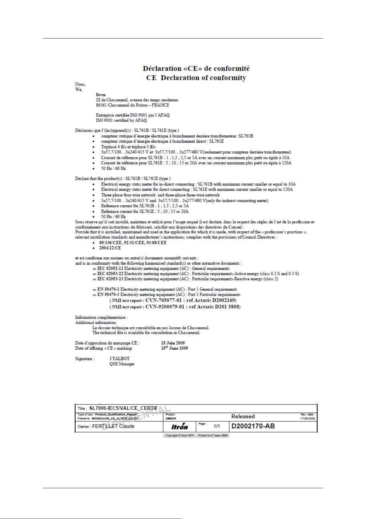
2.2. CE Certificate of conformity
TO BE UPDATED
2.3. End-of-life disposal
SL7000 RT meters comply with the requirements of WEEE regulations for recycling or reuse of materials.
At the end of their service life, meters should be uninstalled and then passed to a licenced/certified contractor for
7
Page 12

Installation Guide SL7000 RT
D2021471
-AA
disposal in accordance with these regulations and with all applicable local regulations.
Before passing the meters to the contractor the legal certification stamps or marks must be removed or defaced.
8
Page 13

Installation Guide SL7000 RT
D2021471
-AA
Page intentionally left blank
9
Page 14

D2021471
-AA
3. Safety information
Meters must be installed and maintained only by suitably-qualified personnel. Observe the following safety advice
when performing installation or service work on meters.
Meter handling
Before installing or removing a meter, or removing the terminal cover for any reason, isolate the
meter from the mains supply by removing the supply-side fuses or using alternative local
arrangements. Take appropriate measures to ensure that the isolation cannot be overridden by
another person. For example, keep physical possession of the supply fuses.
• Adhere strictly to all relevant national regulations for the avoidance of electrical accidents.
• Always disconnect all measurement and auxiliary circuit connections from the meter before
attempting to open the meter housing.
• Use only tools that have been approved for electrical installations.
• Clean meters only with a damp cloth or sponge. Do not use excessive or running water.
Installation
Install meters in accordance with the voltage and current specifications printed on the front panel and
the wire and environmental specifications given in the installation information.
• The meter measuring and auxiliary circuits must be galvanically isolated.
Installation Guide SL7000 RT
• All voltage paths (measurement and auxiliary) must be fused.
• The meter voltage connections must be physically separated from the communication lines
in accordance with local laws and regulations.
• Do not install meters that are obviously damaged.
• Do not install meters that have been dropped or otherwise subjected to significant impact
even if no damage can be seen.
• Do not HIPOT/Dielectric test the auxiliary or communication circuit connections.
• Do not use any meter functions or features for primary protection purposes.
• Do not install meters where failure of the device could cause death, injury or release
sufficient energy to start a fire.
• Following installation, ensure that the meter terminal covers are correctly fitted and sealed
to prevent user access.
10
Page 15

Installation Guide SL7000 RT
D2021471
-AA
Page intentionally left blank
11
Page 16

D2021471
-AA
4. General information
4.1. Meter overview
Depending on the factory configuration, the meter provides the following minimum features and functions:
Installation Guide SL7000 RT
The SL7000 RT is a static, polyphase, four-quadrant, multi-rate
meter. It is intended for monitoring of MV/LV substations on their
LV side.
Multi-energy registering Active, Reactive and Apparent energy (import and export)
Units - Watt (W), Kilowatt (kW) and Megawatt (MW)
Maximum 32 individual energy rate registers for 10 energy channels
(incremental or cumulative)
Up to 8 energy rates per channel
Multi-rate billing and switching Billing for both energy and demand
Energy rate switching performed by internal clock/calendar
• Up to 12 seasons
• Up to 24 day profiles
• Up to 16 switching times per day profile
• Up to 100 special days (repetitive or non-repetitive)
Demand registering Maximum 24 individual demand rate registers for 10 demand channels
Up to 8 energy rates per channel
Load profiling 2 independent sets of 8 recording channels giving up to 16 load profile channels
Incremental data
Communication RS232 + RS232 or RS485
DLMS-Cosem compliant
PSTN, LAN (TCP/IP), GSM and GPRS media supported
Network quality monitoring Voltage cuts, sags and swells
Total Harmonic Distortion (THD)
12
Page 17

Installation Guide SL7000 RT
D2021471
-AA
The diagram below shows the main functional elements of the meter:
1 Liquid crystal display (LCD)
2 Infrared communication port
3 Auxiliary I/O terminal blocks
4 Main wiring terminal block
5 Reactive power metrology LED (Rlq)
6 Active power metrology LED (Rlp)
7 Display pushbutton
8 Reset pushbutton
9 Battery holder
10 Serial communication ports
4.2. General specifications
Frequency 50/60 Hz
Connection wiring 4 wires
Connection configuration Rogowski sensors
Terminal wiring Current sensors presassembled – Voltages 3Ph+N
Real Time Clock backup Field-replaceable battery and Internal super-capacitor
Enclosure type Panel mounting DIN compliant
Environmental protection IP 51
Operating temperature Storage : -40°C to +70°C
Relative Humidity < 75% (maximum 95%)
Net weight 1.9kg
Maximum meter dimensions (W x H x D)
Meter body 179 x 261 x 83mm
With short terminal cover 179 x 270 x 83mm
With long terminal cover 179 x 359 x 83mm
Standard terminal cover 179 x 324 x 83mm
13
Page 18

Installation Guide SL7000 RT
D2021471
-AA
Connection specifications
Voltage 3 x 127/220V up to 3 x 277/480V auto ranging
Current Nominal (Ib) Ib: 300A
Maximum (Imax) Imax : 3000A at 50Hz
2500A at 60Hz
Global accuracy
(current sensors included)
Active energy Class 1
Reactive energy Class 1 or 2
Auxiliary power supply specifications (optional)
Auxiliary Power Supply 48V DC to 145V DC
48V AC to 288V AC
4.3. Meter support tools
The SL7000 RT meters have an extensive range of optional facilities and settings, enabling them to be
configured to suit individual requirements. In general, a meter is fully configured and programmed for its intended
application prior to despatch from the factory.
However, some aspects of the configuration may be changed at any time using dedicated Windows™-based
support tools that typically communicate via the optical port on the front of the meter.
Support tool applications provide the following main features:
• metering point management
• configuration creation and editing
• configuration programming and reading
• meter data reading
• meter firmware upgrading
The following support tool is currently available:
ACE Pilot
ACE Pilot is compliant with the following Microsoft Windows™ operating systems:
• XP (SP3)
• 2003 and 2008
• Vista and Seven
4.4. Configuration options
4.4.1. Meter identification
Meter options are specified by a multi-character product code, in which each option is designated by one or more
characters. The meter cover is laser-marked with this legally required identification code.
14
Page 19

D2021471
-AA
4.4.2. Meter product coding
The meter is equipped with input and output (I/O) ports, as shown:
I/O Number
Control inputs 2
Pulse inputs 4
Control outputs 4
Pulse inputs 6
1st COM port RS232 or RS485
2nd COM port RS232
Product code
The example below illustrates the options and the positions of the associated characters in the product code.
Installation Guide SL7000 RT
The following tables provide full details of the individual options:
Product version
Code Option
1 International
Connection and Class
Code Option
R Rogowski - Global Class 1
I/O and COM configuration
Code Option I/O Level
06 2 x RS232 Full
07 1 x RS232 + 1 x RS485 Full
08 2 x RS485 Full
Auxiliary Power Supply (APS)
Code Option
0 No APS
1 APS fitted
Note: Legal product code is composed of “SL76” + “product version” + “Connection and class”. Following
numbers composing the product code are not legal part (for internal and market use only).
15
Page 20

Installation Guide SL7000 RT
D2021471
-AA
4.5. Meter markings
The meter cover is laser-marked with at least the information illustrated below, in accordance with IEC 62053-52.
Additional markings may be present, and the layout of the markings will vary, according to the meter
configuration and specific customer requirements.
1 Manufacturer name
2 Commercial name
3 Nominal voltage
4 Nominal / maximum current and frequency
5 Metrology constant and accuracy class
6 Appropriate symbols (IEC 62053-52) identifying insulation class, measuring elements, and
other relevant characteristics
7 Manufacturers unique serial number
8 Meter legal product code and date of manufacture
9 Place of manufacture
10 Meter serial number - barcode and numerical format
This number may be the same as the manufacturers serial number (7) or be a customerspecified identification number
16
Page 21

D2021471
-AA
4.5.1. Terminal numbering
A connection diagram is displayed on the inside surface of the terminal cover showing typical main supply
connections for the meter configuration and type.
Terminal numbers corresponding to the connection diagram are moulded into the meter case, either above or
below the terminal block depending on the meter connection type.
Rogowski terminal block
Installation Guide SL7000 RT
17
Page 22

D2021471
-AA
5. Technical specification
General
Parameter Description Data
Meter Commercial Name SL7000 RT
Connection wiring 3 or 4 wires
Connection configuration Rogowski
Installation Guide SL7000 RT
Terminal wiring Voltage only
Rogowski current sensors are
irremovable (already attached to the
meter body)
Metrology Four quadrant Active and Reactive
(import and export)
Metrology sensors Rogowski derivative ironless sensors
(split type flexible loops)
Registering modes 4 selectable algorithms Ferraris
Static
Net result
Anti-fraud
Global Accuracy (Rogowski sensors
included)
i.a.w. EN/IEC62053-21 Class 1 for active energy
Voltage
Parameter Details
Reference voltage 3 x 127/220V up to 3 x 277/480V
auto ranging
Operating voltage -20% to + 15% Un
Voltage Interruptions 1 second
Current
Parameter Details
Nominal current (Ib) 300A
Maximum current (Imax) 3000A at 50Hz
2500A at 60Hz
Starting current 1.2 A (Ib/250) , per phase
Short-time over current Not limited by the SL7000 RT
Current Circuit Power Consumption Not applicable
Voltage Circuit Power Consumption
Parameter Details
Voltage per phase <2W
Apparent power per phase at Un <10VA
18
Page 23

Installation Guide SL7000 RT
D2021471
-AA
Display
Parameter Description Data
Type Liquid Crystal Display (LCD)
Digit height Main 12mm
Digit height OBIS code 8mm
Resolution Number of digits 9
Communications
Parameter Description Data
Optical communications i.a.w IEC62052-21 Mode C
Meter Constant Rogowski connection type 40 pulses per kWh
Serial Data Communications RS232, and RS232 or RS485 RJ45 connectors
Baud rate 9600 up to 19200
Supported protocols DLMS/Cosem Y
Communication media types TCP With external LAN modem
GPRS With external modem
GSM With external modem
Real-time operation “Real Time Port” i.a.w. IEC62056-21 Y
Modem power supply 10V -10/+20%, 100mA, 1W max on RJ45 connectors. 1W is the
maximum shared on the 2 ports
Input and output
Parameter Description Data
Control input Optically-isolated, high-level Up to 2 inputs + common
connection point
Minimum input voltage 64V (AC/DC)
Maximum input voltage 288V DC - 300V AC
Maximum input current 3mA
Control output Optically-isolated, high-level Up to 4 outputs + common
connection point
Maximum switching voltage 288V DC - 300V AC
Maximum switching current 100mA
Pulse input (DIN S0) Optically-isolated Up to 6 inputs + common
connection point
Maximum switching voltage 27V DC
(provided by the meter)
Maximum switching current 30mA
Impedance
1.1kΩ
Pulse output (DIN S0) Optically-isolated Up to 4 outputs + common
connection point
Impedance
19
< 300Ω
Page 24

Installation Guide SL7000 RT
D2021471
-AA
-
40°C
to +70°
C
Environmental
Parameter Description Data
Temperature Range Operating range
Humidity range Maximum operating value 95%
Protection class According to IEC 60529 IP 51
Isolation Protection AC voltage at 50Hz for 1 minute 4kV Class 2
Immunity to impulse voltage According to IEC 62052-11
8kV
Waveform of pulse voltage
1.2/50µsecs
Source impedance 500ohms, energy
0.5 joules
Immunity to magnetic fields Magnetic AC (50Hz) field 0.5mT
Fully immune
according to IEC62053 - 21 (400AT
coil)
Magnetic DC field according to IEC
Fully immune
62053-21 (electromagnet with
1000AT)
Magnetic DC field according to
Fully immune
VDEW (perm magnet) field strength
200mT
1.2 Tesla DC Magnets Fully immune
Surge immunity
main circuits
Surge immunity
auxiliary circuits
Electrostatic discharge Electrostatic discharge according to
According to IEC61000-4-5
Source impedance 2 ohms
According to IEC61000-4-5
Source impedance 42 ohms
4kV
1kV
IEC61000-4-2
Contact discharge 8kV, 10 cycles
Air discharge 15kV, 10 cycles
Immunity to RF fields RF fields i.a.w. IEC61000-4-3
With current
10V/m
80MHz to 2GHz
Without current,
30V/m
80MHz to 2GHz
Fast transient burst
Main circuits : Fast transient burst
i.a.w. IEC 61000-4-4
4kV
common-mode and pseudo
differential
Auxiliary circuits : Fast transient
burst i.a.w. IEC 61000-4-4
2kV
common-mode
Radio Interference RF suppression CISPR22 Class B
20
Page 25

Installation Guide SL7000 RT
D2021471
-AA
Weight and Dimensions
Parameter Description Data
Weight 1.9kg nominal
Dimensions
Without terminal cover 179 x 261 x 83mm
(width x height x depth)
With short terminal cover 179 x 270 x 83mm
With long terminal cover 179 x 359 x 83mm
With standard terminal cover 179 x 324 x 83mm
Rogowski sensors Aperture for the primary conductor 120 mm diameter
Thickness of the loop 5 mm diameter
Weight (loop only) 40 g
Cable length 3 m between the loop itself and
the meter body
21
Page 26

D2021471
-AA
6. Technical description
Rogowski
The main components of the SL7000 meter are assembled onto four printed circuit boards (PCBs):
• metrology voltage divider circuitry and the switched-mode power supply
• microcontroller and memory devices
• I/O circuitry
• LCD display
As a manufacturing option, the meter may be equipped with an additional PCB providing further serial
communication ports.
The block diagram below shows the main functional elements of the meter.
Installation Guide SL7000 RT
22
Page 27

Installation Guide SL7000 RT
D2021471
-AA
6.1. Metrology
The SL7000 RT uses Rogowski loops as current sensors, instead of MCT that are used in the conventional
SL7000 CT or DC.
Rogowski loops are based on Ampère’s law stating that the integral value of the magnetic field over any closed
path surrounding a current conductor is related to the amount of current flowing through this path.
A Rogowski sensor delivers a voltage strictly proportional to the derivative value of the current(s) embraced. So
their output is equivalent to the MCT sensors.
The SL7000 RT meters are calibrated in the factory with their Rogowski loops attached, as shipped, so no
additional calibration is required in the field.
The Rogowski sensors used by the SL7000 RT can be installed over current cables easily thanks to its quick clipon system. Their dynamic range allows using a unique model addressing installations rated from 200kVA to
2MVA.
The three current sensors generate a signal per phase that is proportional to the instantaneous current, while
voltage signals are derived by dividing the distribution-network line voltages through a resistive divider.
The current and voltage input signals are sampled and digitised 40 times per cycle (50Hz) by an analogue to
digital (A-to-D) converter, then processed by a microcontroller to derive various energy values. The
microcontroller records these values in a suite of registers that are independent of any meter configuration and
are always available.
These registers accumulate their respective energy values in an incremental fashion, until they reach the register
limit. At that point they are automatically reset to zero in the same way as roll-over electromechanical meter
types.
The contents of these registers can be displayed at any time as instantaneous values on the meter LCD.
The microcontroller also controls the data transfer to the various inputs and outputs, visible metrological LEDs
and infrared port.
Refer to the SL7000 User Guide for more technical description.
23
Page 28

D2021471
-AA
7. Communications
Refer to the SL7000 User Guide
Installation Guide SL7000 RT
24
Page 29

D2021471
-AA
8. Meter displays
Refer to the SL7000 User Guide.
Installation Guide SL7000 RT
25
Page 30

D2021471
-AA
9. Installation
9.1. Warnings
DANGER OF ELECTRIC SHOCK
Before and during installation of a meter, observe all requirements given in the Safety information.
In particular:
Installation Guide SL7000 RT
• Meters must be installed only by suitably-qualified personnel.
• Ensure that the meter supply cabling is isolated from the mains supply, and that the
isolation cannot be overridden by another person.
• Following installation, ensure that the meter covers are correctly fitted and sealed to
prevent user access.
DANGER OF ELECTRIC SHOCK
The SL7000 RT meter is designed for live installation on isolated primary conductors or cables in
low voltage (not exceeding 500V).
In case of installation on bare conductors or bars systems, an additional isolation of the conductors
or bars must be recovered at the location intended for the Rogowski loops prior of their installation.
9.2. Environmental
SL7000 RT meters are certified for indoor use only. Do not install meters outdoors unless they are housed in an
enclosure which can maintain the specified environmental requirements.
Parameter Range
Temperature -40° to +70°
Humidity Up to 95% RH
Environmental protection IP 51
9.3. Dimensions
The meter can be factory-fitted with either a short, standard or long terminal cover.
26
Page 31

Installation Guide SL7000 RT
D2021471
-AA
Item Dimension Description
A 179 Meter body width
B 270 Meter length - with short terminal cover
324 Meter length - with standard terminal cover
359 Meter length - with long terminal cover
C 83 Meter body depth
All dimensions are in millimetres.
9.4. Fixings
The meter is provided with two upper fixing points (1) and (2), select the appropriate one to use, as required. A
hanging bracket is also provided with the meter.
Two further lower fixing points are located within the terminal area; these can be accessed only by removing the
terminal cover.
27
Page 32

Descriptio
Upper fixing point (1) to lower fixing points (centre to centre)
Upper fixing point (2) to lower fixing points (centre to centre)
Left to right lower fixing points (centre to centre)
Upper fixing point (1) centre to lower edge
Lower edge of meter body to lower edge of short terminal cover
Lower edge of meter body to lower edge of standard terminal cover
Lower edge of meter body to lower edge of long terminal cover
All dimensions are in millimetre
Installation Guide SL7000 RT
D2021471
-AA
Item Dimension
A 230
B 201
C 150
D 252
E 4
E 58
E 93
n
of meter body
s.
28
Page 33

Installation Guide SL7000 RT
D2021471
-AA
9.5. Auxiliary and communication wiring
Auxiliary wiring
Terminal Function Terminal Function Terminal Function
20 Control output 1 29 Pulse output 1 36 Pulse input 1
21 Control output 2 30 Pulse output 2 37 Pulse input 2
22 Control output 3 31 Pulse output 3 38 Pulse input 3
23 Control output 4 32 Pulse output 4 39 Pulse input 4
24 No connection 33 Pulse output 5 40 PI Common
25 CO Common 34 Pulse output 6
26 Control input 1 35 PO Common
27 Control input 2
28 CI Common
The control output and input terminal blocks accept cables up to 2.5mm².
The pulse output and input terminal blocks accept cables up to 1.5mm².
Note: Depending on meter factory configuration, some of the inputs and outputs shown above may not be
available.
Communication wiring
Both RS232 and RS485 type communication ports use RJ45 connectors:
It is recommended that twisted and shielded cables are used for communication line wiring and that one end of
the cable shield should be connected to ground.
Pin RS232 Function RS485 Function
1 VMDM Approx +10V DC at 100mA (0.9W max) VMDM Approx +10V DC at 100mA (0.9W max)
2 No connection RX -
3 No connection No connection
4 RX RX +
5 TX TX +
6 0V - Ground 0V - Ground
7 DTR TX -
8 No connection No connection
29
Page 34

Installation Guide SL7000 RT
D2021471
-AA
9.6. Cabling
Main terminal wiring - voltage connection
Terminal Function Terminal Function Terminal Function Terminal Function
1 Not used 4 I3 sensor 7 U1 11 Neutral
2 I1 sensor 5 Not used 8 U2 14 APS
3 I2 sensor 6 Not used 9 U3 15 APS
Main terminal specification
Terminal type Clamp screws Cable diameter
Voltage 2 x M4 5mm (max)
Current sensors Factory set – No need to manipulate
30
Page 35

Installation Guide SL7000 RT
D2021471
-AA
Installation of the Rogowski loops over the main power cable(s)
1.
1. The 3 Rogowski loops are marked by a colored
sleeve close to their junction block.
• Grey for phase 1 sensor
• Brown for phase 2 sensor
• Black for phase 3 sensor
It is key that the Rogowski sensors are installed
accordingly their corresponding phase otherwise the
measurement will be mixed up.
2. The junction block of the Rogowski loop bears a
direction arrow.
Make sure that the loop is installed in such a way
that :
Network
• The arrow is located at the inner side of the
loop (do not force thenatural curvature of
the lop in the opposite way)
Colored
sleeve
Load
• The arrow points towards the LOAD side
It is key that the direction of the Rogowski sensors is
correct, otherwise the measurement will be reversed
(import for export and vice-versa).
3. General recommendations
• When securing the loop part against the main conductor or cable, a moderate pressure is sufficient
thanks to the light weight of the sensor, do not flatten the loop part
• As far as possible, keep the loop part away from adjacent conductors (the other phases for instance)
31
Page 36

Installation Guide SL7000 RT
D2021471
-AA
9.7. Battery
The meter is designed so the lithium battery can be safely installed or replaced while the meter is operating, as
follows:
1. If fitted, remove the seal from the battery holder securing screw.
2. Undo the securing screw and carefully extract the battery holder from the meter housing.
3. The meter may be initially shipped with the battery cable in the disconnected position (1). If this is the case,
move and fit the cable connector into the moulded pillar, as shown (2).
The illustrations show a rear view of the battery holder.
4. If the battery is being replaced, slide the old one out from under the securing tab and exchange.
5. Ensure the battery connector is the correct way round, as shown above.
6. Replace the battery holder into the meter, ensuring the moulded plastic connector pillar is inserted into the
lower aperture.
7. Tighten front securing screw.
8. Using the meter support tool, clear any battery error indications/alarms and reset the battery expected life
time value.
9. Seal the meter, as necessary.
9.8. Installation checks
Before connecting the mains supply to the installed meter, carefully check that:
• the correct meter type with the right identification number has been installed for this client at this metering
point.
• all mains supply and auxiliary cables are connected to the correct terminals.
• all cable clamp screws are securely tightened.
• the battery has been correctly installed.
32
Page 37

Installation Guide SL7000 RT
D2021471
-AA
9.9. Start-up and functional checks
Take the following steps to check that the meter is functioning.
1. Connect the mains supply to the meter.
2. Check that the LCD display turns on and shows coherent displays.
Depending on the meter configuration, the LCD may move automatically through a sequence of displays, or
it may be necessary to use the meter display pushbutton to move through the sequence.
3. Check that the meter is in the start mode (STOP is not displayed).
4. Check the phase sequence is correct; the quadrant indicator icons in the LCD should not be flashing.
5. Apply a load to the meter and check that the metrology LED (active - kWh) starts to flash.
The flash rate is proportional to the load.
6. Using the IR port, connect a support tool enabled PC to the meter and:
• read the Total Energy Registers (TER) values
• read all instantaneous values
• read the meter status values and its configuration
• erase any non-fatal alarms
7. Carry out the LCD test and confirm all the display segments and annunciator icons are lit.
8. Wait for approx 15 minutes while the meter operates.
9. Check the TER values have incremented from their initial values.
10. Check the maximum demand value is consistent with the applied load.
11. Re-check meter status.
9.10. Metrology parameters settings
With the ACE Pilot support tool, open the meter configuration
1. Make surre that the General Ressources are set for a SL7000 with: Meter Type SL761, FW Version 9.xx and
Meter connection Transformer
2. Make sure that the Metrology Connection parameters are set to a CT ratio 250/1 and a VT ratio 1/1
3. Make sure that the Metrology/Network parameters are set to 12 A Max Current
The Maximum Usual current may be set to a lower value depending on the application.
4. Use the Toolbox functions to verify all aspects of meter operation.
5. Save and print the results as evidence of correct operation.
33
Page 38

Installation Guide SL7000 RT
D2021471
-AA
9.11. Sealing the meter
Before leaving the installation site, fit the terminal cover, and seal the meter against unauthorised access or
tampering by fitting wire or plastic seals, as required, in the following locations:
1 IR Port
2 Reset pushbutton
3 Battery holder
4 Main cover
5 Terminal cover
9.12. Current conductors environment recommendations
TO BE DEVELOPPED
34
Page 39

Installation Guide SL7000 RT
D2021471
-AA
Page intentionally left blank
35
Page 40

D2021471
-AA
10. Technical appendix
Refer to SL7000 User Guide
Installation Guide SL7000 RT
36
 Loading...