

Page 1

OpenWay® Riva CAM3
Installation Guide
Technical
Communications
knowledge to shape your future
Page 2

Identification
OpenWay® Riva CAM3 Installation Guide
7 November 2018
TDC-7086-000
Copyright
© 2018 Itron, Inc. All rights reserved.
Confidentiality Notice
The information contained herein is proprietary and confidential and is being provided
subject to the condition that (i) it be held in confidence except to the extent required
otherwise by law and (ii) it will be used only for the purposes described herein. Any third
party that is given access to this information shall be similarly bound in writing.
Trademark Notice
Itron is a registered trademark of Itron, Inc.
All other product names and logos in this documentation are used for identification purposes
only and may be trademarks or registered trademarks of their respective companies.
Suggestions
For more information about Itron or Itron products, see www.itron.com.
If you have questions or comments about the software or hardware product, contact Itron
Technical Support Services.
Contact
• Email: support@itron.com
• Itron Access: https://support.itron.com
• Telephone Itron Technical Support North America: 1-877-487-6602
For technical support contact information by region, go to www.itron.com and select your
country and language.
Page 3

Contents
Chapter 1 Overview.............................................................................................1
Regulatory Compliance........................................................................................................................................ 1
Chapter 2 Installation Kits.................................................................................. 5
CAM3 Installation Kit............................................................................................................................................ 5
RF Filter Kit........................................................................................................................................................... 5
External Antennas................................................................................................................................................. 5
915 MHz 5.5 dBi External Antenna Kit.......................................................................................................5
915 MHz 8.15 dBi External Antenna Kit.....................................................................................................6
Remote-Mount High-Gain (8.15 dBi) 915 MHz Antenna for CGR/CAM3.................................................. 6
915 MHz Antenna Specications........................................................................................................7
Chapter 3 CAM3 Installation for RF-Only Applications................................... 9
Disconnecting CGR Power................................................................................................................................... 9
Installing the CAM3 for RF-Only Applications.................................................................................................... 12
Chapter 4 ACTD Application Installation........................................................ 15
Chapter 5 External Antenna Installation......................................................... 17
External Antenna Only........................................................................................................................................ 17
Disconnecting the CGR Cables............................................................................................................... 18
Unmounting the CGR...............................................................................................................................21
Removing the CGR Mounting Bracket.....................................................................................................21
Installing the CGR Mounting Bracket.......................................................................................................22
Installing the CGR.................................................................................................................................... 23
Reconnecting the CGR Cables................................................................................................................ 24
Assembling the Antenna.......................................................................................................................... 26
External Antenna with RF Filter...........................................................................................................................28
Disconnecting the CGR Cables............................................................................................................... 30
Unmounting the CGR...............................................................................................................................33
Removing the CGR Mounting Bracket.....................................................................................................33
Installing the RF Filter Mounting Bracket.................................................................................................34
Installing the CGR Mounting Bracket.......................................................................................................35
Installing the CGR.................................................................................................................................... 36
Connecting the RF Filter Cables.............................................................................................................. 37
Reconnecting the CGR Cables................................................................................................................ 38
Assembling the Antenna.......................................................................................................................... 40
Lightning Arrestor............................................................................................................................................... 42
Weatherproong the RF Connections.................................................................................................................43
Chapter 6 Field Replacement...........................................................................46
Requirements......................................................................................................................................................46
Uninstalling the Existing CAM.............................................................................................................................46
Opening the CGR.....................................................................................................................................47
OpenWay® Riva CAM3 Installation Guide iii
Proprietary and Confidential
Page 4

Door Sensor...................................................................................................................................... 47
Connecting to the CGR............................................................................................................................48
Conrming the CAM Slot Location.......................................................................................................... 50
Powering Down the CAM.........................................................................................................................51
Verifying the CAM Location......................................................................................................................51
Removing the CAM.................................................................................................................................. 52
Installing the New CAM3.................................................................................................................................... 53
Powering Up the CAM3........................................................................................................................... 53
Conrming the CAM3 Status................................................................................................................... 54
Ending the CGR PuTTY Connection........................................................................................................ 55
Closing the CGR...................................................................................................................................... 55
OpenWay® Riva CAM3 Installation Guide iv
Proprietary and Confidential
Page 5

Chapter 1 Overview
This document provides the procedure necessary to install the CGR ACT Module 3 (CAM3)
in the 1000 Series Cisco® Connected Grid Router (CGR). In addition to the physical
installation of the Adaptive Communications Technology (ACT) module, a procedure for
loading the ACTD application into the CGR Guest Operating System (GOS) is also
provided. The ACTD application serves as a communication gateway between the CGR
operating system (IOS) and the CAM3. A procedure for the installation of an external
antenna is also included. An external antenna is required to ensure optimal radio
performance when the CGR is deployed in a star configuration for battery-powered-device
(BPD) deployments.
This document is intended for field installers who are familiar with the CGR, its function, and
operation. The information in this document is complementary to the base CGR installation
procedures and addresses the addition of the CAM3/ACTD and the external star network
antenna.
For further information about the base CGR installation, refer to the Cisco 1240 Connected
Grid Router Hardware Installation Guide.
Regulatory Compliance
Labeling
The following information appears on labels on the exterior of the CGR.
• FCC ID: LDKALTMT0556
• IC: 2461B-ALTMT0556
• Model: CGR1240
Contains:
• FCC ID: EO9OW3
• IC: 864A-OW3
• Model: OW3
• Model Name: CAM3
• FCC ID: N7NMC7355
• IC: 2417C-MC7355
• Model: MC7354
The following information may also appear on an exterior label:
"This device complies with Part 15 of the FCC Rules. Operation is subject to the following
two conditions: (1) this device may not cause harmful interference, and (2) this device must
accept any interference received, including interference that may cause undesired
operation."
OpenWay® Riva CAM3 Installation Guide 1
Proprietary and Confidential
Page 6

Overview
FCC Compliance
This device complies with Part 15 of the FCC Rules. These limits are designed to provide
reasonable protection against harmful interference in a residential installation. Operation is
subject to the following two conditions:
• This device may not cause harmful interference.
• This device must accept any interference that may cause undesirable operation.
This device must be installed to provide a separation distance of at least 20 centimeters (7.9
inches) from all persons to be compliant with regulatory RF exposure.
USA FCC Part 15, Class B
This equipment has been tested and found to comply with the limits for a Class B digital
device, pursuant to Part 15 of the FCC Rules. These limits are designed to provide
reasonable protection against harmful interference in a residential installation. This
equipment generates uses and can radiate radio frequency energy and, if not installed and
used in accordance with the instructions, may cause harmful interference to radio
communications. However, there is no guarantee that interference will not occur in a
particular installation. If this equipment does cause harmful interference to radio or television
reception, which can be determined by turning the equipment off and on, the user is
encouraged to try to correct the interference by one or more of the following measures:
• Reorient or relocate the receiving antenna.
• Increase the separation between the equipment and receiver.
• Connect the equipment into an outlet on a circuit different from that to which the receiver
is connected.
• Consult the dealer or an experienced radio/TV technician for help.
Caution: To ensure system performance, this device and antenna shall not be
changed or modified without the express approval of Itron. Per FCC rules,
unapproved modifications or operation beyond or in conflict with these instructions
for use could void the user's authority to operate the equipment.
Canada ISED (Innovation, Science and Economic Development)
Compliance
This device contains license-exempt transmitter(s)/receiver(s) that comply with Innovation,
Science and Economic Development Canada’s license-exempt RSS(s). Operation is subject
to the following two conditions:
1.
This device may not cause interference.
2. This device must accept any interference, including interference that may cause
undesired operation of the device.
L’émetteur/récepteur exempt de licence contenu dans le présent appareil est conforme aux
CNR d’Innovation, Sciences et Développement économique Canada applicables aux
OpenWay® Riva CAM3 Installation Guide 2
Proprietary and Confidential
Page 7

Overview
appareils radio exempts de licence. L’exploitation est autorisée aux deux conditions
suivantes :
1. L’appareil ne doit pas produire de brouillage.
2. L’appareil doit accepter tout brouillage radioélectrique subi, même si le brouillage est
susceptible d’en compromettre le fonctionnement.
Under Innovation, Science and Economic Development Canada regulations, this radio
transmitter may only operate using an antenna of a type and maximum (or lesser) gain
approved for the transmitter by Innovation, Science and Economic Development Canada.
To reduce potential radio interference to other users, the antenna type and its gain should
be so chosen that the equivalent isotropically radiated power (e.i.r.p.) is not more than that
necessary for successful communication.
Conformément à la réglementation d'Industrie Canada, le présent émetteur radio peut
fonctionner avec une antenne d'un type et d'un gain maximal (ou inférieur) approuvé pour
l'émetteur par Industrie Canada. Dans le but de réduire les risques de brouillage
radioélectrique à l'intention des autres utilisateurs, il faut choisir le type d'antenne et son
gain de sorte que la puissance isotrope rayonnée équivalente (p.i.r.e.) ne dépasse pas
l'intensité nécessaire à l'établissement d'une communication satisfaisante.
The radio transmitter (IC: 864A-OW3) has been approved by Innovation, Science and
Economic Development Canada (ISED) to operate with the antenna types listed previously
with the maximum permissible gain and required antenna impedance for each antenna type
indicated. Antenna types not included in this list, having a gain greater than the maximum
gain indicated for that type, are strictly prohibited for use with this device.
Le présent émetteur radio (IC: 864A-OW3) est conforme aux CNR d'Industrie Canada pour
fonctionner avec les types d'antenne énumérés ci-dessus et ayant un gain admissible
maximal et l'impédance requise pour chaque type d'antenne. Les types d'antenne non
inclus dans cette liste, ou dont le gain est supérieur au gain maximal indiqué, sont
strictement interdits pour l'exploitation de l'émetteur.
RF Exposure (FCC/ISED)
This equipment complies with radiation exposure limits set forth for an uncontrolled
environment. This equipment should be installed and operated with minimum distance of 20
cm between this device’s radiators and your body. These transmitters must not be colocated or operating in conjunction with any other antennas or transmitters, that are not part
of the CGR Host router and CAM3 module.
Cet équipement est conforme aux limites d'exposition aux radiations définies pour un
environnement non contrôlé. Cet équipement doit être installé et utilisé à une distance
minimale de 20 cm entre les radiateurs de l'appareil et votre corps. d’autres antennes ou
émetteurs ne faisant pas partie du routeur hôte CGR et du module CAM3.
OpenWay® Riva CAM3 Installation Guide 3
Proprietary and Confidential
Page 8

Overview
Professional Installation
These antennas are intended for professional installation by the integrator. The OEM
integrator is still responsible for the FCC compliance requirement of the end product, which
integrates this antenna.
Modification and Repairs
To ensure FCC compliance and system performance, this device, antenna and/or coaxial
assembly shall not be changed or modified without the express written approval of Itron.
Any unauthorized modification will void the user’s authority to operate the equipment.
DANGER: This device contains no user serviceable parts. Attempts to repair this
device by unauthorized personnel may subject the person to shock hazard if
removal of protected covers is attempted. Unauthorized repair will void the warranty
and/or maintenance contract with your company.
Electromagnetic Compatibility
Caution: Use only approved accessories with this equipment. All cables must be
high quality, shielded, and correctly terminated. Unapproved modifications or
operation beyond or in conflict with these use instructions may void the authority's
authorization to operate the equipment.
OpenWay® Riva CAM3 Installation Guide 4
Proprietary and Confidential
Page 9

Chapter 2 Installation Kits
This section lists the installation kits available to aid installation.
Notice: In accordance with FCC rules, unapproved modifications or operation beyond or in
conflict with these use instructions could void the user's authority to operate the equipment.
Only authorized Itron personnel may open the ERT Gateway. Unauthorized access or
modifications to the ERT Gateway will void the warranty.
CAM3 Installation Kit
The following items are included in the CAM3 installation kit:
• 1 CGR ACT module
• 1 Regulatory label
RF Filter Kit
The following items are included in the RF Filter installation kit:
• Mounting bracket
• CGR to RF Filter cable
• RF Filter
• Lightning arrestor
External Antennas
This equipment has been designed and approved per FCC rules to operate with these CAM
antennas. The required antenna impedance is 50Ω. To reduce potential radio interference to
other users, the antenna type and its gain were chosen so that the equivalent isotropically
radiated power (EIRP) is not more than that permitted for successful communication.
Caution: Antennas not approved by Itron are strictly prohibited for use with this
device. Installing the CAM with an unapproved antenna will void the product
warranty and can void the user's authority to operate this equipment.
915 MHz 5.5 dBi Exter
The following items are included in the External Antenna installation kit (KIT-0049-001):
• 915 MHz 5.5 dBi gain antenna
• Antenna mounting kit:
◦ Remote mount adapter
OpenWay® Riva CAM3 Installation Guide 5
nal Antenna Kit
Proprietary and Confidential
Page 10

Installation Kits
◦ Antenna holder
◦ Mounting bracket
◦ 6-inch bolts (4)
◦ 1¾-inch bolts (2)
◦ Flat washers (6)
◦ Split washers (6)
◦ Nuts (6)
◦ Pipe clamp hangers (2)
◦ Silicone seal
◦ Anti-seize lubricant
Caution: Do not install a 5.5 dBi antenna directly on the CGR/CAM3. Antenna
installation directly on the CGR/CAM3 will compromise mechanical integrity and will
not meet the compliance requirements.
915 MHz 8.15 dBi External Antenna Kit
The following items are included in the External Antenna installation kit (KIT-0018-007):
• 915 MHz 8.15 dBi gain antenna
• Antenna mounting kit:
◦ Thermal ring
◦ Lightning Arrestor
◦ Mounting bracket (BAM1005)
Caution: Do not install an 8.15 dBi antenna directly on the CGR/CAM3. Antenna
installation directly on the CGR/CAM3 will compromise mechanical integrity and will
not meet the compliance requirement for a loss of 3.0 dB between the CAM3 and
the 8.15 dBi antenna.
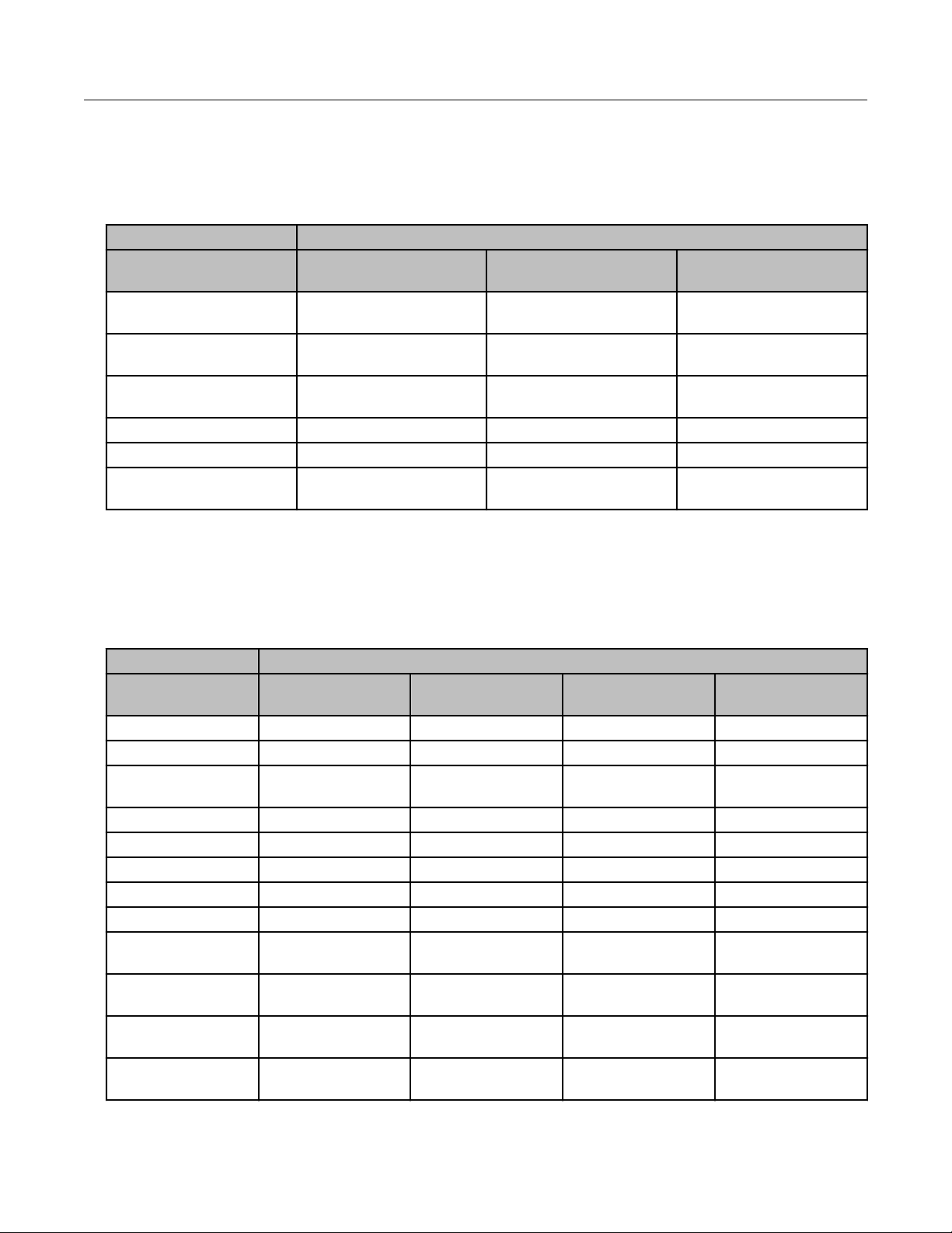
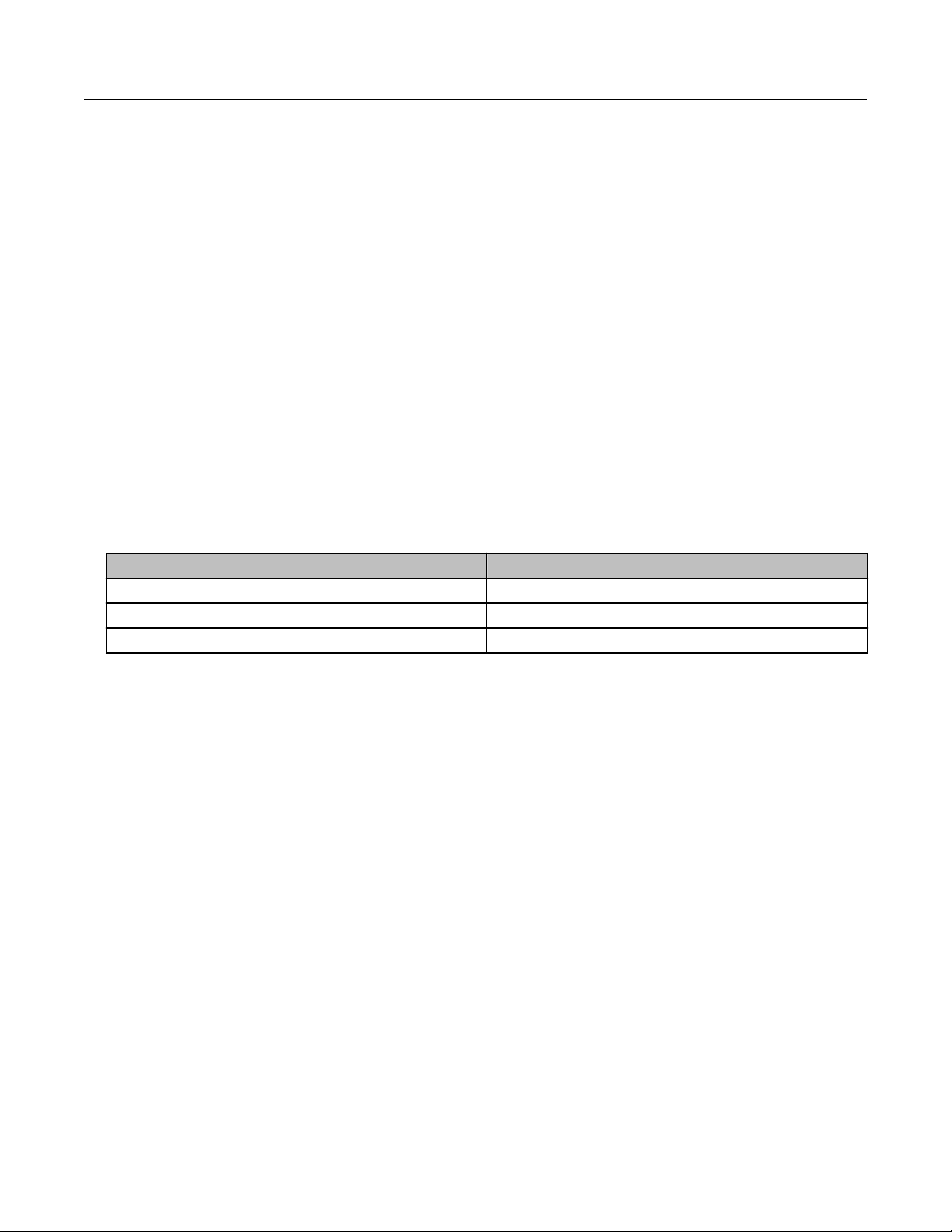
Remote-Mount High-Gain (8.15 dBi) 915 MHz Antenna for
CGR/CAM3
The following coax specification table lists several options for coaxial cable that can be used
with the remote-mount high-gain 915 MHz antenna. When a high-gain antenna is installed
for the CAM3, follow the FCC set limits for the maximum transmit power of the CAM3. To
meet these limits, CAM3 with FCC ID number EO9OW3 must have a minimum of 3.0 dB of
loss between the CGR and the antenna. Allow 0.1 dB loss for each connector. If required,
you may use a 1 dB attenuator (similar to the Pasternack PE7002-1) to attain the desired
power at the antenna.
OpenWay® Riva CAM3 Installation Guide 6
Proprietary and Confidential
Page 11
Caution: Do not install an 8.15 dBi antenna directly on the CGR with a CAM3.
Antenna installation directly on the CGR will compromise mechanical integrity and
will not meet the compliance requirement for a loss of 3 dB between the CGR and
the 8.15 dBi antenna.
Total Coaxial Length
Coax Specification 0–120 ft. 121–200 ft. (high-gain
antenna only)
Standard black jacket
cable
Optional fire retardant
cable
Cable diameter
(nominal)
Cable weight (lb./ft.) 0.33 0.46 0.70
Minimum bend radius 10 in. 8 in. 15 in.
Cable attenuation @
915 MHz
AVA5-50 AVA6-50 AVA7-50
AVA5RK-50 AVA6RK-50 AVA7RK-50
⅞ in. 1¼ in. 1⅝ in.
~1.2 dB/100 ft. ~0.84 dB/100 ft. ~0.70 dB/100 ft.
201–250 ft. (high-gain
antenna only)
Installation Kits
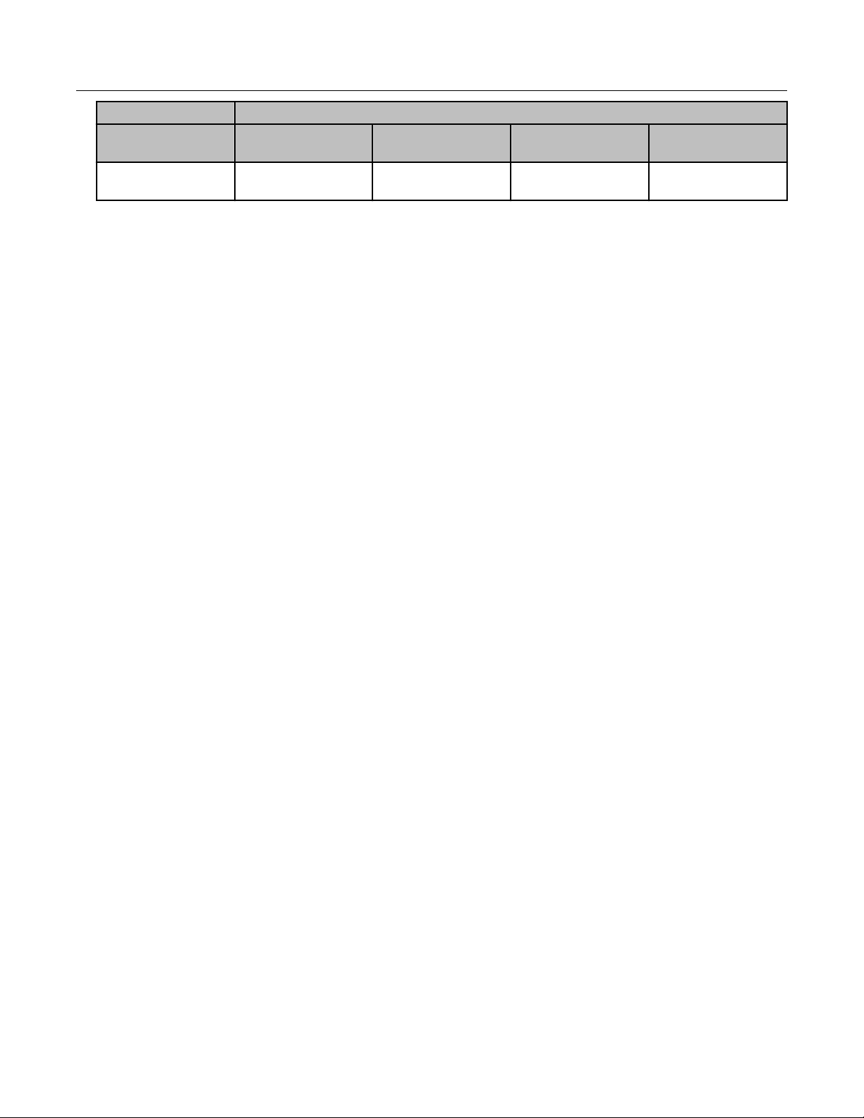
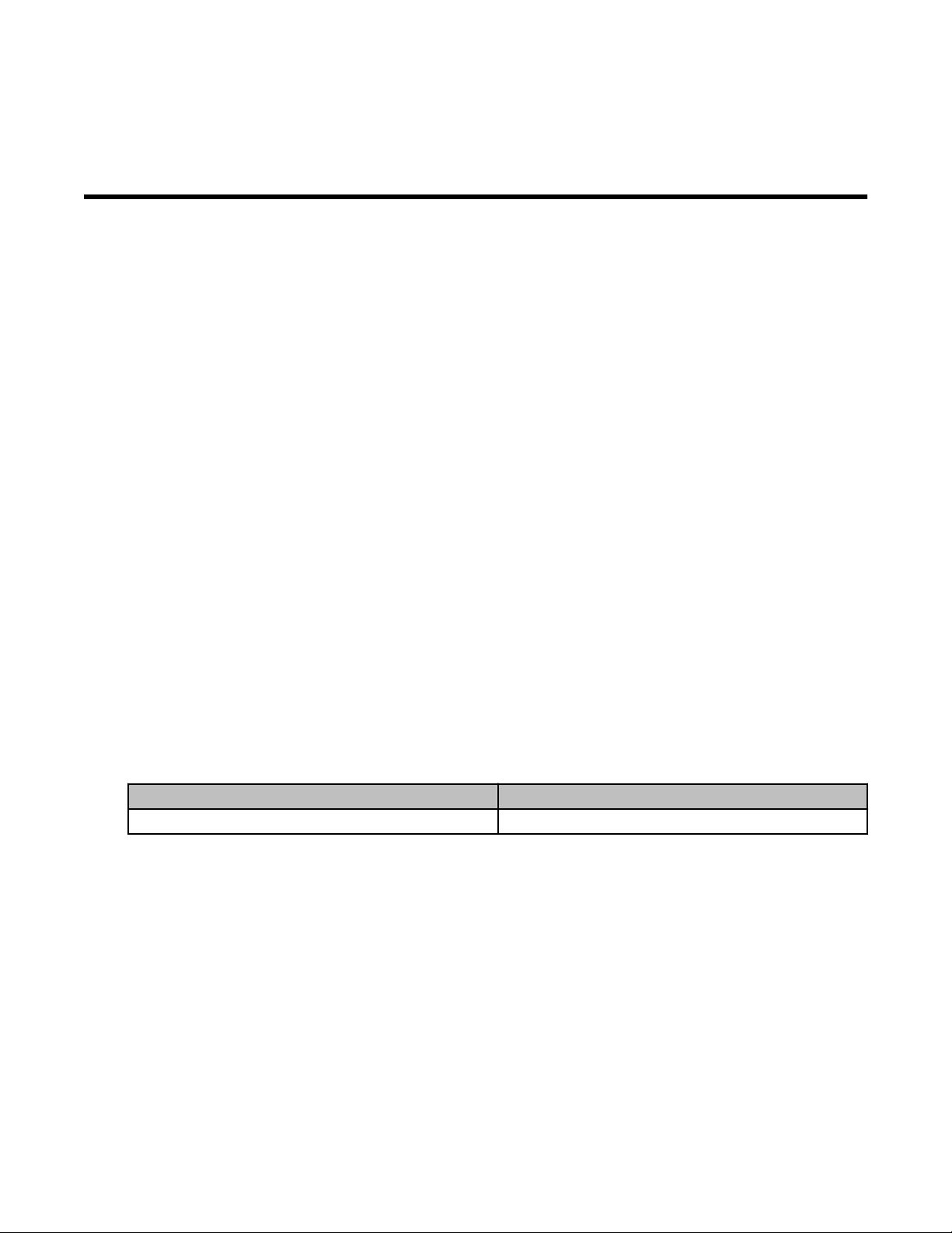
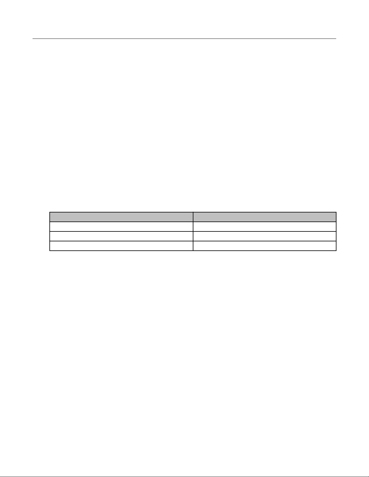
915 MHz Antenna Specifications
This following table provides the specifications for the supported 915 MHz antennas. The
CAM3 is designed to operate with the antennas listed here. Antennas not listed here are
strictly prohibited for use with the ERT Gateway. The required antenna impedance is 50Ω.
Specification 915 MHz Antenna
Itron part number KIT-0049-001 KIT-0073-001 KIT-0018-007 Cisco ANT-MP2-I-
OUT-M
Frequency range
Maximum gain 5.15 dBi 5.5 dBi 8.15 dBi 2.8 dBi
Horizontal
beamwidth
Impedance 50 ohms 50 ohms 50 ohms 50 ohms
Termination Type N Male Type N Male Type N Male MCX jack
Overall length 18.8" 18.8" 65" 3.04”
Radome diameter 1" OD 1" OD 1.31" OD 1.61" OD
Power rating 50W 50W 100W 10W
Lightning
protection
Mounting arm
length
Weight (w/o
clamps)
Maximum wind
speed
902-928 MHz 902–928 MHz 902–928 MHz 698–960 MHz
Omnidirectional Omnidirectional Omnidirectional Omnidirectional
Direct ground Direct ground Direct ground n/a
n/a n/a ~8 in. Direct mounted
1 lb. 0.7 lbs. 3 lbs. 0.2 lbs.
160 mph 160 mph 125 mph 165 mph
OpenWay® Riva CAM3 Installation Guide 7
Proprietary and Confidential
Page 12
Installation Kits
Specification 915 MHz Antenna
Itron part number KIT-0049-001 KIT-0073-001 KIT-0018-007 Cisco ANT-MP2-I-
OUT-M
Wind load @ rated
wind speed
n/a n/a 57 lbs. n/a
Note: To reduce potential radio interference to other users, select an antenna type with gain
such that the equivalent isotropically radiated power (EIRP) is not more than permitted for
successful communication.
OpenWay® Riva CAM3 Installation Guide 8
Proprietary and Confidential
Page 13
Chapter 3 CAM3 Installation for RF-Only
Applications
The following procedures apply to CAM3 installations for RF mesh applications only.
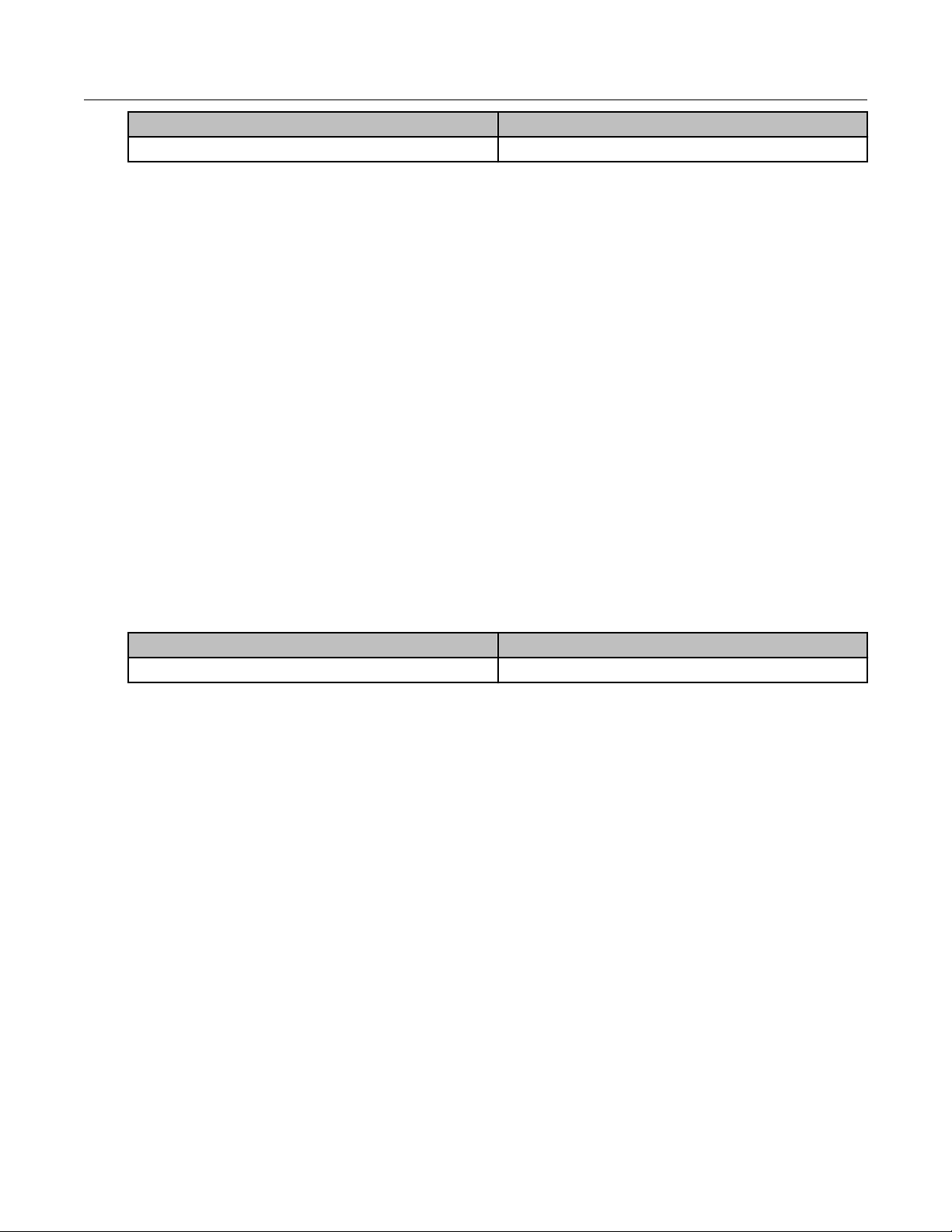
Disconnecting CGR Power
1. Disable the power at the circuit or power supply to which the router AC power cable is
connected.
2. Disconnect the router AC power cable from the AC power connector on the base of the
router enclosure.
Callout Number Description
1 CGR power cable
3. Loosen the six captive bolts that secure the hinged CGR door using the sequence shown
below and swing the door fully open.
OpenWay® Riva CAM3 Installation Guide 9
Proprietary and Confidential
Page 14

CAM3 Installation for RF-Only Applications
Note: The CGR door features an environmental seal that protects the unit against
environmental elements when the door is closed. This seal creates pressure, which can
cause the door to open suddenly when the last bolt is loosened.
The chassis hardware features a pressure-sensitive alarm switch that detects the
opening and closing of the router door and alerts the CGNMS/FND operator to a potential
security breach. When the switch detects that the door has been opened or closed, it
sends an event message to the router, which is stored in the router log file.
Disable the Backup-Battery Unit (BBU) by disconnecting the BBU Harness Cable.
4.
OpenWay® Riva CAM3 Installation Guide 10
Proprietary and Confidential
Page 15
CAM3 Installation for RF-Only Applications
Callout Number Description
1 Backup-Battery Connector
Note: For routers using Cisco IOS, you must disable the BBU by using the IOS CLI and
then disconnecting the BBU harness cable. You can only disable the BBU by terminal or
console access on routers using Cisco CG-OS.
5. Check the SYS LED. To confirm that the router is powered off, verify that the SYS LED is
off. The SYS LED is on the bottom exterior of the router enclosure.
Callout Number Description
1 System LED
OpenWay® Riva CAM3 Installation Guide 11
Proprietary and Confidential
Page 16
CAM3 Installation for RF-Only Applications
Installing the CAM3 for RF-Only Applications
Callout Number Description
1 Slot #5 identifier label
2 CAM3
3 CAM3 retaining screws
1. Locate slot #5 by the slot identifier label inside the CGR.
2. Loosen the two captive screws on the blank cover over slot #5 and remove the cover.
Use either a #2 Phillips or a 9/32" flat-blade screwdriver.
3. Insert the CAM3 into slot #5 of the CGR. Ensure that the CAM3 is oriented so that the
connectors on the rear of the CAM3 are aligned with those in the slot #5. Gently press
the CAM3 until its card-edge connector is firmly seated into the connector in the CGR.
4. Tighten the retaining screws on the front of the CAM3, securing the module in place. Use
either a #2 Phillips or a 9/32" flat-blade screwdriver.
OpenWay® Riva CAM3 Installation Guide 12
Proprietary and Confidential
Page 17
CAM3 Installation for RF-Only Applications
Callout Number Description
1 Antenna cable connection
2 WPAN antenna
3 External antenna connector
5. Secure the black antenna wire from the appropriate antenna to the bottom antenna
connector on the front of the CAM3.
Note: The CGR is shipped with two antenna connection options: the WP
AN antenna and
an external mounted antenna. Internal antenna cables are provided for both options. You
must select the internal antenna cable that connects to the antenna (WPAN or external
remote mounted) being used for this installation and connect it to the antenna connection
on the CAM3.
Ensure that the antenna cable is routed so that it does not interfere with door closure.
6.
Use a single plastic cable tie to secure the antenna cable to the tie loop on the front of
the CAM3.
7. Close the door and secure it by tightening the six captive bolts using the sequence shown
below. Use a torque of 6–7 foot-pounds when tightening the bolts.
OpenWay® Riva CAM3 Installation Guide 13
Proprietary and Confidential
Page 18

CAM3 Installation for RF-Only Applications
8. Affix the regulatory label (included in the CAM3 installation kit) to the door of the CGR, as
shown in the following image.
OpenWay® Riva CAM3 Installation Guide 14
Proprietary and Confidential
Page 19

Chapter 4 ACTD Application Installation
This procedure assumes that the CGR is properly installed and configured. The ACTD
application serves as a communication gateway between the CGR and the IOS and the
CAM3. This procedure also assumes that the user has a basic understanding of networking
such as setup and use of SCP servers and how to find IP addresses.
For further information about setting up the CGR refer to Cisco CGR1000 IOx Application
Development Cook Book .
1. Log on to the CGR.
2. Enable GOS within CGR.
#Enable access to GOS
conf t
line 1/4
transport input all
end
copy r s
3. Log on to the GOS via the console using the same IP address that you use to create an
SSH connection to the IOS. Telnet into port 2070 to access the GOS.
Note: At this point you will have two sessions open: one from the IOS and one from the
GOS.
4. Get hostname, IPv4, and IPv6 addresses from the IOS session.
(OK)
OW2-FAR### show iox host list
Host Name IPV4 Address IPV6 Address
IOX Client Version
----------------------------------------------<gos-hostname>,<gos-ipv4>,gos-ipv6>
0.1
-----------------------------------------------
5. Enable the SSH on the GOS from the IOS.
OW2-FAR### IOX host exec enablessh <gos-hostname>
6. Reset the password.
iox host exec "resetpw itron" OW2-FAR###-GOS-1
7. Set up an SCP server on the same network as the CGR.
8. Ensure that your computer has access to the SCP server.
9. Get the current IPv4 address.
10. Ping your IP address to ensure network connectivity.
OW2-FAR### ping <IPv4 address>
11. Transfer the ACTD image to CGR flash.
OpenWay® Riva CAM3 Installation Guide 15
Proprietary and Confidential
Page 20

ACTD Application Installation
copy flash:<filename> scp://root@<GOS-IPv4>//software/downloads/
<filename>
12. Get the IPv4 address of the GOS.
show iox host list
Transfer the ACTD image from flash to the GOS.
13.
copy flash: <filename>
OW2-FAR### scp://<root ip address>/<pathname>/<gos-hostname> flash:
14. Install ACTD.
iox application install <filename> <ipv6 address>
15. Start ACTD.
OW2-FAR### iox application start actd
16. Verify that the application is running.
show iox application list
OpenWay® Riva CAM3 Installation Guide 16
Proprietary and Confidential
Page 21

Chapter 5 External Antenna Installation
An external antenna is required to ensure optimal radio performance when the CGR is
deployed in a Star configuration for battery powered device (BPD) deployments. Standard
height external antennas are mounted directly above the CGR (3–5 feet above the CGR).
External antennas can be mounted at an extended height above the CGR.
This chapter describes two processes for external antenna installation:
• External Antenna Only
• External Antenna with RF Filter
Note: The requirement for the RF Filter is dependent on the geographic territory where the
CGR is installed and used. The RF Filter is not required for North American deployments.
External Antenna Only
This section describes the installation of an external antenna in territories where an RF Filter
is not required.
Placement
Antenna placement is one of the most important factors in determining overall system
performance. Careful consideration must be given to proper antenna placement. Follow
these general guidelines when determining the ideal location for a remote-mounted external
antenna:
• Mount the antenna vertically.
• Mount the antenna in a location where there is a clear, unobstructed, 360-degree view of
the horizon. The antenna receives and transmits in all directions. Objects such as
building walls, nearby metal surfaces, or other obstructions might interfere with the proper
operation of the antenna.
• Do not mount the antenna on a rooftop where nearby buildings are higher than the
installation location.
• Do not mount the antenna near existing RF radiating antennas. If existing RF radiators
are nearby, the horizontal separation distance must be a minimum of 30 meters and/or
three meters of vertical separation. In instances where nearby RF radiators are present,
conduct an inter-modulation interference study to evaluate the potential for interference
and any effects it may have on system performance. Consult your Itron systems engineer
for more information.
• Height is preferred for optimal performance. Itron recommends installing the antenna no
higher than 30 meters.
A side arm antenna installation must be done if the antenna is mounted where it does not
have an unobstructed 360-degree view. Refer to the following guidelines for a side arm
antenna installation:
OpenWay® Riva CAM3 Installation Guide 17
Proprietary and Confidential
Page 22

External Antenna Installation
• The minimum standoff distance is 60 centimeters, where the interfering structural
members are 10 centimeters or less in diameter and spaced more than two meters apart.
• For structural members between 10 and 25 centimeters in diameter, use a sliding scale of
0.6 to 1.5 meters (for example, a 60-centimeter standoff at 10-centimeter diameter to a
150-centimeter standoff at 25-centimeter member diameter).
Disconnecting the CGR Cables
1. Disconnect the power source from the CGR and remove the power cable.
Callout Number Description
1 CGR power cable
2. Check the SYS LED. To confirm that the router is powered off, verify that the SYS LED is
off. The SYS LED is on the bottom exterior of the router enclosure. If the SYS LED is still
on, the BBU must be disconnected after the CGR door is opened.
OpenWay® Riva CAM3 Installation Guide 18
Proprietary and Confidential
Page 23

External Antenna Installation
Callout Number Description
1 System LED
3. Loosen the six captive bolts that secure the hinged CGR door using the sequence shown
below and swing the door fully open.
Note: The CGR door features an environmental seal that protects the unit against
environmental elements when the door is closed. This seal creates pressure, which can
cause the door to open suddenly when the last bolt is loosened.
The chassis hardware features a pressure-sensitive alarm switch that detects the
opening and closing of the router door and alerts the CGNMS/FND operator to a potential
security breach. When the switch detects that the door has been opened or closed, it
sends an event message to the router, which is stored in the router log file.
Disable the Backup-Battery Unit (BBU) by disconnecting the BBU Harness Cable.
4.
OpenWay® Riva CAM3 Installation Guide 19
Proprietary and Confidential
Page 24

External Antenna Installation
Callout Number Description
1 Backup-Battery Connector
Note: For routers using Cisco IOS, you must disable the BBU by using the IOS CLI and
then disconnecting the BBU harness cable. You can only disable the BBU by terminal or
console access on routers using Cisco CG-OS.
5. Remove the two screws from the ground lug and disconnect the ground cable from the
CGR.
Callout Number Description
1 Ground lug
2 CGR 6 AWG ground cable
OpenWay® Riva CAM3 Installation Guide 20
Proprietary and Confidential
Page 25

Unmounting the CGR
External Antenna Installation
Callout Number Description
1 Mounting bolt to be loosened
2 Mounting bolts to be completely removed
1. Loosen the top front hex head bolt on each side, but do not completely remove.
2. Remove the two rear and lower front hex head bolts on each side of the CGR mounting
bracket.
Removing the CGR Mounting Bracket
OpenWay® Riva CAM3 Installation Guide 21
Proprietary and Confidential
Page 26

External Antenna Installation
Callout Number Description
1 Hex head mounting bolts
2 Center stud with self-locking hex nut
1. Remove the four hex head bolts and set aside. Longer bolts are required to
accommodate the coupler unit bracket and are provided in the ACT Coupler unit
installation kit.
2. Loosen the center self-locking hex nut to allow the bracket to slide upward and off the
center stud.
Installing the CGR Mounting Bracket
Callout Number Description
1 Alignment slots
2 4 Hex head mounting bolts (8mm x 25mm)
supplied with the installation kit
3 Center stud with self-locking hex nut
1. Insert the four 8mm x 25mm mounting screws supplied with the installation kit into the
threaded holes in the base mounting plate. Do not tighten bolts until all are started.
Note: The four alignment slots in the mounting brackets allow the CGR unit to be rotated
either clockwise or counterclockwise for alignment purposes. Inserting the mounting bolts
as shown allow the unit to rotate counterclockwise. Inserting all four bolts in the holes at
the other end of the slot allows the unit to be rotated clockwise.
2. Adjust the alignment of the CGR to the desired orientation and tighten the four mounting
bolts and the hex nut on the center stud. Use a torque of 6–7 foot-pounds when
tightening the bolts and nut.
OpenWay® Riva CAM3 Installation Guide 22
Proprietary and Confidential
Page 27

External Antenna Installation
Installing the CGR
1. Mount the CGR to the mounting bracket by sliding the mounting bolt in the top front
position on each side of the CGR into the corresponding slot on the mounting bracket.
Callout Number Description
1 Mounting bolt not completely removed
2 Mounting bolts to be completely removed
2. Insert the remaining three bolts on each side of the CGR into their respective places.
Note: Insert all mounting bolts on each side before securing tightly.
3.
Tighten all mounting bolts. Use a torque of 6–7 foot-pounds when tightening the bolts.
OpenWay® Riva CAM3 Installation Guide 23
Proprietary and Confidential
Page 28

External Antenna Installation
Reconnecting the CGR Cables
Callout Number Description
1 Ground Lug
2 CGR 6 AWG ground cable
1. Re-insert the two screws to the ground lug and re-connect the ground cable to the CGR.
Callout Number Description
1 CGR power cable
OpenWay® Riva CAM3 Installation Guide 24
Proprietary and Confidential
Page 29

External Antenna Installation
2. Re-connect the power source to the CGR and connect the power cable.
Callout Number Description
1 Backup-Battery Connector
3. Reconnect the Backup-Battery Unit (BBU) by connecting the BBU Harness Cable.
Note: For routers using Cisco IOS, you must disable the BBU by using the IOS CLI and
then disconnecting the BBU harness cable. Y
ou can only disable the BBU by terminal or
console access on routers using Cisco CG-OS.
OpenWay® Riva CAM3 Installation Guide 25
Proprietary and Confidential
Page 30

External Antenna Installation
4. Check the SYS LED. To confirm that the router is powered on, verify that the SYS LED is
on. The SYS LED is on the bottom exterior of the router enclosure.
Assembling the Antenna
1. Remove the black rubber bumper from the end of the antenna.
2. Slide the silicone seal over the base of the antenna.
3. Screw the antenna base into the top of the remote mount adapter plate.
OpenWay® Riva CAM3 Installation Guide 26
Proprietary and Confidential
Page 31

External Antenna Installation
4. Push the silicone seal down over the top of the remote mount adapter plate.
5. Slide the antenna holder over the silicone seal.
OpenWay® Riva CAM3 Installation Guide 27
Proprietary and Confidential
Page 32

External Antenna Installation
6. Make sure the antenna holder and the adapter plate are flush on all sides. See the
following illustrations.
7. Attach the antenna to the mounting bracket.
a) Push the 1¾-inch bolt through the antenna holder, the remote mount adapter plate,
and the mounting bracket.
b) Place the flat washer on the bolt.
c) Place the split washer on the bolt.
d) Add a drop of anti-seize lubricant to the nut and attach the nut to the bolt.
8. Replace the black rubber bumper on the end of the antenna.
External Antenna with RF Filter
This section describes installing the RF Filter to an existing pole-mounted CGR application
that uses the external antenna option. To install the CGR, refer to the CGR installation
procedure in the Cisco 1240 Connected Grid Router Hardware Installation Guide.
OpenWay® Riva CAM3 Installation Guide 28
Proprietary and Confidential
Page 33

External Antenna Installation
An external antenna is required to ensure optimal radio performance when the CGR is
deployed in a Star configuration for battery powered device (BPD) deployments. Standard
height external antennas are mounted directly above the CGR (3–5 feet above the CGR)
and connected to the RF Filter with an external RF cable. External antennas can be
mounted at an extended height above the CGR. The coax RF cable from the RF Filter to the
antenna will be locally sourced to the required length needed for specific antenna mounting
locations (½" superflex is recommended for runs less than 35 feet).
The following illustration indicates how the external antenna and RF filter are connected to a
CGR.
Placement
Antenna placement is one of the most important factors in determining overall system
performance. Careful consideration must be given to proper antenna placement. Follow
these general guidelines when determining the ideal location for a remote-mounted external
antenna:
• Mount the antenna vertically
• Mount the antenna in a location where there is a clear, unobstructed, 360-degree view of
the horizon. The antenna receives and transmits in all directions. Objects like building
walls, nearby metal surfaces, or other obstructions might interfere with the proper
operation of the antenna.
• Do not mount the antenna on a rooftop where nearby buildings are higher than the
installation location.
• Do not mount the antenna near existing RF radiating antennas. If existing RF radiators
are nearby, the horizontal separation distance to the radiator must be a minimum of 30
meters and/or three meters of vertical separation. In instances where nearby RF radiators
are present, conduct an inter-modulation interference study to evaluate the potential for
OpenWay® Riva CAM3 Installation Guide 29
.
Proprietary and Confidential
Page 34

External Antenna Installation
interference and any effects it may have on system performance. Consult your Itron
systems engineer for more information.
• Height is preferred for optimal performance. Itron recommends installing the antenna no
higher than 30 meters.
Caution: Do not install a 5.5 dBi antenna directly on the CGR/CAM3. Antenna
installation directly on the CGR/CAM3 will compromise mechanical integrity and will
not meet the compliance requirements.
Caution: Do not install an 8.15 dBi antenna directly on the CGR/CAM3. Antenna
installation directly on the CGR/CAM3 will compromise mechanical integrity and will
not meet the compliance requirement for a loss of 3.0 dB between the CAM3 and
the 8.15 dBi antenna.
A side arm antenna installation must be done if the antenna is mounted where it does not
have an unobstructed 360-degree view. Refer to the following guidelines for a side arm
antenna installation:
•
The minimum standoff distance is 60 centimeters, where the interfering structural
members are 10 centimeters or less in diameter and spaced more than two meters apart.
• For structural members between 10 and 25 centimeters in diameter, use a sliding scale of
0.6 to 1.5 meters. (For example, a 60-centimeter standoff at 10-centimeter diameter to a
150-centimeter standoff at 25-centimeter member diameter.)
Disconnecting the CGR Cables
1. Disconnect the power source from the CGR and remove the power cable.
Callout Number Description
1 CGR power cable
OpenWay® Riva CAM3 Installation Guide 30
Proprietary and Confidential
Page 35

External Antenna Installation
2. Check the SYS LED. To confirm that the router is powered off, verify that the SYS LED is
off. The SYS LED is on the bottom exterior of the router enclosure. If the SYS LED is still
on, the BBU must be disconnected after the CGR door is opened.
Callout Number Description
1 System LED
3. Loosen the six captive bolts that secure the hinged CGR door using the sequence shown
below and swing the door fully open.
Note: The CGR door features an environmental seal that protects the unit against
environmental elements when the door is closed. This seal creates pressure, which can
cause the door to open suddenly when the last bolt is loosened.
The chassis hardware features a pressure-sensitive alarm switch that detects the
opening and closing of the router door and alerts the CGNMS/FND operator to a potential
security breach. When the switch detects that the door has been opened or closed, it
sends an event message to the router, which is stored in the router log file.
4.
Disable the Backup-Battery Unit (BBU) by disconnecting the BBU Harness Cable.
OpenWay® Riva CAM3 Installation Guide 31
Proprietary and Confidential
Page 36

External Antenna Installation
Callout Number Description
1 Backup-Battery Connector
Note: For routers using Cisco IOS, you must disable the BBU by using the IOS CLI and
then disconnecting the BBU harness cable. You can only disable the BBU by terminal or
console access on routers using Cisco CG-OS.
5.
Remove the two screws from the ground lug and disconnect the ground cable from the
CGR.
Callout Number Description
1 Ground lug
2 CGR 6 AWG ground cable
OpenWay® Riva CAM3 Installation Guide 32
Proprietary and Confidential
Page 37

Unmounting the CGR
External Antenna Installation
Callout Number Description
1 Mounting bolt to be loosened
2 Mounting bolts to be completely removed
1. Loosen the top front hex head bolt on each side, but do not completely remove.
2. Remove the two rear and lower front hex head bolts on each side of the CGR mounting
bracket.
Removing the CGR Mounting Bracket
OpenWay® Riva CAM3 Installation Guide 33
Proprietary and Confidential
Page 38

External Antenna Installation
Callout Number Description
1 Hex head mounting bolts
2 Center stud with self-locking hex nut
1. Remove the four hex head bolts and set aside. Longer bolts are required to
accommodate the coupler unit bracket and are provided in the ACT Coupler unit
installation kit.
2. Loosen the center self-locking hex nut to allow the bracket to slide upward and off the
center stud.
Installing the RF Filter Mounting Bracket
Callout Number Description
1 Center stud with self-locking hex nut
• Slide the RF filter mounting bracket keyhole slot over the center stud on the pole mount
base plate.
OpenWay® Riva CAM3 Installation Guide 34
Proprietary and Confidential
Page 39

Installing the CGR Mounting Bracket
Callout Number Description
1 Alignment slots
2 4 Hex head mounting bolts (8mm x 25mm)
3 Center stud with self-locking hex nut
External Antenna Installation
supplied with the installation kit
1. Position the RF Filter mounting bracket over the center stud and slide down behind hex
nut.
2. Insert the four 8mm x 25mm mounting screws supplied with the installation kit into the
threaded holes in the base mounting plate. Do not tighten bolts until all are started.
Note
: The four alignment slots in the mounting brackets allow the CGR and the filter unit
to be rotated either clockwise or counterclockwise for alignment purposes. Inserting the
mounting bolts as shown allow the unit to rotate counterclockwise. Inserting all four bolts
in the holes at the other end of the slot allows the unit to be rotated clockwise.
3. Adjust the alignment of the CGR and RF Filter to the desired orientation and tighten the
four mounting bolts and the hex nut on the center stud. Use a torque of 6–7 foot-pounds
when tightening the bolts and nut.
OpenWay® Riva CAM3 Installation Guide 35
Proprietary and Confidential
Page 40

External Antenna Installation
Installing the CGR
1. Mount the CGR to the mounting bracket by sliding the mounting bolt in the top front
position on each side of the CGR into the corresponding slot on the mounting bracket.
Callout Number Description
1 Mounting bolt not completely removed
2 Mounting bolts to be completely removed
2. Insert the remaining three bolts on each side of the CGR into their respective places.
Note: Insert all mounting bolts on each side before securing tightly.
3.
Tighten all mounting bolts. Use a torque of 6–7 foot-pounds when tightening the bolts.
OpenWay® Riva CAM3 Installation Guide 36
Proprietary and Confidential
Page 41

Connecting the RF Filter Cables
Callout Number Description
1 Pre-installed N connector
2 CGR to RF Filter cable
External Antenna Installation
1. Connect the CGR-RF Filter cable to the pre-installed N connector on the bottom of the
CGR.
Callout Number Description
1 CGR to RF Filter cable
2. Connect the CGR-RF Filter cable to the pre-installed N connector on the bottom of the
RF Filter.
OpenWay® Riva CAM3 Installation Guide 37
Proprietary and Confidential
Page 42

External Antenna Installation
Reconnecting the CGR Cables
Callout Number Description
1 Ground Lug
2 CGR 6 AWG ground cable
1. Re-insert the two screws to the ground lug and re-connect the ground cable to the CGR.
Callout Number Description
1 CGR power cable
OpenWay® Riva CAM3 Installation Guide 38
Proprietary and Confidential
Page 43

External Antenna Installation
2. Re-connect the power source to the CGR and connect the power cable.
Callout Number Description
1 Backup-Battery Connector
3. Reconnect the Backup-Battery Unit (BBU) by connecting the BBU Harness Cable.
Note: For routers using Cisco IOS, you must disable the BBU by using the IOS CLI and
then disconnecting the BBU harness cable. Y
ou can only disable the BBU by terminal or
console access on routers using Cisco CG-OS.
OpenWay® Riva CAM3 Installation Guide 39
Proprietary and Confidential
Page 44

External Antenna Installation
4. Check the SYS LED. To confirm that the router is powered on, verify that the SYS LED is
on. The SYS LED is on the bottom exterior of the router enclosure.
Assembling the Antenna
1. Remove the black rubber bumper from the end of the antenna.
2. Slide the silicone seal over the base of the antenna.
3. Screw the antenna base into the top of the remote mount adapter plate.
OpenWay® Riva CAM3 Installation Guide 40
Proprietary and Confidential
Page 45

External Antenna Installation
4. Push the silicone seal down over the top of the remote mount adapter plate.
5. Slide the antenna holder over the silicone seal.
OpenWay® Riva CAM3 Installation Guide 41
Proprietary and Confidential
Page 46

External Antenna Installation
6. Make sure the antenna holder and the adapter plate are flush on all sides. See the
following illustrations.
7. Attach the antenna to the mounting bracket.
a) Push the 1¾-inch bolt through the antenna holder, the remote mount adapter plate,
and the mounting bracket.
b) Place the flat washer on the bolt.
c) Place the split washer on the bolt.
d) Add a drop of anti-seize lubricant to the nut and attach the nut to the bolt.
8. Replace the black rubber bumper on the end of the antenna.
Lightning Arrestor
When using an external remote antenna, install a lightning arrestor to protect the equipment
in the event of a lightning strike. The lightning arrestor is fitted between the coaxial antenna
cable and the CGR (or the RF Filter, if applicable). The protected end of the arrestor
OpenWay® Riva CAM3 Installation Guide 42
Proprietary and Confidential
Page 47

External Antenna Installation
connects to the N-connector on the CGR (or RF Filter). The surge end of the arrestor is
connected to the antenna cable. The arrestor is also furnished with a ground lug.
Caution: The lightning arrestor must be connected to an earth-ground.
Weatherproofing the RF Connections
1. W
rap vinyl electrical tape around the connection, starting at the filter and moving up the
cable as shown in the following illustration.
The vinyl electrical tape provides a foundation for the butyl rubber sealant, making it
easier to disconnect the cable.
OpenWay® Riva CAM3 Installation Guide 43
Proprietary and Confidential
Page 48

External Antenna Installation
2. Wrap the vinyl electrical tape up the coaxial cable, overlapping each wrap as shown in
the following illustration.
3. Ensure that the tape fully covers the cable strain relief.
4. W
rap a layer of butyl rubber sealant over the vinyl electrical tape.
5. Ensure that the butyl rubber extends past the vinyl electrical tape and onto the cable
jacket.
6. Overlap the butyl rubber so that no gap exists. The butyl rubber will self-vulcanize over
time and the seam will disappear
.
7. Wrap vinyl electrical tape around the butyl rubber, starting at the filter and moving up as
you did in step 1.
OpenWay® Riva CAM3 Installation Guide 44
Proprietary and Confidential
Page 49

External Antenna Installation
8. Continue wrapping the vinyl electrical tape in a spiral back down to the filter. You should
now have two layers of vinyl electrical tape covering the butyl rubber
.
OpenWay® Riva CAM3 Installation Guide 45
Proprietary and Confidential
Page 50

Chapter 6 Field Replacement
This chapter covers the procedures necessary for successfully replacing an existing CAM
module with a new CAM3 module:
• Using PuTTY to access the CGR console command line
• Identifying the current CAM slot location and status
• Powering down the CAM
• Removing the CAM
• Installing the new CAM3
• Powering up the new CAM3
• Checking the new CAM3 status
• Saving the current CGR CAM configuration
Important: In some geographic territories, such as North America (NAM), the RF Filter is
not needed with a CAM3 module and may be removed if it is already installed for an earlier
CAM module. In this case, the external antenna can be installed without the filter, but it
should NOT be connected directly to the CGR.
Requirements
The following items are required for successful CAM3 field replacement as described in this
chapter:
• ½-inch (13-mm) socket wrench to loosen the router chassis door bolts
• Laptop with USB port running PuTTY or similar terminal application
Note: Go to the PuTTY website to download the latest version of the application: https://
www.putty.org/.
• Credentials for CGR access
• New CAM3
Note: The CAM3 ships in an anti-static shipping bag. Do not remove the CAM3 from the
anti-static shipping bag until it is ready to be placed into the CGR. Save the anti-static
shipping bag for the removed CAM.
• Available CGNMS/FND operator (utility office or Itron Managed Services) to verify CAM3
operation
• CGR communications port access
• Cisco DB9–RJ45 serial cable and USB-to-serial adapter cable
Uninstalling the Existing CAM
This section covers the procedures necessary uninstalling and removing an existing CAM
module prior to installing a new CAM3 module.
OpenWay® Riva CAM3 Installation Guide 46
Proprietary and Confidential
Page 51

Field Replacement
Opening the CGR
Use a ½-inch (13-mm) socket wrench to loosen all six captive bolts that secure the hinged
CGR door using the sequence shown below. Use a torque of 3–4 foot-pounds when
loosening the bolts. The captive bolts cannot be removed from the door.
Note: The CGR door features an environmental seal that protects the unit against
environmental elements when the door is closed. This seal creates pressure, which can
cause the door to open suddenly when the last bolt is loosened.
Door Sensor
The chassis hardware features a pressure-sensitive alarm switch that detects the opening
and closing of the router door and alerts the CGNMS/FND operator to a potential security
breach. When the switch detects that the door has been opened or closed, it sends an
event message to the router. The event message is stored in the router log file.
OpenWay® Riva CAM3 Installation Guide 47
Proprietary and Confidential
Page 52

Field Replacement
Connecting to the CGR
1. Remove the ½-inch (13mm) console port access plug. The console port access plug (1)
is located on the back of the CGR as shown.
2. Connect the USB to serial adapter to the laptop.
3. Plug the blue Cisco cable end into the CGR's RJ45 port, located behind the ½-inch
(13mm) access plug.
OpenWay® Riva CAM3 Installation Guide 48
Proprietary and Confidential
Page 53

Field Replacement
4. Open Windows Device Manager and locate the Prolific USB to Serial adapter and
assigned com port.
5. Open a new PuTTY session and perform the following steps:
a)
In the
Serial line field, enter the comm port (for example, COM22).
b) Set the port Speed to 9600.
c) For Connection type, select Serial.
d) Click Open.
OpenWay® Riva CAM3 Installation Guide 49
Proprietary and Confidential
Page 54

Field Replacement
Confirming the CAM Slot Location
After PuTTY connects to the CGR, a console terminal appears. If you don't see a terminal
prompt, press Enter until the terminal prompt appears. If you still do not get a prompt, exit
PuTTY and switch to a new baud rate. Make sure that the cable is attached and
undamaged.
Note: In the example described here, the CAM is located in Slot #4. If your CAM is located
in Slot #5, the same procedure applies. In this case, use Slot #5.
1. Type enable at the prompt.
ype the console password and press Enter.
2. T
OpenWay® Riva CAM3 Installation Guide 50
Proprietary and Confidential
Page 55

Field Replacement
Note: The password for every CGR is different. The password does not appear on the
screen as you enter it.
3. Type show module.
4. Confirm that the Itron CAM module location is shown (for example, CGR1000 Third
Party Module). In the example above, Mod 4 is Slot #4. Under Status, ok indicates
that the device is powered and active.
Powering Down the CAM
Note: In the example described here, the CAM is located in Slot #4. If your CAM is located
in Slot #5, the same procedure applies. In this case, use Slot #5.
1. Type conf t (configuration terminal). The prompt changes to (config).
T
ype hw power 4 (in this example, the CAM is located in Slot #4).
2.
3. Type do show module.
4. If successful, the Status indicates powered-dn (powered down).
Note:
• If it is not showing powered down, verify that (config) shows in the prompt. If not,
re-enter conf t.
• Once (config) is shown in the prompt, issue the hw power 4 command a second
time.
• Verify that the Status is powered-dn with another do show module command.
Verifying the CAM Location
After the CAM is powered down, use the following procedure to check the hardware
components.
Note: In the example described here, the CAM is located in Slot #4. If your CAM is located
in Slot #5, the same procedure applies. In this case, use Slot #5.
OpenWay® Riva CAM3 Installation Guide 51
Proprietary and Confidential
Page 56

Field Replacement
1. Locate the slot used for the CAM as found using PuTTY above.
2. Verify the slot is occupied by the Itron CAM. Visual identification cues are as follows:
1. Has two small coaxial connectors labeled A1 and A2.
Note: only one coaxial connector (A1) is used in North America.
2. Has a PLC port labeled P3.
3. Has a mini USB connector next to A1.
Removing the CAM
Note: In the example described here, the CAM is located in Slot #4. If your CAM is located
in Slot #5, the same procedure applies. In this case, use Slot #5.
Once visually verified, the CAM may be removed from the CGR chassis.
OpenWay® Riva CAM3 Installation Guide 52
Proprietary and Confidential
Page 57

Field Replacement
1. Remove the new CAM3 from its anti-static bag and place the old CAM in the anti-static
bag.
2. Remove the coaxial cable from port A1.
3. Remove the two Phillips screws securing the CAM module to the CGR chassis.
4. Pull up and out on the module handles to slide the module out of the CGR chassis on
mounting rails.
Installing the New CAM3
1. Insert the new CAM3 into the same slot that the old CAM was removed from. Lightly push
down on the CAM3 module's handles. Y
place for it to fully seat.
Caution: Do not force the CAM3 module into place.
Replace the two Phillips screws, securing the CAM3 module to the CGR chassis.
2.
3. Replace the coaxial cable onto port A1.
Powering Up the CAM3
The CGR will automatically log out the user after 10–15 minutes of inactivity. While
replacing the CAM, the CGR may have automatically logged you out. Log back on to the
CGR and return to the (config) user prompt, as described in Confirming the CAM Slot
Location on page 50.
Note: In the example described here, the CAM is located in Slot #4. If your CAM is located
in Slot #5, the same procedure applies. In this case, use Slot #5.
ou may need to vertically rock the module into
OpenWay® Riva CAM3 Installation Guide 53
Proprietary and Confidential
Page 58

Field Replacement
1. At the config prompt, enter hw-module poweroff 4 (for Slot #4).
Note: If the CAM3 is located in Slot #5, enter hw-module poweroff 5.
2. At the config prompt, enter do show module.
3. Verify that the new Status indicates powered-dn.
Confirming the CAM3 Status
1. At the config prompt, enter no hw-module poweroff 4 (for Slot #4).
Note: If the CAM3 is located in Slot #5, enter no hw-module poweroff 5.
2. At the
3. Verify that the new Status indicates ok.
config prompt, enter do show module.
OpenWay® Riva CAM3 Installation Guide 54
Proprietary and Confidential
Page 59

Ending the CGR PuTTY Connection
1. At the config prompt, enter end to return to the original command prompt.
2. Enter copy r s at the prompt.
Field Replacement
3. When prompted for Destination filename [startup-config], press Enter.
4. Type exit at the prompt.
5. Call your local FND/CGNMS operator to confirm CAM3 operation. When operation is
confirmed, you can unplug the console cable.
Closing the CGR
1. Replace the ½-inch (13mm) console port plug.
2. Close the door and secure it by tightening the six captive bolts using the sequence shown
below. Use a torque of 6–7 foot-pounds when tightening the bolts.
OpenWay® Riva CAM3 Installation Guide 55
Proprietary and Confidential
 Loading...