

Page 1

Bridges Hardware Guide
Silver Spring Networks
555 Broadway Street
Redwood City, CA 94063
www.silverspringnet.com
Page 2

Bridges Hardware Guide
Bridges Hardware Guide
Document Number BRIDGESv2.0UG_Rev1
Confidential Information of Silver Spring Networks®, Inc., provided to licensed customer under NDA.
Copyright © 2010, Silver Spring Networks, Inc. All rights reserved.
The Silver Spring Networks logo, UtilityIQ®, and UtilOS® are registered trademarks of Silver Spring Networks, Inc.
Smart Energy Networks™, Success.Guaranteed™, Metro Gateway™, Metro Relay™, Gas Interface Management
Unit™, and Water Interface Management Unit™ are trademarks of Silver Spring Networks, Inc.
All other company and product names are used for identification purposes only and may be registered trademarks,
trademarks, or service marks of their respective owners.
Please consider the environment before printing this document.
Revision
number Date Revision
1 June 16, 2010 Add FCC 15.247 information to Appendix, and incorporate updates to specify
max gain for sBridge and eBridge.
Bridges Hardware Guide Silver Spring Networks 2
Page 3

Contents
Contents
1. Introduction . . . . . . . . . . . . . . . . . . . . . . . . . . . . . . . . . . . . . . . . . . . . . . . . . . . . . . . . . . . . . . 4
The eBridge . . . . . . . . . . . . . . . . . . . . . . . . . . . . . . . . . . . . . . . . . . . . . . . . . . . . . . . . . . . . . . . . . . . . . 4
The sBridge . . . . . . . . . . . . . . . . . . . . . . . . . . . . . . . . . . . . . . . . . . . . . . . . . . . . . . . . . . . . . . . . . . . . . 5
Audience. . . . . . . . . . . . . . . . . . . . . . . . . . . . . . . . . . . . . . . . . . . . . . . . . . . . . . . . . . . . . . . . . . . . . . . . 6
Silver Spring Networks Documentation . . . . . . . . . . . . . . . . . . . . . . . . . . . . . . . . . . . . . . . . . . . . . . . . 6
Customer Support . . . . . . . . . . . . . . . . . . . . . . . . . . . . . . . . . . . . . . . . . . . . . . . . . . . . . . . . . . . . . . . . 7
2. Deploying Silver Spring Networks Bridges . . . . . . . . . . . . . . . . . . . . . . . . . . . . . . . . . . . . 8
Installing Bridges in the Network . . . . . . . . . . . . . . . . . . . . . . . . . . . . . . . . . . . . . . . . . . . . . . . . . . . . . 8
Types of Bridge Deployments . . . . . . . . . . . . . . . . . . . . . . . . . . . . . . . . . . . . . . . . . . . . . . . . . . . . . . . 9
Deployment Considerations . . . . . . . . . . . . . . . . . . . . . . . . . . . . . . . . . . . . . . . . . . . . . . . . . . . . . . 10
Supported Network Topologies . . . . . . . . . . . . . . . . . . . . . . . . . . . . . . . . . . . . . . . . . . . . . . . . . . . . 11
Master/Remote Topology . . . . . . . . . . . . . . . . . . . . . . . . . . . . . . . . . . . . . . . . . . . . . . . . . . . . . . . . 11
Centralized and Decentralized Master/Remote Deployments . . . . . . . . . . . . . . . . . . . . . . . . . . . . 12
Teaming Topology . . . . . . . . . . . . . . . . . . . . . . . . . . . . . . . . . . . . . . . . . . . . . . . . . . . . . . . . . . . . . 13
Supported Interfaces . . . . . . . . . . . . . . . . . . . . . . . . . . . . . . . . . . . . . . . . . . . . . . . . . . . . . . . . . . . . . 13
Ethernet . . . . . . . . . . . . . . . . . . . . . . . . . . . . . . . . . . . . . . . . . . . . . . . . . . . . . . . . . . . . . . . . . . . . . 13
Serial . . . . . . . . . . . . . . . . . . . . . . . . . . . . . . . . . . . . . . . . . . . . . . . . . . . . . . . . . . . . . . . . . . . . . . . . 14
Deployment Mode Examples . . . . . . . . . . . . . . . . . . . . . . . . . . . . . . . . . . . . . . . . . . . . . . . . . . . . . . . 14
Mixed IPv4 Sample Deployment (Master eBridge only) . . . . . . . . . . . . . . . . . . . . . . . . . . . . . . . . . 14
Serial Master/Serial Remote IPv6 Sample Deployment . . . . . . . . . . . . . . . . . . . . . . . . . . . . . . . . . 15
IPv6 Addressing in the RF Network . . . . . . . . . . . . . . . . . . . . . . . . . . . . . . . . . . . . . . . . . . . . . . . . 16
Ethernet Teaming Sample Deployment . . . . . . . . . . . . . . . . . . . . . . . . . . . . . . . . . . . . . . . . . . . . . 16
A. Specifications . . . . . . . . . . . . . . . . . . . . . . . . . . . . . . . . . . . . . . . . . . . . . . . . . . . . . . . . . . 18
Overview. . . . . . . . . . . . . . . . . . . . . . . . . . . . . . . . . . . . . . . . . . . . . . . . . . . . . . . . . . . . . . . . . . . . . . . 18
eBridge and sBridge Features . . . . . . . . . . . . . . . . . . . . . . . . . . . . . . . . . . . . . . . . . . . . . . . . . . . . . . 18
Silver Spring Networks eBridge Specifications. . . . . . . . . . . . . . . . . . . . . . . . . . . . . . . . . . . . . . . . . . 19
Silver Spring Networks sBridge Specifications. . . . . . . . . . . . . . . . . . . . . . . . . . . . . . . . . . . . . . . . . . 22
Regulatory Compliance - Module Certifications . . . . . . . . . . . . . . . . . . . . . . . . . . . . . . . . . . . . . . . . . 24
FCC Certification (Radiated/Conducted Emissions Compliance FCC Part 15.247) . . . . . . . . . . . . 24
Industry Canada Certification (Radiated/Conducted Emissions Compliance RSS-210) . . . . . . . . . 24
C-Tick Level 3 (Radiated/Conducted Emissions Compliance AS/NZS4268, AS/NZS4778) . . . . . . 25
Silver Spring Networks NIC, FCC IDs:
OWS-NIC515 IC: 5975A-NIC515 (sBridge)
OWS-NIC506, IC:5875A-NIC506 (eBridge) . . . . . . . . . . . . . . . . . . . . . . . . . . . . . . . . . . . . . . . . . . 25
Glossary . . . . . . . . . . . . . . . . . . . . . . . . . . . . . . . . . . . . . . . . . . . . . . . . . . . . . . . . . . . . . . . . . . 27
Index . . . . . . . . . . . . . . . . . . . . . . . . . . . . . . . . . . . . . . . . . . . . . . . . . . . . . . . . . . . . . . . . . . . . . 36
Bridges Hardware Guide Silver Spring Networks 3
Page 4

1 Introduction
1 Introduction
Silver Spring Networks’ Distribution Automation (DA) network is designed to help electrical
utilities manage field devices such as reclosers, capacitor banks, voltage regulators, and
transformers, through more efficient two-way communication. The utilities’ primary tools for
monitoring power distribution systems are called Remote Terminal Units (RTUs).
Utilities use Supervisory Control And Data Acquisition (SCADA) centers to remotely control
substation and distribution equipment through these RTUs. Unfortunately, many RTUs don’t
communicate effectively to SCADA management systems, making fault detection and field
response difficult. The DA network is designed to address this problem, by building a
comprehensive fault-tolerant wireless IP network for two-way communications with distribution
RTUs.
The devices used to improve communications between the utility’s SCADA central office and its
RTUs are the Silver Spring Networks eBridge
are separate bridge types that differ based on their provided types of port connectors.
®
and the Silver Spring Networks sBridge®. Each
Note: In this document, whenever applicable, the eBridge and sBridge will be referred to generically
as “bridges.”
Silver Spring Networks bridges are devices that provide a network for reliable and secure IPbased two-way communications between RTUs and the SCADA system. Faster communication
with RTUs helps create a smarter, more reliable electrical grid.
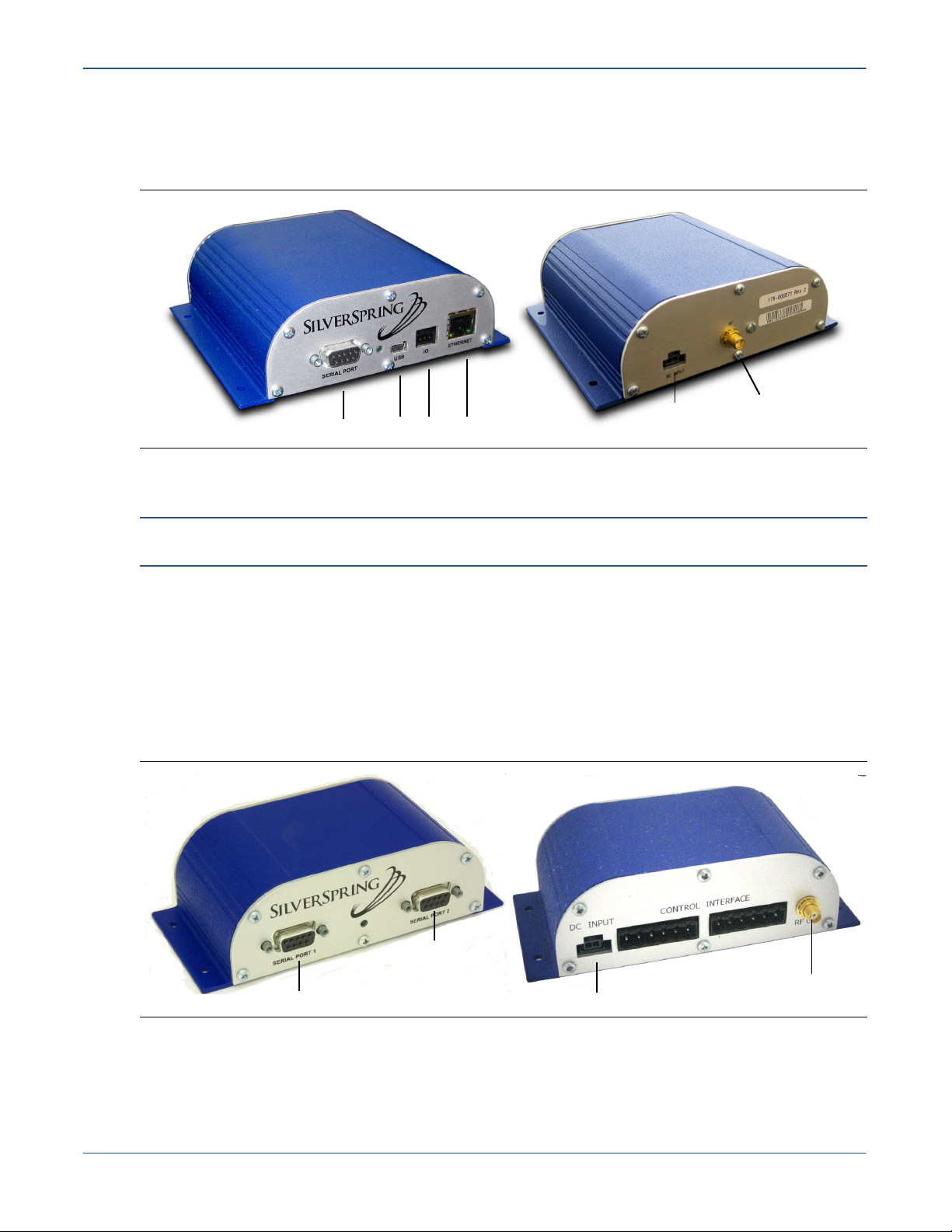
The eBridge
The eBridge provides the following interfaces:
• One (1) 100Base-T RJ-45 Ethernet interface.
• One (1) DB-9 nine-pin serial interface.
• One (1) 900 MHz RF wireless interface.
The Ethernet port on the eBridge often connects to the network leading to the back office or the
electrical substation SCADA system. A remote eBridge can use its Ethernet port to connect to one
Bridges Hardware Guide Silver Spring Networks 4
Page 5
1 Introduction
or more RTUs. The RF interface connects all bridges together in a routable RF wireless network
for DA communications. A serial port can also be used for RTU connections.
Figure 1. Front and back view of the eBridge
The sBridge
Note: sBridges can be used for meter connectivity and for DA RTU connectivity.The application
described in this guide is for DA connectivity. sBridges are not designed for use as a master bridge.
The Silver Spring Networks sBridge provides similar functionality to the eBridge, with the
primary difference being support for two serial interfaces as shown in Figure 2. Serial port 1 is
designated as a remote communication port, passing raw serial traffic, for central offices to
diagnose, monitor and remotely configure the device. Serial port 2 connects to an RTU and
passes DNP3/IP traffic. Either port can be set to function in either mode. As with the eBridge, an
RF interface connects the sBridges to the RF network.
Serial port
Front
USB Ethernet
GPIO
Back
SMA female RF conn.
Power
Figure 2. Front and rear view of the sBridge
Serial Port 2
SMA female RF
Serial Port 1
Bridges Hardware Guide Silver Spring Networks 5
Power
connector
Page 6
1 Introduction
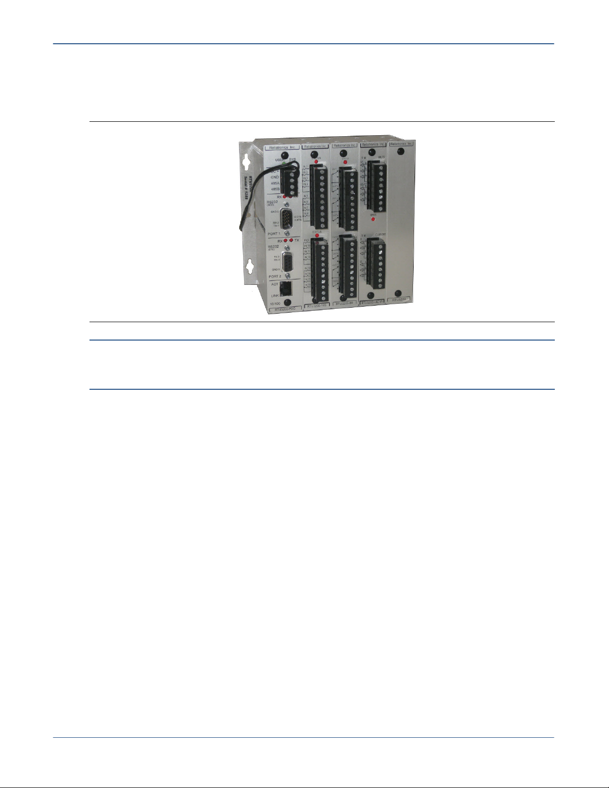
Figure 3 shows an example of an RTU, which provides an Ethernet port, two serial ports and
terminals for the electrical equipment to which it connects.
Figure 3. An RTU
Note: For more information about network deployments of the eBridge and sBridge, refer to Chapter 2,
Deploying Silver Spring Networks Bridges on page 8. For instructions on how to configure eBridges and
sBridges, refer to the Bridge Configurator 2.0 User’s Guide.
Audience
This guide is intended for networking and IT professionals and system administrators who
perform one or more of the following tasks:
• Management of distribution electrical equipment
• Network Management
• Support information technology
• Install, monitor and troubleshoot devices
Silver Spring Networks Documentation
Silver Spring Networks provides the following documents:
• Bridges Hardware Guide (this document)
• Bridge Configurator 2.0 User’s Guide (software for configuring bridges)
• DA NEM 1.0 User’s Guide
Other documents may be available from the Silver Spring Networks web site:
www.silverspringnet.com
Bridges Hardware Guide Silver Spring Networks 6
Page 7

1 Introduction
Customer Support
Silver Spring Networks offers expert technical support and guaranteed response times.
Table 1. Support Information
Country Email Telephone Hours
Australia aus-support@silverspringnet.com +03 9607 8521 9:00 AM - 6:00 PM
Canada support@silverspringnet.com Toll free:
Worldwide +1-650-298-4298
1-888-SSN-9876
(1-888-776-9876)
6:00 AM - 6:00 PM
US Pacific TimeUnited States
Bridges Hardware Guide Silver Spring Networks 7
Page 8

2 Deploying Silver Spring Networks Bridges
2 Deploying Silver Spring Networks
Bridges
Essential to the complete creation of a DA network are the Silver Spring primary devices: the
eBridge and the sBridge. The DA network is designed to help utilities effectively communicate
with field-installed remote terminal units (RTUs) and power system device controllers in the
electrical distribution network.
This chapter introduces the use of Silver Spring Networks eBridges and sBridges to create and
support the Distribution Automation (DA) network, in the following topics:
• Installing Bridges in the Network on page 8
• Deployment Considerations on page 10
• Deployment Mode Examples on page 14
Note: For complete information on configuring and deploying bridges, please see the Bridge
Configurator 2.0 User’s Guide.
Installing Bridges in the Network
Four basic steps are required to install eBridges and sBridges for supporting Distribution
devices:
1. Physical Installation: bridges are not weather-hardened. They must be installed indoors
or inside a weather-hardened enclosure, normally in the same enclosure as the RTU or device
controller. Four mounting holes are located on the bottom edges of the bridge chassis.
2. Bridge Powerup: preferably, along with a battery backup.
3. RF Antenna Attachment: bridges may be connected with different antennas depending on
the application. All antennas connect to the SMA female RF connector on the back of all
bridges. Keep the following considerations in mind when attaching the proper antenna for
the current device:
CAUTION: With the sBridge, using an antenna with greater than 3dBi gain is not
allowed. Up to 6dBi is allowable with the eBridge.
a. The recommended antennas for use in outdoor environments are listed in Table 2, below.
b. An N-Female to SMA-male adapter is required for antenna cable connection to the SMA
connector on the back of the bridge.
c. Because the SMA connector is so small, physical stress may result when connecting a
heavy coaxial transmission cable to the back of the eBridge or sBridge during installation.
Use a pigtail on the SMA connector to support the weight of a heavy transmission line to
the bridge.
Bridges Hardware Guide Silver Spring Networks 8
Page 9
2 Deploying Silver Spring Networks Bridges
4. Interface Connections: Connect the required interface cables between the bridge and the
RTU.
Table 2. Available antennas for Silver Spring Network bridges
SSN Antenna Part # Description
315-00012 Rev. 5 JPole antenna
315-000002 Rev. A sBridge: Rubber Duck, 3dBI maximum gain, SMA Female, Antenna
eBridge: Rubber Duck, 6dBI maximum gain, SMA Female, Antenna
Bridges can also connect to voltage, capacitor, tap changer and VAR management controllers,
which usually provide their own serial and Ethernet ports. The eBridge or sBridge must be
installed in the same enclosure as the controller.
Types of Bridge Deployments
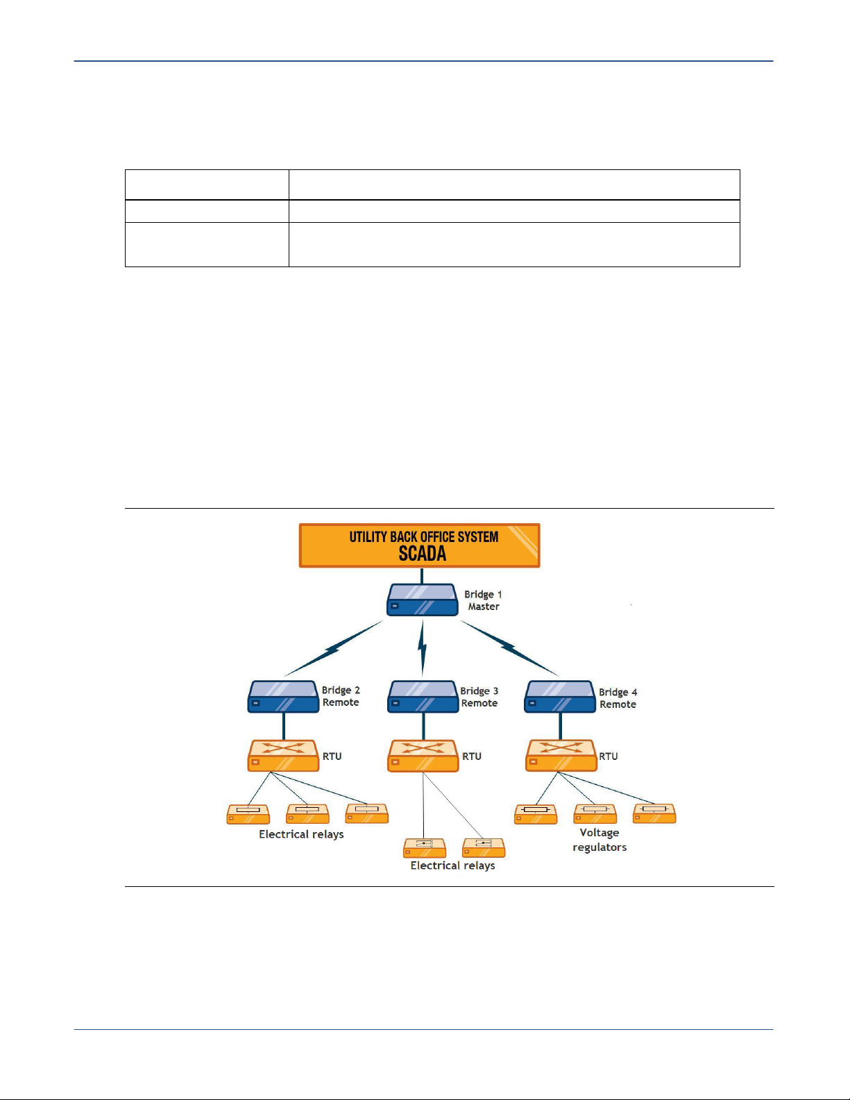
RTUs are key components of the electrical system that act as collection points for sensor data and
issue simple commands to control relays, regulators and other electrical system distribution
devices. After installation, the bridges bring the RTUs into a new Distribution Automation (DA)
network. Figure 4 shows a highly simplified example.
Figure 4. Example of a Master/Remote bridge deployment
Bridges Hardware Guide Silver Spring Networks 9
Page 10

2 Deploying Silver Spring Networks Bridges
Deployment Considerations
Before deploying bridges, allow for the following deployment considerations:
• Network topology
• Interfaces and protocols
• Deployment modes
Table 3 summarizes bridge deployment choices in the network.
Table 3. Bridge Deployment Topologies and Modes
Deployment
Considerations Description
Network topology Bridges can be deployed in the following network topologies:
• Master/Remote (with a centralized Master or decentralized Masters)
• Teaming
• Combination of Master/Remote and Teaming
For more information about DA network topology, refer to Supported Network
Topologies on page 11.
Interfaces and
protocols
Deployment modes The eBridge supports the following deployment modes:
The eBridge supports the following interfaces and protocols:
• Ethernet using IPv4
• Serial using IPv4 or IPv6
For more information on this topic, refer to Supported Interfaces on page 13.
The sBridge supports the following interfaces:
• Serial using IPv4 or IPv6
All bridges operate RF interfaces in a wireless network, running IPv6 by default.
• Mixed IPv4 (Ethernet Master/Serial Remote)
• Mixed IPv6 (Ethernet Master/Serial Remote)
• Ethernet Master/Ethernet Remote
• Ethernet Master/Serial and Ethernet Remotes
• Serial Master/Serial Remote
• Ethernet Teaming and Serial Teaming
The sBridge supports the following deployments:
• Serial Remote
• Serial Teaming
Note: The sBridge operates only as a Remote or in teaming mode. sBridges do not operate as a
Master.
Bridges Hardware Guide Silver Spring Networks 10
Page 11

2 Deploying Silver Spring Networks Bridges
Supported Network Topologies
To accommodate placements of existing RTUs in the field, bridge units can be deployed in the
following network topologies:
• Master/Remote Topology
• Teaming Topology on page 13
• A combination of Master/Remote and Teaming Topology
In the Master/Remote topology, a master bridge connects to the SCADA (Supervisory Control
And Data Acquisition) master. The master bridge communicates over RF to remote bridges that
connect in turn to RTUs.
Master/Remote Topology
In the Master/Remote topology, an eBridge master residing at the substation communicates with
a larger set of remote bridges in the field.
Note: Master and Remote bridges are configured as Masters and Remotes at the manufacturing
facility. The first device to be deployed in the DA network is the master device, which can act as the
takeout point for DA management traffic bound for the CO. The master bridge may also connect to an
Access Point, that itself acts as the takeout point for the DA network. In our examples for this chapter,
an Access Point is not shown.
To deploy bridges in a Master/Remote topology:
• At a substation, connect the master bridge to the local SCADA master.
• In the field, connect an eBridge or sBridge Remote to the RTU.
When the SCADA master sends a message to the RTU, it passes through the master bridge,
which sends it on to the remote bridge in the field, wirelessly via RF. The remote, in turn,
passes the message to the RTU. In an extremely simplified manner, this system represents
Bridges Hardware Guide Silver Spring Networks 11
Page 12

2 Deploying Silver Spring Networks Bridges
the DA (Distribution Automation) network, as indicated in Figure 5. Here, the pre-existing
electrical distribution grid is overlaid with the bridge-based DA network deployment.
Figure 5. Master/Remote Example
Relays are used to extend the RF signal to greater distances and to extend the signal around
obstacles in the field.
Centralized and Decentralized Master/Remote Deployments
A Master/Remote deployment can be centralized or decentralized. In a centralized Master/
Remote deployment, the SCADA system resides at the back office and all data is drawn back to
the central location. This resembles the classic “star” network.
Figure 6. Example of a Centralized Master/Remote Deployment
Bridges Hardware Guide Silver Spring Networks 12
Page 13

2 Deploying Silver Spring Networks Bridges
In a decentralized Master/Remote deployment, multiple SCADA systems exist (for example,
substations in different locations) and data is drawn back to multiple points. Larger DA networks
will roughly follow this model.
Figure 7. Example of a Decentralized Master/Remote Deployment
Teaming Topology
In the Teaming topology, a small set of bridges send each other messages to accomplish specific
tasks. There can be up to ten members in a team and an unlimited number of teams. In Teaming,
bridges communicate with each other, maintaining all routes to all members of the team.
Teaming is useful when dealing with devices such as reclosers that need to communicate with
each other to accomplish group switching and fault isolation. These devices require a Teaming
topology because it supports routing tables to all possible combinations of paths.
Refer to Figure 10 for an illustration of a Teaming topology.
Supported Interfaces
Connect bridges to a SCADA network and/or RTUs through either of the following interfaces:
• Ethernet
• Serial
Ethernet
eBridge only: In Ethernet mode, the eBridge connects to an RTU through an Ethernet
interface. Because all communication between bridges over the Silver Spring Networks RF
network always uses IP, the end point of the network is the RTU. When an eBridge uses Ethernet
to communicate with an RTU, it operates like a router and does not require DNP information.
When a packet comes across the RF network, the bridge makes a routing decision to send the
packet to the destination IP address (an RTU).
On master bridges, Ethernet is used to communicate with the SCADA network.
Bridges Hardware Guide Silver Spring Networks 13
Page 14

2 Deploying Silver Spring Networks Bridges
Serial
In serial mode, the remote or teaming bridge connects to an RTU through a serial interface.
Because serial RTUs have DNP addresses, the end point of the IP network is the bridge device.
Note: The Silver Spring Networks sBridge provides two DB-9 serial interfaces. (The eBridge provides
a single DB-9 serial port.) On the sBridge, one port is dedicated to DNP3 traffic for the RTU (Serial Port
2) and the second serial port (Serial Port 1) passes raw serial traffic regardless of protocol, operating
as a terminal communication port for remote troubleshooting and control. Either port can function with
either setting; use the Bridge Configurator software to configure the ports.
When the remote or teaming bridge receives a packet, it removes the IP header and forwards the
DNP3 payload serially to the RTU device.
During network configuration, a DNP3-to-IP mapping table is created by the Bridge Configurator
software; this mapping table is stored on the master bridge. When the master bridge receives a
DNP3 packet from the SCADA system, it uses that table to look up the destination IP address,
encapsulates the DNP3 packet into an IP header and sends it to the destination bridge, where it is
de-encapsulated back into DNP3 and forwarded over the serial port to the destination RTU.
The RTUs communicate with the master bridge using the master bridge’s IP address. The
eBridge and sBridge support both IPv4 and IPv6 in serial mode.
Deployment Mode Examples
This section provides the following deployment mode examples:
• Mixed IPv4 Sample Deployment (Master eBridge only) below
• Serial Master/Serial Remote IPv6 Sample Deployment on page 15
• Ethernet Teaming Sample Deployment on page 16
Mixed IPv4 Sample Deployment (Master eBridge only)
In Mixed deployments, the master bridge connects to the SCADA master through its Ethernet
interface, while its associated remote bridges connect to RTUs, in this case voltage regulators
shown in Figure 8, through serial ports. The master bridge acts as a router, routing packets
between its Ethernet and RF interfaces, and does not perform DNP encapsulation. The remotes
encapsulate DNP messages coming from the voltage regulators into IP messages, and pass them
on to the master bridge. The remote bridges also de-encapsulate incoming IP messages from the
Bridges Hardware Guide Silver Spring Networks 14
Page 15

2 Deploying Silver Spring Networks Bridges
master bridge into DNP messages, and pass them on to the RTU. The remote bridges require the
DNP address of the RTU to which they are serially connected.
Figure 8. Example of a Mixed IPv4 Deployment
Serial Master/Serial Remote IPv6 Sample Deployment
In Serial Master/Serial Remote deployments, no Ethernet/IP network appears at the master
bridge location. The master connects to the SCADA network using DNP3 over serial. In this case,
the master requires the DNP address from both the SCADA system and from the voltage
regulators. The master bridge performs DNP encapsulation and de-encapsulation from its serial
interface to IP over the RF network. The master requires the DNP3 address of the voltage
regulators because it routes to the remote bridges using IPv6 addresses across the RF network.
Figure 9. Example of a Serial Master/Serial Remote IPv6 Deployment Mode
Bridges Hardware Guide Silver Spring Networks 15
Page 16

2 Deploying Silver Spring Networks Bridges
The Bridge Configurator program provides the settings to associate the DNP3-based RTU
address with each Remote bridge.
IPv6 Addressing in the RF Network
When a device registers with a subnet, the master bridge assigns it an IPv6 prefix, which the
device appends to its MAC address to create a globally unique IPv6 unicast address, formatted
according to the IEEE EUI-64 standard.
All Silver Spring IPv6 network addresses contain the prefix 2001:1868:209::/48 (defined at
the manufacturing facility, this value cannot be changed) with a 16-bit reserved subnet value
(0xfffd) and the MAC address of the device.
For example:
2001:1868:209:fffd::/64+MAC Address
When the master sends a message to one of the RTUs, it contains the IPv6 prefix plus the MAC
address of the eBridge master.
For example, given an original Ethernet MAC address for an eBridge master:
00-0C-F1-56-98-AD
Each Silver Spring Networks bridge provides a sticker on the rear of the case showing the 64-bit
MAC address of the device. This value is the EUI-64 value, containing the inserted 0xfffd value
to extend the original 48-bit MAC to a 64-bit MAC address.
00:0C:F1:FF:FE:56:98:AD
When operating in the RF network in IPv6, the bridge recalculates the MAC to the bridge’s IPv6
unicast address by complementing the high-order byte of the EUI-64 MAC address and
appending it to the prefix.
2001:1868:209:fffd:020C:F1FF:FE56:98AD
When the remote bridge sends a message back to the master eBridge, the message must contain
that same prefix and IPv6 unicast address in its packet header. This value also appears in
diagnostics and logs, in the Bridge Configurator software, as a true IPv6 unicast address.
Note: Each sBridge and eBridge provides the device’s unique IEEE EUI-64 MAC address in a sticker
on the back of the bridge chassis. In this case, the high-order byte is not complemented, remaining as
0x00, as it is the 64-bit MAC hardware address of the device.
Ethernet Teaming Sample Deployment
In Ethernet teaming, a group of bridges send each other messages to accomplish specific tasks
with reclosers. In a traditional DA communications network, all devices communicate with one
or more SCADA masters. Individual DA devices, such as capacitor banks or reclosers, do not
communicate with each other.
However, new types of reclosers can communicate with their neighbor reclosers to effect a
coordinated switching action in the event of an electrical fault. This helps rapidly isolate the
electrical fault and reduce the duration of the electrical outage. For reclosers to communicate
with each other, Teaming mode is required. Teaming mode forces each member of a team to
Bridges Hardware Guide Silver Spring Networks 16
Page 17

2 Deploying Silver Spring Networks Bridges
determine the routing paths to all other members of the team. Figure 10 shows the path of
various messages between the teaming members.
Figure 10. Example of an Ethernet Teaming Deployment Mode
1. The recloser IPx2 sends an
“Open” message to the
recloser at IPy2 through
the predetermined path.
Ethernet
192.168.0.4
192.168.0.5
192.168.0.8
2. Bridge IPx1 sends
the packet to
eBridge IPy1 over RF.
Ethernet
192.168.0.9
3. This bridge receives the
“Open” message from IPx1
and sends it, through Ethernet,
to the recloser at IPy2.
192.168.0.6
Ethernet
192.168.0.7
Substation
All team members exist on the same subnet. An eBridge or Access Point acts as the master for the
teaming network.
Note: For more information on configurations and bridge deployment modes, see the Bridge
Configurator 2.0 User’s Guide.
Bridges Hardware Guide Silver Spring Networks 17
Page 18

A Specifications
A Specifications
Specifications are provided in the following topics:
• Overview
• eBridge and sBridge Features
• Silver Spring Networks eBridge Specifications on page 19
• Silver Spring Networks sBridge Specifications on page 22
• Regulatory Compliance - Module Certifications on page 24
Overview
The eBridge and sBridge are Commercial and Industrial SCADA products that are attached to the
Silver Spring Networks Smart Energy Networks. Their primary function is remote control of local
devices such as capacitor banks, instrument transformers and reclosers to utilize the Smart Grid
network. The eBridge can also be used as a network bridge into the Smart Grid network. The
Silver Spring Networks’ RF network uses multi-protocol, multi-priority mesh routing for the
smart grid distinguished by the following features:
• Low-latency, high-priority, DA/SCADA applications supported at 10-15 hop/second
• High-capacity, normal-priority AMR applications transport 5-15 packets per second at the
eBridge or sBridge
eBridge and sBridge Features
• Built on a scalable platform that is easily integrated it into the existing network
• Supports industry standard protocols; DNP3.0 and TCP/IP
• Integrates with capacitor bank controllers, circuit reclosers, and other devices through built-
in serial and Ethernet interfaces, supporting IPv6 and 256-bit encryption
• Integrates with all Silver Spring Networks solutions and products
• Small size and easy replacement
• Two-way frequency-hopping spread spectrum (FHSS) communications
• One-watt transmitter
• Dynamic IP-based network routing
• Time synchronization and management
• Continuous self-healing neighbor monitoring and route calculation
Bridges Hardware Guide Silver Spring Networks 18
Page 19

A Specifications
Silver Spring Networks eBridge Specifications
This section contains the following tables to provide eBridge specifications:
• eBridge Communications Specifications • eBridge Approvals
• eBridge Environmental Specifications • eBridge Protocols/Security
• eBridge Interfaces • eBridge DB-9 Interface Definition
• eBridge Isolated Input/Output • eBridge RJ-45 Hub Interface Definition
• eBridge Power Consumption
Table 4. eBridge Communications Specifications
Data Rate 100 kbps
Frequency
1
Spread Spectrum Technology FHSS (Frequency Hopping)
Transmitter Output 30 dBm
Channels
2
Output Impedance 50 ohms
Receiver Sensitivity -102 dBm for 10-3 PER
Modulation Binary FSK
UtilOS 1.6 or later
Antenna Connector SMA, Female
Antenna See Table 2 on page 9:
Serial RS-232, DB9, Female
Serial Data Rates 2400 bps to 115K bps
USB Mini-USB v2.0 Client
Ethernet RJ45
LED Network (Transmit, Idle, Receive, Error)
902-928 MHz
83
sBridge max 3dBi gain, eBridge max 6dBi gain
1.Frequency range adjusted to meet country-specific requirements.
2.Channels are adjusted to meet country-specific requirements. Australia limited to 43 channels
on frequency range 915-928 MHz.
Table 5. eBridge Environmental Specifications
Operating Temperature -40°C to +85°C (-40°F to +158°F)
Humidity 0% to 95%, non-condensing
Size 15 cm (6") L x 14 cm (5.5") W x 4.2 cm (1.75") H"
Weight 425 g (15 oz.)
Enclosure IP50, blue, aluminum
Power DC 10-60 120 to 277 VAC. 50 to 60 Hz
POE 802.3af (class 2)
Bridges Hardware Guide Silver Spring Networks 19
Page 20

A Specifications
Table 6. eBridge Interfaces
RS-232 DB-9 Serial, DCE device, RS-232 levels
Ethernet RJ-45, 10-100BaseT Hub, 36-57 VDC PoE input
Mini-USB USB Serial device
DC Voltage Input 10-30VDC DC Input
Table 7. eBridge Isolated Input/Output
Pin# Signal Direction Description Current
1 Input Input Isolated Output 1 mA (min) 2 mA (max)
2 Output Output Isolated Input 1 mA (min) 2.3 mA (max)
3 GND
An isolated input and an isolated output are located at P2.
Table 8. eBridge Power Consumption
Nominal - Idle 0.88 W
Nominal - TX 5 W
Max 7 W
–
Signal Ground (Common)
–
Table 9. eBridge Approvals
FCC Part 15.247
Industry Canada RSS-210
Table 10. eBridge Protocols/Security
Addressing Internet Protocol Version 6 (IPv6)
Security Secure Hash Algorithm 256 bit (SHA-256)
RSA-1024 and / or ECC-256
Encryption 256 bit Advanced Encryption Standard (AES-256)
Serial Encapsulation over IPv6 (tunneling) for asynchronous
serial (DNP3)
Bridges Hardware Guide Silver Spring Networks 20
Page 21

A Specifications
Table 11. eBridge DB-9 Interface Definition
Pin# Signal Direction Description
1 DCD Output Data Carrier Detect
2 TXD Output Transmit Data
3 RXD Input Receive Data
4 DTR Input Data Terminal Ready
5 GND -- Signal Ground
6 DSR Output Data Set Ready
7 RTS Input Request To Send
8 CTS Output Clear To Send
9 RI Output Ring Indicator
All RS-232 receptacles are standard DB-9 receptacle DCE pinout.
Table 12. eBridge RJ-45 Hub Interface Definition
Pin # Signal Direction Description
1 RX+ (+V1) Input Receive Data + (+ Voltage Supply type 1)
2 RX- (+V1) Input Receive Data - (+ Voltage Supply type 1)
3 TX+ (-V1) Output Transmit Data + (- Voltage Supply type 1)
4 No Connect (+V2)
5 No Connect (+V2)
6 TX- (-V1) Output Transmit Data - (- Voltage Supply type 1)
7 No Connect (-V2)
8 No Connect (-V2)
–
–
–
–
(+ Voltage Supply type 2)
(+ Voltage Supply type 2)
(+ Voltage Supply type 2)
(+ Voltage Supply type 2)
Bridges Hardware Guide Silver Spring Networks 21
Page 22

A Specifications
Silver Spring Networks sBridge Specifications
This section contains the following tables to provide sBridge specifications:
• sBridge NAN Transceiver • sBridge Environmental
• sBridge NAN Network • sBridge DB-9 Interface Definition
• sBridge Processing • sBridge DC Power Input
• sBridge Physical • sBridge Physical
• sBridge Interfaces
Table 13. sBridge NAN Transceiver
Frequency
1
Spread Spectrum Technology FHSS (Frequency Hopping)
Transmitter Output 30 dBm
Channels
2
Receiver Sensitivity -98 dBm for 10-3 PER
Power, transmit 5.2 W nominal
902-928 MHz
83
1.Frequency range adjusted to meet country-specific requirements.
2.Channels are adjusted to meet country-specific requirements. Australia limited to 43 channels
on frequency range 915-928 MHz.
Table 14. sBridge NAN Network
Addressing 8 byte MAC Address
Protocol UDP/IPv6
Image Security Secure bootloader
Payload Confidentiality AES-256 Encryption
Authentication ECDH and RSA Signatures
Table 15. sBridge Processing
Processor ARM7
Clock Speed 19.2 MHz
RAM 4 MB
Flash 4 MB/8 MB
Table 16. sBridge Physical
Size 4.50” (w) x 2.48” (l) x 0.7’ (d)
Weight
Power, idle 0.88 W nominal
Power, Max 7.0 W max
Bridges Hardware Guide Silver Spring Networks 22
Page 23

A Specifications
Table 17. sBridge Interfaces
RS-232 DB-9 Serial, DCE device, RS-232 levels
DC Voltage Input 10-30VDC DC Input
Table 18. sBridge Environmental
Temperature, operating -40°C to +85°
Humidity 95%, non-condensing
Table 19. sBridge DB-9 Interface Definition
Pin# Signal Direction Description
1 DCD Output Data Carrier Detect
2 TXD Output Transmit Data
3 RXD Input Receive Data
4 DTR Input Data Terminal Ready
5 GND -- Signal Ground
6 DSR Output Data Set Ready
7 RTS Input Request To Send
8 CTS Output Clear To Send
9 RI Output Ring Indicator
All RS-232 receptacles are standard DB-9 receptacle DCE pinout.
Table 20. sBridge DC Power Input
Pin # Signal Direction Input definition
1 GND -- Signal Ground
2 +Voltage Input Voltage supply
Bridges Hardware Guide Silver Spring Networks 23
Page 24

A Specifications
Regulatory Compliance - Module Certifications
This section contains the following regulatory compliance information:
• FCC Certification (Radiated/Conducted Emissions Compliance FCC Part 15.247)
• Industry Canada Certification (Radiated/Conducted Emissions Compliance RSS-210)
• C-Tick Level 3 (Radiated/Conducted Emissions Compliance AS/NZS4268, AS/NZS4778)
• Silver Spring Networks NIC, FCC IDs: OWS-NIC515 IC: 5975A-NIC515 (sBridge) OWS-
NIC506, IC:5875A-NIC506 (eBridge)
FCC Certification (Radiated/Conducted Emissions Compliance FCC Part
15.247)
The sBridge is compliant to FCC regulations for radiated and conducted emissions. The sBridge
uses a 1W, 900 MHz, FHSS radio.
15.247(a)(1)
The system shall hop to channel frequencies that are selected at the system hopping rate from a
pseudo randomly ordered list of hopping frequencies. Each frequency must be used equally on
the average by each transmitter. The system receivers shall have input bandwidths that match the
hopping channel bandwidths of their corresponding transmitters and shall shift frequencies in
synchronization with the transmitted signals.
15.247(g)
Frequency hopping spread spectrum systems are not required to employ all available hopping
channels during each transmission. However, the system, consisting of both the transmitter and
the receiver, must be designed to comply with all of the regulations in this section should the
transmitter be presented with a continuous data (or information) stream. In addition, a system
employing short transmission bursts must comply with the definition of a frequency hopping
system and must distribute its transmissions over the minimum number of hopping channels
specified in this section.
15.247(h)
The incorporation of intelligence within a frequency hopping spread spectrum system that
permits the system to recognize other users within the spectrum band so that it individually and
independently chooses and adapts its hopsets to avoid hopping on occupied channels is
permitted. The coordination of frequency hopping systems in any other manner for the express
purpose of avoiding the simultaneous occupancy of individual hopping frequencies by multiple
transmitters is not permitted.
Industry Canada Certification (Radiated/Conducted Emissions Compliance RSS-210)
The sBridge is compliant to ICC regulations for radiated and conducted emissions. The sBridge
uses a 1W, 900 MHz, FHSS radio.
Bridges Hardware Guide Silver Spring Networks 24
Page 25

A Specifications
This device has been designed to operate with the antennas listed below, and having a maximum
gain of 3 dBi (sBridge) and 6 dBi (eBridge). Antennas not included in this list or having a gain
greater than 3 dBi (sBridge) or 6 dB (eBridge), are strictly prohibited for use with this device. The
required antenna impedance is 50 ohms.
Table 21. Available antennas for Silver Spring Network bridges
SSN Antenna Part # Description
315-00012 Rev. 5 JPole antenna
315-000002 Rev. A sBridge: Rubber Duck, 3dBI maximum gain, SMA Female, Antenna
eBridge: Rubber Duck, 6dBI maximum gain, SMA Female, Antenna
C-Tick Level 3 (Radiated/Conducted Emissions Compliance AS/NZS4268, AS/NZS4778)
The NIC is compliant to C-tick testing for radiated and conducted emissions in compliance with
Australian Communications Authority (ACA) adopted standards from CISPR, CENELC, and IEC.
The sBridge uses a 1W EIRP, 900 MHz, FHSS radio.
The C-Tick EIRP mark is filed under number N1571 for Silver Spring Networks.
Silver Spring Networks NIC, FCC IDs: OWS-NIC515 IC: 5975A-NIC515 (sBridge) OWS-NIC506, IC:5875A-NIC506 (eBridge)
The NIC515 must be professionally installed by a properly trained technician. Improper
installation could void the user's authority to operate the equipment.
The device complies with Part 15 of the FCC rules. Operation is subject to the following two
conditions:
1. The device may not cause harmful interference.
2. The device must accept any interference received, including interference that may cause
undesired operation.
Antenna
The antenna of this transmitter must not be co-located or operating in conjunction with any
other antenna or transmitter.
The device should be installed so that people will not come within 20 cm (8 in.) of the antenna.
This equipment has been tested and found to comply with Part 15 of the FCC Rules. This
equipment generates, uses and can radiate radio frequency energy, and if not installed and used
in accordance with the instructions, may cause harmful interference to radio communications.
However, there is no guarantee that interference will not occur in a particular installation. If this
equipment does cause harmful interference to radio or television reception, which can be
determined by turning the equipment off and on, the user is encouraged to try to correct the
interference by one or more of the following measures:
Bridges Hardware Guide Silver Spring Networks 25
Page 26

A Specifications
• Reorient or relocate the receiving antenna.
• Increase the separation between the equipment and receiver.
• Connect the equipment into an outlet on a circuit different from that to which the receiver
• Consult the dealer or an experienced Radio/TV technician for help.
CAUTION: Changes or modifications not expressly approved by Silver Spring Networks
could void the user's authority to operate the equipment.
disconnected.
Bridges Hardware Guide Silver Spring Networks 26
Page 27

Glossary
Glossary
A
Access Point (AP) An Access Point is a router that
performs the function of communicating over both a
Wide Area Network (WAN) and the Neighborhood
Area Network (NAN). See also primary Access
Point.
alternate Access Point See secondary Access
Point.
AMR (Automated Meter Reading) A form of ad-
vanced metering that uses communications devices to send data from the meter to the utility. This
includes simple energy consumption data to outage
detection and over-the-air meter programming.
ANSI American National Standards Institute. A stan-
dards organization that administers the standardization and conformity assessment system used in
the U.S. and around the world. When ANSI adopts
a standard, it disseminates a code to identify the
standard. For example, ANSI Standard C12.19.
asynchronous In networking communications, an
asynchronous signal occurs without a corresponding request for that signal. A last gasp from a meter
is an example of an asynchronous signal.
C
C&I (Commercial & Industrial) The reference to
commercial and industrial energy and water customers.
capacitor bank Used to improve electric power sys-
tem efficiency and to aid in transmission voltage
stability during disturbances.Two varieties exist:
distribution capacitor banks and substation capacitor banks. An example of an RTU device.
CDMA Code-Division Multiple Access. A digital wire-
less technology that uses spread spectrum technology to send its signals over a wider bandwidth than
the original signal.
child A meter that is associated with a Relay is a child
of that Relay. Similarly, a Relay is a child of the Access Point to which it is associated. A meter can
also be a child of another meter. In this case, the
parent meter is acting as a Relay.
churn Refers to endpoint devices recalculating the
egress route to their preferred Access Point on a
frequent basis. This is a sign of network instability
because an endpoint’s IP address may become
stale, resulting in missed reads.
attenuation The decrease in amplitude of a signal
during its transmission from one point to another.
B
backbone device Normally a poletop device such as
an Access Point or a Relay. In some cases, a meter
that acts as a relay can be designated as a backbone device. In some cases, a Relay may not be a
backbone device. All backbone devices are included in the backbone ping schedule.
backhaul To transmit data to a point from which it can
be sent over a network (hauled back) to the data
center.
bandwidth The amount of data transmitted in a given
amount of time, usually measured in bits per second, kilobits per second, or megabits per second.
crumb A single node in a series of hops comprising a
source-routed path. As a source-routed path is defined by the Master bridge or an Access Point, each
hop in the dedicated downstream path is termed a
‘crumb’ as in a trail of ‘bread crumbs.’
Customer Premise Equipment (CPE) Customer
Premise Equipment is all telecommunications terminal equipment located on the customer premises, such as a cable modem, router, or access point.
D
DA-NEM Distribution Automation-Network Element
Manager. A software application that allows users
to manage the devices comprising a DA network.
See also distribution automation (DA).
DA Network A network of Silver Spring Bridges, Re-
lays, and an Access Point, designed and deployed
to establish communications to help manage elec-
Bridges Hardware Guide Silver Spring Networks 27
Page 28

Glossary
trical distribution devices such as reclosers, switches, transformers and capacitor banks.
dB Decibels. A logarithmic unit of measurement that
expresses the magnitude of radio power.
dBm The power ratio in decibels (dB) of radio power
relative to one milliwatt (mW).
dead area Locations from which effective transmis-
sion cannot be established because the transmitted
signal is blocked by clutter. Also known as shadow.
decimal degrees A numerical way of expressing de-
grees, minutes, and seconds longitude from Greenwich, England and latitude from the equator:
decimal degrees = degrees +
(minutes / 60) + (seconds / 3600)
Positive numbers indicate East longitude or North
latitude. Negative numbers indicate West longitude
or South latitude. For example, W 122° 28’, 39.3”
longitude by N 37° 49’, 11.2 latitude expressed in
decimal degrees is:
-122.477583 longitude by 37.819778
latitude
demand The highest requirement for power, that is,
the amount of power required to satisfy the demand. There is no time element involved. The highest requirement for power can occur in an instant. In
practice, most demand meters measure the average peak demand over the 15 or 30 minute period.
This definition of demand differs from energy in that
energy is the usage of power over time whereas
there is no time element in measuring demand. Demand is measured in kilowatts (kW) and energy is
measured in kilowatt-hours (kWh).
For example, a demand for 100 kW continuous for
an hour equals 100 kWh. If the demand rose to 400
kW continuous for the next hour, the demand for
that hour equals 400 kWh. For the two hour period,
the demand is 400 kW because that is the highest
requirement for power. The energy used is 500 kWh
because that is the actual usage of power over time.
dissimilar neighbor A neighbor device that, be-
cause of its dissimilarity, maximizes the odds of receiving a last gasp from another device.
distance vector One of the two major classes of
routing protocols, distance vector routing requires
that a router periodically inform its immediate neighbors of any changes in its topology. A distance vector means that routes are advertised as a vector
comprising several characteristics, including next
hop address, egress interface, and metrics such as
hop count. routers using such a protocol do not
have knowledge of the entire path to a destination
unless that destination is directly connected to
them. Routing in the Silver Spring system uses a
distance vector protocol on Layer 2.
distributed generation A distributed generation sys-
tem involves small amounts of generation or pieces
of generation equipment applied to a utility’s distribution system for the purpose of meeting local peak
loads and/or displacing the need to build additional
infrastructure. Distributed generation may be in the
form of gas or propane generators, fuel cells, or solar.
distribution automation (DA) The computerized or
intelligent control of the electrical power grid down
to the distribution level. In recent years, DA has become nearly synonymous with SCADA.
distribution power A packaged power unit located
at the point of demand. While the technology is still
evolving, examples include fuel cells and photovoltaic cells.
DNS Domain Name System. An Internet service that
translates alphanumeric domain names into numeric IP addresses. For example, the alphanumeric domain www.silverspringnet.com translated
to its IP address through DNS is 64.207.187.4.
downstream / upstream Refers to the relationship
between devices along the route. Downstream refers to moving toward a meter. Upstream means
moving toward an Access Point. See also child and
parent.
See also energy and time of use.
device Access Point, Relay, or meter. Meters can be
electric, gas, or water. See also IMU.
Bridges Hardware Guide Silver Spring Networks 28
E
eBridge A Silver Spring device that routes between
an RF interface, an ethernet port and a serial port.
Page 29

Glossary
endpoint Meters, distribution controls, cap bank
switches, and other specialized network devices.
Many endpoints are assigned to nodes. See also
node.
energized See set.
energy \The use of power over time, expressed in
kilowatt-hours (kWh). See also demand and time of
use.
ESN Electronic Serial Number. A unique identifier
embedded on every cellular phone device by the
manufacturer. The ESN is transmitted with each cell
phone call and is used to authenticate the phone
with the cellular service the phone is attempting to
use.
exception polling A proactive outage detection tech-
nique where pings are sent to devices to see if they
are still alive. Devices that do not respond may signify an outage.
export Meter read data, for a specific date and time,
contained in a XML and HHF (Hand Held Format)
files for integration with business systems.
ftp File Transfer Protocol. A protocol for transferring
files over any network that supports TCP/IP.
G
gap Refers to a gap in the usage data collected from
a meter. AMM automatically detects and fills such
gaps. See also end gap and unfillable gap.
gas day A specific time of day when a gas meter be-
gins its 24-hour day. For many utilities, the gas day
is 9:00 AM, but this is not always the case.
generation capacity The maximum output (MW)
that generating equipment can supply to system
load.
grid operator The entity that oversees the delivery
of electricity over the grid to the customer, while assuring consistently high levels of reliability, and public and worker safety. The grid operator potentially
could be independent of the utilities and suppliers.
GWh Gigawatt-hours One billion watt-hours.
H
F
FCI Faulted Circuit Indicator. A device that, if tripped,
indicates a failed utility condition such as a power
failure.
FHSS Frequency-Hopping Spread Spectrum. Origi-
nally developed during the Second World War to
avoid jamming, FHSS is a method of sending radio
signals over several frequency channels. Unlike
DSSS, FHSS switches between channels in a pattern known to both sender and receiver, thereby
avoiding interference in any one channel.
filter Band-pass filter, used to minimize out-of-band
interference issues.
firmware A computer program embedded in a hard-
ware device. See also image.
fresnel zone Refers to the elliptically shaped area
formed by RF waves between a transmitter and a
receiver.
FSU Field Service Unit. A portable NIC from Silver
Spring used to install, test, and send commands to
other SSN devices, including eBridges and sBridges.
hash value A block of data represented as a string of
bits. See also program seal.
Hata model A path loss estimation model based on
empirical research of various mophologies such as
Urban Core, Dense Urban, and Suburban.
HHF Files Hand Held Format file. Contains meter in-
terval read data. See also export.
Home Area Network (HAN) A data communications
system contained within the home.
hop When data is transmitted across a network, the
packet hops from device to device. A hop is a point
along a network route between the Access Point
and the meter. Though technically not a device, a
hop is always associated with a device, usually a
Relay or meter acting a a Relay. See also link and
route.
hosting location The physical location of an Access
Point or Relay.
I
IDR Interval Data Recorder. A solid-state electronic
device that measures consumption among high-us-
Bridges Hardware Guide Silver Spring Networks 29
Page 30

Glossary
age commercial and industrial accounts. The data
collected is used by a utility to determine peak demand times and adjust its distribution system accordingly.
IEEE Institute of Electrical and Electronics Engineers,
a prominent standards body for the electrical, telecommunications, aerospace, and engineering industries.
IETF Internet Engineering Task Force, a prominent
standards body for the development and evolution
of the Internet networking architecture and the stable operation of the Internet.
image Firmware or software programming code that
can be copied to multiple programmable chips in
one or more devices, such as NICs or electricity
meters. See also firmware and code float.
IMU Interface Management Unit. A two-way radio in-
tegrated with gas and water meters that provides
consumption reads and can be remotely configured.
in-band interferers Transmitters in the same ISM
band that are not part of Silver Spring’ transmitters.
info success rate The percentage of data packets
that succeed when a process sends a poll to a specific node and receives an acknowledgement. Calculated by:
(successes / (successes +
failures)) * 100
instrument transformer A step-down transformer
for scaling down actual power system quantities for
metering, protective relaying and system monitoring equipment. An example of an RTU device.
interferers See in-band interferers and out-of-band
interferers.
IPv6 Internet Protocol Version 6. A network layer
standard enables devices to communicate over a
packet-switched network.
ISM band Industrial, Scientific, and Medical band.
The 902-928 MHz band, an unlicensed frequency
band governed by FCC, Part 15.
J
ports, exports, and reports. In common usage, the
term schedule is reserved for jobs that read meters
over the network.
jobs interface The web services API used to run and
manage jobs.
joined A NIC and its meter are said to be joined when
they have been assembled, configured, tested, and
communicating together as designed. See also un-
joined.
K
kVA Kilo Volt Ampere.
kVAh Kilo Volt Ampere Hours.
kVAR Kilo Volt Ampere Reactive. A measure of reac-
tive energy usage. See also V, and Vrms.
kVAR lag The inductive reactance, or how much the
voltage lags the current, of the circuit.
kVAR lead The capacitive reactance, or how much
the voltage leads the current, of the circuit.
kVARh Kilo Volt Ampere Reactive Hours. A unit of en-
ergy equivalent to one kVAR of power expended for
one hour. See also V.
kW Kilowatt. A unit of power equal to 1000 watts.
kWh Kilowatt-hour. A unit of energy equivalent to one
kilowatt (1 kW) of power expended for one hour.
L
lag See kVAR lag.
LAN Local Area Network. Computers and other de-
vices that share a common wireless link within a
geographic area. See also NAN (Neighborhood
Area Network) and Wide Area Network.
last gasp An asynchronous message from an elec-
tricity meter that indicates the meter has lost power.
Also known as a power out message. Last gasps
can result when the loss-of-power pin becomes active, when a number of zero crossing events are
missed, or when a transition from utility power to
battery power occurs. There is no guarantee that a
last gasp will be received by any other device in the
network. See also Verified Single No Current.
job In AMM, a job is a running or scheduled process,
including but not limited to metering schedules, im-
Bridges Hardware Guide Silver Spring Networks 30
link A connection between devices in a network. See
also hop and route.
Page 31

Glossary
link quality The overall RF quality of a link between
a transmitter and receiver. Often expressed in terms
of message success rate and signal strength. See
MSR and RSSI.
link budget The total amount of RF power available
to establish a link between the transmitter and receiver, expressed mathematically:
PLinkBudget = PTx - PTxLoss +
PTxAntenna + PRxAntenna -PRxLoss PRxSensitivity
LOS Line of Sight. A direct path, free of clutter, be-
tween a transmitter and a receiver.
M
MAC Media Access Controller. A unique hardware
identifier for network equipment.
MLME Media access control (MAC) Sublayer Man-
agement Entity. An internal process handler for establishing L2 network adjacencies and routing in the
Silver Spring RF wireless mesh network.
MSR Message Success Rate. The percentage of
packets that are transmitted (by the Access Point)
and also acknowledged (by the meter). The MSR is
derived from successful packet transmission during
scheduled reads, On Demand reads, and segment
retries. MSR is a metric for packet transmission and
how well the Access Point can communicate with a
meter. See also BSR and RSR.
devices in range, which in turn, forward the message upstream through an Access Point to AMM.
node A network device. Examples include electricity
meters, Relays, and IMUs.
NIC Network Interface Card. Attached to electricity
meters and integrated with Water and Gas IMUs,
the NIC card provides two way radio communications across the network.
O
ODS Outage Detection System. An application from
Silver Spring that manages outage-related messages from electricity meters, including last gasp and
power restore messages. Unlike an OMS, and ODS
does not include a work order management system.
OMS (OM) Outage Management System. A central-
ized system that manages the identification of all
outage events and the restoration of service in a
utility grid. An OMS system usually is tightly integrated with a work order management system.
one-time schedule A schedule with a frequency of
one-time. See also schedule.
OSI Open Systems Interconnection. A standard refer-
ence model for how messages are transferred between any two points in a network. The OSI
reference model defines seven layers of function
that take place at each end of a communication. It
serves as a standard by which diverse applications
can communicate with one another.
N
neighbor table A memory structure within each NIC
to store data about its neighboring NIC-enabled devices.
over-the-air Wireless communications between de-
vices. Sometimes used to refer to the programming
of devices through wireless communications.
P
net metering Net metering applies to energy custom-
ers, such as commercial and industrial users, who
both generate and purchase power. Utilities need to
meter the power generated by customers to determine the credit the customer should receive. A net
register calculates energy to be billed by subtracting power received from the customer from the
power delivered to the customer.
network discovery When a new meter is first in-
stalled, it broadcasts a discovery message. The discovery message is received by all NIC-enabled
Bridges Hardware Guide Silver Spring Networks 31
packets Packets consist of a header, which contains
data such as destination address, and a payload,
which contains application data such as interval
read results. See payload and ping.
packets in flight The number of simultaneous pack-
ets being transferred between a sender and a receiver. A packet in flight is one that the sender has
sent but the receiver has not yet acknowledged as
received.
parent A network device to which other devices are
registered.
Page 32

Glossary
path Refers to how cells, nodes, and endpoints are
connected together. For example, the path from cell
A to endpoint Z runs through node B. See also
route.
path loss Total amount of power lost in the propaga-
tion of the RF signal from the transmitter to the receiver.
payload The payload is that part of a packet that is
not the header. Payloads consist of application data
such as interval read results. In the case of an On
Demand ping, the user can set the payload size to
increase or decrease the size of the packet. In RF
networks, small packets can traverse the network
more successfully than larger packets. When performing an On Demand ping, you can configure the
payload up to 255 bytes. See also packet and ping.
peak demand The maximum level of use by custom-
ers of a system during a specified period.
peaking capacity Capacity of generating equipment
normally reserved for operation during the hours of
highest daily, weekly, or seasonal loads.
peaking plant A power plant that normally operates
only during peak load periods.
percentile Similar to the meaning of median, the per-
centile is a value within a range of values at which
the percentage of the values lie at or below the expressed percentile. For example, 25% of the values
lie at or below the 25th percentile, which implies that
75% of the values lie at or above the 25th percentile. Similarly, 75% of the values lie at or below the
75th percentile. The median can also be expressed
as the 50th percentile.
ping Packet InterNet Groper or Packet InterNet Go-
pher. A program to test the reachability of devices
on a network. The ping program sends a packet to
the named device and returns data indicating how
long, in milliseconds, the packet took to reach the
device and return (also known as round trip time).
See also On Demand, packet, reachable, and trac-
eroute.
port In networking, a port is used in conjunction with
a computer address and specifies a process running on the destination computer.
potential transformer A step-down transformer
used to scale down very high voltages to levels that
are safer for instrument operation. For example,
600:1 scale factors are not uncommon with potential transformers. A common device in substations.
power out message See last gasp.
preferred Access Point See primary Access Point.
primary Access Point The best performing, most re-
liable Access Point as determined by the endpoint
device. See also secondary Access Point.
protocol An agreed upon format for transmitting data
between two devices. Protocols have rules that
govern the syntax, semantics, and synchronization
of communication. Protocols may be implemented
by hardware, software, or a combination of both.
Q
queue A list. In AMM, a list of meters associated with
a schedule is referred to as a queue. In general
computing, a queue can be a list of commands to
execute one by one. See also requeue.
R
rate structure The various rates charged by a utility
for its services.
RDBMS Relational Database Management System,
such as Oracle.
reactor High-voltage inductors used as a shunt to
regulate transmission voltage and to reduce fault
current in transmission lines. An example of an RTU
device.
read (meter read) The collection of usage data from
a meter. Collections of meter reads are referred to
as read data.
reachable The ability to send and receive data to and
from a meter. A reachable meter is usually readable. However, a meter may be reachable with
small packet sizes, but may not be readable with
the larger packet sizes necessary for a successful
read.
recloser Similar to a circuit breaker, a recloser is
equipped with a mechanism to automatically close
the breaker after it has opened due to a temporary
electrical fault. An example of an RTU device.
relay A device on a network used to extend the reach
of a network. Relays are typically placed high for
Bridges Hardware Guide Silver Spring Networks 32
Page 33

Glossary
best line-of-sight to meters. Normally, several meters are associated with each Relay and several
Relays are associated with an Access Point. Meters
can also act as a Relay. See also reachability.
remote CHAP password See CHAP.
remote provisioning See remote service manage-
ment.
remote telemetry units (RTUs) A broad category of
electrical distribution devices including different
types of transformers, capacitor banks, reclosers/
circuit breakers, and many other device types.
route The route from an Access Point to a Relay or a
bridge, or to one or more meters. Routes can be
network discovered, static, or temporary. In the context of DA, a network discovered route is determined automatically by the takeout point (an
eBridge or Access Point) when a new remote bridge
is set and it broadcasts a discovery message
across the network. A static route is a user-defined
route saved and used for all subsequent communications. A user-defined static route overrides all
network discovered routes. When performing an On
Demand ping, a user can specify a one-time route
to a destination that is not saved or re-used.
RF Radio Frequency.
RSSI Received Signal Strength Indicator. A way to
measure the strength of a received radio signal.
run A schedule run consists of the initial attempt and
all retries of all meters associated with the schedule, plus the initial attempt and all retries of requeued meters.
set A device is set once it is physically installed and
connected to electricity. Sometimes, this is referred
to as energized.
Smart Grid Refers to technologies that enable a
highly communicative, predictive, and self-healing
utility grid.
SOAP Simple Object Access Protocol. A protocol for
exchanging XML-based messages over a computer
network. SOAP provides a basic messaging framework for web services.
source select Corresponds to a measurement chan-
nel configured on an electricity meter. Each channel
measures a particular source, such as energy delivered in dWh.
source route A TCP routing construct, normally
termed a ‘Loose Source route,’ in which a distant
node establishes the best possible path, hop by
hop, through a complex network to its destination..
sparse deployment A range-limited deployment
where relatively few endpoints operate at minimum
signal strength. See also dense deployment and
spot deployment.
spot deployment Deployments to read a small num-
ber of relatively contained endpoints, such as in an
office park. See also dense deployment and sparse
deployment.
spectral inspection A spectrum analyzer can be
used to determine potential sources for out-of-band
interference.
standard tables Tables in electricity meters that con-
form to ANSI Standard C12.19.
S
standby facility A facility that supports a utility sys-
tem and is generally running under no-load. It is
sBridge A Silver Spring device that routes between
an RF interface, and two serial ports.
SCADA (Supervisory Control and Data
Acquisition) A computer system that super-
vises and controls the electric utility distribution and
transmission system. In recent years, SCADA has
become nearly synonymous with distribution auto-
available to replace or supplement a facility normally in service.
standby service Support service that is available as
needed to supplement a consumer, a utility system,
or to another utility if a schedule or an agreement
authorizes the transaction. The service is not regularly used.
mation.
states The states that apply to devices in a Silver
secondary Access Point The next best performing,
most reliable Access Point as determined by the
Spring Network are of three types: CIS device
states, network states, and operational states.
endpoint device. See also primary Access Point.
Bridges Hardware Guide Silver Spring Networks 33
Page 34

Glossary
static route A user-defined route between Access
Points, Relays, and meters. When you define a static route, it overrides all network discovered routes.
See also network discovery.
substation A facility in an electricity distribution sys-
tem used for switching and / or changing or regulating the voltage of electricity. A substation is the
location where high voltage transmission lines connect to switchgear and step-down transformers to
produce lower voltages at lower power levels for local distribution networks.
switching station Facility equipment used to tie to-
gether two or more electric circuits through switches. The switches are selectively arranged to permit
a circuit to be disconnected, or to change the electric connection between the circuits.
T
TCP/IP Transmission Control Protocol / Internet Pro-
tocol. A suite of communications protocols used to
connect hosts on the Internet. TCP/IP is the defacto
standard for transmitting data over networks.
topology The physical layout of a distribution net-
work infrastructure with specific hierarchical identification of all components.
traceroute A networking utility to track the routes tak-
en by packets across a network. See also ping.
trap An asynchronous event, often in a managed
subsystem.
tunnel In networking, a tunnel allows the encapsula-
tion of the data of one protocol within another protocol. By using a tunnel, you can pass the
encapsulated data over an incompatible network or
provide security for transferring data over an untrusted network.
U
South (southing) from the center of the zone. UTM
coordinates for the Golden Gate Bridge are zone 10
S, 545980m E. 4185742m N.
V
V Volts or voltage. See also kVA, kVAh, kVAR, and
kVARh.
VEE Validation, Estimation, and Editing. Software
tools that manage data collected from endpoints.
Verified Single Outage (VSO) A last gasp followed
by a measurable duration.
Voltage regulator An electrical device for regulating
the voltage through a circuit, to provide customers
with steady and consistent voltage flow. Normal
practice is to try to regulate voltage flow within nominal 124Vac to 116Vac. An example of an RTU device.
W
WAN Wide Area Network. A dispersed telecommuni-
cations network. In contrast to a local area network
(LAN) or neighborhood area network (NAN), a WAN
often includes public networks. See also Local Area
Network and Neighborhood Area Network.
Work Order Management System (WOMS) In the
utility industry, a software application used to dispatch work crews to perform repairs. Such systems
are often integrated with outage management sys-
tems.
X
XML Extensible Markup Language. An standard,
structured file format for exchanging business data
over networks. Silver Spring exports interval data to
XML files, which can then be imported into backend business systems.
UTM Universal Transverse Mercator. The UTM sys-
tem divides the globe into 60 North-South zones,
each measuring six degrees wide in longitude.
Zones are numbered consecutively from West to
East. Positions on the globe are given by zone coordinates, then the number of meters East (easting)
or West (westing) from the center of the zone, and
finally by the number of meters North (northing) or
Bridges Hardware Guide Silver Spring Networks 34
Z
zero crossing The event of standard AC line voltage
crossing the zero volt, or reference level, from positive to negative or negative to positive. An electricity meter monitors its zero crossings and interprets
their absence as a loss of power.
Page 35

Index
Index
A
Access Point 11
antenna
regulatory information
antennas
considerations
disc antenna 9, 25
helical antenna 9, 25
JPole antenna 9, 25
part numbers 9, 25
types 9, 25
8
25
B
benefits 4
Bridge Configurator 14, 16
C
capacitor bank 4
customer support 7
D
DB-9 4
deployment
centralized 12
decentralized 13
disc antenna 9, 25
DNP3 14
RTU address 15
H
helical antenna 9, 25
I
IEEE EUI-64 16
interfaces
Ethernet
serial 14
IPv4 10
IPv6 10, 15
addressing 16
IEEE EUI-64 address 16
network prefix 16
reserved subnet 16
13
J
JPole antenna 9, 25
M
MAC address
on bridges 16
master/remote
centralized deployment 13
decentralized deployment 13
explained 12
master/remote topology 11
mixed deployments
using Ethernet 14
using serial ports 14
E
N
eBridge
and 64-bit MAC address 16
in DA network 8
interfaces 4
IPv6 addressing 16
physical installation 8
RF interface 5
Ethernet
100Base-T 4
and mixed mode 14
IPv4 13
F
features and benefits 4
Bridges Hardware Guide 36
network topology 11
master/remote 11
teaming 13
P
PoE 20
R
recloser 13
Relays
in DA network 11
RJ-45 4
Page 36

Index
RTUs 8
and bridges 9
DA communication with 4
DNP3 address 15
example 4
in distribution network 9
S
sBridge
and serial modes 14
in DA network 8
physical installation 8
port in raw mode 5, 14
RF interface 5, 14
serial port connectivity
serial port operation 5
SCADA system 4, 11, 12
serial
IPv4 and IPv6 14
5, 14
serial mode
DNP3-to-IP mapping 14
in remote bridge 14
in teaming bridge 14
specifications
18
communications 19
environmental 19
power consumption 20
protocol/security 20
star network
12
T
teaming
number of team members 13
routing in 13
topology 13
V
voltage regulator 14
Bridges Hardware Guide 37
 Loading...