

Page 1
Components and Tools
For American meters
For Rockwell meters
For American meters
For Rockwell meters
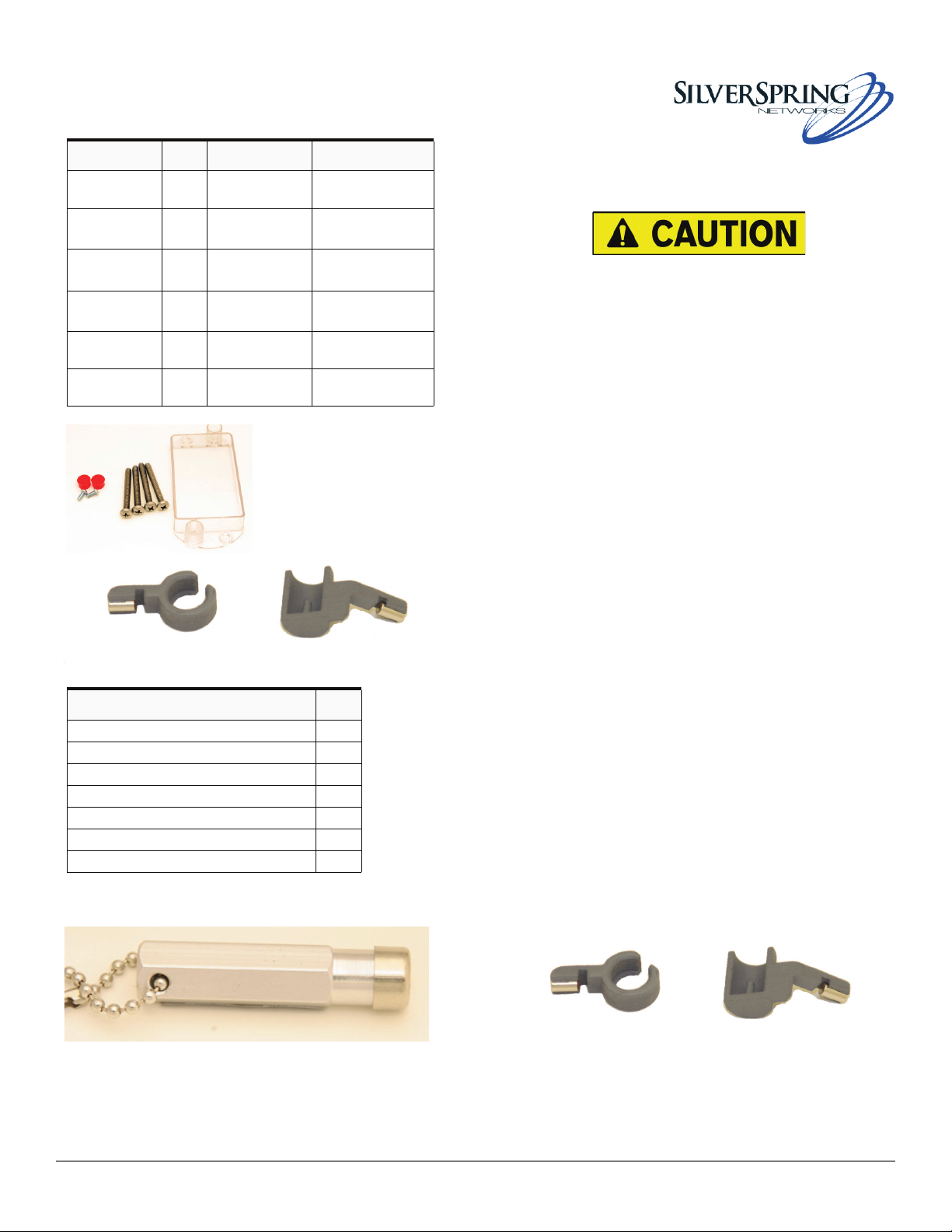
The components and tools you need to install the IMU are:
IMU Components
Component Qty. Size Part Numbers
SSN IMU 1 n/a 221-010001 (Am)
Index cover 1 n/a 976-000195 (Am)
Index cover
screws
Index screws 2 8-32 x
Red tamper
seals
Tamper magnet assembly
Figure 1. IMU Components
1/4
4
2 n/a 976-000204
1 n/a 976-000212 (Am)
-20” x 2
10-24 x 2
3/16”
6-32 x
3/4”
1/4”
1/4
”
222-010001 (RW)
976-000196 (RW)
901-000052 (Am)
901-000053 (RW)
901-000054 (Am)
901-000057 (RW)
976-000213 (RW)
Gas IMU Quick Install
Always follow applicable standards for safety. If you smell
gas, report it to the utility. Do not use power tools. Refer to
the meter documentation for further information.
The antennaof thistransmitter must not be co-located or operating in
conjunction with any other antenna or transmitter.
The device should be installed so that people will not come within 20 cm (8
in.) of the antenna.
This equipment has be en t est ed a nd found to comply with Part 15 of th e FC C
Rules. This equipment generates, uses and can radiate radio frequency
energy, and if not installed and used in accordance with the instructions,
may cause harmful interference to radio communications. However, there is
no guarantee that interference will not occur in a particular installation. If
this equipment does cause harmful interference to radio or television
reception, which can be determined by turning the equipment off and on,
the user is encouraged to try to correct the interference by one or more of
the following measures:
z Reorient or relocate the receiving antenna.
z Increase the separation between the equipment and receiver.
z Connect the equipment into an outlet on a circuit different from that
to which the receiver disconnected.
z Consult the dealer or an experienced Radio/TV technician for help.
Tools Required
Tool Qty
Flathead screw driver 1
Phillips screw driver 1
Nut driver 1
Awl 1
Scraper 1
Wire brush 1
Service magnet 1
Figure 2. Service Magnet
Modifications to the IMU not expressly approved by Silver
Spring Networks may void your authority to operate the
IMU.
To remove the existing index and prepare the meter:
1. Remove the existing index cover and index from the
meter.
2. Clean the meter index area and make sure to remove
any remaining parts of the old gasket.
Attach the tamper magnet assembly:
1. Attach the tamper magnet assembly to the meter as
shown.
On an American meter, attach the magnet
assembly so that the protrusion holding the magnet
points down and to the left and the gap in the
Part Number 220-008001 Gas IMU Quick Install
Page 2
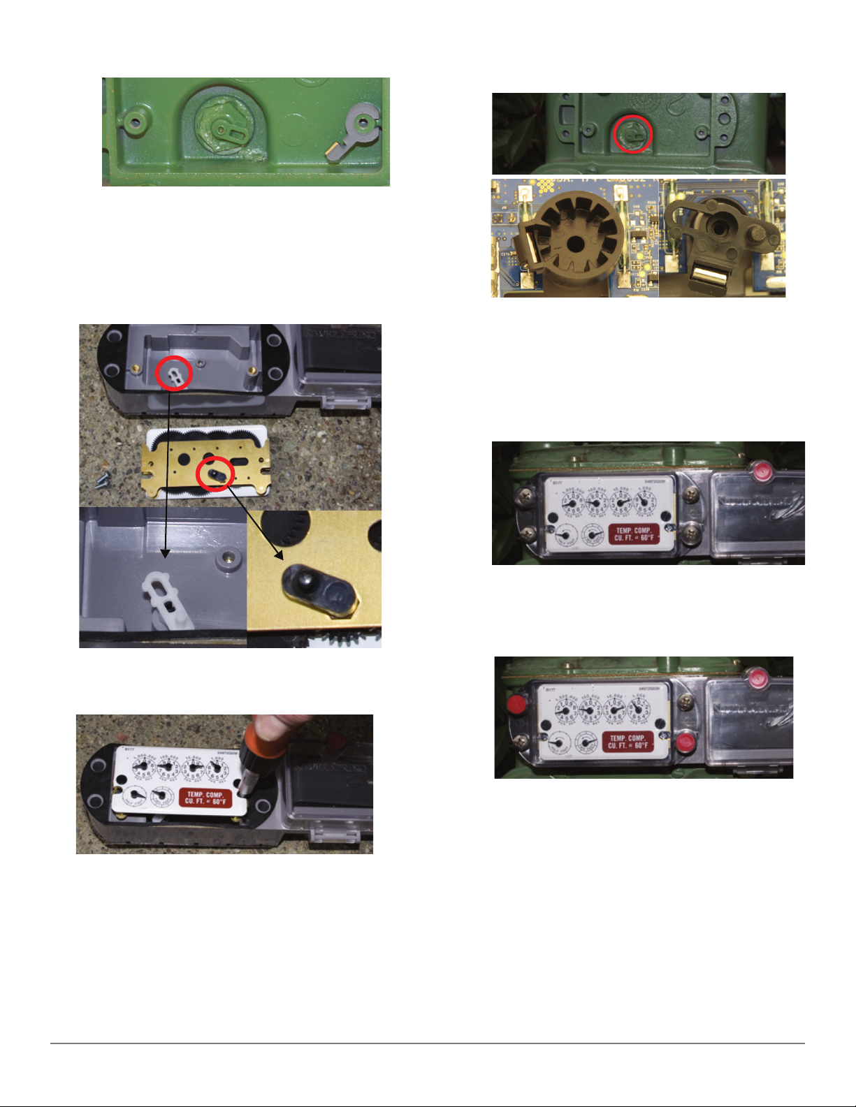
circle fits around the notch on the meter, as
shown:
On a Rockwell meter, attach the magnet assembly
so that the protrusion holding the magnet points
down and to the left and the inner pin is inserted
into the index screw hole.
Attach the meter index to the IMU:
2. Attach the IMU assembly to the meter so that the drive
train aligns with the meter wriggler and the screw holes
on the meter align with those on the cover.
1. Align the IMU drive train with the index wriggler.
2. Use the two index screws to firmly attach the index to
the IMU. (Torque: 13-15 in. lbs. for Rockwell; 14-17 in.
lbs. for American.)
Note: The photo above shows two types of
IMU drive train.
3. While holding the enclosure against the meter to
maintain proper alignment, rotate the test hand to
verify proper engagement.
4. Attach the index cover and screws to the meter.
5. Tighten the four screws firmly. (Torque: 17-20 in. lbs.
for Rockwell; 25-35 in. lbs. for American.)
6. Use the nut driver to push the two red tamper seals into
place.
3. Rotate the IMU drive train two turns, clo ckwise or
counter-clockwise to ensure it spins freely.
Attach the IMU assembly to the meter:
1. Insert the four cover screws through the index cover
and set the cover down.
Gas IMU Quick Install
Prepare the IMU for programming:
z Swipe the service magnet over the top of the IMU.
Doing so wakes up the IMU, enabling you to program it.
Refer to the documentation and training material for
programming the IMU.
 Loading...