

Page 1

I-210+ NIC and Meter Labeling
Product Requirements
Document Number 340-048002
VERSION DATE AUTHOR REVISIONS
1.0 4/13/07 B. Gilbert Initial version
1.1 5/14/07 B. Gilbert Change incorporates EUI-64 addressing
Silver Spring Networks – Confidential and Proprietary
NIC509Manual.doc
Page 2

I-210+ NIC and Meter Labeling
Product Requirements
1 Introduction
The I-210+ NIC is a FCC Part 15.247 compliant device that enables communica tion between
Silver Spring Networks AMI network and the I-210+ f amil y of mete r s . The NI C tr ansmits in the
902 to 928 MHz, ISM band and transfers data from utility meter to Silver Spring Networks Relays
and Gateways.
1.1 References
- Guidelines for use of a 64-bit Extended Unique Identifier (EUI-64), IEEE Publication.
2 Meter Labeling
2.1 Meter Nameplate
The meter nameplate shall not contain inf o rmation pertaining to the Silver Spring Networks
radio.
Figure 1 - Example of Meter Nameplate Label
Silver Spring Networks - Confidential and Proprietary
2
Page 3
I-210+ NIC and Meter Labeling
Product Requirements
2.2 Meter Auxiliary Label or NIC Address Label
For radio identification, the I-210+ meter shall have an auxiliary l abe l cont ain ing the Silver
Spring Networks NIC address presented in text (16 alphanumeric digits) and barcode formats.
• Bar Code Type = Code 3 of 9
• Bar Code Font Size = unknown
• Font Type = unknown
• Font Size = unknown
• Bar Code Label Dimensions = 1.50” x 0.25”
• Bar Code Material Type = Stati c Dissi pativ e Pol yimid e
The following fi gure is an example of the NIC address label, which is consistent with FCC
requirements set forth in section 4.1, and contain the Silver Spring Networks corporate name
and NIC EUI-64 address.
Figure 2 - Example of NIC Address Label
Silver Spring Networks
1234567890123456
Contains
FCC ID: OWS-NIC509, IC: 5975A-NIC509
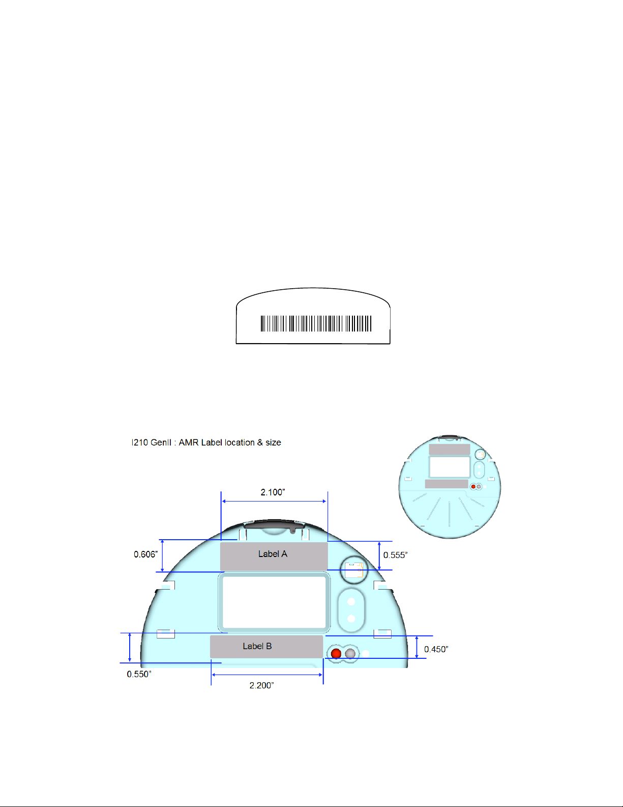
The NIC address label shall be place on the meter nameplate in the location identified by
“Label A” in the following figure.
NOTE: “Label B” location is not used.
Figure 3 – Nameplate NIC Address Locations
Silver Spring Networks - Confidential and Proprietary
3
Page 4
I-210+ NIC and Meter Labeling
Product Requirements
3 NIC Labeling
The SSN I-210+ NIC has two labels relevant to meter final assembly and RMA – the FCC & GE
Part Number label and the SSN NIC Address label. Both labels are located on the top side of the
NIC PCA. The barcode format is Code 3 of 9.
Figure 4 is an example of the FCC ID label that can be found in the location indicated in Figure
6. The size of the label is 1.5” x 1.0” inches. The barcode format is Code 3 of 9.
Figure 4 – FCC ID Label for NIC PCA
GE PN 123S123456
SSN PN 123-456789
FCC ID: OWS-NIC509 IC: 5975A-NIC509
This device complies with Part 15 of the FCC
Rules. Operation is subject to the following two
conditions: (1) this device may not cause harmful
interference, and (2) this device must accept any
interference received, including interference that
may cause undesired operation.
996-000015A
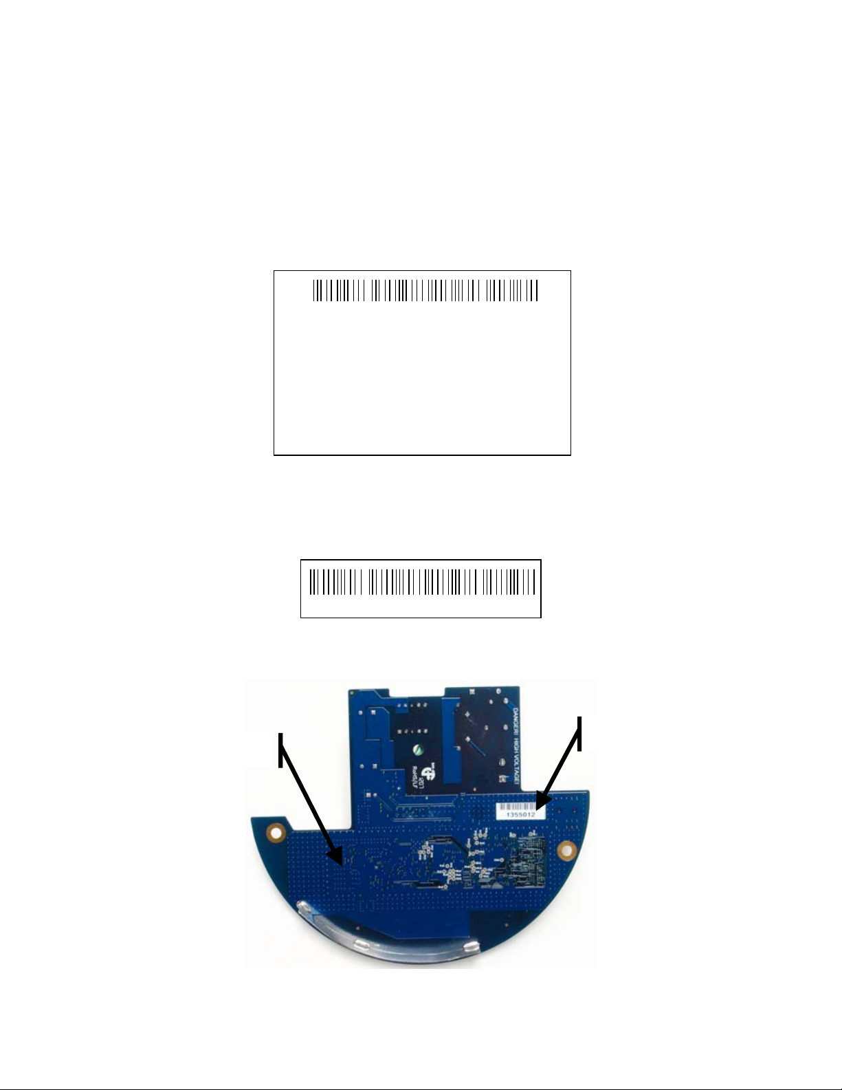
Figure 5 Figure 1is an example of the NIC address label that can be found in the location
indicated in Figure 6. The barcode format is Code 3 of 9.
Figure 6 – Label Locations on Top Side of I-210+ NIC PCA
FCC & GE Part
Number Label
Figure 5 – NIC Address Label for NIC PCA
1234567890123456
NIC Address
Label
Silver Spring Networks - Confidential and Proprietary
4
Page 5

I-210+ NIC and Meter Labeling
Product Requirements
Figure 7 – Bottom Side of I-210+ NIC PCA
SSN Corporate Name
SSN Model Number
4 FCC and Government Guidelines
Silver Spring Networks NIC
FCC ID: OWS-NIC509 IC: 5975A-NIC509
The I-210+ NIC is REQUIRED to be professionally installed by a properly trained technician.
Improper ins t a ll a tion co uld void the user ’ s a uthority to oper ate the equipment.
The device complies with Part 15 of the FCC rules. Operation is subject to the following two
conditions:
1. The de vi ce may not caus e harmful i nterfer e nce.
2. The device must accept any interference received, including interference that may cause
undesired oper ation .
Figure 8 – Sample FCC ID Label for NIC PCA
FCC ID: OWS-NIC50 9 IC: 5975A-NIC 509
This device complies with Part 15 of the FCC Rules. Operation
is subject to the foll owing two co nditions: (1) t his dev ice ma y
not cause harmful interference, and (2) this device must
accept any interference received, including interference that
may cause undesired operation.
Silver Spring Networks - Confidential and Proprietary
5
Page 6

I-210+ NIC and Meter Labeling
Product Requirements
NOTE: For FCC compliance, the following text MUST be included in I-210+ and I-210+c
meter manuals and user’s guides.
The antenna of this transmitter must not be co-located or operating in conjunction with any
other antenna or transmitter .
The device should be installed so that people will not come within 20 cm (8 in.) of the
antenna.
This equ ipment has be e n te st ed an d foun d to com ply with Pa rt 15 of t he FC C Rules. This
equipment generates, uses and can radiate radio frequency energy, and if not installed and
used in acco rdance with the in s truction s , m ay cau s e harmful interference to rad i o
communications. However, there is no guarantee that interference will not occur in a
particular installation. If this equipment does cause harmful interference to radio or television
reception, which can be determined by turning the equipment off and on, the user is
encouraged to try to correct the interference by one or more of the following measures:
• Reorient or relocate the receiving antenna.
• Increase the separation between the equipment and receiver.
• Connect the equipment into an outlet on a circuit different from that to which the receiver
disconnected.
• Consult the de aler or an experienced Radio/TV technician for help.
CAUTION: Changes or modifications not express l y approved by Silver Sprin g Net works could
void the user’s authority to operate the equipment.
4.1 FCC Guidelines for Devices Containing a Transmitter
Module
The following is an extract from FCC PART 15 UNLICEN SED MODU LAR TRANSMITTER
APPROVAL , DA 00-1407, Release d: June 26, 2000, Section 6 describing labeling
requirements for devices containing a modular transmitter.
Sec tion 6. The modular transmitter m ust be label ed wit h its own FCC ID
number, and, if the FCC ID is not visible when the module is installed inside
another device, then the outsi de of the device int o which the module is
installed must also display a label refe r r ing to the enclose d module. This
exterior label can use wording such as the following: “Contains Transmitter
Module FCC ID: XYZMODEL1” or “Contains FCC ID: XYZMODEL1.” Any similar
wording that expresses the same meaning may be used. The Grantee may
either provide such a label, an example of which must be included in the
application for equipment authorization, or, must provide adequate
instructions along with the module which explain this requirement.
In the latter case, a copy of these instructions must be included in the application for
equipment authorization."
Figure 9 – Sample FCC ID Label for Devices Containing a NIC
Contains FCC ID: OWS-NIC509, IC: 5975A-NIC509
Silver Spring Networks - Confidential and Proprietary
6
Page 7

I-210+ NIC and Meter Labeling
Product Requirements
4.2 Safety Information
WARNING!: Severe shock and explosion hazard! Touching energized parts can result in massive
equipment damage, and severe injury or death. Short-circuiting energized parts will result in
blinding flash and explosion. Opening and closing electrical circuits can also produce dangerous
and explosive arc flashe s. Involuntary muscular reaction s assoc iated with electrical shock may
result in other injuries. Observe the following safety guidelines.
Careful planning of every job is essential. Nothing should be taken for granted. Do not take
chances!
• Read and follow all approved policies and procedures provided by your employer associated
with the procedures in this manual.
• The procedures in th is manual mu st only be performed by qua lif ied workers in acc o rdanc e
with local utility safety practices, utility requirements, and applicable OSHA and NFPA
standards.
• The information contained in this document is intended to aid qualified personnel, and is
not a replacement for the proper training required to make a person qualified.
• Silver Spring Networks assumes no liability for the customer’s failure to follow these safety
guidelines.
4.3 General Electrical Safety
• Perform the procedure s in this manu al in accord ance with applicable workplace standar d s
establi shed by the follow ing agencies:
• Occupational Safety and Health Act (OSHA).
• The N a tional Electri cal Code published by the Nat ional Fire Protection Asso ciation
(NFPA-70).
• National Elect r ical Manuf actu re r s Association (NEMA).
• Electronics Industr ies Association (EIA).
• Insulated Power Cable Engineer s Association (IPCEA).
• American National Standards Institute (ANSI). Whenever possible, de-energize all circuits or
equipment before wor king on them.
• Maintain a minimum clearance of 10 ft. between line potential and all unqual ified persons
at all times.
• Keep unauthori z ed pe opl e o ut of the work area. Be espe cially cau tious of children, who
tend to be drawn to work activity.
• Determining if a circuit is OFF can be difficult in some instances. Check for circuit voltage
with an appropriate voltmeter before working on equipment presumed to have been deenergized. Tiebreakers, double throw disconnect switches, automatic transfer switches and
emergency generators can supply power through an alternate circuit or from another
source.
• 120V current can be just a lethal as higher voltages because current flow through a body
depe nd s upon th e b ody’s res i stan c e.
• Do not trust insulation a nd/or weathe rproofing on a wire as p rotection from shock.
• Use electrically insulated tools. Inspect portable electrical equipment or tools for defects
and remove any defective devices from service immediately. All portable electrical
equipment must have Ground Fault Circuit Interrupter (GFCI) protection.
• Select the right tool for the job. Use tools properly. Keep tools in good working order.
• Make sure the work area is free of any flammable material. Flammable vapors can be
ignited by an arc flash.
• Keep the work area cle an and dry. Cluttered wor k areas cause accident s and inj uries.
Silver Spring Networks - Confidential and Proprietary
7
Page 8

I-210+ NIC and Meter Labeling
Product Requirements
• Provide good lighting in the work area. You cannot work safely if you cannot see what you
are doing.
• Report unsafe conditions or defective equipment to your immediate supervisor.
• Hand le material carefu lly. Lift and car ry p roperl y.
4.4 Personal Protective Equipment (PPE)
• Always wear Personal Protective Equipment (PPE), in accordance with OSHA and ANSI
standards.
• Wear eye protection and electrically insulated gloves. Test gloves in accordance with ANSI
standa rds bef o re use. Do not use glov es that do no t p ass app r opriate test pr ocedu res .
• Wear protective clothing such as long sleeve shirts and long pants made of flame resistant
materials.
• Remove all jewelry.
• Do not pass any objects to or from other persons not protected by insulating platforms or
tested, electrically insulated gloves.
4.5 Fall Protection
When performing work at any elevation:
• Always use a fall protection system, in accordance with OSHA standards, whenever
performin g work at any elevation.
• Never use conductors, guy wires, pins, or cross-arm braces, etc. to support your weight.
• Whenever using aerial lift devices such as hoists, man-lifts, vehicle-mounted work
platform s and overhead lifts, read and follow the manufactu rer’s guidelines for safe and
proper operation .
• Use ladders and scaffolding only in accordance with the manufacturer’s guidelines and/or
according to OSHA standards .
• Only use ladde r s m a d e o f non-m eta llic, non-co nductiv e m a terial . T h ey should be the
proper size and type for the work intended. Inspect ladders for wear and breakage.
Remove any oil, grease, or other slippery materials.
• Do not set the ladder at too steep or too shallow of an angle. A rule of thumb is to stand
erect with your toes against the bottom rails of the ladder, with your arms extended
straight out. If you can set your palms on top of the rung that is at eye level, the ladder
should be at the p ro p er angle. If a ladder angle label is provided , follow its
recommendatio ns.
• If the ladder is to remain in place for an extended period, secure it at the top. The support
point at the top of the ladder should be at least 24 inches (60 centimeters) wide to
maintain support in the event of sideways movement. For jobs of short duration, have a
fellow worker support the ladder at the base.
• Evaluate all tasks to be performed from a ladder for potential fall hazards, such as complex
tasks or situations that require leaning from the side of the ladder.
• The use of scaffolding or a work platform shou l d be consid er ed as an altern ative solution in
such cases.
4.6 Shock Accident First Aid
• Do not touch the victim with your bare hands; use something non-conductive to separate
the vict im from the energy s ource.
Silver Spring Networks - Confidential and Proprietary
8
Page 9

I-210+ NIC and Meter Labeling
Product Requirements
• Call for emergency medical help immediately. Keep the victim lying down, warm, and
comfo rta b le until help arrives. Avo id movi ng t he victim in ca s e of injur y to neck or b a ck .
Position an unconscious victim on a side to let fluids drain.
• Check the victim’s breathing and heartbeat. If properly trained, apply mouth-to-mouth
resuscitation and/or CPR if necessary.
• Remove constricting items from the victim, such as shoes, belts, jewelry, and tight collars;
they co ul d cut off ci r c ul ation i f the victim exper iences swelli ng.
• Apply water or saline for a few minutes to any burns until the skin returns to normal
temperature. Do not attempt to remove clothing that is stuck to a burn. If possible,
elevate burned areas to reduce swelling.
• Make sure the victim receives professional medical attention, even if they feel fine.
Electric shock can cause heart failure hours after the shock is received.
Silver Spring Networks - Confidential and Proprietary
9
 Loading...