

Page 1

Understanding Silver Spring
Networks Access Points
Silver Spring Networks
555 Broadway Street
Redwood City, CA 94063
www.silverspringnet.com
Page 2

Understanding Silver Spring Networks Access Points
Please consider the environment before printing this document.
Copyright © 2013 Silver Spring Networks, Inc. All rights reserved.
®
The Silver Spring Networks logo, UtilityIQ
, and UtilOS® are registered trademarks of Silver S pri ng Networks, Inc.
GridScape™, CustomerIQ™, and Direct-to-Grid™ are trademarks of Silver Spring Networks, Inc.
All other company and product names are used for identification purposes only an d may be registered tr ademarks,
trademarks, or service marks of their respective owners.
Revisions
Number Date Revision
3 January 2013 Updated NIC 40 references to NIC 45, data rate for 900-MHz
communications in Table 1, information in the sample FCC ID label, and
changed references to DRM to HCM.
2 December
2012
Added FCC and Government Guidelines section, revised EU regulatory
information. Added 2.4 GHz to Specifications. Updated standards
compliance specifications and corrected voltage range information.
1 10 Aug 2012 Updated supported frequencies for Luxembourg, United Kingdom, Portugal,
and New Zealand; added EU regulatory information.
Customer Support
Country Email Telephone Hours
Australia aus-support@silverspringnet.com 1300 706 769 9:00 AM - 9:00 PM
Australia Eastern Time
Canada support@silverspringnet.com Toll free:
1-888-SSN-9876
(1-888-776-9876)
Worldwide +1-650-298-4298
Contact us on the Web http://www.silverspringnet.com/services/customer-support.html
5:00 AM - 6:00 PM
US Pacific TimeUnited States
Understanding Silver Spring Networks Access Points Rev 3 22 January 2013 Silver Spring Networks 2
Page 3

Understanding Silver Spring Networks Access Points Contents
Content s
1. About Access Points. . . . . . . . . . . . . . . . . . . . . . . . . . . . . . . . . . . . . . . . . . . . . . . . . . . . . . . 4
Overview. . . . . . . . . . . . . . . . . . . . . . . . . . . . . . . . . . . . . . . . . . . . . . . . . . . . . . . . . . . . . . . . . . . . . . . . 4
Features . . . . . . . . . . . . . . . . . . . . . . . . . . . . . . . . . . . . . . . . . . . . . . . . . . . . . . . . . . . . . . . . . . . . . . . . 5
AP Product Description . . . . . . . . . . . . . . . . . . . . . . . . . . . . . . . . . . . . . . . . . . . . . . . . . . . . . . . . . . . . 5
Battery Backups . . . . . . . . . . . . . . . . . . . . . . . . . . . . . . . . . . . . . . . . . . . . . . . . . . . . . . . . . . . . . . . . 6
Read Storage . . . . . . . . . . . . . . . . . . . . . . . . . . . . . . . . . . . . . . . . . . . . . . . . . . . . . . . . . . . . . . . . . . 7
Power Requirements . . . . . . . . . . . . . . . . . . . . . . . . . . . . . . . . . . . . . . . . . . . . . . . . . . . . . . . . . . . . 7
Rebooting or Recycling APs . . . . . . . . . . . . . . . . . . . . . . . . . . . . . . . . . . . . . . . . . . . . . . . . . . . . . . . 7
Standards Compliance . . . . . . . . . . . . . . . . . . . . . . . . . . . . . . . . . . . . . . . . . . . . . . . . . . . . . . . . . . . 7
Cellular Modem . . . . . . . . . . . . . . . . . . . . . . . . . . . . . . . . . . . . . . . . . . . . . . . . . . . . . . . . . . . . . . . . . 8
Addressing Schemes . . . . . . . . . . . . . . . . . . . . . . . . . . . . . . . . . . . . . . . . . . . . . . . . . . . . . . . . . . . . 8
Specifications . . . . . . . . . . . . . . . . . . . . . . . . . . . . . . . . . . . . . . . . . . . . . . . . . . . . . . . . . . . . . . . . . . 9
European Union Compliance . . . . . . . . . . . . . . . . . . . . . . . . . . . . . . . . . . . . . . . . . . . . . . . . . . . . . 10
Maintenance Procedures . . . . . . . . . . . . . . . . . . . . . . . . . . . . . . . . . . . . . . . . . . . . . . . . . . . . . . . . 12
Surge Protection . . . . . . . . . . . . . . . . . . . . . . . . . . . . . . . . . . . . . . . . . . . . . . . . . . . . . . . . . . . . . . . 12
Redundant WAN Option . . . . . . . . . . . . . . . . . . . . . . . . . . . . . . . . . . . . . . . . . . . . . . . . . . . . . . . . . 12
Mounting Options . . . . . . . . . . . . . . . . . . . . . . . . . . . . . . . . . . . . . . . . . . . . . . . . . . . . . . . . . . . . . . 12
WAN Options . . . . . . . . . . . . . . . . . . . . . . . . . . . . . . . . . . . . . . . . . . . . . . . . . . . . . . . . . . . . . . . . . 12
Throughput Performance . . . . . . . . . . . . . . . . . . . . . . . . . . . . . . . . . . . . . . . . . . . . . . . . . . . . . . . . 13
Responding to a WAN Failure . . . . . . . . . . . . . . . . . . . . . . . . . . . . . . . . . . . . . . . . . . . . . . . . . . . . 16
Multicast / Unicast Communications . . . . . . . . . . . . . . . . . . . . . . . . . . . . . . . . . . . . . . . . . . . . . . . . 16
Networking . . . . . . . . . . . . . . . . . . . . . . . . . . . . . . . . . . . . . . . . . . . . . . . . . . . . . . . . . . . . . . . . . . . 16
Address Management . . . . . . . . . . . . . . . . . . . . . . . . . . . . . . . . . . . . . . . . . . . . . . . . . . . . . . . . . . . 17
Administration. . . . . . . . . . . . . . . . . . . . . . . . . . . . . . . . . . . . . . . . . . . . . . . . . . . . . . . . . . . . . . . . . . . 17
Configuration . . . . . . . . . . . . . . . . . . . . . . . . . . . . . . . . . . . . . . . . . . . . . . . . . . . . . . . . . . . . . . . . . . . 18
2. FCC and Government Guidelines. . . . . . . . . . . . . . . . . . . . . . . . . . . . . . . . . . . . . . . . . . . . 19
FCC Guidelines for Devices Containing a Transmitter Module . . . . . . . . . . . . . . . . . . . . . . . . . . . . . 20
External Antenna Integration . . . . . . . . . . . . . . . . . . . . . . . . . . . . . . . . . . . . . . . . . . . . . . . . . . . . . 20
Safety Information . . . . . . . . . . . . . . . . . . . . . . . . . . . . . . . . . . . . . . . . . . . . . . . . . . . . . . . . . . . . . . . 21
General Electrical Safety . . . . . . . . . . . . . . . . . . . . . . . . . . . . . . . . . . . . . . . . . . . . . . . . . . . . . . . . . . 21
Personal Protective Equipment (PPE) . . . . . . . . . . . . . . . . . . . . . . . . . . . . . . . . . . . . . . . . . . . . . . . . 22
Fall Protection. . . . . . . . . . . . . . . . . . . . . . . . . . . . . . . . . . . . . . . . . . . . . . . . . . . . . . . . . . . . . . . . . . . 22
Shock Accident First Aid. . . . . . . . . . . . . . . . . . . . . . . . . . . . . . . . . . . . . . . . . . . . . . . . . . . . . . . . . . . 23
Index . . . . . . . . . . . . . . . . . . . . . . . . . . . . . . . . . . . . . . . . . . . . . . . . . . . . . . . . . . . . . . . . . . . . . 24
Understanding Silver Spring Networks Access Points Rev 3 22 January 2013 Silver Spring Networks 3
Page 4
Understanding Silver Spring Networks Access Points 1 About Access Points
1 About Access Points
Overview
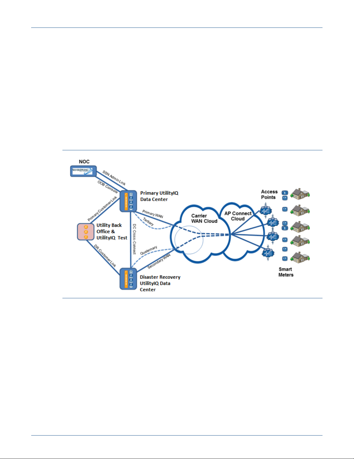
The Silver Spring Access Point (AP) provides the central link between endpoint devices and
network control and monitoring. It is the connectivity between intelligent endpoints and the
utility’s back office. Its flexible communication features extend the reach and coverage of the
network to thousands of customer premises, through scalability that lowers ownership costs.
Since it has a backup battery, the AP can reliably route scheduled read and management
tasks, even during an outage. Figure 1 illustrates how APs connect endpoints to the utility
back office (UtilityIQ data centers).
Figure 1. The AP in the network
The Access Point can be mounted on power poles or street lamps. All outbound
communications (requests for data) pass through the AP. All inbound data packets (data,
alarms) pass through the AP.
The AP can serve as the take-out point for network management traffic in a stand-alone
communication network (or also for Advanced Metering Infrastructure—AMI, Distribution
Automation—DA, or HAN Communications Manager (HCM)—HCM traffic in a joint
AMI/DA/HCM installation). In certain cases, the AP can be the take-out point for traffic.
It is worth noting that the Silver Spring architecture differs from most others in that the AP is
not what utility companies typically call a collector or concentrator—it is a router. This
means that memory limits and data vulnerability issues typical of “collector” architecture are
eliminated resulting in a more robust, scalable, simpler and higher performance network.
The Access Point comes with a 902-928 MHz-based radio Neighborhood Area Network (or
NAN) interface which can be configured with any cellular technology (for example, Code
Understanding Silver Spring Networks Access Points Rev 3 22 January 2013 Silver Spring Networks 4
Page 5

Understanding Silver Spring Networks Access Points 1 About Access Points
Division Multiple Access, Long Term Evolution, High Speed Packet Access, single carrier
Radio Transmission Technology) Wide Area Network (WAN) interface, or with a 10/100
Ethernet interface. The Access Point provides a method for implementing the last mile utility
information and control network.
Features
The features of the Silver Spring Access Point are:
• Full two-way, 870-876 and 902-928 MHz FHSS
• One-watt transmitter
• Dynamic network discovery and self healing
• Robust security from the endpoint through to the wide area network
• “Over-the-air” network firmware upgrades
• Sophisticated routing functions ensure multiple paths to each endpoint
• Automated scheduling and network management tasks
• Long-reach, multi-hop networks, providing high endpoint-to-Access Point deployment
ratios
• Weather-resistant outdoor enclosure, for longer life and greater durability
• Battery backup option (highly recommended) for fault-tolerant operation
AP Product Description
The types of APs available are:
Cellular APs, Satellite APs, Pad-mount APs, and Ethernet APs. The Ethernet APs can be
configured with 10/100BaseT, and Fiber interfaces.
Cellular and Ethernet Access Points are shipped pre-configured. For cellular Access Points,
Silver Spring will work with the chosen cellular provider to facilitate Access Point turn-up.
For Ethernet Access Points, Silver Spring will work with the client on IP addressing to allow
Silver Spring to pre-configure field devices for quick field implementation.
Understanding Silver Spring Networks Access Points Rev 3 22 January 2013 Silver Spring Networks 5
Page 6
Understanding Silver Spring Networks Access Points 1 About Access Points
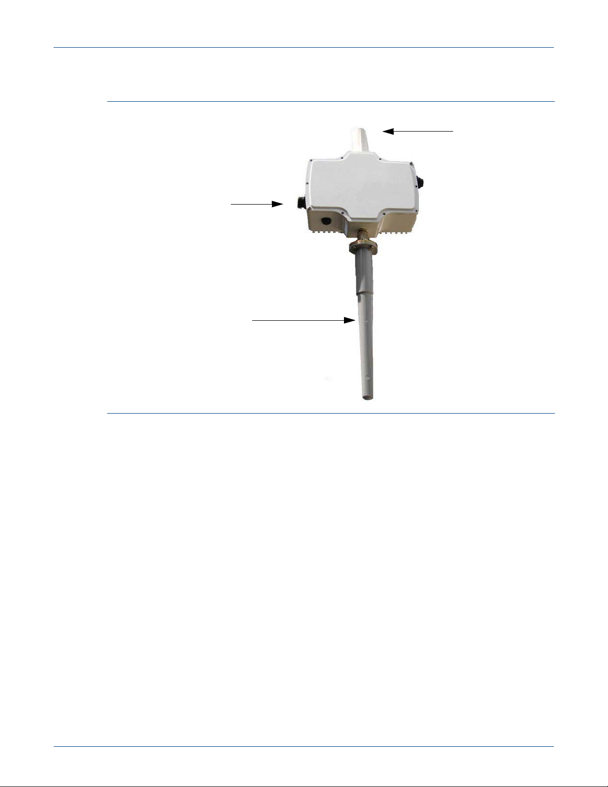
Cellular antenna
Power
connector
NAN antenna
Figure 2 shows an Ethernet AP.
Figure 2. Silver Spring Networks Access Point (AP)
Battery Backups
APs can be configured with battery backups. In the event of a power failure, the battery
backup can provide continuous operation for at least eight hours.
Silver Spring Networks suggests as a best practice, a battery backup within the Access Point.
When operating on battery backup, Access Points maintain full operational features. The
Infrastructure Battery Pack (IBP) uses sealed lead-acid battery technology, which will deliver
energy over a -40 to +85C temperature range. Silver Spring operates the Infrastructure
Battery Pack on a float (that is, the usage model is defined as long periods of topped-off
charge states followed by sporadic deep discharge events (outage events).
UtilityIQ
severity from informational (for example, export job succeeded) to warning (for example, the
gap filler has started running because an interval gap was detected), to error (for example,
the DC Detection flag on the meter was set), to emergency. These include an alarm when the
backup battery on an Access Point is critically low.
For more information on battery backup devices, refer to www.enersys.com. The key
documents are:
• Cyclon Application Manual
• Cyclon Selection Guide
®
, GridScape, or HCM applications can actively monitor status. Events range in
Understanding Silver Spring Networks Access Points Rev 3 22 January 2013 Silver Spring Networks 6
Page 7

Understanding Silver Spring Networks Access Points 1 About Access Points
The design float life of Silver Spring-IBP products is up to eight (8) to ten (10) years at room
temperature (25°C/77°F) and under proper charging conditions. This design life has been
confirmed by the use of accelerated testing methods that are widely accepted by both
manufacturers and users of sealed-lead batteries. High temperatures are used to accelerate
the aging process of the battery under test.
Read Storage
The Access Point has 8MB of RAM and 8MB of Flash. No reads are stored within the Access
Point.
Power Requirements
The Access Point and Relay require 96 to 250 VAC (50 to 60 Hz).
Power can be tapped directly from the power line or from a street light receptacle.
Rebooting or Recycling APs
Silver Spring Networks APs will run steady state for an indefinite period of time. Reboots are
not contingent upon any inherent tendency for the AP to reboot itself. The only conditions
that would manifest a reboot are:
• Power failure in the absence of battery backup
• WAN dialer reaches a “high water count” that induces a firmware reboot – this happens
when cellular coverage is intermittent
• Upgrade of firmware
• Deliberate reboot instruction issued from field technician or from back-office
Standards Compliance
APs comply with:
• Operating Vibration standard ANSI C12.20, IEC 60068-2-8
• Operating Shock standard ANSI C12.20, IEC 60068-2-27
• Humidity standard ANSI C12.20, IEC 60068-2-6
• Operating Temperature standard ANSI C12.20, IEC 60068-2-1, IEC 60068-2-2
• Electromagnetic Susceptibility standard ANSI C12.20, IEC 61000-4-3
• Surge Withstand Capability standard ANSI C12.20, IEC 61000-4-5
• Electrostatic Discharge standard ANSI C12.20, IEC 61000-4-2
• Electrical Fast Transients per ANSI C12.20, IEC 61000-4-4
• Conducted Immunity per IEC 61000-4-6
• Magnetic Immunity IEC 61000-4-8
• Voltage Dips & Interrupts IEC 61000-4-11
• Safety Standard for Information Technology Equipment, IEC 60950-1, IEC 60950-22
Understanding Silver Spring Networks Access Points Rev 3 22 January 2013 Silver Spring Networks 7
Page 8
Understanding Silver Spring Networks Access Points 1 About Access Points
Cellular Modem
Currently, the modem is a Sierra Wireless AirLink, RavenX, RavenXT, or RavenXE
depending on AP model and country location.
Addressing Schemes
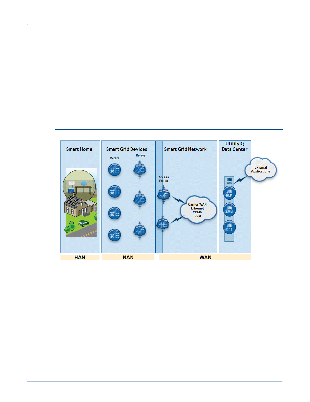
Silver Spring’s addressing scheme is based on the Internet Protocol (IP) suite. Each network
device has one or more IPv6 addresses within the LAN. The Access Point will typically have
an IPv4 address assigned to the WAN side. A 6in4 tunnel carries the data over a cellular
carrier or Ethernet-based backhaul to the head end, where the tunnel is terminated, and IPv6
traffic is carried through to UtilityIQ, GridScape, or HCM. A high-level conceptualization of
the NAN-to-WAN networks that AP traffic traverses is shown in Figure 3.
Figure 3. APs in the Silver Spring Network
The Access Point is the central link between the utility’s enterprise management systems and
the endpoint devices such as Silver Spring-enabled electricity, water, gas meters, bridges,
External Communications Modules, and Fault Circuit Indicators.
The Access Point is a vital part of the smart grid network, which extends secure, real-time
measurement and control interfaces (with full, two-way communications) throughout the
network and to the customer premises.
The Access Point provides a highly reliable connection to RF devices over a NAN. It
communicates with intelligent endpoints, including meters and Bridges. The Access Point
can also pass information through multiple Silver Spring Relays or through Silver Spring enabled electricity meters or Master Bridges. And it offers multiple paths to each endpoint,
through sophisticated mesh network routing that ensures greater reliability and redundancy.
The Access Point also provides WAN connectivity to your utility’s mission-critical
applications through digital cellular or Ethernet connections.
Understanding Silver Spring Networks Access Points Rev 3 22 January 2013 Silver Spring Networks 8
Page 9

Understanding Silver Spring Networks Access Points 1 About Access Points
Specifications
The AP hardware specifications are listed in Table 1.
Table 1. Access Point specifications
Feature Description
900-MHz Communications:
Data rate 100 - 300 Kbps
Frequencies 902-928 MHz North America
915-928 MHz Australia
902-907.5, 915-928 MHz Brazil
870-876 MHz Luxembourg & United Kingdom
870-873 MHz Portugal
922-928 MHz New Zealand
Spread Spectrum technology FHSS
Transmitter output 30 dBm
Output impedance 50 ohms
Receiver sensitivity -97 dBm for 1% PER
WAN Cellular, Ethernet, Satellite
2.4-GHz HAN Transceiver:
Frequency range 2.4 GHz, ISM Band
Data rate 100Kbps - 1Mbps FHSS
Spreading technique
Transmitter output Output Power: 20-27dBm FHSS
Receiver sensitivity -97 dBm for 1% PER
Power Draw TX 1.8 W typ. (2.0 W max.)
Physical Interfaces:
Antenna connector N Type, Female
NAN antenna Omni antenna with gain not to exceed 3.6dBi on 2.4GHz and 3.0dBi
Cellular antenna Mobile Mark antenna RMM-UMB-1S-WHT-7
Protocols/Security:
Addressing Internet Protocol Version 6 (IPv6)
Security Secure Hash Algorithm 256 bit (SHA-256) RSA-1024 and /or ECC-
Encryption AES-128 or AES-256
Mechanical:
Cellular 24cm (9.5”) L x 25cm (10”) W x 13cm (5.2”) H, 2.38kg (5.1 lbs.)
Ethernet 23cm (9”) L x 20cm (8”) W x 10cm (4”) H, 1.8kg (4 lbs.) weight, IP65,
Underground (cellular) 34cm (13.5”) L x 29cm (11.5”) W x 15cm (6”) H, 6.2kg (13.6 lbs.)
FHSS
on 900MHz
256
weight, IP65, white, aluminum housing
white, aluminum housing
weight, IP67, fiberglass reinforced polyester (FRP) housing
Understanding Silver Spring Networks Access Points Rev 3 22 January 2013 Silver Spring Networks 9
Page 10

Understanding Silver Spring Networks Access Points 1 About Access Points
Table 1. Access Point specifications (Continued)
Feature Description
Environmental:
Operating Temperature: -40°C to +70°C (-40°F to +158°F)
Humidity: 0% to 95%, no n-condensing
Power
Voltage Range: 96 to 250 VAC, ~ 1A, 50 to 60Hz
Power Consumption Idle Maximum
Ethernet 2.5W, 7W
Ethernet with battery 2.5W, 8W
Cellular 2.5W, 12.5W
Cellular with battery 2.5W, 13.5W
Battery Backup Option: > 8 hour operation
Receive Sensitivity
Mounting Kit Options:
Pole Wooden, concrete, light
Other Wall, pad
Approvals:
FCC Part 15.247
Industry Canada RSS-210
Receive sensitivity is -102 dBm @ 10
-6
BER.
European Union Compliance
This section describes Silver Spring Networks’ compliance with the EU R&TTE Directive.
The Access Point 1.5i uses a one Watt FHSS radio. Licenses have been issued as follows:
• Luxembourg
A license has been obtained from ILR (Institut Luxembourgeois de Regulation) to operate
in Luxembourg in the 870-876 MHz band.
• United Kingdom
A license has been obtained from Ofcom to operate in UK in the 870-876 MHz band.
• Portugal
A license has been obtained from ANACOM to operate in Portugal in the 870-873 MHz
band.
This device has been designed to operate with and certified for antennas that have a
maximum gain of 3.0dBi on 900MHz and 3.6dBi on 2.4GHz. Antennas that have a gain
greater than specified are strictly prohibited for use with this device. The required antenna
impedance is 50 ohms.
Installation of all antenna radiating elements shall have a minimum separation distance of 20
cm from all persons and must not be co-located or operating in conjunction with any other
transmitter.
Understanding Silver Spring Networks Access Points Rev 3 22 January 2013 Silver Spring Networks 10
Page 11

Understanding Silver Spring Networks Access Points 1 About Access Points
Declaration of Conformity with regard to the R&TTE Directive 1999/5/EC
This declaration is only valid for configurations (combinations of software, firmware, and
hardware) provided and supported by Silver Spring Networks Inc. The use of software or
firmware not provided and supported by Silver Spring Networks Inc. may result in the
equipment no longer being compliant with the regulatory requirements.
Note: The equipment is in compliance with the essential requirements and other relevant
provisions of Directive 1999/5/EC.
The following standards were applied:
• EMC: EN 55022 (2010), EN 55024(2010), EN 61000-3-2 (2006)
EN 61000-3-3 (2008), ETSI EN 301 489-3 v1.4.1
• Safety: EN 60950-1:2006, EN 60950-22:2006, BS-EN 62311 (2008)
• Radio: ETSI EN 300 220-1 v2.3.1 (2010-02), ETSI EN 300 220-2 v2.3.1 (2009-12),
The conformity assessment procedure referred to in Article 10 and detailed in Annex IV of
Directive 1999/5/EC has been followed.
Note: This equipment is intended to be used in Luxembourg, United Kingdom, and Portugal in
conjunction with licenses. For more details, contact Silver Spring Networks Compliance.
The product carries the CE Mark:
A copy of the Declaration of Conformity may be obtained with formal request to:
Silver Spring Networks, c/o Hardware Engineering
555 Broadway Street
Redwood City, CA 94063, USA
Declaration of Conformity for RF Exposure
This system has been evaluated for RF exposure for Humans in reference to EN 62311(2008)
Assessment of electronic and electrical equipment related to human exposure restrictions for
electromagnetic fields (0 Hz – 300 GHz). The minimum separation distance from the antenna
to general bystander is 20cm (7.9 inches).
Installation Note
Since APs do not have a power on/off switch for disconnecting AC power before servicing,
AC power is provided through an AC mains disconnect switch or breaker. Therefore, the
electrical installation of this product is under the control of the power utilities or their
authorized subcontractors. Refer to their procedures for further instructions.
Only certain types of batteries can be used for battery replacements. Contact Silver Spring
Networks for information about equivalent battery types that can be used for replacement.
Understanding Silver Spring Networks Access Points Rev 3 22 January 2013 Silver Spring Networks 11
Page 12

Understanding Silver Spring Networks Access Points 1 About Access Points
Maintenance Procedures
If an Access Point experiences an outage, all end point devices and Relays that were
associated with it will converge on their secondary Access Point as found within their
NodeQs. This alleviates outages due to Access Point failure. UtilityIQ-Network Element
Manager (NEM), GridScape, or HCM is then alerted of an Access Point outage, and forwards
this message to the operator. Spare pre-configured Access Points are kept on hand, and are
scheduled for network insertion within the utilities work order management system. Within
NEM, GridScape, or HCM, the failed Access Point is flagged for RMA, and the device is
replaced.
Surge Protection
APs comply with up to 20kV for combination wave and up to 6kV for ring waves (reflects the
current Ethernet AP and projected assembly.)
Redundant WAN Option
WAN redundancy is inherent to the routed Mesh being offered by Silver Spring Networks.
Access Points have the ability to identify WAN outages and forward traffic to secondary
Access Points through their 902-928 FHSS interface. There is no downtime realized and as
routes to the WAN become unavailable, those routes age out of the route tables of adjacent
nodes as would be expected in a full-mesh network that continuously updates node queues
and route tables. When an AP becomes unavailable, the routed Mesh dynamically
reconfigures to available APs. When the AP comes back online, the routed Mesh dynamically
reconfigures to include the AP in the Mesh network.
It is the suggestion of Silver Spring that multiple cellular carriers be spread across the
territory to reduce the impact of a wide scale cellular outage. In addition, the co-mingling of
private backhaul such as private network found within substations is also an option. The
Silver Spring Networks Access Point can use public or private backhaul technologies to
communicate to the host system (UtilityIQ, GridScape, or HCM) at the Utility head end. An
AP can have a cellular modem (such as those approved for use on CDMA or General Packet
Radio Service (GPRS) systems from Sprint, AT&T, Telus or other carrier) or any broadband
technology that is Ethernet/IP compatible (such as Wi-Fi, fiber, private microwave or
WiMAX). Current Silver Spiring customers are using cellular modems, fiber backhaul, and
private licensed and unlicensed wireless backhaul technologies. Additionally, some
customers are currently experimenting with satellite backhaul connections and will be
deploying this technology where needed.
Mounting Options
The Access Points can be mounted on a utility pole or light pole. The can be pad mounted as
well as wall mounted. (For additional information, refer to the Silver Spring Networks
Infrastructure Hardware Guide.) Silver Spring recommends that the units be mounted at a
height of 7 to 9 meters.
WAN Options
Any WAN backhaul that can interface with the Access Point’s Ethernet port and provide
IPv4 connectivity to the HES with a minimum of 40kbps can be used as backhaul.
Understanding Silver Spring Networks Access Points Rev 3 22 January 2013 Silver Spring Networks 12
Page 13

Understanding Silver Spring Networks Access Points 1 About Access Points
Customers have used the following alternative backhaul technologies:
• Distribution Substation Backhaul (for example, fiber)
• WiMAX
• Satellite Radios
The design rule for Access Point to RF devices is 1 to 5,000. At this ratio, the maximum data
throughput required from a WAN solution is 40kbps per Access Point.
Based on real-world data on a network of this size, the average wireless speed is measured at
2.6Mbps downstream and 700Kbps upstream, which is well in excess of requirements.
The backhaul is fairly insensitive to latency (that is, in remote locations, Silver Spring already
proven successful connection using satellite radios which have a ~1.5s RTT - or Round Trip
Time).
Silver Spring recommends that the network design for a particular deployment limit
exposure to single points of failure and proactively design for redundancy by allowing each
RF device to be reached from more than one Access Point. In all but rural densities, having
up to 5,000 RF devices per AP generally results in most RF devices being able to reach more
than one Access Point.
Throughput Performance
Typical data packet sizes observed in Smart Grid systems is between 150 bytes for DA or
other simple command and control applications. A normal HCM and AMI meter read packet
is approximately 350 bytes including full measurement intervals, event logs, and
instantaneous register reads. At 100 Kbps (10 bytes / ms), delivery of 150 byte packets occurs
at 10 full transactions per second.
The larger AMI/HCM packets are delivered at 3-5 transactions per second. These are typical
observed rates and it should be mentioned that for reliability reasons all transactions are
completely acknowledged four-way confirmed events.
Though final data is not available, raising on-air data rates from 100 Kbps to 300 Kbps will
roughly double the PPS rates at the aggregation points (Access Points). This moves the daily
capacity of an Access Point from approximately 400,000 transactions per day to nearly a
million.
The bandwidth being fed to the WAN side of the Access Point is determined by what
backhaul is being used.
With the Access Point being a router and not a collector, data is constantly being transmitted
through the WAN, eliminating the need to store data for later transmission (Store and
Forward). The Access Point, using 100Kbps on the NAN side, aggregates 3000-5000 meters,
bridges, or other RF devices, while processing approximately 5 transactions per second and
delivering upwards of 500,000 transactions per day to the back office.
The raw throughput in the RF NAN in the Silver Spring smart grid solution is 100 Kbps
node-to-node. This means that between each device, there is 100 Kbps of available
bandwidth. On average, the amount of traffic is relatively low with respect to the amount of
available bandwidth.
Understanding Silver Spring Networks Access Points Rev 3 22 January 2013 Silver Spring Networks 13
Page 14

Understanding Silver Spring Networks Access Points 1 About Access Points
Figure 4 illustrates data collected from a live customer network over a period of one week.
As shown, the average bandwidth consumed by Advanced Metering traffic is approximately
15 Kbps or 15%, leaving 85% for other smart grid solutions such as DA or DR (disaster
recovery).
Figure 4. Average bandwidth consumed by AMI traffic
It is worth noting that there are a number of factors that impact each RF Mesh link between
any two nodes including but not limited to: scheduled jobs (such as meter reads), path
selection from an RF device to an Access Point, failures or outages, etc. An effective method
to monitor network performance (data transmission, bandwidth utilization, etc.) is at an
Access Point as the AP is the take out point for all associated RF devices. Meaning RF devices
and Relays in the Silver Spring NAN are constantly retuning to, optimizing their paths and
reporting into their Access Points.
All traffic flowing in and out of the RF Mesh network must traverse the Access Point. While it
is fairly simple to monitor a single Access Point, it is important to realize that there are
typically many Access Points in a commercially deployed smart grid system. The Silver
Spring solution enables all Access Points to operate independently and in parallel, effectively
increasing throughput and reducing latency.
The Silver Spring UtilityIQ NEM, GridScape, and HCM enable the configuration of polices
for bandwidth utilization for both the WAN and the NAN. Once configured, the monitoring
applications generate alerts for any bandwidth utilization policy violations. The network
statistics report provides detailed insight into potential network load issues.
The monitoring applications can measure and report on RF characteristics in the NAN,
including the identification of devices associated with areas of poor coverage. Having such
data enables Silver Spring to assess whether such areas require the deployment of additional
Relays or Access Points. This is especially useful in the early phases of a deployment.
Understanding Silver Spring Networks Access Points Rev 3 22 January 2013 Silver Spring Networks 14
Page 15

1
Alert R ec iev ed
2
Alert
Cleared?
3
Ping the IPv6
Address of t he AP
4
IPv6 reachable?
5
Alert
Cleared?
6
Ping the IPv4
Address of t he AP
7
IPv4
reachable?
8
B/D O
AP?
9
Use Wireless
ACE ut ilit y to
isolat e Problem
10
Trac erout e t o t he
IPv4 Address of the
AP
11 Trac erout e
term inat es ins ide
L42?
12
From a remote
server ping the IPv4
address of AP
13
IPv4
reachable?
14
Ident if y N eighbouring
Devices
16
AP Seen in
neighbour
NodeQ?
15
Chec k N odeQ of
neighbours
17
Is reboot c ount er
increasing?
18
Attempt to reboot
Manually
19
Manual reboot
resolve?
20
Carrier Network
OK
Stop
Problem w it h Ev ent Monit oring –
Call IT
Stop
Problem with AP Hardware –
Call F ield Engineer
Problem with WAN Network –
Call WAN Carrier
Problem with WAN Network –
Wait f or res olut ion
Problem with AP Hardware –
Call F ield Engineer
Problem with AP Hardware –
Call F ield Engineer
Problem with AP Hardware –
Call F ield Engineer
Problem w it h 6in4 t unnel – C all
IT
Problem w it h BO N etw ork – C all
IT
Problem w it h BO N etw ork – C all
IT
No
Yes
Yes
Yes
No
No
Yes Yes
AP
6in4
Yes
No
Yes
No
No
Yes
Yes
Yes
No
No
Yes
No
Understanding Silver Spring Networks Access Points 1 About Access Points
Figure 5. AP Failure management
Understanding Silver Spring Networks Access Points Rev 3 22 January 2013 Silver Spring Networks 15
Page 16

Understanding Silver Spring Networks Access Points 1 About Access Points
Responding to a WAN Failure
An AP might not be reachable because the device cannot dial out on the WAN. The device
continues to try dialing out until it is either able to connect, or it has dialed 308 times. If it can
connect, the device notifies the event management program that it has successfully
recovered. If it cannot, then the modem resets itself. The behavior of an AP repeatedly
becoming unreachable, and then recovering shortly after, is called flapping.
A small amount of flapping is normal. Because a device can recover on its own, wait for one
day of downtime, or one to two days of frequent flapping before investigating further.
Filtering and reviewing the event management program mail alerts regularly can help to
identify devices that need attention. The standard operating procedure regarding collector
failure/management is shown in Figure 5 on page 15.
Multicast / Unicast Communications
Commands sent from head-end monitoring applications (NEM, GridScape, or HCM)
through the Access Point (AP) are unicast, as the receipt of each packet must be
acknowledged. However, in similar fashion to multicast, commands can be sent to a
statically or dynamically defined group of RF devices for ease of manageability. In addition,
the HES sends “Jobs” out in parallel to Access Points, that then in turn, send commands out
to endpoints. The resulting effect is parallel processing that accomplishes a multicast-like
service.
Networking
Each NIC in Silver Spring RF devices registers with two IPv6 addresses – one for each of two
APs: a primary and secondary AP. When one dies, another is found. From a topology
perspective, each AP is its own IPv6 subnet. So NICs are in two different subnets - one for
each AP.
The end-to-end protocol within the NAN is AES 128/256 bit, crypto IPv6. As the Access Point
understands the full topology of the underlying mesh, the IPv6 packet is source routed from
the AP to each end device – meaning that the full communication path from the Access Point
to the device is specified, hop by hop, in the packet. The NAN endpoint to Access Point
routing decisions are made hop-by-hop (that is, the NAN endpoint will send the IPv6 packet
to its neighbor that has the least cost route to the Access Point. Then this neighbor will
forward the packet to its neighbor with the best route until the packet reaches the Access
Point. (The Access Point acquires its understanding of the full mesh topology because it
sends route advertisement messages at randomized intervals.)
NAN system one way latency is measured at 50ms per hop between any points in the NAN.
The Silver Spring network design expects on average, no more than 6 hops to any end point
(such as a meter or Data Link Control, DLC, device). This would typically yield 300ms of
NAN latency to any RF or DLC device. In addition, an Access Point can process up to 10
packets per second. Each DLC command consists of a single packet, with one associated
ACK packet. With no other AMI traffic traversing an Access Point, an Access Point could
process 100 DLC commands and ACKs, in approximately 30 seconds.
The cellular modem has store-and-forward GPS reporting capability with accuracy no less
than 10 meters.
Understanding Silver Spring Networks Access Points Rev 3 22 January 2013 Silver Spring Networks 16
Page 17

Understanding Silver Spring Networks Access Points 1 About Access Points
Address Management
For the LAN, a DDNS (Dynamic DNS) system is used. Each device has one or more IPv6
addressed assigned to it, based on its location in the network and route out of the LAN.
These addresses are then stored at the head end and used for all communications with the
devices (ping, trace, reads, etc.), giving the customer a true, native end-to-end IP network.
Administration
This section discusses administrative issues about Access Points.
The RavenX modem in each AP has a TELNET port that is used for internal communications
support purposes. The RavenX modem on the AP uses port 6543 for TELNET. Do not disable
this port as doing so will prevent the Sierra Wireless application from communicating.
Note: Silver Spring does not support end users accessing the AP’s modem TELNET port.
Just like a meter, it is possible to ping an Access Point. The Silver Spring solution uses IPv6,
so it is simply a matter of invoking an on-demand ping. This can be accomplished through
the UtilityIQ-AMM user interface, through web services, through GridScape, or through
HCM.
You should get two ping responses for each AP. One is from the RavenX modem. The other
is from the NIC in the AP.
To invoke an on-demand ping against an Access Point, navigate to the appropriate Device
Details page and click on the On Demand Ping link (location varies with each monitor
application). Figure 6 illustrates the ping sequence for UtilityIQ’s AMM application.
Figure 6. Ping sequence
Also, UtilityIQ AMM exposes a web services API for invoking on-demand pings against
Access Points.
Understanding Silver Spring Networks Access Points Rev 3 22 January 2013 Silver Spring Networks 17
Page 18

Understanding Silver Spring Networks Access Points 1 About Access Points
Configuration
To facilitate the configuration and remove the chance for human error (for example, typos) a
simple shell script is generated and run from a Unix-based laptop which has a Silver Spring
Field Service Unit attached to the USB port.
Note: All Silver Spring APs are configured during the manufacturing process to ensure that
the proper profile (Network ID, etc.) is included. Additionally, the software tool, net_mgr,
required to configure an AP, is not a user facing tool.
Understanding Silver Spring Networks Access Points Rev 3 22 January 2013 Silver Spring Networks 18
Page 19

Understanding Silver Spring Networks Access Points 2 FCC and Government Guidelines
2 FCC and Government Guidelines
Silver Spring Networks NIC
FCC ID: OWS-NIC45 IC: 5975A-NIC45 M/N: NIC45
The AP/Relay NIC is REQUIRED to be professionally installed by a properly trained
technician. Improper installation could void the userʹs authority to operate the equipment.
The device complies with Part 15 of the FCC rules. Operation is subject to the following two
conditions:
1. The device may not cause harmful interference.
2. The device must accept any interference received, including interference that may cause
undesired operation.
The antenna of this transmitter must not be co-located or operating in conjunction with any
other antenna or transmitter.
The device should be installed so that people will not come within 20 cm (8 in.) of the
antenna.
This equipment has been tested and found to comply with Part 15 of the FCC Rules. This
equipment generates, uses, and can radiate radio frequency energy, and if not installed and
used in accordance with the instructions, may cause harmful interference to radio
communications. However, there is no guarantee that interference will not occur in a
particular installation. If this equipment does cause harmful interference to radio or
television reception (which can be determined by turning the equipment off and on), the user
is encouraged to try to correct the interference by one or more of the following measures:
• Reorient or relocate the receiving antenna.
• Increase the separation between the equipment and receiver.
• Connect the equipment into an outlet on a circuit different from that to which the receiver
disconnected.
• Consult the dealer or an experienced radio/TV technician for help.
Figure 7. Sample FCC ID label for NIC PCA
Understanding Silver Spring Networks Access Points Rev 3 22 January 2013 Silver Spring Networks 19
Page 20

Understanding Silver Spring Networks Access Points 2 FCC and Government Guidelines
Contains FCC ID: WWWXXXXX IC:YYYYY-XXXX
M/N: ZZZZZ
CAUTION: Changes or modifications not expressly approved by Silver Spring Networks could void
the user's authority to operate the equipment.
FCC Guidelines for Devices Containing a Transmitter Module
The following is an extract from FCC PART 15 UNLICENSED MODULAR TRANSMITTER
APPROVAL, DA 00-1407, Released: June 26, 2000, Section 6 describing labeling requirements
for devices containing a modular transmitter.
Section 6. The modular transmitter must be labeled with its own FCC ID number, and, if
the FCC ID is not visible when the module is installed inside another device, then the
outside of the device into which the module is installed must also display a label
referring to the enclosed module. This exterior label can use wording such as the
following: “Contains Transmitter Module FCC ID: XYZMODEL1” or “Contains FCC ID:
XYZMODEL1.” Any similar wording that expresses the same meaning may be used. The
Grantee may either provide such a label, an example of which must be included in the
application for equipment authorization, or, must provide adequate instructions along
with the module which explain this requirement.
In the latter case, a copy of these instructions must be included in the application for
equipment authorization.
Figure 8. Sample FCC ID label for devices containing a NIC
External Antenna Integration
This radio transmitter 5975A-NIC45 has been approved by Industry Canada to operate with
the antenna types listed below with the maximum permissible gain and required antenna
impedance for each antenna type indicated. Antenna types not included in this list, having a
gain greater than the maximum gain indicated for that type, are strictly prohibited for use
with this device.
• Antenne omnidirectionnelle, 3.0dBi sur 900 MHz et 2,4 GHz sur 3.6dBi
Le présent émetteur radio (identifier le dispositif par son numéro de certification ou son
numéro de modèle sʹil fait partie du matériel de catégorie I) a été approuvé par Industrie
Canada pour fonctionner avec les types dʹantenne énumérés ci-dessous et ayant un gain
admissible maximal et lʹimpédance requise pour chaque type dʹantenne. Les types dʹantenne
non inclus dans cette liste, ou dont le gain est supérieur au gain maximal indiqué, sont
strictement interdits pour lʹexploitation de lʹémeeur.
Understanding Silver Spring Networks Access Points Rev 3 22 January 2013 Silver Spring Networks 20
Page 21

Understanding Silver Spring Networks Access Points 2 FCC and Government Guidelines
Safety Information
WARNING: Severe shock and explosion hazard! Touching energized parts can result in
massive equipment damage, and severe injury or death. Short-circuiting energized parts will
result in blinding flash and explosion. Op ening and closing elect rical circuits can also produ ce
dangerous and explosive arc flashes. Involunt ary muscular reactions assoc iated with electrical
shock may result in other injuries. Observe the following safety guidelines.
Careful planning of every job is essential. Nothing should be taken for granted. Do not take
chances!
• Read and follow all approved policies and procedures provided by your employer
associated with the procedures in this manual.
• The procedures in this manual must only be performed by qualified workers in
accordance with local utility safety practices, utility requirements, and applicable OSHA
and NFPA standards.
• The information contained in this document is intended to aid qualified personnel, and is
not a replacement for the proper training required to make a person qualified.
• Silver Spring Networks assumes no liability for the customerʹs failure to follow these
safety guidelines.
General Electrical Safety
• Perform the procedures in this manual in accordance with applicable workplace
standards established by the following agencies:
— Occupational Safety and Health Act (OSHA).
— The National Electrical Code published by the National Fire Protection Association
(NFPA-70).
— National Electrical Manufacturers Association (NEMA).
— Electronics Industries Association (EIA).
— Insulated Power Cable Engineers Association (IPCEA).
• American National Standards Institute (ANSI). Whenever possible, de-energize all
circuits or equipment before working on them.
• Maintain a minimum clearance of 10 feet (3 meters) between line potential and all
unqualified persons at all times.
• Keep unauthorized people out of the work area. Be especially cautious of children, who
tend to be drawn to work activity.
• Determining if a circuit is OFF can be difficult in some instances. Check for circuit voltage
with an appropriate voltmeter before working on equipment presumed to have been
de-energized. Tiebreakers, double throw disconnect switches, automatic transfer
switches and emergency generators can supply power through an alternate circuit or
from another source.
Understanding Silver Spring Networks Access Points Rev 3 22 January 2013 Silver Spring Networks 21
Page 22

Understanding Silver Spring Networks Access Points 2 FCC and Government Guidelines
• 120V current can be just a lethal as higher voltages because current flow through a body
depends upon the bodyʹs resistance.
• Do not trust insulation and/or weatherproofing on a wire as protection from shock.
• Use electrically insulated tools. Inspect portable electrical equipment or tools for defects
and remove any defective devices from service immediately. All portable electrical
equipment must have Ground Fault Circuit Interrupter (GFCI) protection.
• Select the right tool for the job. Use tools properly. Keep tools in good working order.
• Make sure the work area is free of any flammable material. Flammable vapors can be
ignited by an arc flash.
• Keep the work area clean and dry. Cluttered work areas cause accidents and injuries.
• Provide good lighting in the work area. You cannot work safely if you cannot see what
you are doing.
• Report unsafe conditions or defective equipment to your immediate supervisor.
• Handle material carefully. Lift and carry properly.
Personal Protective Equipment (PPE)
• Always wear Personal Protective Equipment (PPE), in accordance with OSHA and ANSI
standards.
• Wear eye protection and electrically insulated gloves. Test gloves in accordance with
ANSI standards before use. Do not use gloves that do not pass appropriate test
procedures.
• Wear protective clothing such as long sleeve shirts and long pants made of flame resistant
materials.
• Remove all jewelry.
• Do not pass any objects to or from other persons not protected by insulating platforms or
tested, electrically insulated gloves.
Fall Protection
When performing work at any elevation:
• Always use a fall protection system, in accordance with OSHA standards, whenever
performing work at any elevation.
• Never use conductors, guy wires, pins, or cross-arm braces, etc. to support your weight.
• Whenever using aerial lift devices such as hoists, man-lifts, vehicle-mounted work
platforms and overhead lifts, read and follow the manufacturerʹs guidelines for safe and
proper operation.
• Use ladders and scaffolding only in accordance with the manufacturerʹs guidelines
and/or according to OSHA standards.
Understanding Silver Spring Networks Access Points Rev 3 22 January 2013 Silver Spring Networks 22
Page 23

Understanding Silver Spring Networks Access Points 2 FCC and Government Guidelines
• Only use ladders made of non-metallic, non-conductive material. They should be the
proper size and type for the work intended. Inspect ladders for wear and breakage.
Remove any oil, grease, or other slippery materials.
• Do not set the ladder at too steep or too shallow of an angle. A rule of thumb is to stand
erect with your toes against the bottom rails of the ladder, with your arms extended
straight out. If you can set your palms on top of the rung that is at eye level, the ladder
should be at the proper angle. If a ladder angle label is provided, follow its
recommendations.
• If the ladder is to remain in place for an extended period, secure it at the top. The support
point at the top of the ladder should be at least 24 inches (60 centimeters) wide to
maintain support in the event of sideways movement. For jobs of short duration, have a
fellow worker support the ladder at the base.
• Evaluate all tasks to be performed from a ladder for potential fall hazards, such as
complex tasks or situations that require leaning from the side of the ladder.
• The use of scaffolding or a work platform should be considered as an alternative solution
in such cases.
Shock Accident First Aid
• Do not touch the victim with your bare hands; use something non-conductive to separate
the victim from the energy source.
• Call for emergency medical help immediately. Keep the victim lying down, warm, and
comfortable until help arrives. Avoid moving the victim in case of injury to neck or back.
Position an unconscious victim on a side to let fluids drain.
• Check the victimʹs breathing and heartbeat. If properly trained, apply mouth-to-mouth
resuscitation and/or CPR if necessary.
• Remove constricting items from the victim, such as shoes, belts, jewelry, and tight collars;
they could cut off circulation if the victim experiences swelling.
• Apply water or saline for a few minutes to any burns until the skin returns to normal
temperature. Do not attempt to remove clothing that is stuck to a burn. If possible, elevate
burned areas to reduce swelling.
• Make sure the victim receives professional medical attention, even if they feel fine.
Electric shock can cause heart failure hours after the shock is received.
Understanding Silver Spring Networks Access Points Rev 3 22 January 2013 Silver Spring Networks 23
Page 24

Understanding Silver Spring Networks Access Points Index
Index
A
Access Point 5
Access Point 1.5i
address management
addressing
addressing scheme
ANACOM
10
ANSI
C37.90.2
ANSI C12.2
ANSI C12.20
AP
Access Point
administration
cellular
5
configuration
Ethernet
5
hardware specifications
pinging
17
rebooting
recycling
types
7
5
10
9
8
7
7
7
5
17
18
7
17
9
Distribution Substation Backhaul 13
DNS (Domain Name System)
17
E
EC 60950-1 7
Electrical Fast Transients
electromagnetic susceptibility standard
electrostatic discharge standard
EMC standards
11
EN
300 220-1 v2.3.1 (2010-02)
300 220-2 v2.3.1 (2009-12)
55022 (2010)
55024(2010)
60950-22 2006
11
11
11
61000-3-2 (2006)
61000-3-3 (2008)
62311(2008)
encryption
Ethernet AP
ETSI EN
11
9
5
11
EU R&TTE Directive
7
7
11
11
11
11
10
7
B
backhaul 8
battery backup
BS-EN 62311
5, 6
11
C
CE Mark 11
cellular AP
5
collector 4
concentrator
Conducted Immunity
4
7
D
data packet size 13
DDNS (Dynamic DNS)
Declaration of Conformity
Directive 1999/5/EC 11
17
11
F
FCC (Federal Communications Commission) 10
FHSS (Frequency Hopping, Spread Spectrum)
fiber
12
5
flapping 16
float
6
float life
7
G
GPRS (General Packet Radio Service) 12
GridScape
6
H
HAN Communications Manager (HCM) 4
hardware specifications 9
humidity
humidity standard
10
7
Understanding Silver Spring Networks Access Points Rev 3 22 January 2013 Silver Spring Networks 24
Page 25

Understanding Silver Spring Networks Access Points Index
I
IBP (Infrastructure Battery Pack) 6
IEC
801.2
7
IEC 60068-2-1
IEC 60068-2-2
IEC 60068-2-27
IEC 60068-2-6
IEC 60068-2-8
IEC 60950-22
IEC 61000-4-11
IEC 61000-4-2
IEC 61000-4-3
IEC 61000-4-4
IEC 61000-4-5
IEC 61000-4-6
IEC 61000-4-8
Industry Canada
Infrastructure
7
7
7
7
7
7
7
7
7
7
7
7
7
10
6
Institut Luxembourgeois de Regulation
intelligent endpoints
IP (Internet Protocol)
IPv4 address
4
8
8
M
Magnetic Immunity 7
maintenance
microwave
12
12
Mobile data antenna 6
modem
mounting
8
4
mounting options 12
multicast
16
N
NAN
antenna
Neighborhood Area Network
NEBS 3 7
NIC
6
4
16
10
O
Ofcom 10
operating shock standard
operating temperature
Operating Temperature standard
operating vibration standard
7
10
7
7
P
Part 15.247 10
power connector
power requirements
6
7
R
R&TTE Directive 1999/5/EC 11
radio standards
RavenX modem
receive sensitivity
redundant WAN
RF devices
RSS-210
11
17
10
12
8
10
S
Safety Standard for Information Technology
Equipment
safety standards
Satellite radios
security
Sierra Wireless AirLink PinPoint X
7
11
13
9
8
standards compliance
ANSI
C37.90.2
7
IEC
801.2
7
NEBS3
7
surge protection 12
surge withstand capability standard
7
T
take-out point 4
TELNET port 17
Telus
12
tunnel
8
Understanding Silver Spring Networks Access Points Rev 3 22 January 2013 Silver Spring Networks 25
Page 26

Understanding Silver Spring Networks Access Points Index
U
unicast 16
UtilityIQ
6
V
Voltage Dips & Interrupts 7
voltage range
10
W
WAN
failures
options
Wide Area Network
Wi-Fi
WiMAX
16
12
12
12, 13
5
Understanding Silver Spring Networks Access Points Rev 3 22 January 2013 Silver Spring Networks 26
 Loading...