

Page 1

Single Channel Rotary and
Turbine Meter IMU Installation
April 6, 2011
innovation in utility networking
Page 2

Overview
• Connect the pulser and IMU cables
• Connect the IMU battery cable
• Configure the IMU for field use
• Attach the mounting plate and the cover to the IMU enclosure
• Attach the IMU and mounting plate to the pipe or wall
© 2010 Silver Spring Networks | Company Confidential
2
Page 3

Safety First!
• Always follow applicable standards for safety!
• Refer to the meter documentation for further safety information.
• Follow your employer’s best practices.
• If you smell gas, report it to the utility.
• Do not use power tools!
© 2010 Silver Spring Networks | Company Confidential
3
Page 4

RF Exposure Notice (509)
• The antenna of this transmitter must not be co-located or operating in conjunction with any other antenna
or transmitter.
• The device should be installed so that people will not come within 20 cm (8 in.) of the antenna.
• This equipment has been tested and found to comply with Part 15 of the FCC Rules, and
Canada licence-exempt RSS standard(s). This equipment generates, uses and can radiate radio frequency
energy, and if not installed and used in accordance with the instructions, may cause harmful interference
to radio communications. However, there is no guarantee that interference will not occur in a particular
installation. If this equipment does cause harmful interference to radio or television reception, which can
be determined by turning the equipment off and on, the user is encouraged to try to correct the
interference by one or more of the following measures:
• Reorient or relocate the receiving antenna.
• Increase the separation between the equipment and receiver.
• Connect the equipment into an outlet on a circuit different from that to which the receiver disconnected.
• Consult the dealer or an experienced Radio/TV technician for help.
with Industry
Modifications to the IMU not
expressly approved by Silver Spring Networks
may void your authority to operate the IMU.
© 2010 Silver Spring Networks | Company Confidential
4
Page 5

• Components:
Components and Tools
Component Qty. Part Number
SSN IMU (top level,
includes hardware)
– See next page for hardware component detail
• Tools:
– Flathead screw driver (capable of torque setting)
– Phillips screw driver (capable of torque setting)
– Pliers
– Nut driver
– Service magnet
1 224-040001
© 2010 Silver Spring Networks | Company Confidential
Service magnet
5
Page 6
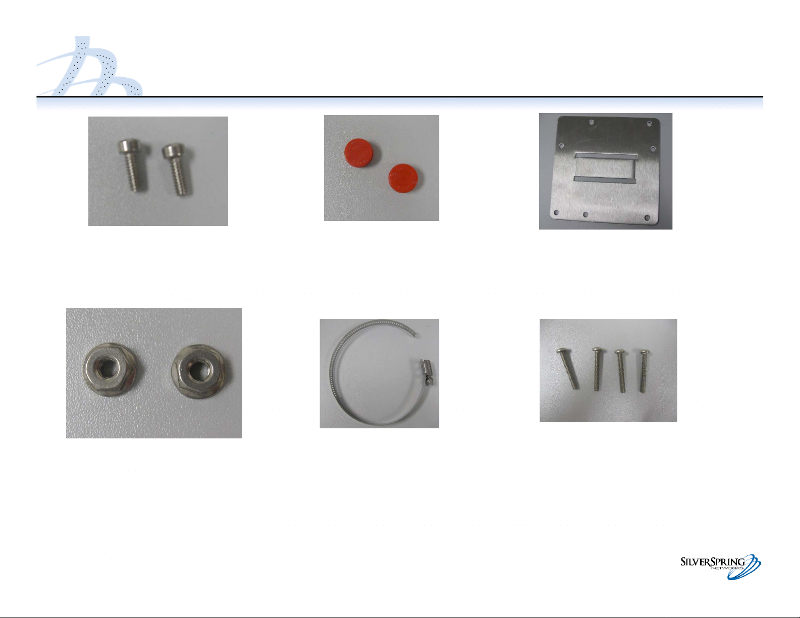
Components
Screws 10-24 x 1/2 Tamper Seals
Flanged nut 10-24
Pipe clamp
Mounting Plate
Cover screws, 6-32 x 1”
© 2010 Silver Spring Networks | Company Confidential
6
Page 7

Assembly Drawing (Single Channel Rotary and Turbine Meter IMU)
© 2010 Silver Spring Networks | Company Confidential
7
Page 8

Assembly Drawing (Single Channel Rotary and Turbine Meter IMU)
© 2010 Silver Spring Networks | Company Confidential
8
Page 9

Inspect the Pulser Cable
• Inspect the end of the pulser
cable that will connect to the
IMU.
– There should be three wires
exiting the outside insulation.
– The red and black wires are
insulated.
– The 3
rd
wire is bare coming out
of outside insulation, with a
white sleeve on the end.
• If needed, trim the pulser wires
so the conductor is flush with
the insulation and sleeve.
Insert photo
Pulser installation onto the gas meter is not
covered here. Refer to the pulser
manufacturer’s installation instructions.
© 2010 Silver Spring Networks | Company Confidential
9
Page 10

• Verify that the IMU has 3 wires
Inspect the IMU
• Verify that the enclosure is not
cracked and that the MAC Address
label is present
• Verify that the
battery
connectors are
undamaged.
• Verify
If the IMU is damaged, return it to your supervisor and get a replacement.
© 2010 Silver Spring Networks | Company Confidential
10
Page 11

Connect the Pulser to the IMU
•Thread the pulser cable through
the cable seal connector.
•Thread the pulser cable through
the tie wrap.
•Connect the 3 cables with the gel
splices.
– Do not strip the insulation from
the wires.
– Insert the wire pair (red and red,
black and black, white and
white) to be connected into a gel
splice; push all the way forward.
– Close the gel splice by squeezing
the gel splice with pliers.
– Repeat for the 3 pairs of wires
© 2010 Silver Spring Networks | Company Confidential
11
Page 12

Connect the Pulser to the IMU
• Make sure the 3 gel splices are to
the right of the cable tie.
• Tighten the cable tie. This
provides extra strain relief for the
cable.
• Trim the cable tie.
• Leave 1” of cable slack inside the
IMU, and pull the rest of the
cable out of the cable seal
connector.
• Tighten the cable seal connector.
© 2010 Silver Spring Networks | Company Confidential
12
Page 13

Connect the Battery Cable Connector
•Connect the battery cable to the
IMU cable. The connectors are
keyed; you will not need to force
them together.
•Put the battery inside the battery
compartment as shown.
– The connector fits underneath
the battery.
– The flat part of the battery
should be next to the inside wall.
© 2010 Silver Spring Networks | Company Confidential
13
Page 14

Program the IMU for Field Use
• Slowly pass the service magnet
once (for 2 to 5 seconds) over the
top of the IMU.
• Watch for the light-emitting diode
(LED) to flash on the lower left
corner of the IMU circuit board
– If you don’t see the LED flash,
make sure the battery cable
connections are made.
– If you still don’t see the LED flash
after checking that all the battery
connections are made and reswiping the magnet, return the IMU
to your supervisor. Insert photo
• Configure the IMU with the
programming tool.
Configuration is a separate document).
© 2010 Silver Spring Networks | Company Confidential
(Field
14
Page 15

Inspect the Gasket and Fasten the Cover
• Re-inspect the gasket to
ensure it seals the area
between the enclosure and
cover. Insert photo
• Fasten the cover to the
enclosure with the 4 cover
screws.
– The Silver Spring logo faces
up
– Torque the cover screws to
xxx
• Use a nut driver to push two
tamper seals into the
openings on the IMU cover.
© 2010 Silver Spring Networks | Company Confidential
15
Page 16

Attach the IMU Enclosure to the Mounting Plate
• Determine where you want to
install the IMU. This will
determine if the plate should
attach to the pipe horizontally or
vertically.
The photos here show a vertical attachment.
• Attach the IMU enclosure to the
mounting plate with the 2 screws
and 2 flanged nuts.
• Torque the screws to…
© 2010 Silver Spring Networks | Company Confidential
16
Page 17

Attach the IMU and Mounting Plate to the Pipe
• Guide the metal clamp through
the slot in the mounting plate.
• Wrap the metal clamp around
the pipe.
• Tighten the metal clamp around
the pipe by torquing the screw to
12-20 in lb.
© 2010 Silver Spring Networks | Company Confidential
17
 Loading...