

Page 1
Itron Mobile Radio User Guide
14 May 2019 TDC-1719-002 1
Page 2

Itron Mobile Radio User Guide
Itron Mobile Radio User Guide
14 May 2019
TDC-1719-002
Copyright © 2019 Itron, Inc. All rights reserved.
Confidentiality Notice
Confidential Information of Itron®, Inc., provided under nondisclosure obligations. The information
contained herein is proprietary and confidential and is being provided subject to the condition that (i) it
be held in confidence except to the extent required otherwise by law and (ii) it will be used only for the
purposes described herein. Any third party that is given access to this information shall be similarly
bound in writing.
Trademark Notice
Itron is a registered trademark of Itron, Inc.
All other product names and logos in this documentation are used for identification purposes only and
may be trademarks or registered trademarks of their respective companies.
For more information about Itron or Itron products, go to www.itron.com.
If you have questions or comments about a software or hardware product, contact Itron Technical
Support Services.
Contact
Email: support@itron.com
Itron Access: https://support.itron.com
Telephone Itron Technical Support North America: 1-877-487-6602
For technical support contact information by region, go to www.itron.com and select your country
and language.
14 May 2019
TDC-1719-002
2
Page 3

Itron Mobile Radio User Guide
Table of Contents
Table of Contents 3
Itron Mobile Radio compliance 5
1. Introduction 1
Feature List 1
Related Documents List 1
2. About Your Itron Mobile Radio 3
Itron Mobile Radio Parts List 3
3. Daily Operation 5
Charging the Portable IMR Battery 5
Charging the Mobile IMR-XA or IMR-FT Battery 5
Turning the Radio On or Off 6
4. LED Status Indicators 7
Power Indicator LED Table 7
Comm Indicator LED Table 8
5. Communication Ports 9
6. Carrying the Portable Itron Mobile Radio 10
7. Installing the IMR-XA and IMR-FT 11
IMR-XA / IMR-FT Antenna Specifications 11
Installing the Antenna 12
Selecting an Antenna Location on the Vehicle 12
Installing the Permanent Antenna Mounting Base 13
Installing the Magnetic Antenna Mounting Base 13
Installing the DC Power Cable 14
Power Cable Routing--All Installations 15
Power Cable Installation--Removable 15
Power Cable Installation--Permanent 15
Installing the Mounting Jacket in the Vehicle 16
Installing on a Seat Belt 16
14 May 2019
TDC-1719-002
3
Page 4

Itron Mobile Radio User Guide
Installing on a Partition 16
Installing on a Pedestal 17
Removing the IMR-XA from the Mounting Jacket 18
8. Maintaining your Itron Mobile Radio 19
Cleaning the Radio Case 19
Installing a Replacement Battery 20
Servicing the IMR-XA Charge Base 20
Removing the IMR-XA Charge Base 21
Replacing the Charge Base Antenna Cable 21
Servicing the IMR-XA External Antenna 22
Inspecting the Antenna Connectors and Cables 22
Inspecting the Antenna Base and Whip 23
Cleaning the Antenna 23
Replacing the Antenna Gasket 24
Replacing the Antenna Cable 24
9. Storing Your Radio 25
10. Battery Basics 26
Battery Best Practices List 26
11. Safety 28
AC Power Adapter 28
12. Troubleshooting 29
Issue and Solution Table 29
Radio Readings Tips 30
13. Optimizing Bluetooth® Performance 31
Pairing Bluetooth for Itron Mobile for FCS Users 31
Pairing Bluetooth in Windows 31
To Pair Bluetooth in Windows 31
14. Itron Mobile Radio Capabilities and Limitations 34
14 May 2019
TDC-1719-002
4
Page 5
Itron Mobile Radio User Guide
Itron Mobile Radio compliance
Equipment description
Itron Mobile Radio
PMN: IMR PMN: IMR2 PMN: IMR-XA/IMR-FT
FCC ID: EO9IMRA FCC ID: EO9IMRB FCC ID: EO9IMRB
IC: 864A-IMRA IC:864A-IMRB IC: 864A-IMRB
HVIN: IMRA HVIN: IMRB-INT HVIN: IMRB-EXT
FCC USA intentional radiator compliance statement
This device complies with Part 15 of the FCC Rules. Operation is subject to the following two
conditions:
1. This device may not cause harmful interference, and
2. This device must accept any interference received, including interference that may cause
undesired operation.
FCC USA un-intentional radiator compliance statement
This equipment has been tested and found to comply with the limits for a Class B digital
device, pursuant to part 15 of the FCC Rules. These limits are designed to provide reasonable protection against harmful interference in a residential installation. This equipment
generates, uses, and can radiate radio frequency energy and, if not installed and used in
accordance with the instructions, may cause harmful interference to radio communications.
However, there is no guarantee that interference will not occur in a particular installation.
If this equipment does cause harmful interference to radio or television reception, which can
be determined by turning the equipment off and on, the user is encouraged to try to correct
the interference by one or more of the following measures:
Reorient or relocate the receiving antenna.
Increase the separation between the equipment and receiver.
Connect the equipment into an outlet on a circuit different from that to which the receiver is
connected.
Consult the dealer or an experienced radio or TV technician for help.
ISED Canada compliance statements
14 May 2019
Compliance Statement Canada Déclaration de Conformité
Under Innovation, Science and Economic Devel- Conformément à la réglementation d'Industrie
TDC-1719-002
5
Page 6

Itron Mobile Radio User Guide
Compliance Statement Canada Déclaration de Conformité
opment Canada (ISED) regulations, this radio trans-
mitter may only operate using an antenna of a type
and maximum (or lesser) gain approved for the trans-
mitter by Innovation, Science and Economic Devel-
opment Canada. To reduce potential radio
interference to other users, the antenna type and its
gain should be so chosen that the equivalent iso-
tropically radiated power (e.i.r.p.) is not more than
that necessary for successful communication.
This device complies with Innovation, Science and
Economic Development Canada license-exempt
RSS standard(s). Operation is subject to the fol-
lowing two conditions: (1) this device may not cause
interference, and (2) this device must accept any
interference, including interference that may cause
undesired operation of the device.
Canada, le présent émetteur radio peut fonctionner
avec une antenne d'un type et d'un gain maximal (ou
inférieur) approuvé pour l'émetteur par Industrie
Canada. Dans le but de réduire les risques de brouil-
lage radioélectrique à l'intention des autres util-
isateurs, il faut choisir le type d'antenne et son gain
de sorte que la puissance isotrope rayonnée équi-
valente (p.i.r.e.) ne dépasse pas l'intensité néces-
saire à l'établissement d'une communication
satisfaisante.
Le présent appareil est conforme aux CNR
d'Industrie Canada applicables aux appareils radio
exempts de licence. L'exploitation est autorisée aux
deux conditions suivantes : (1) l'appareil ne doit pas
produire de brouillage, et (2) l'utilisateur de l'appareil
doit accepter tout brouillage radio électrique subi,
même si le brouillage est susceptible d'en com-
promettre le fonctionnement.
RF Exposure (FCC/ISED)
Compliance Statement Canada Déclaration de Conformité
This equipment complies with radiation exposure
limits set forth for an uncontrolled environment.
The IMRB-EXT vehicle antenna(s) must be
installed to provide a separation distance of at
least 20 cm from all persons and must not be colocated or operating in conjunction with any other
antenna or transmitter.
Cet équipement est conforme à l'exposition au rayonnement limites définies pour un environnement
non contrôlé. L'antenne du véhicule IMRB-EXT doit
être installée de manière à prévoir une distance de
séparation d'au moins 20 cm de toutes les personnes et ne doit pas être colocalisé ou fonctionnant en conjonction avec toute autre antenne
ou émetteur.
Electromagnetic compatibility
Caution: ELECTROMAGNETIC COMPATIBILITY
Use only approved accessories with this equipment. In general all cables must be high quality, shielded, and correctly terminated. Unapproved modifications or operation beyond or in
conflict with these instructions for use, may void authorization by the authorities to operate
the equipment.
Important: Changes or modifications to the device or its antenna not expressly approved by the
party responsible for compliance could void the user’s authority to operate the device.
14 May 2019
Transportation classification
TDC-1719-002
6
Page 7

Itron Mobile Radio User Guide
The Federal Aviation Administration prohibits operating transmitters and receivers on all
commercial aircraft. When powered, Itron Mobile Radios are considered operating transmitters and receivers and cannot be shipped by air with the battery installed. To ship by air,
remove the battery and follow li-ion shipping regulations.
Specific absorption rate data
The IMRA and IMRB devices meet the government's requirements for exposure to radio
waves. Your Itron Mobile Radio has a radio transmitter and receiver. It is designed and manufactured not to exceed limits for exposure to radio frequency (RF) energy set by the Federal
Communications Commission (FCC) of the U.S. government and by the Canadian regulatory authorities. These limits are part of comprehensive guidelines and establish permitted levels of RF energy for the general population. The guidelines are based on
standards that were developed by independent scientific organizations through periodic and
thorough evaluation of scientific studies. The standards include a substantial safety margin
designed to assure the safety of all persons, regardless of age or health.
The exposure standard for wireless mobile and/or portable devices employs a unit of measurement known as the specific absorption rate, or SAR. The SAR limit set by the FCC and
by the Canadian regulatory authorities is 1.6 W/kg1. Tests for SAR are conducted using
standard operating positions accepted by the FCC and by Innovation, Science and Economic Development Canada with the radio transmitting at its highest certified power level in
all test frequency bands. Although the SAR is determined at the highest certified power
level, the actual SAR level of the radio while operating can be well below the maximum level.
This is because the Radio is designed to operate at multiple power levels, depending on the
needs of the customer.
Before an Itron Mobile Radio is available for sale to the public in the U.S. and Canada, it
must be tested and certified to the FCC and Innovation, Science and Economic Development Canada that it does not exceed the limit established by each government for safe
exposure. The tests are performed in positions and locations (for example, worn on the
body) and reported to the FCC and made available for review by Innovation, Science and
Economic Development Canada. The highest SAR value for this Itron Mobile Radio, model
IMR when tested for use when worn on the body as described in the user’s guide is 0.25
W/kg (IMRA) and 1.2 W/kg (IMRB). While there may be differences between the SAR levels
of various Itron Mobile Radio models and at various positions, they all meet the government
requirements for safe exposure. Please note that improvements to this product model could
cause differences in the SAR value for later products; and in all cases, products are
designed to be within the guidelines.
1
In the United States and Canada, the SAR limit for wireless mobile and/or portable devices used by the
public is 1.6 W per kilogram averaged over 1 g of tissue. The standard incorporates a substantial margin of
safety to get additional protection for the public and to account for any variations in measurements.
14 May 2019
TDC-1719-002
7
Page 8
Itron Mobile Radio User Guide
The Australian version of this device has been tested and found to be compliant to Australian
standards. It is identified with the RCM mark on the label.
Warning: Warning: Use this device only in a manner consistent with
the Itron Mobile Radio User Guide
14 May 2019
TDC-1719-002
8
Page 9
1. Introduction
This document details the features and functions of the Itron Mobile Radio and provides
information relating to its use and maintenance.
The Itron Mobile Radio is available in several models: the original handheld, portable Itron
Mobile Radio (IMR) with a built-in antenna and the new External Antenna and Field Tools
versions of the IMR (IMR-XA, IMR-FT) that are mounted in a vehicle for mobile drive-by endpoint reading and field tool operations, respectively.
All IMR models share many of the same features and operations. Those common to all
models will be described and attributed to the IMR in a generic sense. Key differences in
models will be described and attributed to either the portable IMR or the mobile IMR-XA and
IMR-FT.
Feature List
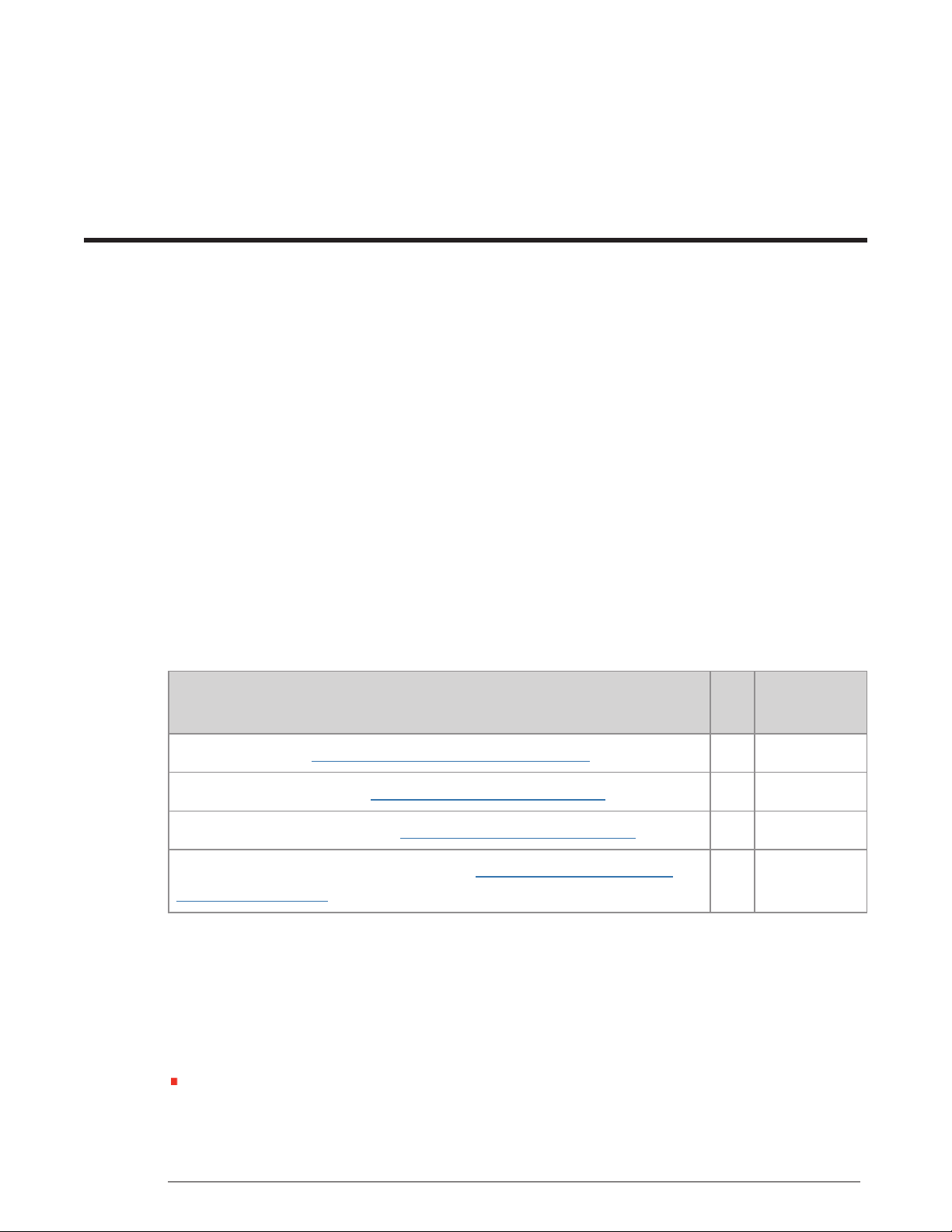
Each Itron Mobile Radio is equipped with the following features.
Feature IMR IMR-XA /
Power button. See Turning the Radio On or Off on page6. X X
LED status indicators. See LED Status Indicators on page7. X X
USB communication port. See Communication Ports on page9. X X
Bluetooth wireless communications. See Optimizing Bluetooth® Per-
formance on page31
Related Documents List
For more information about the Itron Mobile Radio and the Itron Mobile for FCS app. See the
most current versions of the following documents.
Itron Mobile for FCS User Guide (TDC-1717-xxx) The Itron Mobile Radio is designed for use
with handheld and laptop computers running the Itron Mobile for FCS app.
IMR-FT
X X
14 May 2019 TDC-1719-002 1
Page 10

Itron Mobile Radio User Guide 1. Introduction
Itron Mobile Radio Quick Reference Guide (TDC-1720-xxx)
Itron Mobile Radio Compliance Statement (TDC-1722-xxx)
14 May 2019 TDC-1719-002 2
Page 11
2. About Your Itron Mobile Radio
When you unpack your radio, make sure you have all of the components listed in the following tables. If any are missing, contact Itron Support Services immediately.
For the portable IMR, an optional Radio Carrying Kit is available for order separately. The
Radio Carrying Kit contains a belt clip and a shoulder harness.
Itron Mobile Radio Parts List
The following tables describe all the parts that are included with your Itron Mobile Radio.
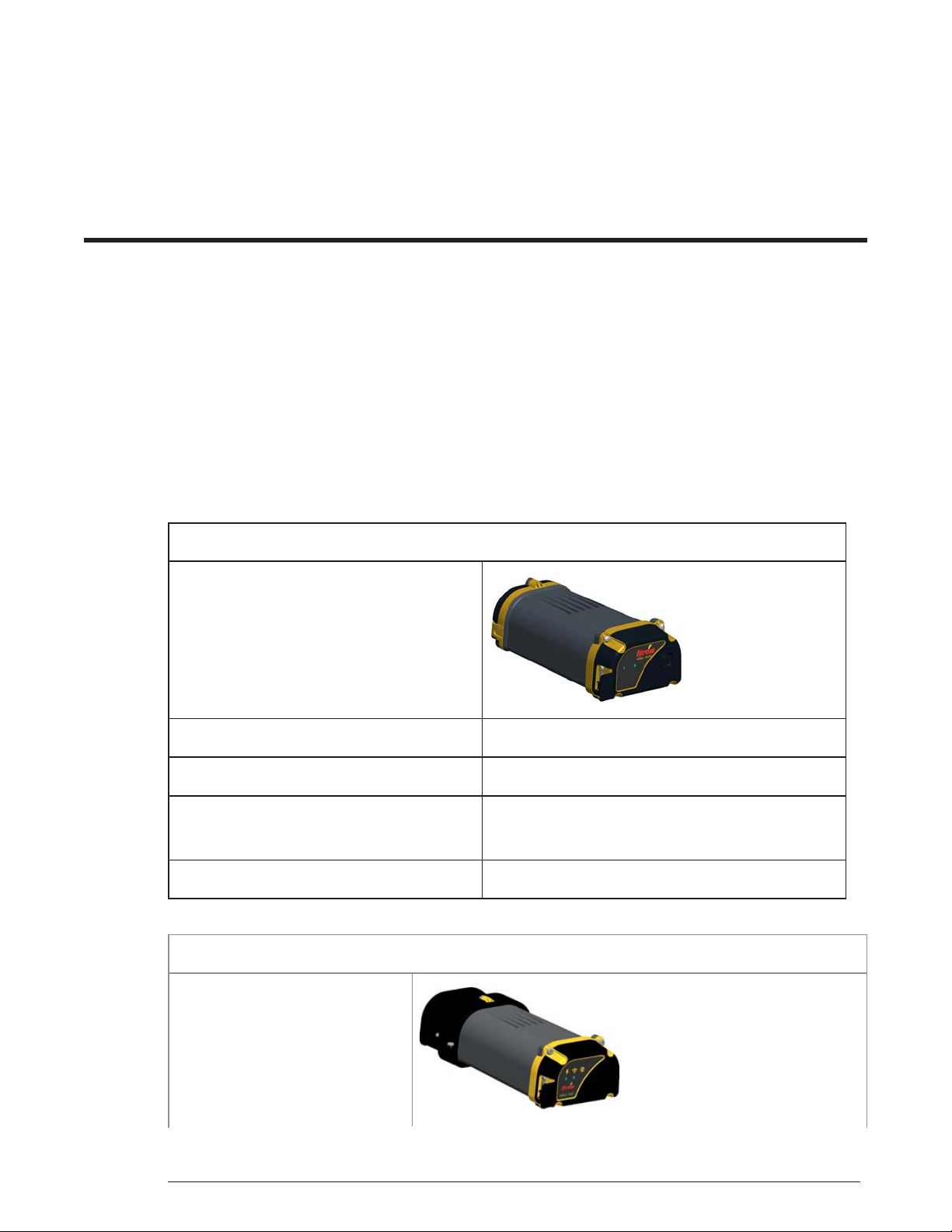
The portable Itron Mobile Radio comes with the following items.
Itron Mobile Radio with built-in antenna
AC power adapter AC wall plug with USB type A port.
Communication and charging cable USB cable.
Documentation
(Optional) Belt clip and shoulder harness Included if the optional Radio Carrying Kit is ordered.
The mobile IMR-XA and IMR-FT come with the following items.
Itron Mobile Radio with
attached charge base
Itron Mobile Radio Quick Reference Guide
Itron Mobile Radio Compliance Statement
14 May 2019 TDC-1719-002 3
Page 12

Itron Mobile Radio User Guide 2. About Your Itron Mobile Radio
External antenna 26.5 inch antenna whip
Antenna vehicle mount with
cable
Antenna mount with attached cable.
Available as a permanent mount with a 17-foot
cable or a magnetic mount with a 12-foot cable.
IMR-XA mounting jacket with
adapter plate
Securely holds the IMR-XA and mounts to a seat belt, partition, or
pedestal.
DC power cable Two-meter cable with 12V DC vehicle accessory plug.
Communication and charging
Two-meter USB cable with right-angle micro USB plug.
cable
Documentation
Itron Mobile Radio Quick Reference Guide
Itron Mobile Radio Compliance Statement
14 May 2019 TDC-1719-002 4
Page 13

3. Daily Operation
Inspect the radio for broken, loose, or missing parts and fasteners, taking corrective action as
required.
Ensure that the IMR-XA external whip is securely connected to its mounting base, and the
mounting base is securely attached to the vehicle.
Make sure the radio is operated and stored within the recommended temperature range.
Operating temperature: -5° F to 140° F (-15° C to 50° C)
Storage temperature: -40° F to 158° F (-40° C to 70° C)
Cold temperature extremes may result in reduced available energy from the battery
pack. This energy is recoverable as the battery pack warms to 68° F (20° C).
Do not subject the radio to extreme temperatures, such as leaving it in a vehicle in bright
sunlight. Extended exposure to warm temperature extremes can result in permanent
reduction in available energy from the battery pack.
Exit all external applications at the end of each work day and power the radio off. This
ensures that all applications communicating with the radio have terminated their communication links and the IMR battery is not being discharged.
Charge the portable IMR battery nightly.
Charging the Portable IMR Battery
1. Plug the USB cable into the radio.
2. Plug the USB cable into a PC or an AC wall adaptor.
3. Allow the radio to charge for at least six hours before you use it or store it.
Charging the Mobile IMR-XA or IMR-FT Battery
1. Plug the vehicle DC power cable into the charge base.
2. Plug the DC power cable into the vehicle accessory adapter.
3. Allow the radio to charge for at least six hours before you use it or store it.
14 May 2019 TDC-1719-002 5
Page 14

Itron Mobile Radio User Guide 3. Daily Operation
Turning the Radio On or Off
Turn on while using battery power:
Press and hold the button for three seconds (until the Power LED turns green) to turn the
radio on.
Turn off while using battery power:
Press and hold the button for three seconds (until the Power LED turns white) to to turn
the radio off.
Turn on while using external power:
The radio is always on when using external power.
When the radio is using external power (connected to an energy source with the USB
cable or the IMR-XA / IMR-FT connected to 12V DC vehicle power cable) pressing the
button turns the power LED green until the button is released, but it does not turn the
radio off. The IMR-XA and IMR-FT radios remain on as long as they are being powered
by the vehicle.
To preserve battery energy, a radio not connected to external power automatically shuts
down after a period of inactivity. If this occurs, turn the unit on as described above.
14 May 2019 TDC-1719-002 6
Page 15

4. LED Status Indicators
Two multi-color LED status indicators are located on the top of the radio. These indicators
are labeled with a power icon and a communication icon . The color and illumination of
the LED lights provide feedback about the Itron Mobile Radio's status.
The LED lights have two patterns for displaying different states.
Solid. LED is on continuously.
Flash. LED turns off and on at a constant interval.
Power Indicator LED Table
The following table describes the LED colors and patterns for the most common radio conditions.
Power indicator
Solid Flash
green
yellow
red
white
Initializing
Button pressed
Charged
N/A
Charging
Error: Battery
Turning on
Note: When an IMR with a fully discharged battery is connected to
power via its USB cable, it may display a solid white LED or the LED
may randomly turn on and then off again. This is normal behavior while a
fully discharged battery is charging to a minimum voltage, at which time it
should follow the states shown in the Power indicator LED table. Wait
green
Battery more than 50%
Battery more than 20%
yellow
Battery less than 20%
red
Error: General
white
14 May 2019 TDC-1719-002 7
Page 16

Itron Mobile Radio User Guide 4. LED Status Indicators
several hours while the battery charges and you should eventually see
the power LED turn solid red, indicating it is charging, and finally solid
green, indicating that it is fully charged and ready for use. If the white
LED never turns off while the IMR is connected to power, the battery is
likely bad and must be replaced. This will need to be done approximately
every 300 to 500 charge cycles. See Installing a Replacement Bat-
tery on page20.
Comm Indicator LED Table
The following table describes the LED colors and patterns for the most common radio conditions.
Comm indicator
Solid Flash
USB connected
green
blue
Note The application connected to the radio may assign a display pattern to the LEDs that is not
described in these tables.
Bluetooth® connected
white
blue
Error
Bluetooth low energy connected
14 May 2019 TDC-1719-002 8
Page 17

5. Communication Ports
The Itron Mobile Radio has one micro USB communication port under a protective rubber
flap on the side of the radio near the top.
Note: The USB cable supplied with the IMR-XA and IMR-FT has a
down-angle micro USB connector to facilitate proper cable management
with the mounting jacket. Using a cable with a straight or up-angle connector will put unnecessary stress on the radio USB port and may, over
time, lead to a poor cable connection.
In addition, the radio is equipped with an internal port for wireless Bluetooth®communications. If communication is in place through Bluetooth, attaching the USB cable only
provides power. Communication may occur through Bluetooth while charging with the USB.
Note: Some Windows 7 or Windows 8 users may experience difficulty
connecting to the device via USB or may see a prompt to install an
updated Texas Instruments driver for the device. Download and install
the Itron Mobile Radio USB driver available from Itron Access at
https://access.itron.com/ (available for registered users).
14 May 2019 TDC-1719-002 9
Page 18

6. Carrying the Portable Itron Mobile Radio
The portable Itron Mobile Radio’s optional shoulder harness and belt clip provide convenient,
hands-free ways to carry the radio while installing, reading, and maintaining meters and endpoints. The shoulder harness and belt clip let you wear the radio comfortably while walking or
driving.
As a safety feature, the clips are designed to break away if the radio snags or becomes
caught, releasing the wearer and reducing the likelihood of injury.
The radio may also be carried in a pocket, backpack, or bag.
The radio is water resistant.
Note: If you are carrying the radio, make sure the side with the ridges is
facing away from your body, conductive materials, or anything else
which may shield the radio signal.
14 May 2019 TDC-1719-002 10
Page 19

7. Installing the IMR-XA and IMR-FT
Refer to the following procedures for guidance on installing your IMR-XA or IMR-FT.
Installing the Antenna on the next page
Power Cable Routing--All Installations on page15
Installing the Mounting Jacket in the Vehicle on page16
IMR-XA / IMR-FT Antenna Specifications
This section provides the specifications for the IMR-XA / IMR-FT external vehicle antenna.
Caution: The IMR-XA / IMR-FT system is designed to operate with the
antenna listed here. Antennas not listed here are strictly prohibited for
use with this IMR-XA / IMR-FT system. The required antenna impedance is 50 ohms.
Innovation, Science, and Economic Development Canada (ISED) Conformity
This radio transmitter, 864A-IMRB, has been
approved by Innovation, Science and Economic Development Canada to operate with
the antenna types listed below, with the maximum permissible gain indicated. Antenna
types not included in this list that have a gain
greater than the maximum gain indicated for
any type listed are strictly prohibited for use
with this device.
Specification 915 MHz Mobile Antenna
Itron part number MSE-0122-002
Frequency range 908-958 MHz
Maximum gain 5 dBi
Polarization Vertical omni-directional
Cet émetteur radio, 864A-IMRB, a été approuvé
par Innovation, Sciences et Développement
économique Canada pour fonctionner avec les
types d’antennes énumérés ci-dessous, avec le
gain maximal admissible indiqué. Les types
d'antenne non inclus dans cette liste et dont le
gain est supérieur au gain maximal indiqué pour
l'un des types répertoriés ne sont strictement pas
autorisés pour une utilisation avec cet appareil.
14 May 2019 TDC-1719-002 11
Page 20

Itron Mobile Radio User Guide 7. Installing the IMR-XA and IMR-FT
Specification 915 MHz Mobile Antenna
Impedence 50 ohms
Termination 1-1/8-inch 18 thread mount
Overall dimensions 26.5-inch length x 1.43-inch diameter
Installing the Antenna
Installation of the antenna includes the following tasks. Perform the tasks in the order shown
in the following list.
1. Selecting an Antenna Location on the Vehicle below
2. Installing the Permanent Antenna Mounting Base on the next page
3. Installing the Magnetic Antenna Mounting Base on the next page
Selecting an Antenna Location on the Vehicle
The antenna remains installed on the vehicle. The manufacturer's instructions, which ship
with the antenna components, are summarized in the following procedures. Itron recommends consulting the antenna manufacturer's instructions in addition to this guide.
Note: Do not trim, shorten, or secure any cabling until you are confident
of its routing.
Location selection criteria include the following.
Access from inside the vehicle to the exterior antenna mounting location is usually required.
If the vehicle has a headliner, remove nearby trim pieces or even a dome light to gain access
to the mounting location.
Install the antenna a minimum of 12 inches from any other antennas or metal structures on
the vehicle's roof that could disrupt communication with endpoints. 30 inches is recommended.
Select a location on the vehicle's roof that has as flat a surface as possible. The metal of the
roof must be 0.02 to 0.04 inches thick.
The location should be no more than one inch deep and at least 2.5 inches in diameter to
properly secure the antenna base.
To meet RF exposure safety requirements, the antenna must be installed a minimum of 21.7
inches (55 centimeters) from where any bystanders may be located.
14 May 2019 TDC-1719-002 12
Page 21

Itron Mobile Radio User Guide 7. Installing the IMR-XA and IMR-FT
The diameter of the ground plane at the antenna base should be at least three feet for best
performance. Ideally, the ground plane should be a minimum of three times the wavelength
being received. For example, a 900 MHz signal, having a 13 inch wavelength, should have a
ground plane of 39 inches.
Installing the Permanent Antenna Mounting Base
The permanent mount antenna base can be installed on the outside of the roof or trunk of the
vehicle.
1. Drill or cut a ¾-inch diameter hole in the vehicle where the antenna is to be located.
2. Carefully feed the connector and coaxial cable through the hole from the top side and thread
it out of the headliner near the IMR-XA mounting location.
3. Insert the rest of the cable and the lower tabs of the mount body through the hole from the
top.
4. Center the mount body in the hole.
5. Ensure that the rubber O-ring is pressed into the groove in the brass nut and thread the nut
onto the mount body.
6. Finger-tighten the nut and then use a wrench to tighten the nut until the O-ring is compressed. If the mount body spins while you are tightening the nut, use a spanner wrench
applied to the two holes on the top of the mount body to hold it still.
7. Clean the surface of the vehicle around the antenna mount body.
8. Ensure that the gasket is properly set in the antenna base.
9. Thread the antenna base onto the mount body, making sure not to cross-thread the mount.
10. Continue tightening the antenna base until it seats to the vehicle.
11. Complete the cable routing to the IMR-XA in the vehicle and secure the cable.
Installing the Magnetic Antenna Mounting Base
The magnetic mount antenna base can be installed temporarily on the metal roof or trunk of
the vehicle and then removed as desired.
1. Ensure that the gasket is properly set in the antenna base.
2. Pre-assemble the antenna to the magnetic mount by threading the antenna base onto the
mount body, making sure not to cross-thread the mount.
3. Continue tightening the antenna base until it seats to the mount.
4. Before mounting the magnetic base on the vehicle, clean both the magnet surface and the
mounting surface.
14 May 2019 TDC-1719-002 13
Page 22

Itron Mobile Radio User Guide 7. Installing the IMR-XA and IMR-FT
5. Place the antenna base on the vehicle where it is flat and ensure that the entire magnet is
making secure contact with the vehicle.
6. Route the antenna cable through an open window or door and secure it in such a way that it
will not be accidentally pinched and kinked or damaged. Complete the cable routing to the
IMR-XA in the vehicle and secure the cable.
Note: If the vehicle door must be opened with the cable in place,
make sure to leave enough slack in the cable so as not to pull on the
IMR-XA when the door opens.
7. When removing the antenna, hold the antenna at the bottom of its base and tilt the antenna
to release the magnetic force. Do not pull on the coaxial cable to release the magnetic force
and do not drag the magnet across the surface of the vehicle.
Installing the DC Power Cable
The DC power supply cable connects to the vehicle's electrical system so you can easily connect and disconnect power for the IMR-XA or IMR-FT. The DC power cable is shipped with
a vehicle accessory (12V) adapter attached so the cable and the IMR can be easily moved
between different vehicles. If preferred, the accessory adapter may be cut off and the unterminated end of the cable hardwired permanently to the vehicle fuse block or other 12V DC
power source, so the cable remains in the vehicle. The IMR is still removable.
The following illustrations show the vehicle accessory adapter and the unterminated end of
the power supply cable with the accessory adapter removed. Notice the polarity and marking
of the power supply cable wires.
Wire Description
Black, no writing Positive
Black, with writing Negative
14 May 2019 TDC-1719-002 14
Page 23

Itron Mobile Radio User Guide 7. Installing the IMR-XA and IMR-FT
Power Cable Routing--All Installations
1. Once the mounting location of the IMR is known, select a location in the vehicle for the IMR
connector end of the cable so that it reaches the Itron Mobile Radio power jack without putting stress on the cable or radio.
Route the vehicle accessory adapter end of the cable to the desired voltage and ground-
2.
ing sites in the vehicle, typically either an accessory jack for a removable installation or
the fuse block for a permanent installation. Leave enough slack in the cable to work with
it and so it is not stressed during use.
Caution: Do not route the cable where it can become abraded or damaged, such as under
the carpet in high traffic areas, over sharp edges, near hot engine components, near brake or
clutch linkages, or where it can be exposed to oil or other corrosive liquids.
Power Cable Installation--Removable
To temporarily install the DC power cable using the vehicle accessory adapter, route the
adapter end of the cable to a 12V DC accessory jack and plug the adapter in securely. To
remove the adapter, grip the adapter body and pull; do not pull on the cable.
Note: Some accessory jacks are unswitched and have power always
on, and some are switched by the vehicle ignition key. Determine which
accessory jacks you have and which you intend to use before routing the
cable.
Power Cable Installation--Permanent
1. To permanently hard wire the DC power cable, first remove the vehicle accessory adapter
from the DC power cable by cutting the cable where it connects to the adapter. Dispose of
the adapter properly.
2. Route the unterminated end of the cable to the fuse block or other 12V DC source. If necessary, trim the cable wires to a suitable length and strip the insulation from the wires according
to the requirements of the installation.
3. Connect the plain black wire (without white writing) to a spare fuse location in the vehicle
fuse block that has a rating of five amps. If no spare fuse location is available, a five amp
inline fuse must be spliced into the positive side of the cable. Then the wire can be connected
to either a switched or unswitched 12V DC power source, depending on the user requirements.
Caution: When hard wiring the DC power cable to the vehicle a five ampere fused con-
nection is required.
4. Connect the black wire with white writing directly to the vehicle's chassis ground.
14 May 2019 TDC-1719-002 15
Page 24

Itron Mobile Radio User Guide 7. Installing the IMR-XA and IMR-FT
Installing the Mounting Jacket in the Vehicle
The IMR Mounting Jacket can be installed in a vehicle in several ways. The following procedures describe three of the possible configurations.
Warning: The primary consideration when installing the IMR Mounting
Jacket is that the IMR be securely attached to the vehicle. Failure to do
so could lead to injury or death from unsecured components during a
sudden stop, rollover, or collision.
Installing on a Seat Belt
1. Put the IMR in the mounting jacket and engage the plastic side release buckles.
2. Ensure the IMR is securely encased in the mounting jacket and tighten the straps if necessary.
3. Attach the mounting jacket to the seatbelt.
4. Plug in the micro-USB and secure it with the Velcro strap as shown in the following illustration.
5. Attach the power cable and antenna cable to their connectors on the charge base.
Installing on a Partition
1. Attach the mounting plate to the mounting jacket in the orientation most useful for your purpose.
2. Use cable ties or some other secure fastener to attach the mounting jacket to the vehicle partition.
3. Put the IMR in the mounting jacket and engage the plastic side release buckles.
14 May 2019 TDC-1719-002 16
Page 25

Itron Mobile Radio User Guide 7. Installing the IMR-XA and IMR-FT
4. Plug in the micro-USB and secure it with the Velcro strap as shown in the following illustration.
5. Attach the power cable and antenna cable to their connectors on the charge base.
Installing on a Pedestal
1. Attach the mounting plate to the mounting jacket in the orientation most useful for your purpose.
2. Use cable ties or some other secure fastener to attach the mounting jacket to the pedestal.
3. Put the IMR in the mounting jacket and engage the plastic side release buckles.
4. Plug in the micro-USB and secure it with the Velcro strap as shown in the following illustration.
5. Attach the power cable and antenna cable to their connectors on the charge base.
14 May 2019 TDC-1719-002 17
Page 26

Itron Mobile Radio User Guide 7. Installing the IMR-XA and IMR-FT
Removing the IMR-XA from the Mounting Jacket
1. Unplug the power cable and antenna cable.
2. Unplug the micro-USB and open the Velcro strap.
3. Disengage the plastic side release buckles on the mounting jacket and remove the IMR.
14 May 2019 TDC-1719-002 18
Page 27

8. Maintaining your Itron Mobile Radio
Your Itron Mobile Radio is rugged and water-resistant. However, you should take the following precautions to ensure that it gives you many years of reliable service.
Do not subject the radio to extreme temperatures, such as leaving it in a vehicle in bright sunlight. For more information, see Battery Best Practices List on page26.
Do not leave it in damp or dusty places.
Do not drop your radio or subject it to severe impacts.
Do not use products containing DEET near the Itron Mobile Radio. DEET will degrade the
radio's casing. DEET is a common ingredient in many insect repellents.
When installing or replacing the battery, make sure to follow the provided instructions to maintain water tightness.
Use the rubber flap to protect the radio’s USB port in dusty conditions.
Protect the antenna and power connectors on the IMR-XA charge base when the radio is
being installed, removed, or carried.
The IMR-XA charge base is not water resistant. Protect it from rain and moisture.
Ensure that the IMR-XA external antenna whip is securely connected to its mounting base.
Cleaning the Radio Case
1. Wipe the radio’s case with a damp cloth.
2. Use a soft-bristle brush to remove stubborn deposits.
Blow any water out of the connector and then leave the radio to drain and air-dry.
3.
Warning: Never use solvents of any kind on the case. Do not
expose it to temperatures above 140° F (50° C).
14 May 2019 TDC-1719-002 19
Page 28

Itron Mobile Radio User Guide 8. Maintaining your Itron Mobile Radio
Installing a Replacement Battery
1. Make sure the IMR is powered off and disconnected from other power sources.
Remove the battery compartment door.
2.
For the IMR-XA and IMR-FT you must first remove the charge base.
3. Insert the battery into the compartment.
Make sure the battery label is facing the ridges on the radio case.
Make sure the wires are along the same side as the connector.
Make sure the removal tab is facing out.
Caution: Do not pinch the battery wires when replacing the battery compartment cover.
4. Replace the battery compartment cover making sure the O-ring gasket is properly aligned for
water tightness.
5. Fasten the battery compartment cover in place with the provided screws.
Tighten the screws to ensure water tightness.
For the IMR-XA and IMR-FT, reinstall the charge base.
6. Plug the USB cable into the radio.
7. Plug the USB cable into a PC or an AC wall adapter, or connect the charge base cable to a
12V DC vehicle accessory adapter.
8. Allow the radio to charge for at least six hours.
Servicing the IMR-XA Charge Base
Itron recommends changing the antenna cable connection in the charge base every 500 disconnects. If you take the radio out of the vehicle at the end of each day, you will need to
replace the antenna cable connector about every 2.5 years.
14 May 2019 TDC-1719-002 20
Page 29

Itron Mobile Radio User Guide 8. Maintaining your Itron Mobile Radio
Note: Servicing the charge base should only be done indoors, at a clean
location, with the radio powered off. Safeguards against static electricity
should be observed.
Removing the IMR-XA Charge Base
Unscrew four screws to remove the charge base from the IMR-XA.
Replacing the Charge Base Antenna Cable
1. Remove the charge base from the IMR-XA.
2. Unscrew the small antenna cable connector (1) from the body of the IMR-XA.
14 May 2019 TDC-1719-002 21
Page 30

Itron Mobile Radio User Guide 8. Maintaining your Itron Mobile Radio
3. Unscrew the large antenna cable connector (2) from the bottom half of the charge base.
4. Install the new cable and screw the charge base back onto the radio.
Servicing the IMR-XA External Antenna
Regularly perform the following basic maintenance procedures to ensure optimal performance of your antenna.
Inspecting the Antenna Connectors and Cables below
Inspecting the Antenna Base and Whip on the next page
Cleaning the Antenna on the next page
Replacing the Antenna Gasket on page24
Replacing the Antenna Cable on page24
Inspecting the Antenna Connectors and Cables
The connections and cables to the radio typically experience the most wear. Many customers remove the radio on a daily basis. Removing and installing the connectors daily can
cause the cable and connector to begin separating. This is considered normal wear and tear.
The coax cables (used in the magnetic mount base) can be damaged if they are accidentally
pinched in a window or door jamb. Any damage to the coax cables or the connectors will lead
to decreased reading performance and transmitter failures due to high reflected power.
1. Create a regular maintenance schedule and inspect the following.
Coax cables
14 May 2019 TDC-1719-002 22
Page 31

Itron Mobile Radio User Guide 8. Maintaining your Itron Mobile Radio
Ensure the cable is not loose from the connector.
Inspect for hard kinks or bends in the cable, which can cause an electrical short.
Inspect for cuts or nicks in the cable.
Coax shield. Do not expose the inner cable shield at the connector or anywhere along
the cable.
Connector. The center pin of the connector should not be recessed or pushed in to the
connector housing.
2. Replace the entire antenna base if the cables or connectors are damaged. Contact Itron Support Services if you need assistance.
Inspecting the Antenna Base and Whip
The antenna whip is the radiating element that both transmits and receives the signals for the
system. The whip attaches to a base. The base is either mounted permanently through the
roof of the vehicle, or is a magnet mount. Moisture can build up between the base and the
whip. This moisture buildup leads to oxidation and corrosion which results in a loss of signal
quality. Evidence of moisture buildup (oxidation) on the antenna base threads is usually light
and hazy in appearance. The appearance of darker areas or spots indicates a more severe
condition which may lead to corrosion.
1. Create a maintenance schedule and look for the following.
Oxidation, corrosion, and dirt on the antenna base.
Oxidation, corrosion, and dirt on the whip.
Missing contact element in the whip.
Loose or damaged coax cable at the antenna base.
Missing or damaged O-ring gasket.
2. Use a good contact cleaner to clean the area if oxidation or corrosion is found. Follow with a
good conductive protectant. Contact Itron Support Services if you need assistance.
Cleaning the Antenna
Regular cleaning is recommended to maintain both the performance and the appearance of
your omni-directional RF antenna.
Clean the antenna in the same manner as your vehicle. Apply a quality car wax to the
antenna and base to help protect the finish and extend the life of the antenna.
Note: Before taking the vehicle through an automatic car wash that might damage the
antenna, Itron recommends that you remove the antenna whip from the permanent base or
the magnetic base and antenna from the vehicle.
14 May 2019 TDC-1719-002 23
Page 32

Itron Mobile Radio User Guide 8. Maintaining your Itron Mobile Radio
Replacing the Antenna Gasket
Inspect the gasket regularly to verify that it is intact, free from debris, and properly seals the
antenna and base. To maintain the integrity and performance of the antenna, Itron recommends that you replace the gasket located in the antenna base minimally once a year.
For more information about ordering the gasket, log onto Itron Access or contact Itron Support Services at 1.877.487.6602.
1. Turn the antenna counter-clockwise to remove it from the base.
2. Remove the gasket from the base.
3. Place a new gasket on the base and push it firmly into place.
4. Ensure that the gasket is level with the antenna base to prevent pinching when the antenna
is reconnected.
5. Reconnect the antenna to the base by turning it clockwise until it is firmly seated on the base.
Replacing the Antenna Cable
Itron recommends changing the antenna cable once a year. For more information about
ordering the antenna cable, log onto Itron Access or contact Itron Support Services at
1.877.487.6602.
1. Unscrew the antenna cable from the IMR-XA.
2. Unscrew the antenna cable from the antenna base.
3. Attach the new antenna cable to the antenna base.
4. Attach the antenna cable to the IMR-XA.
14 May 2019 TDC-1719-002 24
Page 33

9. Storing Your Radio
Your radio can be safely stored for six months or less with simple preparation.
Connect the Itron Mobile Radio to external power and allow the battery pack to fully charge.
For information about charging status, see LED Status Indicators on page7.
If you are storing the Itron Mobile Radio for an extended period of time, you should let it
remain charging or remove its battery.
Note: Remove the Itron Mobile Radio’s battery before storing the device for periods longer
than six months.
14 May 2019 TDC-1719-002 25
Page 34

10. Battery Basics
The Itron Mobile Radio uses a rechargeable lithium-ion (Li-Ion) battery pack as its main
power source whenever it is not receiving power externally.
Caution: Do not use any battery other than the Itron-recommended battery. Using another battery could damage the radio.
Warning: Danger: Risk of Explosion! There is a risk of explosion if
the battery is replaced by an incorrect battery type. Dispose of used batteries in accordance with local regulatory guidelines.
Warning: Danger: Il y a danger d’explosion s’il y a remplacement incorrect de la batterie. Remplacer uniquement avec une batterie du même
type ou d’un type equivalent recommandé par le constructeur. Mettre au
rebut les batteries usagées conformément aux instructions du fabricant.
Charge the radio's battery to 100 percent capacity before using it. Complete charging takes
about six hours. Charge the battery pack through the USB cable, which can draw power
from a computer, an AC wall adapter, or a 12V DC car adapter.
The Itron Mobile Radio meets the USB 2.0 Power Delivery standards. If the IMR does not
charge with your third-party device, validate that your device meets USB 2.0 standards. Not
all micro USB connectors meet the USB 2.0 standards.
Battery Best Practices List
Itron recommends the following practices to ensure long battery life.
Charge the radio at the end of each work day.
Check the charge status at the beginning of each work day.
Charge the radio at room temperature (68° F/20° C).
Charging is disabled below 32° F (0° C) and above 104° F (40° C) to protect the lithium-ion
batteries.
14 May 2019 TDC-1719-002 26
Page 35

Itron Mobile Radio User Guide 10. Battery Basics
In cold weather, keep the portable IMR inside your outer clothing. A cold battery will not
last all day even with full charge.
In hot weather, keep the radio out of direct sunlight. A hot battery's capacity is degraded
over time and eventually the battery will not last all day even with a full charge.
If an IMR has been left in a hot vehicle (above 104° F, 40° C), allow the vehicle and the
IMR to cool down before powering the IMR on.
Shallow or partial discharge and charge cycles are preferred, rather than allowing the battery pack to drain completely before recharging it.
Charging after a shallow or partial discharge does not degrade battery pack life or performance.
The lithium-ion IMR battery is good for approximately 300 to 500 charge cycles, depending
on its usage, before it must be replaced.
14 May 2019 TDC-1719-002 27
Page 36

11. Safety
Your Itron Mobile Radio is ergonomically designed for safe, comfortable use. However, as
with all equipment, you should follow good working practices while using it.
Minimize risk by following these guidelines.
Maintain good posture while using the radio. Keep your fingers and body relaxed whenever
possible.
Avoid keeping your muscles tense for long periods. Change tasks often to avoid prolonged
muscle strain. Support the radio while using it.
Take frequent short breaks. Use these breaks to exercise the muscles in your hands, arms,
shoulders, neck, and back.
Do not attempt to operate or adjust the IMR-XA or IMR-FT while driving.
AC Power Adapter
Follow these instructions to help ensure your safety and extend the life of the adapter.
Use the adapter indoors only.
Avoid spilling liquid on the adapter.
Do not connect it if it is damp.
Make sure ventilation around the adapter is not restricted while it is in use.
Itron recommends using only the AC adaptor supplied with your portable Itron Mobile Radio.
Inspect the AC adapter before use.
Do not use it if there are any signs of damage or deterioration.
Make sure the connector is firmly connected.
Avoid mechanical strain to cables and connectors.
In the event of overloading, the AC adapter is designed to be fail-safe and may stop functioning.
Do not try to use the AC adapter to power any other equipment.
Avoid use in dusty, damp, or contaminated environments.
14 May 2019 TDC-1719-002 28
Page 37

12. Troubleshooting
If you have a problem with your radio, review the appropriate troubleshooting steps listed in
the following table. If the problem remains unresolved, contact an Itron customer service representative (e-mail: support@itron.com; phone: 1.877.487.6602).
Issue and Solution Table
Issue Possible Solutions
Battery does not charge (port-
able IMR)
Battery does not charge
(IMR-XA, IMR-FT)
Ensure the USB charger adapter is USB 2.0 compliant. Itron
recommends using only the supplied adaptor.
Make sure the USB port is clean and free of dirt or other contaminants.
If charging from a PC through the USB cable, try a different USB
port on the PC. The port may be bad or incapable of providing sufficient current for charging.
Try a different AC outlet.
If the previous troubleshooting suggestions do not solve the
issue, replace the battery.
Make sure the DC power connector is securily seated in the IMRXA charge base.
Make sure +12V DC vehicle power is being supplied to the
vehicle accessory adapter or fuse block where the power cable is
connected.
Check that the five amp fuse supplying the accessory adapter or
power cable is not blown.
If you are using the vehicle accessory adapter, make sure the
plug stays seated in the 12V DC vehicle accessory jack. If it does
not, try a different 12V accessory jack or change to a hard wired
cable installation.
If the previous troubleshooting suggestions do not solve the
issue, replace the battery.
Battery power drains quickly
14 May 2019 TDC-1719-002 29
Make sure the battery indicates a full charge following an
overnight charge (see LED Status Indicators on page7).
Page 38

Itron Mobile Radio User Guide 12. Troubleshooting
Issue Possible Solutions
If the IMR has been in a hot vehicle or in full sun, change location
and allow it to cool down.
If the previous troubleshooting suggestions do not solve the
issue, replace the battery.
USB connection problems
Bluetooth connection prob-
lems
Radio will not turn off
Radio will not turn on
Radio Readings Tips
The Itron Mobile Radio is used to receive the radio signals from ERT module equipped
meters. To maximize the radio performance, consider the following factors when collecting
data.
If using Windows 7 or 8, install the Itron Mobile Radio USB
drivers for Windows 7 & 8 available for download from https://ac-
cess.itron.com.
Inspect the USB port for damage, dirt, or other contaminants.
Inspect the USB cable and connectors for damage, dirt, or other
contaminants.
See your application’s user guide for setup information.
Disconnect the radio from external power sources and press the
button firmly for six seconds. This will force the radio to reset.
Absorption. Conductive material such as steel, metallic pipe and siding, and tree leaves
and branches absorb more of a radio signal than concrete, bricks, sheet rock, plastic, and
wood. Due to absorption, you may have shorter readability distances in industrial or business
areas than in residential areas.
Shielding. When conductive materials are close together, as in metal partitions or narrowmesh fencing, they act as a shield and absorb the entire radio signal. Move a short distance
away from conductive material so the ERT module signal is not shielded. Keep moving to
assist in receiving signals that may be shielded. Metalized fabrics should not be worn over
the radio as they may severely reduce reading success.
Reflection. Radio signals can be reflected by some of the same types of conductive material
that absorb them. Move a short distance away from the reflective material to find the direct
ERT module signal or a strong reflected signal. Keep moving to assist in receiving signals
that may be reflected.
14 May 2019 TDC-1719-002 30
Page 39

13. Optimizing Bluetooth® Performance
Bluetooth communication works best when the communicating devices have an unobstructed view from one device to the other. When possible, remove or reduce obstacles
between the radio and the mobile device during Bluetooth communication.
Pairing Bluetooth for Itron Mobile for FCS Users
Bluetooth Low Energy (BLE) pairing is performed by Itron Mobile for FCS installed on your
mobile device.
Select your radio from the list of radios in Itron Mobile for FCS.
Pairing Bluetooth in Windows
If you pair your Itron Mobile Radio (IMR) with your Windows device using the Windows Settings, two identical Bluetooth connections will be shown for your Itron Mobile Radio. There
will be one entry for Bluetooth Low Energy (BLE) and one for Bluetooth Classic. There is no
indication of which entry is which version of Bluetooth. For this reason, you should not pair
the radio with your Windows device using Windows Settings.
To ensure you are properly connected to Bluetooth Classic, Itron recommends that you
download the Itron Bluetooth Pairing Tool from the Itron Access website. The tool will force
your Windows device to pair with the Itron Mobile Radio using only Bluetooth Classic.
To Pair Bluetooth in Windows
1. Install the Itron Bluetooth Pairing Tool on your Windows device.
2. Turn on your Itron Mobile Radio.
Run the Itron Bluetooth Pairing Tool on your Windows device.
3.
Your Windows device will automatically begin looking for Bluetooth devices to pair with.
If necessary, click RESCAN until the IMR you are trying to pair with appears in the list of
4.
devices.
14 May 2019 TDC-1719-002 31
Page 40

Itron Mobile Radio User Guide 13. Optimizing Bluetooth® Performance
The device name is IMRnnnnnn where n equals the last six digits of the serial number of
the device you are trying to pair with.
Select your device and click PAIR.
5.
A tabbed dialog box for the radio appears.
6. Select the Services tab.
7. Verify that the Serial port is selected. This must be selected for the radio to connect.
If the Serial port check box is not selected, select it and click OK.
8. Close the Itron Pairing Tool.
Select your radio from the list of radios in Itron Mobile for FCS.
9.
14 May 2019 TDC-1719-002 32
Page 41

Itron Mobile Radio User Guide 13. Optimizing Bluetooth® Performance
If your radio is not listed, click the Refresh button.
14 May 2019 TDC-1719-002 33
Page 42

14. Itron Mobile Radio Capabilities and Limitations
Equipment Description
Itron Mobile Radio
PMN: IMR PMN: IMR2 PMN: IMR-XA / IMR-FT
FCC ID: EO9IMRA FCC ID: EO9IMRB FCC ID: EO9IMRB
IC: 864A-IMRA IC: 864A-IMRB IC: 864A-IMRB
HVIN: IMRA HVIN: IMRB-INT HVIN: IMRB-EXT
Itron Mobile Radio
Transmitter Information, USA and Canada
Transmit frequency MAS, FCC: 952 MHz–959.850 MHz
Transmit frequency MAS, ISED: 952 MHz–953 MHz
Transmit frequency ISM: 908 MHz–923.8 MHz
Antenna type:
IMR (portable models): internal directional antenna with maximum gain perpendicular to the
front face of the Itron Mobile Radio unit.
IMR-XA/IMR-FT (in-vehicle mobile models): External vertical omnidirectional whip antenna
with 5 dBi gain.
Receiver Information; USA and Canada
Frequency ISM: 908–923.8 MHz
Bluetooth
Manufacturer: Panasonic
Model: PAN1326B
FCC ID: T7V1316
IC: 216Q-1316
Transmitter class: Class 1
Transmit/receive frequency: 2402 MHz–2480 MHz
14 May 2019 TDC-1719-002 34
Page 43

Itron Mobile Radio User Guide 14. Itron Mobile Radio Capabilitiesand Limitations
Maximum transmitter power: 10.5 dBm
IMR built-in antenna type: integral, chip
Itron Mobile Radio The following sections apply only to IMR models sold in those countries:
Transmitter Information, Australia
Transmit frequency LM: 928 MHz - 930 MHz
Transmit frequency SRD: 916 MHz - 926.8 MHz
Antenna type: Directional antenna with maximum gain perpendicular to the front face of the
Itron Mobile Radio unit.
Receiver Information, Australia
Frequency ISM: 916 - 926.8 MHz
Itron Mobile Radio
Radio Information, Tonga
Transmit and Receive frequencies: 916.6 MHz - 919.4 MHz
14 May 2019 TDC-1719-002 35
 Loading...